1
Steel floor with a RC slab
Part
1 – Steel beam
TUTORIALS AND PROJECT
COMPLEX STEEL
STRUCTURES
PROJECT DESCRIPTION
System of floor beams (2) and plate girders (1) creates grid supported
on external walls (4) and column (4).
Typical use: industrial buildings – heavy loads.
2
FLOOR BEAM
(1)
(2)
(4)
(3)
floor beam
girder
column
3
FLOOR BEAM
Cement floor
RC slab
STEEL FLOOR BEAM
Initial height of a beam:
o
L
h
⋅
÷
=
)
20
1
25
1
(
L
L
o
⋅
= 025
,
1
Design span of the beam
:
L
L
o
05
,
1
=
– beams supported on both sides on walls
– for beams supported on one side on a wall
(e.g. cantilever beams, beam supported by girder and wall)
but
beam
o
h
L
L
⋅
+
≥
5
,
0
L – distance between walls or between wall and support (bearing)
4
FLOOR BEAM
1.0.
Floor beam
1.1.
Static scheme – single span, simply supported beam
1.2.
Loads
1.2.1.
Dead Lods „g”
Load taken from a width of RC slab supported by floor beam „a” [kN/m]
Lp.
Load type
Characteristic Load
g
k
1
Cement floor
0,02m · a · 21kN/m
3
2
RC slab
0,08m · a · 24kN/m
3
3
Floor beam
Σ =
g+p
5
FLOOR BEAM
Characteristic value of a live load:
2
kN/m
7,5
p
=
acc. to EN 1991-1-1, surface load E1 (storage area)
1.2.2.
Live (imposed) load „p”
a
p
p
k
⋅
=
1.2.3. Design load for
ULS (STR):
∑
∑
≥
≥
+
+
1
j
k,1
Q,1
j
k,
j
G,
j
1
j
k,1
0,1
Q,1
j
k,
j
G,
p
γ
g
γ
ξ
p
Ψ
γ
g
γ
q
max
6
FLOOR BEAM
1.3. Internal forces (bending moment and shear force):
where:
0,85
ξ
0,7
Ψ
1,5
γ
1,35
γ
0,1
Q1
j
G,
=
=
=
=
8
L
q
M
2
max
max
0
⋅
=
2
L
q
V
0
max
max
⋅
=
7
FLOOR BEAM
1.4.
Dimensioning - capacity check of the beam (acc. to PN-EN 1993-1-1)
1.4.1.
Section parameters
Initial profile
y
x
max
f
W
M
σ
≤
=
Profile section parameters can be found at:
„Tablic do projektowania konstrukcji metalowych”
→ I-section: „IN”, „IPE”
→ profile dimensions: h, b
f
, t
w
, t
f
, R, R
1
→ section properties of beam: A, W
y
, I
y
1.4.2.
Section class
o
L
h
⋅
÷
=
)
20
1
25
1
(
8
FLOOR BEAM
1.4.3.
ULS (Ultimate Limit State) check
1.4.3.1.
Bending moment capacity
1.4.3.2.
Shear capacity
1.4.4.
SLS (Serviceability Limit State) check
1.4.3.2.
Deflection at mid-span of beam
We assume the floor beam is restrained against LTB
(Lateral Torsional Buckling) by RC slab
9
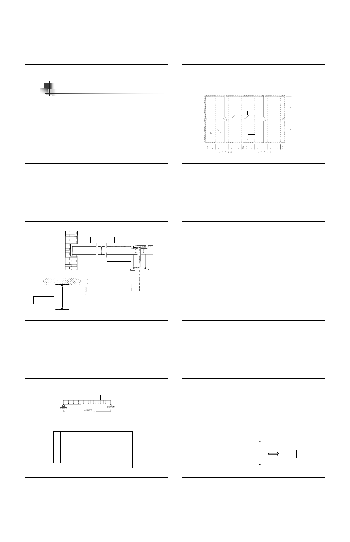
FLOOR BEAM
1.5.
Beam support on wall
Beam can be supported on „concrete cushion”
or additional steel plate.
10
FLOOR BEAM
1.6.
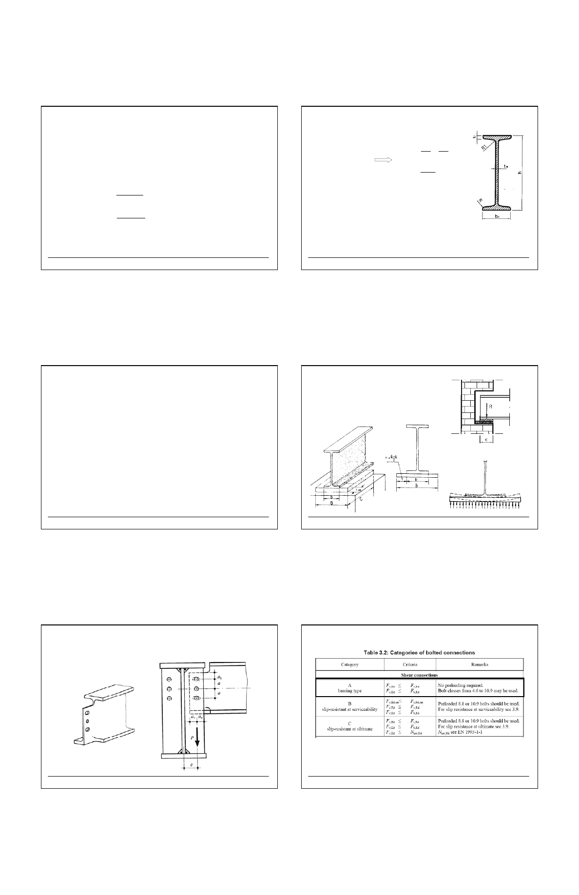
Beam support on plate girder (acc. to PN-EN 1993-1-8)
The nominally pinned, bolted joint is designed. The beam in connected to the plate
girder by transverse stiffener.
11
FLOOR BEAM
12
FLOOR BEAM
Wyszukiwarka
Podobne podstrony:
met5zn regresja student id 2936 Nieznany
Cw1 student id 122803 Nieznany
PROJEKT nr 1 STUDENT id 399181 Nieznany
met1zn student id 293607 Nieznany
Lab 2 pdt i02 ver 01 id 749433 Nieznany
budynek PW 2007 student id 9490 Nieznany
adhd student id 51541 Nieznany
PK zaoczne STUDENCI 1 id 359548 Nieznany
Cw2 student id 123177 Nieznany
Miazdzyca dla Studentow id 2982 Nieznany
Info dla studentow id 213290 Nieznany
Pompa wentylator studenci id 28 Nieznany
Badania nad reklam student id 7 Nieznany (2)
Mpk ver 24 03 2014 id 309156 Nieznany
Bhp kolokwium dla studentow id Nieznany (2)
II CR 178 64 id 209811 Nieznany
więcej podobnych podstron