
233
In This Chapter
11
Using Design Variables
You can assign variables to the parametric dimensions
that control a part. Variables can be assigned to the
active part, or they can be global.
Active part design variables control only the features of
the part they are assigned to. Global design variables
control the features of any number of parts.
Autodesk
®
Mechanical Desktop
®
automatically
reevaluates parts, and updates them when design
variables have been modified.
■
Creating active part design
variables
■
Assigning variables to an active
part
■
Modifying design variables
■
Creating global design variables

234
|
Chapter 11
Using Design Variables
Key Terms
Term
Definition
active part variable
A parametric variable used in the dimensions that control features of the active
part.
global variable
A parametric variable that can be used by any number of parametric features and
parts. Also used for single parts and to constrain parts.
helical sweep
A geometric feature defined by the volume from moving a profile along a 3D
path about a work axis.
pitch
The measured distance parallel to the axis of a helical path, from one point on the
path to the corresponding point on the adjacent revolution.
profile plane
A work plane at the start point of a helical path, placed normal to the start of the
path or at the center of the axis/path.
start angle
The angle at which a helical path begins from the X axis of the active sketch
plane.
table driven variable
A global or active part design variable controlled by values in a linked external
spreadsheet.
taper angle
The angle where a helical sweep is tapered as it is created.
Basic Concepts of Design Variables
|
235
Basic Concepts of Design Variables
Parts and features are controlled by dimensions and other parameters that
define their shapes. By creating design variables and assigning them to these
parameters, you gain greater control over these values. There are two types of
design variables:
■
Global
■
Active part
You use global design variables when you want to control parameters that
belong to more than one part. When you want to control only a specific part,
you use active part design variables.
You can create design variables using the Design Variables dialog box, or you
can use the Equation Assistant dialog box to create design variables on the
fly as you are creating a part.
Design variables are also used in tables to control versions of a part. You learn
to create these tables in chapter 15, “Creating Table Driven Parts.”
This tutorial introduces design variables for controlling features. The tutorial
drawing file contains a helical sweep. For clarity, the sweep is represented by
four wires. The work features used to create the sweep are visible to help you
understand how it was created. Before you begin the tutorial, turn off the vis-
ibility of the work features, and set the number of wires to a lower value; this
increases the speed of recalculation and regeneration of the part.
Open the file helix1.dwg in the desktop\tutorial folder.
NOTE
Back up the tutorial drawing files so you still have the original files if you
make a mistake. See “Backing up Tutorial Drawing Files” on page 40.
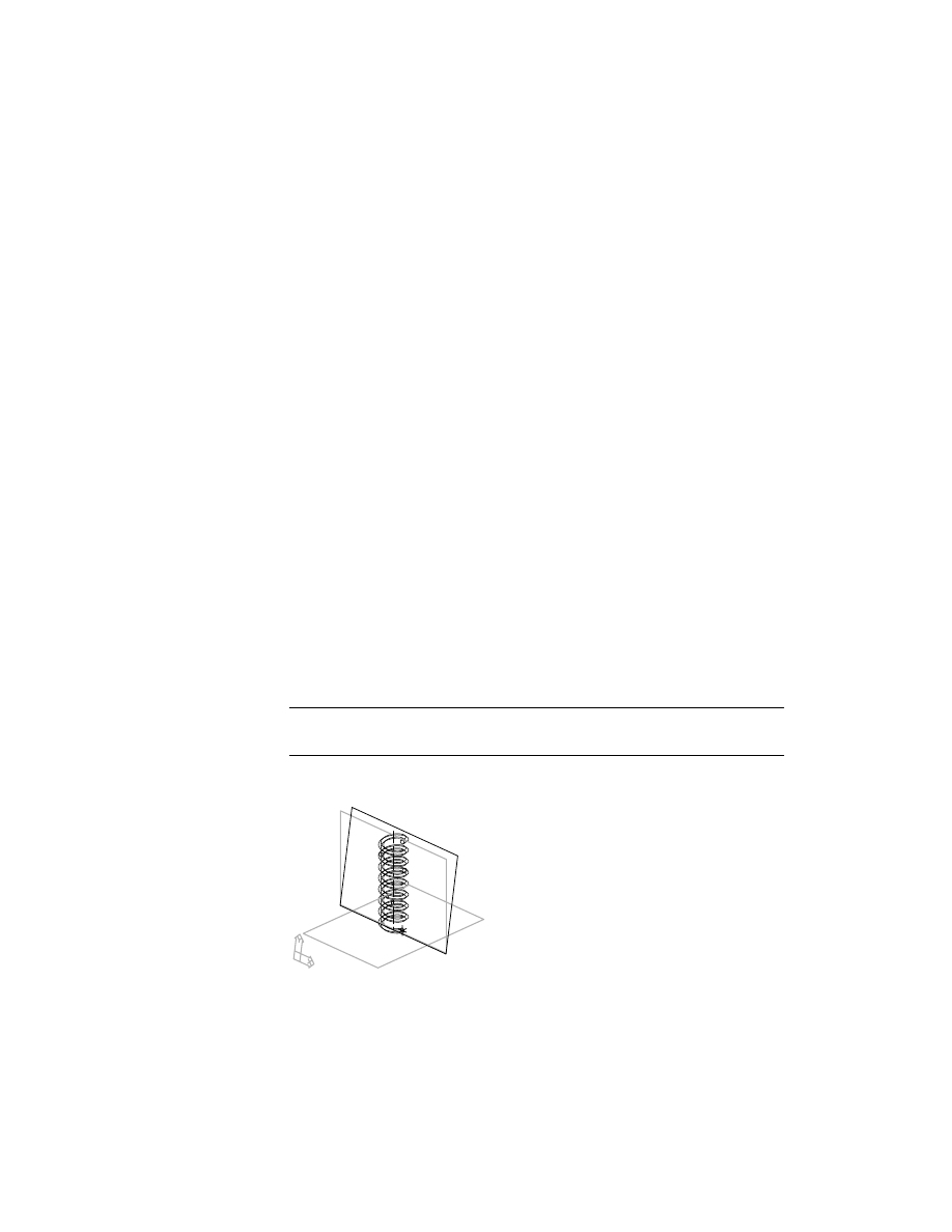
The drawing file contains a spring created from a helical sweep.
236
|
Chapter 11
Using Design Variables
Three work planes are associated with the part. Two were used to create the
sketched work axis for the sweep. The third, also called a profile plane, was
created normal to the start of the path when it was defined. It was used to
sketch the profile for the sweep. The profile is constrained to a work point at
the beginning of the path.
Preparing The Drawing File
Before you begin, turn off the visibility of the work features. Leave the work
axis visible because it will be helpful in keeping you oriented when you
change the variables that control the 3D path.
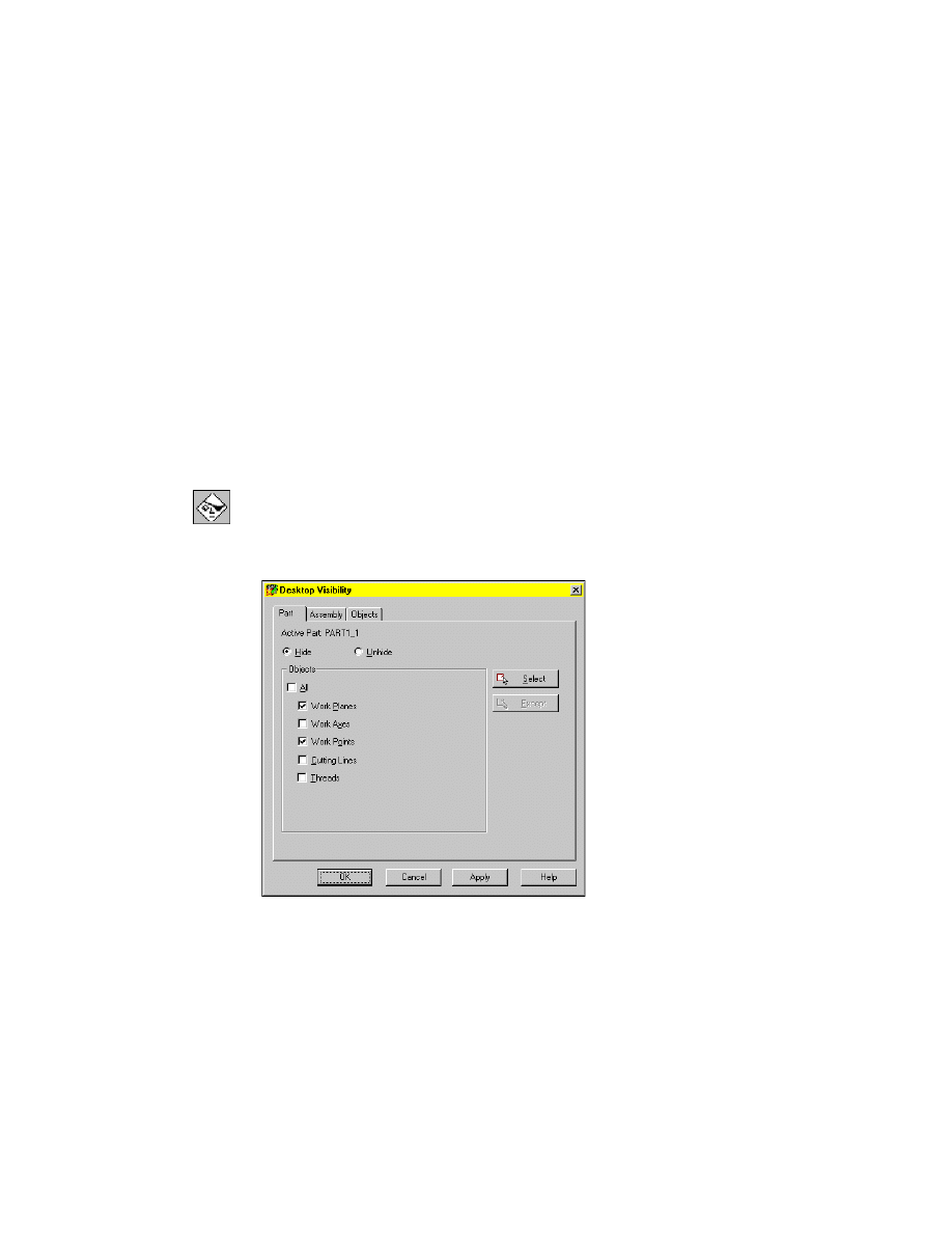
To hide a work feature
1
Use
AMVISIBLE
to turn off the visibility of the first work plane.
Desktop Menu
Part ➤ Part Visibility
2
In the Desktop Visibility dialog box, with Hide turned on, choose Work
Planes and Work Points.
Choose Apply.
Choose OK to exit the dialog box.
Preparing The Drawing File
|
237
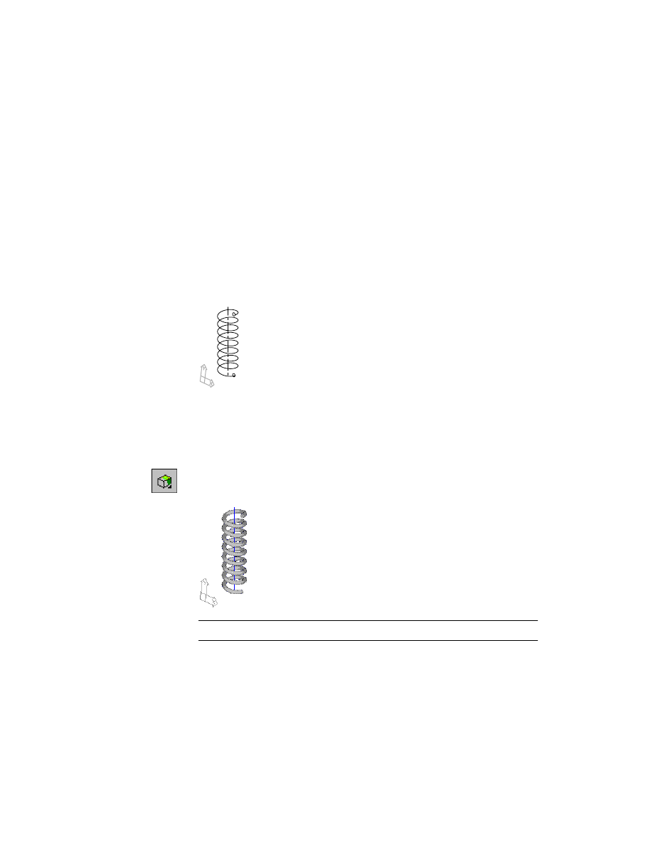
To speed up recalculations and regenerations of the helical sweep, set the
ISOLINES
variable to its default value. This will display the sweep using only
one wire. Currently it is set to display the sweep as a helical tube.
To set isolines
1
Change the setting for
ISOLINES
, responding to the prompt.
Command
ISOLINES
New value for ISOLINES <8>:
Enter 4
2
Use
REGEN
to regenerate your drawing.
Desktop Menu
View ➤ Regen
The helix should look like this.
To see your model better, use the shade button on the Desktop View toolbar
to toggle shading on and off. If you prefer, leave the shade option on.
To toggle shading of a part
1
Use
SHADE
to shade your part.
Desktop Menu
View ➤ Shade ➤ Gouraud Shaded
Your part should now look like this.
NOTE
Shading is turned off throughout this tutorial.
The Desktop View toolbar also contains commands to dynamically rotate
your design and control views.
238
|
Chapter 11
Using Design Variables
To dynamically rotate a part
1
Use
3DORBIT
to rotate the view of your part.
Context Menu
In the graphics area, right-click and choose 3D Orbit.
2
Select a point near the center of the part. This point acts as the central point
for the rotation. Press the mouse button as you move your cursor around the
screen. The part dynamically rotates as the cursor moves.
3
Release the mouse button when the display is to your liking.
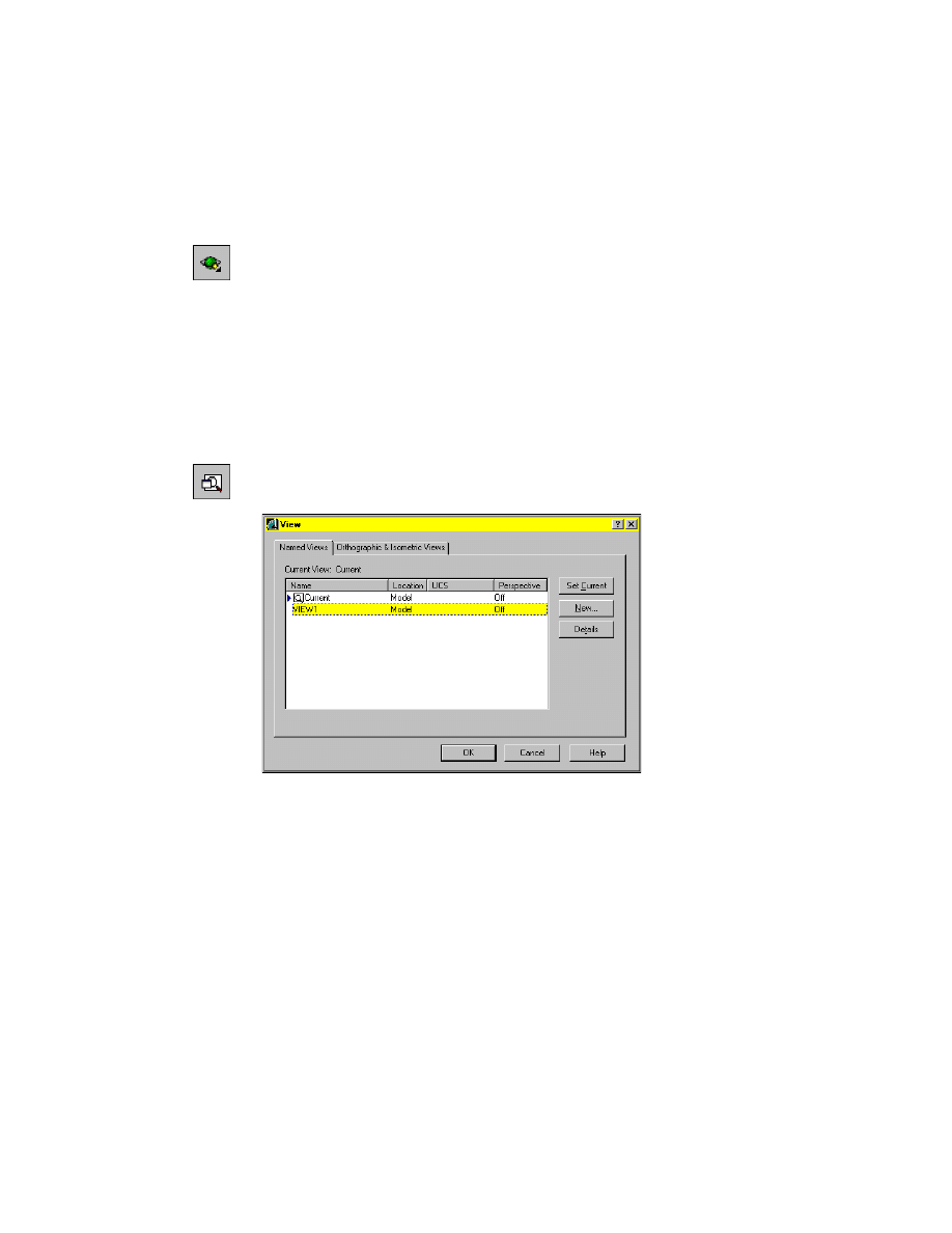
In the next procedure, you restore the view to its original display. The
helix1.dwg file has one saved view, View1.
To restore a saved view
1
Use
VIEW
to restore the original drawing view.
Desktop Menu
View ➤ Named Views
2
In the View dialog box, highlight View1, and choose Set Current.
Choose OK.
Your drawing is returned to the original view.
Next, you define active part design variables and then assign them to the
existing helical part.

Using Design Variables
|
239
Using Design Variables
Design variables provide a tool for controlling dimensions, and using equations
and relationships between dimensions. Changing one or more variables affects
the entire part.
Design variables can be either active or global.
Active Part Design Variables
Active part design variables control only the part they are assigned to.
Global Design Variables
Global design variables allow you to use the same variables for multiple fea-
tures across multiple parts. If you are designing multiple parts in the same
file, you may use global design variables to control some or all of the parts
with the same variables.
Creating Active Part Design Variables
The helical sweep is governed by the following parameters:
■
Type of sweep
■
Number of revolutions
■
Pitch
■
Height
■
Shape
■
Diameter of the sweep
■
Taper angle
■
Orientation
■
Start angle
■
Radius of the swept profile
240
|
Chapter 11
Using Design Variables
In addition to the method used in the following exercises, you can create
design variables in the Equation Assistant dialog box while you are in the
modeling process. In the Equation Assistant dialog box, you right-click in the
variables list area and choose New. A space for the new variable is provided
at the end of the list, and your cursor is positioned in the Name column.
There you enter a name for the new variable, and then you define it in the
Equation column.
In this lesson, you create variables and parametric equations to control the
number of revolutions, height, and diameter of the sweep. You also assign a
variable to control the radius of the profile that is swept along the helical
path. Because you are working with a single part, you create these variables
as active part design variables.
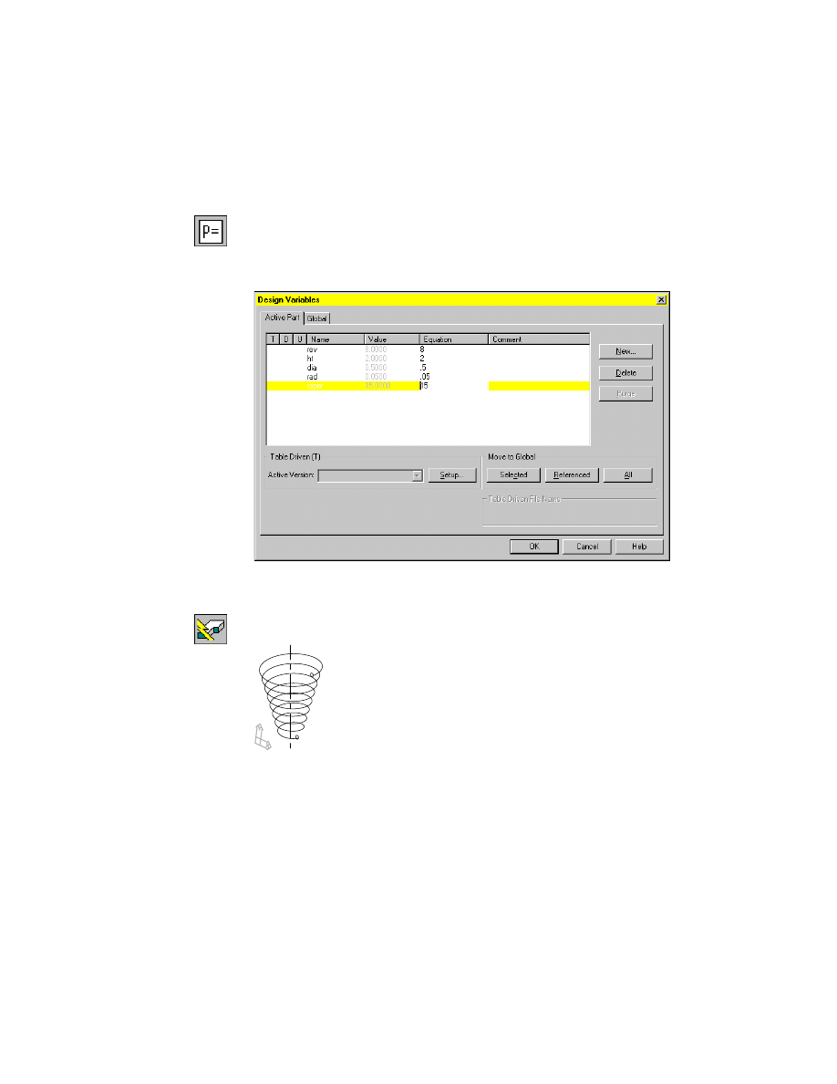
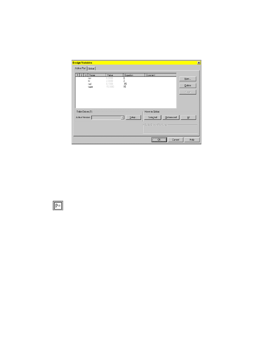
To create an active part design variable
1
Use
AMVARS
to create a design variable.
Desktop Menu
Part ➤ Design Variables
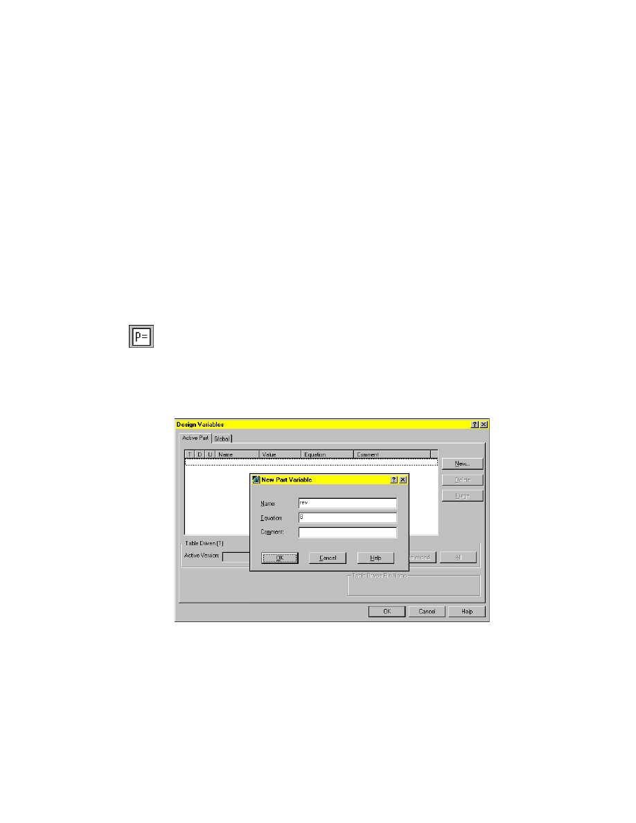
2
In the Design Variables dialog box, make sure the Active Part tab is selected
and choose New.
3
In the New Part Variable dialog box, specify:
Name:
Enter rev
Equation:
Enter 8
Press
ENTER
.
Creating Active Part Design Variables
|
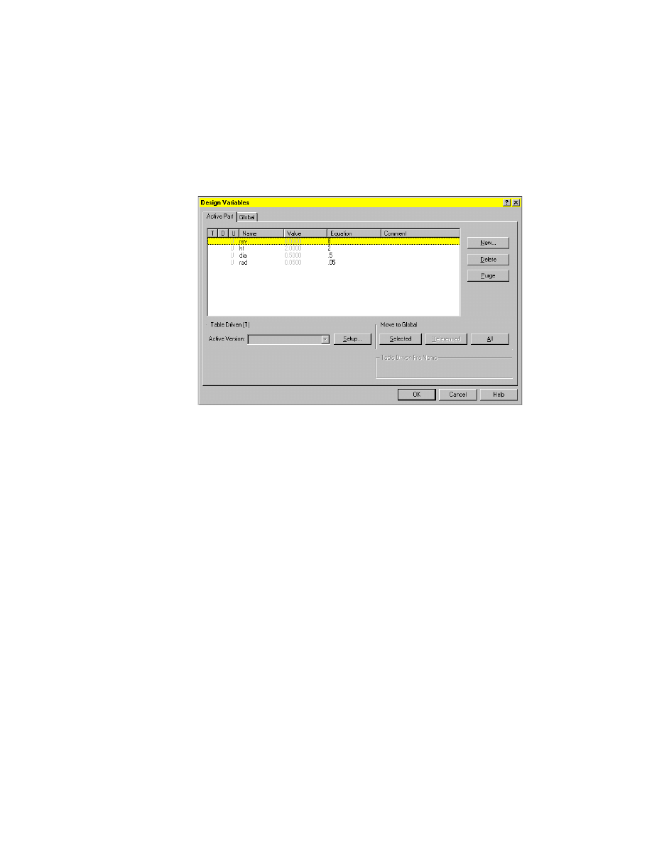
241
4
Repeat step 3 to enter the following variables:
Ht
2
Dia
.5
Rad
.05
Choose OK.
The next step is to edit the existing part by replacing its dimensions with the
design variables you have just created.
242
|
Chapter 11
Using Design Variables
Assigning Design Variables to Active Parts
Before the spring can be table driven, you need to assign the design variables
you have defined. You edit the sweep feature and the profile used to create
the sweep. You change the values controlling the feature with the design
variables you have just created.
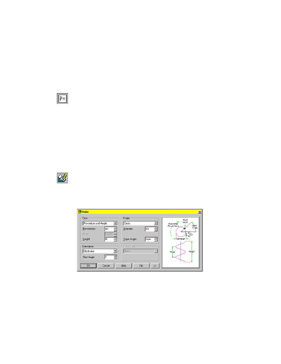
To edit a sweep feature
1
Use
AMDIMDSP
to set dimensions to display as equations.
Context Menu
In the graphics area, right-click and choose Dimensioning
➤ Dimensions as Equations.
2
Use
AMEDITFEAT
to define the sweep feature to edit.
Context Menu
In the graphics area, right-click and choose Edit Features
➤ Edit.
Highlight the helical sweep.
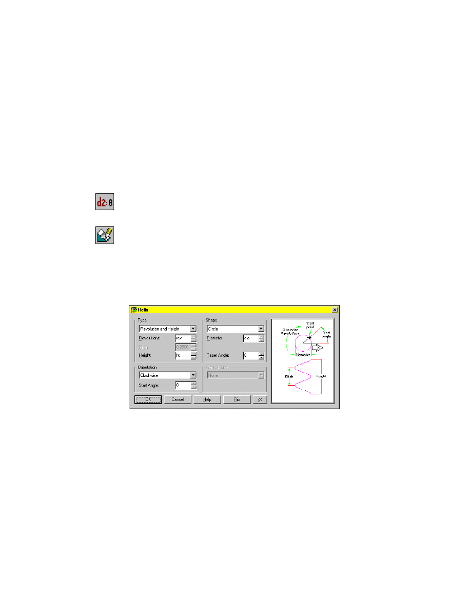
3
In the Helix dialog box, enter the following:
Revolutions:
rev
Height:
ht
Diameter:
dia
Choose OK. Then choose OK to exit the Sweep dialog box.
You have assigned design variables to the parameters controlling the sweep.
Assigning Design Variables to Active Parts
|
243
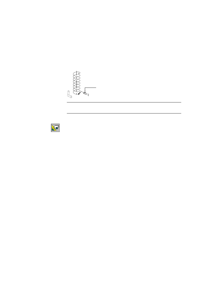
4
Assign the last variable to the radius of the profile, responding to the prompts
as follows:
Select object:
Select the dimension (1)
Enter dimension value <.1>:
Enter rad
Select object:
Press
ENTER
NOTE
For clarity, shading has been turned off in these illustrations. You may
prefer to keep it on throughout the tutorial.
5
Use
AMUPDATE
to update the part, responding to the prompt.
Context Menu
In the graphics area, right-click and choose Update Part.
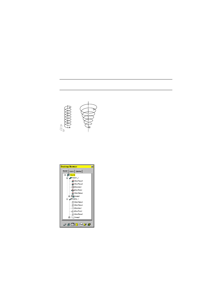
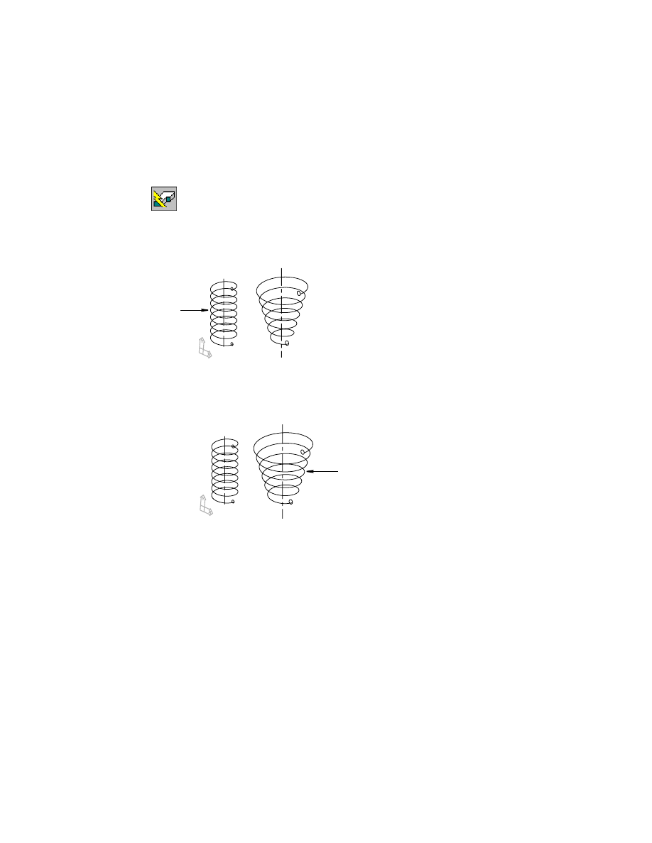
The spring is updated. The part changes because the value for the rad design
variable you assigned is not the same as the original value used to create the
sweep.
1
244
|
Chapter 11
Using Design Variables
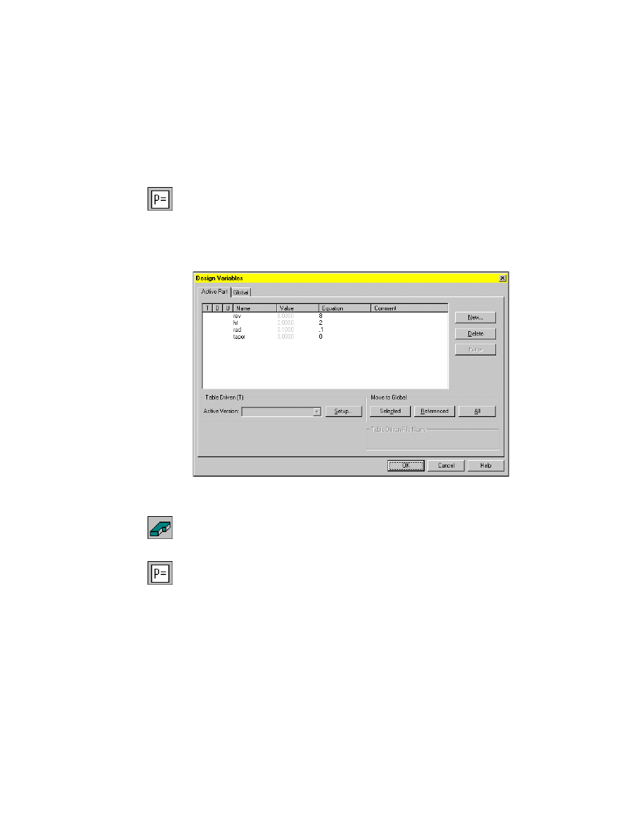
Modifying Design Variables
Design variables can be added and modified anytime during the design process.
When the part is updated, changes to the design variables are automatically
applied.
In this exercise, you add a design variable for a taper angle on the active part.
To add a design variable to an active part
1
Use
AMVARS
to add a design variable.
Desktop Menu
Part ➤ Design Variables
2
In the Design Variables dialog box, with the Active Part tab selected, choose New.
3
In the New Part Variable dialog box, specify:
Name:
taper
Equation:
Enter 0
Choose OK.
4
Choose OK to exit the Design Variables dialog box.
Next, you edit the sweep feature by adding the new variable to its design
parameters.
To edit a sweep
feature
1
Use
AMEDITFEAT
to add the new design variable to the sweep feature.
Context Menu
In the graphics area, right-click and choose Edit Features
➤ Edit.
2
Highlight the helical sweep.
3
In the Helix dialog box, specify the following:
Taper Angle:
taper
Choose OK. Then choose OK to exit the Sweep dialog box.
4
Press
ENTER
to end the command.
Modifying Design Variables
|
245
To modify a design variable
1
Use
AMVARS
to modify the design variable.
Desktop Menu
Part ➤ Design Variables
2
In the Design Variables dialog box, with the Active Part tab selected, high-
light the taper variable. In the highlighted line, double-click the Equation
field and enter 15.
Choose OK to exit the Design Variables dialog box.
3
Use
AMUPDATE
to update the part.
Context Menu
In the graphics area, right-click and choose Update Part.
Save your file.
246
|
Chapter 11
Using Design Variables
Working with Global Design Variables
You can assign global variables to more than one part to control similar fea-
tures. In this lesson, you move some of the active part design variables to glo-
bal variables and assign them to two parts.
Open the file helix2.dwg in the desktop\tutorial folder.
NOTE
Back up the tutorial drawing files so you still have the original files if you
make a mistake. See “Backing up Tutorial Drawing Files” on page 40.
The drawing contains two springs created from helical sweeps.
Both helical sweeps have active part design variables already assigned to
them. In this lesson, you create global design variables to control identical
features of each helix.
First, expand the Browser hierarchy by clicking the plus sign in front of
HELIX2. Then click the plus sign in front of PART1_1 and PART2_1. The
Browser should look like this. Notice PART1_1 is the active part.
Working with Global Design Variables
|
247
Next, examine the active part design variables for both parts.
To examine a design variable for an active part
1
Use
AMVARS
to open the Design Variables dialog box.
Desktop Menu
Part ➤ Design Variables
2
In the Design Variables dialog box, with the Active Part tab selected, examine
the values for the design variables assigned to PART1_1.
You should see four variables controlling the number of revolutions, height,
radius of the swept profile, and the taper angle of the active part. There is no
variable defined for the diameter of the helical sweep.
Choose OK to exit the dialog box.
3
Use
AMACTIVATE
to activate PART2_1.
Browser
In the Browser, right-click PART2_1 and choose Activate
Part.
4
Examine the design variables assigned to PART2_1.
Desktop Menu
Part ➤ Design Variables
248
|
Chapter 11
Using Design Variables
5
In the Design Variables dialog box, make sure the Active Part tab is selected.
Choose OK.
Both parts have active part design variables controlling the same features.
The variable controlling the height of both helical sweeps contains the same
value.
Next, you move this active part design variable to a global design variable so
that one variable controls both parts.
To move an active part variable to a global design variable
1
Open the Design Variables dialog box.
Desktop Menu
Part ➤ Design Variables
2
In the Design Variables dialog box, with the Active Part tab selected, high-
light the ht variable. Under Move to Global, choose Selected.
The variable is removed from the list of active part design variables.
3
Click the Global tab and examine the list of global variables.
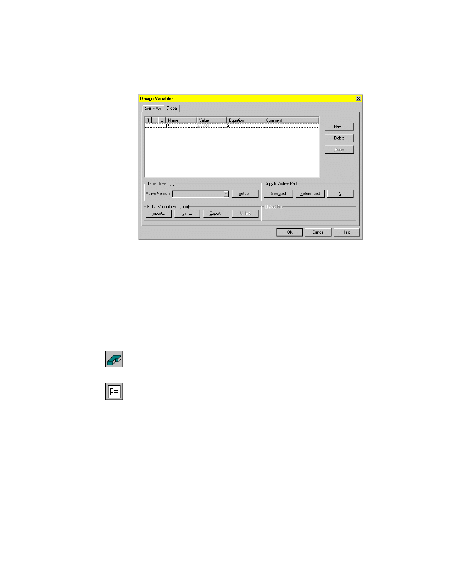
Working with Global Design Variables
|
249
Choose OK to exit the dialog box.
Mechanical Desktop re-evaluates the features of the part and updates the
part. Because the value of the variable has not changed, the part does not
change.
Although the ht variable for PART2_1 has been moved to global, the same
variable for PART1_1 is still an active part design variable. Because one global
variable will drive both parts, you remove the ht variable from the PART1_1
list of active part design variables.
To delete an active part design variable
1
Use
AMACTIVATE
to activate PART1_1.
Browser
In the Browser, right-click PART1_1 and choose Activate
Part.
2
Open the Design Variables dialog box.
Desktop Menu
Part ➤ Design Variables
3
In the Design Variables dialog box, with the Active Part tab selected, high-
light the ht variable and choose Delete.
The variable is removed from the list of active part design variables.
Choose OK to exit the dialog box.
PART1_1 is re-evaluated and updated. The global design variable is now con-
trolling the height of both helical sweeps.
250
|
Chapter 11
Using Design Variables
Next, you create a new global design variable to control the diameter of the
springs and assign it to both parts. Then you modify the value of the global
design variable controlling their height.
To create a global design variable
1
Open the Design Variables dialog box.
Desktop Menu
Part ➤ Design Variables
2
In the Design Variables dialog box, select the Global tab and choose New.
3
In the New Part Variable dialog box, specify:
Name:
Enter dia
Equation:
Enter .75
Choose OK. The Global tab now contains two variables, ht and dia.
Choose OK to exit the dialog box.
The parts do not change because the variable has not yet been assigned to
them.
To assign a global design variable to a part
1
Edit the sweep feature for PART1_1:
Context Menu
In the graphics area, right-click and choose Edit Features
➤ Edit.
2
Highlight the helical sweep.
3
In the Helix dialog box, specify the following:
Diameter:
dia
Choose OK. Then choose OK to exit the Sweep dialog box.
Working with Global Design Variables
|
251
4
Continue on the command line.
Select object:
Press
ENTER
5
Update the part.
Context Menu
In the graphics area, right-click and choose Update Part.
Enter an option [active Part/Assembly/aLl parts/linKs] <active Part>:
Press
ENTER
Mechanical Desktop updates PART1_1 using the new global design variable
to control the diameter of the sweep.
6
Activate PART2_1.
7
Repeat steps 1 through 5 for PART2_1.
Your drawing should look like this.
Next, you modify the global design variable controlling the height of the
parts.
PART1_1
PART2_1
252
|
Chapter 11
Using Design Variables
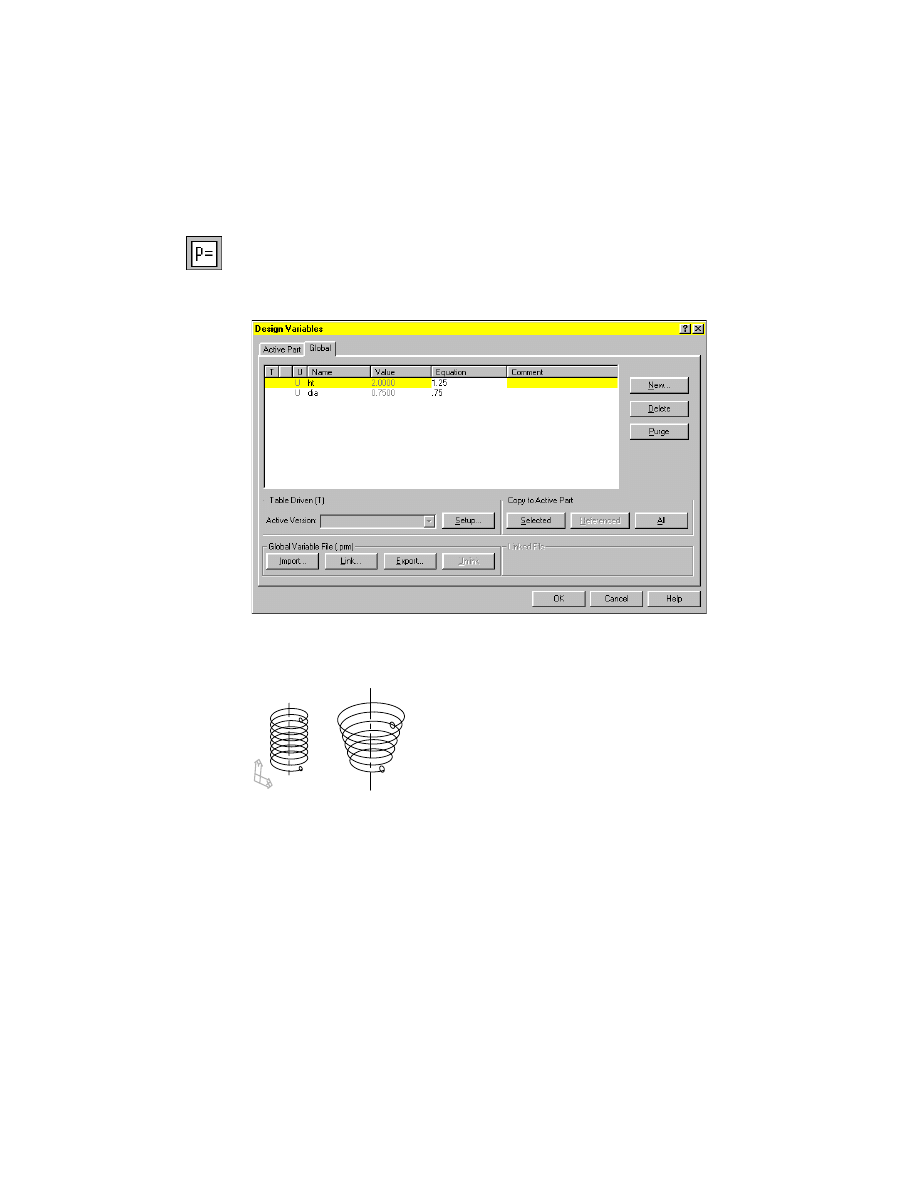
To modify a global design variable
1
Open the Design Variables dialog box.
Desktop Menu
Part ➤ Design Variables
2
In the Design Variables dialog box, with the Global tab selected, highlight
the ht variable. In the highlighted line, double-click the Equation field and
enter 1.25.
Choose OK to exit the dialog box.
Mechanical Desktop re-evaluates the features and updates both parts.
Design variables are a powerful way to control the features of a part. Both
active part and global design variables may be table driven. To create a table
driven part, you use Microsoft
®
Excel software to create a spreadsheet con-
taining values for different versions of a part. You learn more about table
driven parts in chapter 15, “Creating Table Driven Parts.”
Wyszukiwarka
Podobne podstrony:
Ch11 Q1
History Costume History Costume Design Viking Women
[2001] State of the Art of Variable Speed Wind turbines
Eurocode 5 EN 1995 1 1 Design Of Timber Structures Part 1 1 General Rules
ch11 12 wiele zm
[Instrukcja] GDOT Design Policy Manual Chapter 8 Roundabouts (USA)
100108 nmea 0183 sentences not recommended for new designs
journal design
A New Hybrid Transmission designed for FWD Sports Utility Vehicles
CH11 2
Programming Designs
DesignSem1
Language Curriculum Design
[5] Root Locus Design
How Do You Design
Kartridże atramentowe Hewlett Packard DesignJet 500
PCB Design Tutorial
więcej podobnych podstron