
GDOT Design Policy Manual Revised 03/11/2011
Chapter 8 Contents
i
Chapter 8 Contents
8.
8.2. Roundabout Validation Process
Roundabout Feasibility Studies
Peer Review of Feasibility Studies
Peer Review of Construction Plans
Pedestrian Design Considerations
Treatments for High Speed Approaches
8.3.11. Staging of Improvements

GDOT Design Policy Manual Revised 03/11/2011
Chapter 8 Contents
ii
List of Tables
Table 8.1. Planning-level Estimates of Lane Requirements. 5
List of Figures
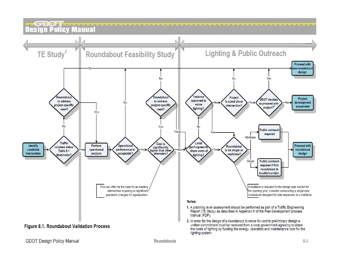
Figure 8.1. Roundabout Validation Process
3
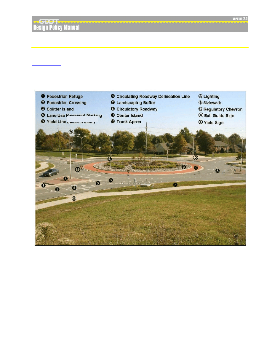
Figure 8.2. Key Roundabout Physical Features
15
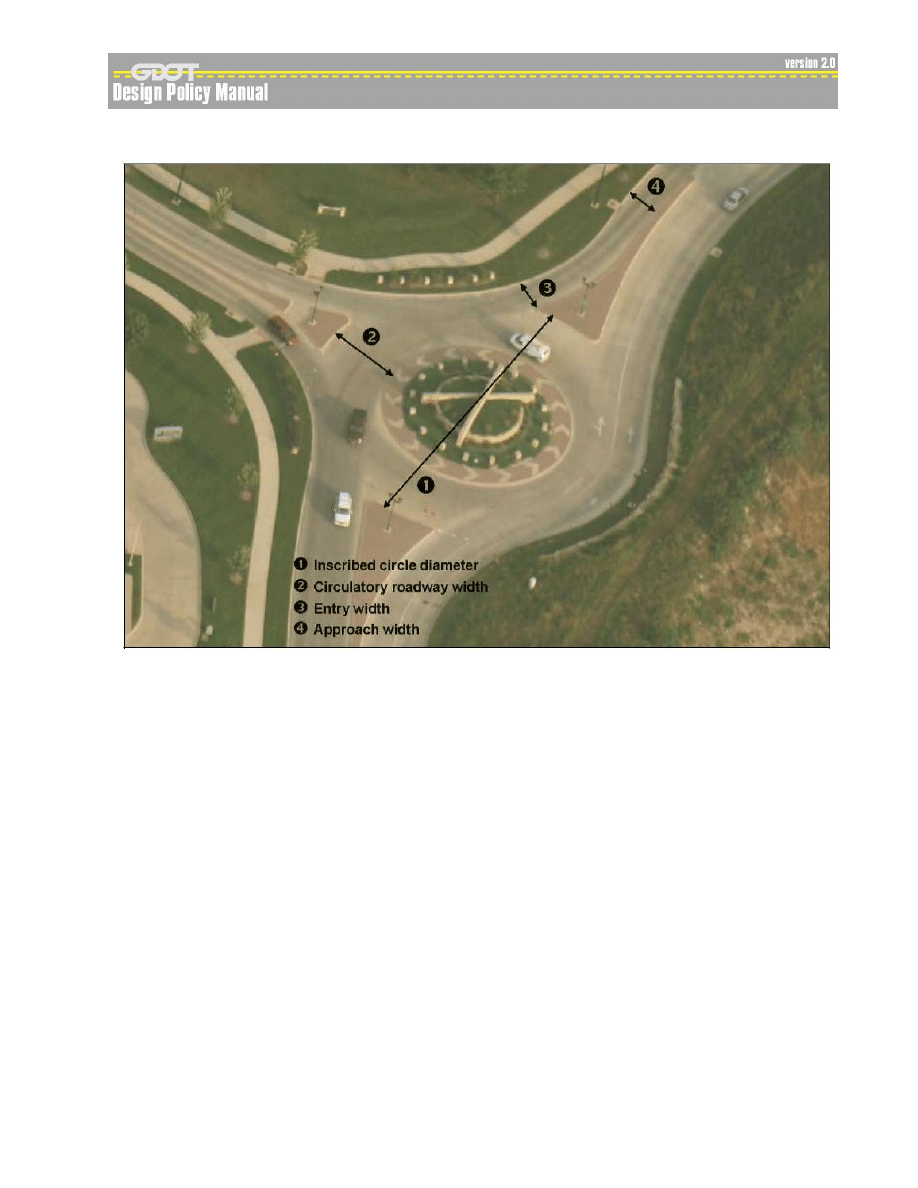
Figure 8.3. Key Roundabout Design Elements
17

GDOT Design Policy Manual Revised 03/11/2011
Roundabouts
8-1
8
8
.
.
R
R
O
O
U
U
N
N
D
D
A
A
B
B
O
O
U
U
T
T
S
S
8
8
.
.
1
1
.
.
I
I
n
n
t
t
r
r
o
o
d
d
u
u
c
c
t
t
i
i
o
o
n
n
A modern roundabout is a type of circular intersection characterized by channelized approaches, a
generally circular shape, yield control at entry, and geometric features that create a low-speed
environment. They have been demonstrated to provide a number of safety, operational, and other
benefits when compared to other types of intersections. Specifically, they have fewer conflict
points, lower speeds, provide for easier decision making and have been found to reduce crashes
(especially those including fatalities and injuries), traffic delays, fuel consumption, and air pollution.
Roundabouts can be categorized into three basic types: mini-roundabouts, single-lane
roundabouts, and multilane roundabouts. A detailed introduction to each is provided in Chapter 1
of the National Cooperative Highway Research Program (NCHRP)
. This chapter of the GDOT Design Policy Manual specifically addresses single-
lane and multilane roundabouts; for the design of mini-roundabout refer to
Guidance Memorandum on Consideration and Implementation of Proven
, which identifies roundabouts as one of nine safety countermeasures
recognized and supported by FHWA. This document states the following:
Roundabouts are the preferred safety alternative for a wide range of intersections.
Although they may not be appropriate in all circumstances, they should be considered as
an alternative for all proposed new intersections on federally-funded highway projects,
particularly those with major road volumes less than 90 percent of the total entering
volume. Roundabouts should also be considered for all existing intersections that have
been identified as needing major safety or operational improvements. This would include
freeway interchange ramp terminals and rural intersections.
GDOT also considers roundabouts as the preferred safety and operational alternative for a wide
range of intersections on public roads. Specifically, a roundabout shall be considered as an
alternative in the following situations:
for any intersection being designed on new location or to be reconstructed;
for all existing intersections that have been identified as needing major safety or operational
improvements; and
for all intersections where a request for a traffic signal has been made.
A traffic engineering study (TE study) is prepared for all intersections where a signal permit is
requested, as required by the
GDOT Plan Development Process (PDP)
. This study includes a
planning level assessment as to whether or not a roundabout is expected to perform acceptably. If
a roundabout is expected to perform acceptably, a roundabout feasibility study (feasibility study)
should be prepared.
Each proposal for a roundabout should be developed and evaluated based on the guidelines
contained within
and the guidelines presented in the following sections of this chapter.
Additional guidance documents are listed in Section 8.4.1.

GDOT Design Policy Manual Revised 03/11/2011
Roundabouts
8-2
8
8
.
.
2
2
.
.
R
R
o
o
u
u
n
n
d
d
a
a
b
b
o
o
u
u
t
t
V
V
a
a
l
l
i
i
d
d
a
a
t
t
i
i
o
o
n
n
P
P
r
r
o
o
c
c
e
e
s
s
s
s
When considering a roundabout, a variety of alternatives should be evaluated to determine whether
or not a roundabout is the most appropriate alternative. These alternatives should include all
conventional intersection forms appropriate for the intersection being considered and will often
include two-way stop control, all-way stop control, and/or signal control. Chapter 3 of
provides guidance for comparing the performance of a roundabout to these three forms of
intersection control. A signalized intersection is only considered if signal warrants are met, as
determined by a TE study.
Figure 8.1 presents a validation process which should be used to validate the decision to use a
roundabout for a given intersection. This validation process includes: (1) an initial planning level
assessment performed as part of a TE study; (2) a roundabout feasibility study; (3) obtaining
agreement from local government to participate in lighting costs; and (4) a program of public
outreach. The final result of this validation process is a decision to proceed with either a
roundabout or conventional (i.e., or nonroundabout) intersection design, or to suspend project
development.
For stand-alone intersection projects, the roundabout validation process should be completed prior
to submission of the concept report for review and approval. Where the intersection is part of a
larger project this process should be completed prior to requesting the preliminary field plan review.
8.2.1. Planning Level Assessments
The roundabout validation process begins with a planning level evaluation to assess the general
suitability of constructing a roundabout at the intersection. This evaluation is performed as part of a
TE study, but may be included in the feasibility study. Exhibit 3-1 of NCHRP 672 provides an
excellent overview of key planning principles.
Listed below are conditions where roundabouts are commonly found to be advantageous over other
forms of intersection control. An overview of the primary advantages and disadvantages of
roundabouts is presented in Exhibit 2-5 of
Safety
Intersections with historically high crash rates.
Roads with a historical problem of excessive speeds.
Intersections with more than four legs or with difficult skew angles.
Operation
Intersections with a high percentage of turning movements and intersections that must
accommodate U-turns.
Intersections with high traffic volumes at peak hours but relatively low traffic volumes during
non-peak hours.
Intersections where widening one or more approach may be difficult or cost-prohibitive. While
roundabouts may have a larger footprint on the corners of the intersection, the overall space
requirement for a roundabout is often less than for a conventional intersection. This is due to
the shorter queues generated by a roundabout, thereby requiring less queue storage space on
approach legs.
Ramp terminal intersections within freeway service interchanges. Roundabouts often make
more efficient use of an existing bridge by reducing the queues at each ramp terminal
intersection.

GDOT Design Policy Manual Revised 03/11/2011
Roundabouts
8-4
Intersections where traffic growth is expected to be high and future traffic patterns are uncertain.
A single-lane roundabout can be constructed with allowance for future expansion to a multilane
roundabout, and be expanded if and when significant increases in traffic volumes occur.
Locations where the speed environment or the number of through lanes of the road changes, for
instance, at the fringe of an urban environment.
Intersections where signalization cannot provide an adequate level of service.
Traffic Control
Existing two-way stop-controlled intersections with high side-street delays, particularly those
that do not meet signal warrants.
Intersections or corridors where traffic calming is a desired outcome of the project.
Aesthetics
Intersections at a gateway or entry point to a campus, neighborhood, commercial development,
or urban area. These may be locations with a need to provide a transition between land-use
environments such as between residential and commercial areas.
Intersections where community enhancement may be desirable.
The presence of any of the following conditions will normally be unfavorable for a roundabout.
These conditions do not preclude a roundabout from further consideration, but should be carefully
considered when choosing and designing a roundabout.
Intersections in close proximity to a signalized intersection where queues may spill back into the
roundabout (e.g., coordinated arterial signal systems).
Locations with steep grades and unfavorable topography that may limit visibility of the
roundabout.
Intersections in close proximity to an at-grade railroad crossing.
Intersections where an unacceptable delay to the major road could be created. Roundabouts
introduce some geometric delay to all through and left turning traffic entering the intersection,
including the major street.
Heavy pedestrian or bicycle movements in conflict with high traffic volumes that consequently
may require pedestrian signals.
Table 8.1 can be used to estimate the number of circulatory lanes required for a single- or two-lane
roundabout. One and two-lane roundabouts should operate acceptably below these thresholds and
are based on Exhibit 3-12 of
. In addition, the opening and design year volumes for
traffic entering the roundabout from the major road should normally be less than 90% of the total
volume entering the roundabout.
Where turning movement data is available, an estimate of the required number of entry lanes at
each leg can be obtained using Exhibit 3-14 of
. Sample calculations are provided in
Exhibits 3-15 and 4-3.

GDOT Design Policy Manual Revised 03/11/2011
Roundabouts
8-5
Table 8.1. Planning-level Estimates of Lane Requirements.
No. of Circulatory Lanes
ADT
1
(design year)
% Traffic on Major Road
2
(opening & design year)
Single-lane
< 25,000
< 90
Two-lane
< 45,000
< 90
1
Based on traffic entering the circulatory roadway, for a four-leg roundabout. A
reasonable approximation for a three leg roundabout is 75% of the values shown.
2
The volume of traffic entering the roundabout from the major road divided by the total
traffic volume entering the roundabout, as a percentage.
If traffic volumes are above the thresholds shown in Table 2.1, or if site conditions are unfavorable
to a roundabout, an acceptable conventional intersection type may be selected without further
evaluation. Nevertheless, a roundabout may still operate better than a conventional intersection
and may be carried forward for more detailed consideration as part of a feasibility study.
8.2.2. Roundabout Feasibility Studies
A feasibility study should be prepared for all roundabouts. The objective of the feasibility study is to
document the decision-making process which demonstrates that a roundabout is (or is not) the
most appropriate intersection control form for a specific intersection. The feasibility study also
includes a geometric layout of the selected roundabout alternate which can be carried forward to
preliminary design. For a stand-alone intersection project, the project concept report may be
formatted to incorporate the feasibility study.
A well-prepared feasibility study is important for identifying and supporting the selection of a
roundabout. Nevertheless, the scope of a feasibility study will vary depending on project conditions
and the type and complexity of the proposed roundabout. For example, an intersection of two state
routes having a history of injury crashes may not require a detailed cost comparison, considering
the significant reduction in injuries that can be expected with a roundabout. On the other hand, the
use of a roundabout within a highly urbanized corridor having closely spaced, coordinated signals
may require a very detailed feasibility study that goes beyond the scope of what is outlined below.
A typical feasibility study can be organized as follows:
Section 1, Project Background & Site Conditions: include a summary of the project need, a
description of the corridor, and a sketch of existing conditions in the vicinity of the intersection.
The sketch should show land-use, access, existing right-of-way, and any physical constraints
that may affect the location and design of a roundabout.
Section 2, Safety Assessment: include a tabulated analysis of crash data for the three most
recent years (at minimum) for which data is available and a comparison to statewide averages.
If the purpose of considering a roundabout is to improve the safety at an existing intersection, it
is recommended that a crash diagram be prepared. The crash diagram should show the types
of crashes and the direction each car was travelling.
A roundabout is particularly favorable for addressing crashes involving crossing and turning
traffic. Further information regarding safety and roundabouts is presented in Chapter 5 of
Section 3, Alternate Sketches: include sketches of all design alternates being considered.
These can be effectively presented on an aerial photo base map of the intersection and vicinity.

GDOT Design Policy Manual Revised 03/11/2011
Roundabouts
8-6
Section 4, Operational Analyses: include operational analyses using peak hour traffic
volumes for each design alternate and for opening and design years. The results of each
analysis should be presented by lane group in terms of volume-to-capacity ratio, average
control delay, level of service, and 95th percentile queue. Based on the results of these
analyses the performance of each alternate should be evaluated, and intersection types
providing adequate performance identified. Further guidance on evaluating the operational
performance of roundabouts can be found in Chapter 4 of
Analyses should be performed using more than one analysis methodology, to identify a range of
expected performance. For example, analyses can be performed using the
to implement the NCHRP Report 572 method and a second method, either the
“SIDRA Standard” method using the software package SIDRA Intersection or the empirical
method using the software package ARCADY.
SIDRA Intersection does not provide a precise implementation of the NCHRP 572 method and
should not be used for that purpose. Simulation software packages should be considered
where modeling of a network of closely spaced intersection is necessary.
Section 5, Cost Comparison: where multiple alternates are expected to provide adequate
operational performance, a cost comparison should be prepared. This analysis may be either
qualitative or quantitative, but should consider significant benefits relating to safety, operational,
and environmental factors and significant costs relating to construction, required right-of-way,
operations, and maintenance. Further guidance on estimating benefits and costs can be found
in Section 3.7 of
. A detailed benefit-to-cost analysis can be helpful for
communicating the benefits of a roundabout to local governments and the public.
Section 6, Alternate Selection: include a brief summary of the findings of the above studies
(usually in a bulleted form) followed by a recommendation of the most favorable alternate. All
assumptions and constraints important to this decision should be included.
Section 7, Conceptual Roundabout Design: include a concept level geometric layout of the
roundabout and approaches. This layout should include the size and location of the roundabout
and the alignment and arrangement of approaches. Major geometric components should be
shown including splitter islands, circulatory roadway, truck aprons, center island, and bypass
lanes (if required).
Geometric and performance checks should include, at minimum - fastest path, design vehicle
swept paths, and stopping sight distance for approaches. Other performance checks can be
completed during preliminary design (See Section 6.7 of
A list of the criteria used to develop the selected layout and key dimensions should be provided.
It is noted that the selection of the most favorable roundabout configuration and layout may
require the development and comparison of multiple roundabout layouts.
If a single-lane roundabout is found to be adequate for ten years after the opening year,
consideration should be given to constructing a single-lane roundabout. This single-lane
roundabout should be designed to be easily retrofitted to a multilane roundabout when traffic
volumes grow to warrant the increased capacity. To allow for this future expansion, the ultimate
configuration of the multilane roundabout should be defined and the footprint of the constructed
roundabout designed to match the footprint of the future multilane roundabout (See Section 6.12
of
).
Section 8, Recommendations: briefly state the reasons for selecting the recommended
alternate. Any specific requirements or constraints to be considered during preliminary design
should be listed and the expected approach for staging briefly described.

GDOT Design Policy Manual Revised 03/11/2011
Roundabouts
8-7
8.2.3. Peer Review of Feasibility Studies
Feasibility studies prepared by GDOT must be reviewed in accordance with the
. After completing this review and making appropriate corrections, a peer review is
performed. A peer review should also be performed for all consultant prepared feasibility studies,
including those prepared for locally administered projects (LAP).
Peer reviews are performed by a Consultant peer reviewer having extensive experience with the
planning, analysis, and design of single-lane, and multilane roundabouts. Consultant peer
reviewers must be pre-approved by the Office of Design Policy and Support.
Informal reviews by a GDOT roundabout SME can be requested at any time during the plan
development process, by sending an e-mail to
roundabout SME directly. Initial reviews are encouraged to occur very early in concept
development.
8.2.4. Lighting
The lighting of a roundabout has been identified by the Department as having substantial
importance to the operational performance and safety of this type of intersection such that
special attention should be given to the design and lighting for a roundabout. Therefore,
GDOT adopts the recommended illumination levels in Table 1 of the Illuminating Engineering
Society
DG-19-08, Design Guide for Roundabout Lighting
(IES DG-19-08) as a standard for
the design of lighting systems for roundabouts. If it is not practical to provide the
illumination levels defined by this table, then the decision to select a value or retain an
existing condition that does not meet this criteria shall require a comprehensive study by
the engineer and the prior approval of a Design Variance from the GDOT Chief Engineer.
Both
emphasize the safety importance of roundabout lighting for all
users of roundabouts. Section 8.1 of
begins with the following statement:
For a roundabout to operate satisfactorily, a driver must be able to enter the roundabout,
move through the circulating traffic, and separate from the circulating stream in a safe
and efficient manner. Pedestrians must also be able to safely use the crosswalks. To
accomplish this, a driver must be able to perceive the general layout and operation of the
intersection in time to make the appropriate maneuvers. Adequate lighting should
therefore be provided at all roundabouts.
explains the two main purposes of lighting roundabouts, as follows:
It provides visibility from a distance for users approaching the roundabout; and
It provides visibility of the key conflict areas to improve users’ perception of the
layout and visibility of other users within the roundabout.
Pedestrians are the most vulnerable users at a roundabout. Thus, an important function of lighting
at a roundabout is to ensure that any pedestrian in the crosswalk is visible to vehicles approaching
and entering the roundabout. Roadway lighting also provides increased safety to cyclists at the
approach to the roundabout where they begin to mix with traffic, and throughout the circulatory
roadway where they are integrated into the traffic stream.
The guidelines presented in the
should be used to develop lighting plans. Lighting
plans are normally prepared during the final phase of plan development.
reproduces
as Exhibit 8-1.

GDOT Design Policy Manual Revised 03/11/2011
Roundabouts
8-8
In order for the design of a roundabout to move forward to detailed design a written commitment
must be received from a local government agreeing to share the costs of lighting by funding the
energy, operation and maintenance of the lighting system.
8.2.5. Public Involvement
A public involvement process should include outreach to local government officials and the local
community and should be initiated as soon as practical during concept development. At minimum,
a public information open house (PIOH) should be held for all multilane roundabouts and for single-
lane roundabouts where there are no other well-functioning roundabouts in the locality or nearby
along the corridor. This includes minor projects for which a PIOH may not otherwise be required.
In localities where there is little familiarity with roundabouts, it is recommended that a meeting be
held with local government officials prior to a PIOH. A roundabout subject matter expert or an
individual with considerable knowledge of roundabouts should be present at this meeting.
Below are suggested “best practices” for preparing to hold a PIOH or informational meeting.
Prepare several large-sized copies of a color display that shows the proposed location and
configuration of the roundabout. The display should include aerial photography and property
lines. The following may also be included:
-
proposed pavement markings with lane arrows;
-
proposed landscaping in the central and splitter islands; and
-
truck turning paths (on a separate display).
In urban areas special attention should be given to minimizing right-of-way impacts. Where
possible, use construction easements to reduce project costs and impacts to adjacent
properties.
Be prepared with a comparison of cost, safety, and operational performance of the roundabout
and other alternate intersection forms evaluated as part of a roundabout feasibility study.
Specifically, the following information should be available for use during the meeting:
-
construction cost estimates;
-
crash history and an assessment roundabout safety benefits; and
-
operational and signal warrant analyses.
Bring visual aids (e.g. videos, simulations, and brochures) to help familiarize the public with how
to drive through a roundabout. Some visual aids are available on
(http://www.dot.state.ga.us/travelingingeorgia/roundabouts/pages/default.aspx) and on
(http://safety.fhwa.dot.gov/intersection/roundabouts/). Additional
information regarding public involvement/public education is presented in Section 3.8 of

GDOT Design Policy Manual Revised 03/11/2011
Roundabouts
8-9
8
8
.
.
3
3
.
.
D
D
e
e
s
s
i
i
g
g
n
n
G
G
u
u
i
i
d
d
e
e
l
l
i
i
n
n
e
e
s
s
This section presents design guidelines which should be used along with
design of roundabouts. Exhibit 6-1 of
provides an excellent overview of the general
design process.
A roundabout should be designed with appropriate geometric features to ensure optimal safety and
operational performance for users entering, circulating, and exiting the intersection. The following
key principles are taken from Section 6.2 of
provide slow entry speeds and consistent speeds through the roundabout by using
deflection;
provide the appropriate number of lanes and lane assignment to achieve adequate capacity,
lane volume balance, and lane continuity;
provide smooth channelization that is intuitive to drivers and results in vehicles naturally
using the intended lanes;
provide adequate accommodation for the design vehicles;
design to meet the needs of pedestrians and cyclists; and
provide appropriate sight distance and visibility for driver recognition of the intersection and
conflicting users.
For multilane roundabouts, below are additional considerations (See Section 6.5 of
):
lane arrangements to allow drivers to select the appropriate lane on entry and navigate
through the roundabout without changing lanes;
alignment of vehicles at the entrance line, into the correct lane within the circulatory
roadway;
accommodation of side-by-side vehicles through the roundabout (e.g., a truck or bus
traveling adjacent to a passenger car);
alignment of the legs to prevent exiting
–circulating conflicts; and
accommodation for all travel modes.
Satisfying these key principles involves balancing the sometimes competing needs for safety and
operational performance. Accordingly, engineers preparing roundabout designs should be familiar
with
and apply a high level of Quality Control/Quality Assurance (QC/QA) practices
throughout the design process.
8.3.1. Peer Review of Construction Plans
As with feasibility studies, GDOT prepared construction plans must be reviewed in accordance with
the
Prior to the Final Field Plan Review (FFPR) a peer review of construction plans which include
roundabouts should be performed. Requests for peer review should include the roundabout
feasibility study as well as construction plans. Peer review of construction plans will normally
include the following roundabout-related elements: horizontal geometry, vertical design (e.g.,
typical sections, profiles and grading), drainage, signing and marking plans, landscaping plans,
lighting plans, and staging plans.

GDOT Design Policy Manual Revised 03/11/2011
Roundabouts
8-10
8.3.2. Design Vehicle
The design vehicle should be an AASHTO WB-67 for all roundabouts on state routes and
interchange ramp terminals. The roundabout geometry should accommodate the swept path of the
design vehicle tires and body and should be evaluated using a CAD-based vehicle turning path
program for each of the turning movements. Buses (BUS-40) in urban areas and single-unit trucks
(SU) in rural areas should be accommodated within the circulatory roadway without tracking over
the truck apron. For further information on the selection of a design vehicle refer to Section 3.2 of
this design policy manual. See also Sections 3.5.4.1, 6.2.4. 6.4.7, and 6.5.7 of
If needed, roundabouts can be designed with a gated roadway through the central island to
accommodate oversized vehicles.
8.3.3. Alignment of Approaches
The centerline of the roundabout approaches are often aligned through the center of the
roundabout, or be offset to the left of the roundabout center point to enhance deflection of the entry
path. Approach alignments offset to the right of the roundabout center point should be avoided
unless other geometric features can be applied to produce acceptable fastest path speeds. See
Section 6.3.2 of
for a more in-depth discussion on the alignment of approaches.
8.3.4. Splitter Islands
Splitter islands should be incorporated into all roundabouts and should include cut-throughs to
accommodate pedestrian traffic.
The total length of the raised island should be 100 ft, at minimum. This minimum may be reduced
to 50 ft on urban roadways with design speeds less than 45 mph. For high speed approaches
splitter islands should be lengthened as described in Section 6.8.5.3 of
. See Sections
for more information on the design of splitter islands.
8.3.5. Pedestrian Design Considerations
Pedestrians should be considered and accommodated at all roundabout intersections. Pedestrian
accommodations should include cut-throughs on splitter islands, two-stage perpendicular crossings,
curb ramps and accessibility features such as detectable warning surfaces. Pedestrian activated
signals should be considered for multi-lane roundabouts with high pedestrian traffic volumes.
Sidewalks should be set back from the edge of the circulatory roadway with a landscape buffer.
Landscape buffers should have a minimum width of 2 ft, with 6 ft being desirable. Stamped and
colored concrete should be considered for landscape buffer to assist sight-impaired pedestrians.
At single
–lane approaches and departures, the pedestrian crossing should be located one car
length (approximately 20 ft) away from the inscribed circle. At multilane approaches and
departures, the pedestrian crossing should be located one or two car lengths away from the
inscribed circle.
Further information for the design of pedestrian accommodations for roundabouts is provided in
Section 6.8.1 of

GDOT Design Policy Manual Revised 03/11/2011
Roundabouts
8-11
8.3.6. Bicycle Design Considerations
Where bicycle lanes are used on approach roadways, they should be terminated in advance of
roundabouts using tapers to merge cyclists into traffic for circulation with other vehicles. For bike
routes where cyclists remain within the traffic lane, it can be assumed that cyclists will continue
through the roundabout in the travel lane.
At multi-lane roundabouts consider providing bicycle ramps to allow bicyclists to exit the roadway
onto the sidewalk and travel as pedestrians. Ramps should not normally be used at urban, one-
lane roundabouts except where the complexity of the roundabout would make circulating like other
vehicles more challenging for bicyclists.
Further information for the design of bicycle accommodations for roundabouts is provided in Section
6.8.2 of
8.3.7. Treatments for High Speed Approaches
The primary safety concern in rural locations where approach speeds are high is to make drivers
aware of the roundabout with sufficient advance distance to comfortably decelerate to the
appropriate speed for entering the roundabout. Where possible, the geometric alignment of
approach roadways should be constructed to maximize the visibility of the central island and the
shape of the roundabout.
Speed reduction treatments should be used for approach roadways where the design speed of the
approach is greater than 45 mph. These treatments may include geometric and/or nongeometric
techniques. Examples of geometric treatments include the use of horizontal curvature on
approaches and the extension of splitter islands upstream of the entry yield line - for a distance
equal to the length required to decelerate from the approach roadway design speed to the entry
speed of the roundabout. Examples of nongeometric treatments include the addition of successive
sets of rumble strips placed in advance of the roundabout, speed reduction markings placed
transversely across travel lanes, advance warning signs supplemented by warning beacons, and
landscaping of splitter islands to increase their prominence.
Further information on treatments for high speed approaches is provided in Section 6.8.5 and 7.4.4
of
8.3.8. Drainage
Drainage structures should normally be placed on the outer curb line of the roundabout and
upstream of crosswalks, but should not be placed in the entry and exit radii of the approaches.
Drainage structures located on the outer curb line of the circulatory roadway should be designed to
withstand vehicle loading (e.g.,
Type E, Standard Drop Inlet with Hood shown on GDOT Standard
). Maximum gutter spreads should match the requirements for the approach
roadways as outlined in the GDOT manual on the
for a discussion of vertical alignment considerations which
includes drainage.

GDOT Design Policy Manual Revised 03/11/2011
Roundabouts
8-12
8.3.9. Curbing
Concrete curb and gutter with a Type 2 curb face should be used along the outside edge of all
roundabouts which includes the entry radius, the circulatory roadway, and the exit radius. For rural
roadways it is desirable to extend outside curbing along approaches to the length of the required
deceleration distance to the roundabout.
A Type 2 curb face should also be used for splitter islands. A Type 9 or Type 9a concrete header
curb should be used between the truck apron and the circulatory roadway, as specified on
Further information on the principles of using curbs on roundabouts Sections 6.8.7.4 and 6.8.8.1 of
8.3.10. Pavement
Asphalt or dark colored concrete is the recommended material for the circulatory roadway to
differentiate it from the concrete truck apron. A proposed pavement design should be prepared for
each roundabout and be submitted for review and approval in accordance with the
Further information on the design of pavements for roundabouts is provided in Section 6.8.8 of
8.3.11. Staging of Improvements
When projected traffic volumes indicate that a multilane roundabout is required for the design year,
the duration of time that a single-lane roundabout can be expected to operate acceptably should be
estimated. Consideration should be given to first constructing a single-lane where a single-lane
roundabout is expected to be sufficient for ten years or more from the date the roundabout would be
open for traffic.
To allow for this future expansion, the right-of-way and geometric needs of both the single-lane and
multilane roundabout should be defined. For further information refer to Section 6.12 of
8.3.12. Traffic Control Devices
Traffic control devices for roundabouts shall be in accordance with the
. Chapter 7 of
provides a helpful presentation of the application
of traffic control devices to roundabouts.
8.3.13. Landscaping
Landscaping plans should be included as a part of the design, especially in the center island to
provide visual awareness of the roundabout location. Specifically, landscaping in the central island
should adequately block the through sight lines of an approaching driver so that the driver sees the
central island. Landscaping within the central island should discourage pedestrian traffic to and
through the central island.
Any landscaping that is provided along the perimeter of the central island should consist of low-lying
shrubs, grass or groundcover so that stopping and intersection sight distance requirements are
maintained for vehicles. Shrubs and columnar growing species may be appropriate within the
inner portion of the central island. Consideration should be given to the size and shape of mature
plants.

GDOT Design Policy Manual Revised 03/11/2011
Roundabouts
8-13
Further information on the principles of landscaping for roundabouts is provided in Chapter 9 of
8.3.14. Construction
Construction time and cost can be reduced by constructing a roundabout while maintaining traffic
on an off-site detour, or otherwise outside the footprint of the roundabout (e.g. a roundabout on new
location). If this cannot be accomplished and traffic must pass through the work zone, the below is
one possible sequence for construction.
1. Install signing and lighting (signing should initially be covered).
2. Maintain traffic on existing roadways. Construct the portion of the roundabout located
outside the existing intersection footprint. This should include drainage structures and a
portion of the circulatory roadway but not the shoulder outside the circulatory roadway.
Construct temporary pavement outside the circulatory roadway for maintaining traffic in the
next stage.
3. Remove covered signage and shift traffic from the existing roadways to the temporary
circulatory roadway. The intersection should function as a roundabout, the temporary
circulatory roadway should be wide enough to accommodate the design vehicle.
4. Construct splitter islands and central island with truck apron. Finish construction of the
circulatory roadway and finish any pavement markings.
5. Shift traffic from the temporary circulatory roadway to the final circulatory roadway.
6. Remove temporary pavement and construct shoulders. Complete drainage structures and
relocate signing to appropriate locations within the islands.
Staging narratives for construction plans will vary considerably from one project to another, and
must be specific to the design and constraints of each project. The above is a only brief
explanation meant to illustrate a possible sequence of construction. Further information on the
stage construction including other staging sequences are presented in Section 10.3 of
8
8
.
.
4
4
.
.
R
R
e
e
f
f
e
e
r
r
e
e
n
n
c
c
e
e
s
s
8.4.1. Primary References
For the planning and design of roundabouts refer to the most current edition of the following
publications.
2010 Highway Capacity Manual, Transportation Research Board, National Academies of
Science, Washington DC, work in progress.
Design Guide for Roundabout Lighting, DG-19-08
, Roundabout Lighting Committee, Illuminating
Engineering Society of North America, New York, NY, June 2009.
Highway Capacity Manual, Special Report 209
, Transportation Research Board, National
Academies of Science, Washington DC, 2000.
Manual on Uniform Traffic Control Devices
, Federal Highway Administration, US Department of
Transportation, 2009.
Roundabouts: An Informational Guide, 2nd Edition
, National Cooperative Highway Research
Program Report 03-78A, Transportation Research Board, National Academies of Science,
Washington, DC, 2010.

GDOT Design Policy Manual Revised 03/11/2011
Roundabouts
8-14
8.4.2. Additional References
, National Cooperative Highway Research Program Report 03-78A, Transportation
Research Board, National Academies of Science, Washington, DC, 2011.
Guidance Memorandum on Consideration and Implementation of Proven Safety
Countermeasures
, Federal Highway Administration, US Department of
Transportation, July, 1, 2009.
Highway Design Handbook for Older Drivers and Pedestrians
, Publication No. FHWA-RD-01-
103, Federal Highway Administration, US Department of Transportation, May 2001.
Mini-Roundabout Technical Summary
, Report FHWA-SA-10-007, Federal Highway
Administration, US Department of Transportation, Feb. 2010.
Pedestrian Access to Modern Roundabouts: Design and Operational Issues for Pedestrians
Who are Blind
, US Access Board.
Roundabouts in the United States
, NCHRP Report 572, National Cooperative Highway
Research Program, Transportation Research Board, National Academies of Science,
Washington DC, 2007.
, Report FHWA-SA-10-006, Federal Highway Administration,
US Department of Transportation, Feb. 2010.
Signalized Intersections: An Informational Guide
, Publication No. FHWA-HRT-04-091, Federal
Highway Administration, US Department of Transportation, August 2004.
GDOT Design Policy Manual Revised 03/11/2011
Roundabouts
8-15
8
8
.
.
5
5
.
.
D
D
e
e
f
f
i
i
n
n
i
i
t
t
i
i
o
o
n
n
o
o
f
f
T
T
e
e
r
r
m
m
s
s
Figures 8.2 and 8.3 illustrate key roundabout physical features and design elements. These figures
were modified from the report,
Technical Memorandum: Planning-Level Guidelines for Modern
prepared by the Center for Transportation Research and Education at Iowa State
University [2008]. Definitions for key terms are provide below each figure and most are taken or
adapted from either the above report or
8.5.1. Roundabout Physical Features
Figure 8.2. Key Roundabout Physical Features
Apron (or Truck Apron)
– the mountable portion of the central island adjacent to the circulatory
roadway. Used in some roundabouts to accommodate the wheel tracking of large vehicles.
Bike Ramp
– Allows for bicyclists to exit the traveling lane to the sidewalk and use the crosswalk as
a pedestrian would. It is recommended that only experienced bicyclists be encouraged to use
the roadway and that novice riders exit the roadway, dismount their bikes and use the sidewalk
and crosswalks.
[See Section 6.8.2.2 of NCHRP 672 for further reference.]
Central Island (or Center Island)
– the raised area in the center of a roundabout around which
traffic circulates. The central island does not necessarily need to be circular in shape. In the
case of mini-roundabouts the central island is traversable.

GDOT Design Policy Manual Revised 03/11/2011
Roundabouts
8-16
Circulatory Roadway
– the curved path used by vehicles to travel in a counterclockwise fashion
around the central island.
Entrance Line (or Yield Line)
– a pavement marking used to mark the point of entry from an
approach into the circulatory roadway and generally marked along the inscribed circle. Entering
vehicles must yield to any circulating traffic coming from the left before crossing this line into the
circulatory roadway.
Landscaping Buffer (or Landscaping Strip)
– Landscape strips separate vehicular and
pedestrian traffic and assist with guiding pedestrians to the designated crossing locations. This
feature is particularly important as a wayfinding cue for individuals who are visually impaired.
Landscape strips can also significantly improve the aesthetics of the intersection.
Lighting
– Provides illumination for all potential conflict areas, including the beginning of the splitter
island, all crosswalks, and entries and exits to the circulatory roadway. Also, provides
illumination to make the roundabout visible from a distance, for users approaching the
roundabout.
Mini-roundabout
– small roundabouts used in low-speed urban environments. The central island
is fully mountable, and the splitter islands are either painted or mountable.
[See Exhibit 1-10 of
NCHRP for a layout showing the features of a typical mini-roundabout.]
Modern Roundabout
– a term used to distinguish newer circular intersections, conforming to the
characteristics of roundabouts, from older-style rotaries or traffic circles.
[See Section 1.2 of
NCHRP 672 for a detailed explanation of the characteristics of a modern roundabout and
comparison to older types of circular intersections.]
Multilane roundabout
– a roundabout that has at least one entry with two or more lanes, and a
circulatory roadway that can accommodate more than one vehicle travelling side-by-side.
[See
Exhibit 1-16 for examples of multilane roundabouts.]
Outside Curbing
– Non-mountable curb defining the outside edge of the pavement on each
approach, around the circulatory roadway, and continuing outside the adjacent exit. Curbs
improve delineation and discourage corner cutting, which helps to maintain lower speeds.
Ideally begins at the deceleration point on each approach.
[See Section 6.8.5.2 of NCHRP 672
for further reference.]
Right-Turn Bypass Lane
– a lane provided adjacent to, but separated from, the circulatory
roadway, that allows right-turning or through movements to bypass the roundabout. Also known
as a right-turn slip lane.
[See Section 6.8.6 of NCHRP 672 for further reference.]
Sidewalk
– used in urban areas to accommodate pedestrians.
Splitter Island
– the raised or painted area on an approach, used to separate entering from exiting
traffic, deflect and slow entering traffic, and provide storage space for pedestrians crossing the
intersection approach in two stages.
GDOT Design Policy Manual Revised 03/11/2011
Roundabouts
8-17
8.5.2. Roundabout Design Elements
Figure 8.3. Key Roundabout Design Elements
Approach Width
– the width of the roadway used by approaching traffic upstream of any changes
in width associated with the roundabout. The approach width is typically no more than half the
total roadway width.
Circulatory Roadway Width
– the width between the outer edge of the circulatory roadway and
the central island, not including the width of any apron.
Conflict Point
– a location where the paths of two vehicles, or a vehicle and a bicycle or
pedestrian, merge, diverge, cross, or queue behind each other.
[See Exhibits 5-1 and 5-2 of
NCHRP 672 for illustration of vehicle conflict points at 3- and 4-leg roundabouts and
conventional intersection.]
Deflection
– the change in trajectory of a vehicle imposed by geometric features of the roadway.
Entry deflection helps control vehicle speeds and discourages wrong-way movements on the
circulatory roadway.
[See Exhibit 6-10 of NCHRP 672 for a comparison on entry
alignments with and without deflection.]
Entry Flare
– the widening of an approach to multiple lanes to provide additional capacity at the
yield line and storage.
[See Exhibit 1-8(e) of NCHRP 672 for an example of an entry flare for
a multilane roundabout and Section 6.5.2 of the same report for further reference.]
Entry Speed
– the speed a vehicle is traveling as it crosses the yield line.

GDOT Design Policy Manual Revised 03/11/2011
Roundabouts
8-18
Entry Width
– the width of the entry where it meets the inscribed diameter, measured
perpendicularly from the right edge of the entry to the intersection point of the left edge line and
the inscribed circle.
Fastest Path
– The fastest path allowed by the approach and roundabout geometry determines the
negotiation speed for that particular movement into, through, and exiting the roundabout. It is
the smoothest, flattest path possible for a single vehicle, in the absence of other traffic and
ignoring all lane markings.
[See Section 6.7.1 of NCHRP 672 for a detailed presentation.
Exhibit 6-46 for of NCHRP 672 illustrates the five critical path radii that must be checked
for each approach.]
Geometric Delay
– the delay caused by the alignment of the lane or the path taken by the vehicle
on a roadway or through an intersection
. [See Section 4.5.8 of NCHRP 672 for further
reference.]
Inscribed Circle Diameter
– the basic parameter used to define the size of a roundabout,
measured between the outer edges of the circulatory roadway. It is the diameter of the largest
circle that can be inscribed within the outline of the intersection.
Locking
–
stoppage of traffic on the circulatory roadway caused by queuing backing into the
roundabout from one of the exits, resulting in traffic being unable to enter or circulate.
Natural Path
– The path an approaching vehicle will take through a multi-lane roundabout,
assuming traffic in all lanes. The speed and orientation of the vehicle at the yield line determines
the natural path.
[See Section 6.7.2 of NCHRP 672 for further reference.]
Path Alignment
– a roundabout should naturally align entering lanes into their appropriate lane
within the circulatory roadway and then to the appropriate lanes on the exit.
[See Sections
3.5.4.2 and 6.2.3 of NCHRP 672 for further reference.]
Roundabout Capacity
– the maximum number of entering vehicles that can be reasonably
expected to be served by a roundabout during a specified time period.
Vehicle Path Overlap - Path overlap occurs on multi-lane roundabouts when the natural path
through the roundabout of one vehicle overlaps that of another vehicle. Occurs most commonly
on the approach when a vehicle in the right lane cuts off a vehicle in the left lane as the vehicle
enters the circulating lane.
[See Exhibits 6-28 and 6-33 of NCHRP 672 for illustrations of
entry and exit vehicle path overlap, and Section 6.2.3 of the same report for a discussion
of appropriate path alignment.]
View Angle - View angle is measured
as the angle between a vehicle’s alignment at the entrance
line and the sight line required according to intersection sight-distance guidelines. The
intersection angle between consecutive entries must not be overly acute in order to allow drivers
to comfortably turn their heads to the left to view oncoming traffic from the immediate upstream
entry.
[See Section 6.7.4 of NCHRP 672 for further guidance.]
Wyszukiwarka
Podobne podstrony:
15427 Instrumementation system design lecture 1id 16462 ppt
Logo Design Love [free chapter]
15427 Instrumementation system design lecture 1id 16462 ppt
Rieju RS2 KOSO instrukcja obługi licznika elektrycznego manual service
Cheltenham Word 2003 Manual Advanced Level USA sample
[Raport] Roundabouts and Safety for Bicyclists Empirical Results and Influence of Difference Cycle F
MANDAT-za-złe-parkowanie, █▬█ █ ▀█▀ RADARY POLICYJNE - instrukcje, Radary- anuluj sobie mandat
DJ F1 S1 Instruction Manual
Chapter Five Instruction Set Architecture
Instrukcja do karabinu M16 OPERATOR MANUAL M16 AND M16A1
ESMAP mini grid design manual
Lab 6, 9.2.1.5 Packet Tracer - Designing and Implementing a VLSM Addressing Scheme Instruct
instrukcje rozpieracze kolumnowe manual (1)
BSA Instruction Manual D14
Pompa H Tron Plus Instrukcja Obsługi Manual
Instruction Manual
Instrukcja obsługi kierownicy Compressor Supreme FF Manual [ angielska by artekes1 ]
więcej podobnych podstron