
17
Steel Design Guide
High Strength Bolts
A Primer for Structural Engineers
Geoffrey Kulak
Professor Emeritus
University of Alberta
Edmonton, Canada
A M E R I C A N I N S T I T U T E O F S T E E L C O N S T RU C T I O N

Copyright
2002
by
American Institute of Steel Construction, Inc.
All rights reserved. This book or any part thereof
must not be reproduced in any form without the
written permission of the publisher.
The information presented in this publication has been prepared in accordance with rec-
ognized engineering principles and is for general information only. While it is believed to
be accurate, this information should not be used or relied upon for any specific appli-
cation without competent professional examination and verification of its accuracy,
suitablility, and applicability by a licensed professional engineer, designer, or architect.
The publication of the material contained herein is not intended as a representation
or warranty on the part of the American Institute of Steel Construction or of any other
person named herein, that this information is suitable for any general or particular use
or of freedom from infringement of any patent or patents. Anyone making use of this
information assumes all liability arising from such use.
Caution must be exercised when relying upon other specifications and codes developed
by other bodies and incorporated by reference herein since such material may be mod-
ified or amended from time to time subsequent to the printing of this edition. The
Institute bears no responsibility for such material other than to refer to it and incorporate
it by reference at the time of the initial publication of this edition.
Printed in the United States of America
First Printing: October 2002
copyright page.qxd 9/30/2002 2:35 PM Page 1

ACKNOWLEDGEMENTS
The author would like to thank the reviewers for their assis-
tance in the development of this design guide. Their com-
ments and suggestions have enriched this design guide.
AUTHOR
Following several years experience as a bridge designer,
Geoffrey Kulak spent most of his career as a university
teacher and was Professor of Civil Engineering at the Uni-
versity of Alberta (Edmonton, Canada) from 1970 to 1996.
He is now Professor Emeritus at that University. He is a rec-
ognized authority on member stability, behavior of welded
and bolted connections, and fatigue of fabricated steel
members. He has extensive experience in building code
development, research, teaching, and consulting. His edu-
cation includes B.Sc. in Civil Engineering at the University
of Alberta, M.S. at the University of Illinois, and the Ph.D.
degree from Lehigh University. He has published exten-
sively, and these publications include the Guide to Design
Criteria for Bolted and Riveted Joints, A Fatigue Primer for
Structural Engineers, and the principal undergraduate steel
design textbook in Canada, Limit States Design for Struc-
tural Steel.
Roger L. Brockenbrough
Charles J. Carter
Edward R. Estes, Jr.
Rodney D. Gibble
John L. Harris
Christopher M. Hewitt
Thomas J. Langill
William A. Milek
Heath Mitchell
Thomas M. Murray
Rex V. Owen
Charles R. Page
Davis G. Parsons
David T. Ricker
William Segui
John Shaw
W. Lee Shoemaker
James A. Swanson
Thomas S. Tarpy
Charles J. Wilson
v


TABLE OF CONTENTS
1. Introduction
1.1 Purpose and Scope ............................................ 1
1.2 Historical
Notes................................................. 1
1.3 Mechanical
Fasteners ........................................ 1
1.4 Types
of
Connections........................................ 4
1.5 Design
Philosophy............................................. 6
1.6 Approach
Taken
in this Primer.......................... 7
2. Static Strength of Rivets
2.1 Introduction ....................................................... 9
2.2 Rivets
Subject to Tension.................................. 9
2.3 Rivets in Shear................................................... 9
2.4 Rivets in Combined Tension and Shear .......... 10
3. Installation of Bolts and Their Inspection
3.1 Introduction ..................................................... 13
3.2 Installation of High-Strength Bolts.................. 13
3.2.1 Turn-of-Nut
Installation....................... 14
3.2.2 Calibrated
Wrench
Installation ............ 17
3.2.3 Pretensions Obtained using Turn-of-Nut
and Calibrated Wrench Methods ......... 17
3.2.4 Tension-Control Bolts ......................... 18
3.2.5 Use of Direct Tension Indicators ......... 19
3.3 Selection of Snug-Tightened or
Pretensioned Bolts........................................... 19
3.4 Inspection
of
Installation ................................. 20
3.4.1 General................................................. 20
3.4.2 Joints Using Snug-Tight Bolts............. 21
3.4.3 Joints Using Pretensioned Bolts .......... 21
3.4.4 Arbitration ........................................... 21
4. Behavior of Individual Bolts
4.1 Introduction ..................................................... 23
4.2 Bolts in Tension............................................... 23
4.3 Bolts in Shear .................................................. 24
4.4 Bolts in Combined Tension and Shear ............ 25
5. Bolts in Shear Splices
5.1 Introduction ..................................................... 27
5.2 Slip-Critical Joints........................................... 28
5.3 Bearing-Type
Joints ........................................ 30
5.3.1 Introduction ......................................... 30
5.3.2 Bolt
Shear Capacity ............................. 30
5.3.3 Bearing
Capacity ................................. 31
5.4 Shear Lag.................................................... 33
5.5 Block
Shear ................................................. 34
6. Bolts in Tension
6.1 Introduction ................................................. 37
6.2 Single Fasteners in Tension......................... 37
6.3 Bolt Force in Tension Connections ............. 38
7. Fatigue of Bolted and Riveted Joints
7.1 Introduction ................................................. 41
7.2 Riveted
Joints .............................................. 41
7.3 Bolted
Joints ................................................ 42
7.3.1
Bolted Shear Splices ..................... 42
7.3.2
Bolts in Tension Joints.................. 43
8. Special
Topics
8.1 Introduction ................................................. 45
8.2 Use of Washers in Joints with
Standard Holes............................................. 45
8.3 Oversize or Slotted Holes ............................ 45
8.4 Use of Long Bolts or Short Bolts ................ 46
8.5 Galvanized
Bolts ......................................... 46
8.6 Reuse of High-Strength Bolts...................... 47
8.7 Joints with Combined Bolts and Welds....... 48
8.8 Surface
Coatings.......................................... 48
References.................................................................. 51
Index........................................................................... 55
vii


1
Chapter 1
INTRODUCTION
1.1. Purpose and Scope
There are two principal types of fasteners used in
contemporary fabricated steel structures—bolts and
welds. Both are widely used, and sometimes both
fastening types are used in the same connection. For
many connections, it is common to use welds in the shop
portion of the fabrication process and to use bolts in the
field. Welding requires a significant amount of
equipment, uses skilled operators, and its inspection is a
relatively sophisticated procedure. On the other hand,
bolts are a manufactured item, they are installed using
simple equipment, and installation and inspection can be
done by persons with only a relatively small amount of
training.
Engineers who have the responsibility for structural
design must be conversant with the behavior of both bolts
and welds and must know how to design connections
using these fastening elements. Design and specification
of welds and their inspection methods generally involves
selecting standardized techniques and acceptance criteria
or soliciting the expertise of a specialist. On the other
hand, design and specification of a bolted joint requires
the structural engineer to select the type of fasteners,
understand how they are to be used, and to set out
acceptable methods of installation and inspection.
Relatively speaking, then, a structural engineer must
know more about high-strength bolts than about welds.
The purpose of this Primer is to provide the structural
engineer with the information necessary to select suitable
high-strength bolts, specify the methods of their
installation and inspection, and to design connections that
use this type of fastener. Bolts can be either common
bolts (sometimes called ordinary or machine bolts) or
high-strength bolts. Although both types will be
described, emphasis will be placed on high-strength bolts.
Because many riveted structures are still in use and often
their adequacy must be verified, a short description of
rivets is also provided.
1.2. Historical Notes
Rivets were the principal fastener used in the early days
of iron and steel structures [1,
2]. They were a
satisfactory solution generally, but the clamping force
produced as the heated rivet shrank against the gripped
material was both variable and uncertain as to magnitude.
Thus, use of rivets as the fastener in joints where slip was
to be prevented was problematic. Rivets in connections
loaded such that tension was produced in the fastener also
posed certain problems. Perhaps most important,
however, the installation of rivets required more
equipment and manpower than did the high-strength bolts
that became available in a general way during the 1950's.
This meant that it was more expensive to install a rivet
than to install a high-strength bolt. Moreover, high-
strength bolts offered certain advantages in strength and
performance as compared with rivets.
Bolts made of mild steel had been used occasionally
in the early days of steel and cast iron structures. The first
suggestion that high-strength bolts could be used appears
to have come from Batho and Bateman in a report made
to the Steel Structures Committee of Scientific and
Industrial Research of Great Britain [3] in 1934. Their
finding was that bolts having a yield strength of at least
54 ksi could be pretensioned sufficiently to prevent slip of
connected material. Other early research was done at the
University of Illinois by Wilson and Thomas [4]. This
study, directed toward the fatigue strength of riveted
shear splices, showed that pretensioned high-strength
bolted joints had a fatigue life at least as good as that of
the riveted joints.
In 1947, the Research Council on Riveted and Bolted
Structural Joints (RCRBSJ) was formed. This body was
responsible for directing the research that ultimately led
to the wide-spread acceptance of the high-strength bolt as
the preferred mechanical fastener for fabricated structural
steel. The Council continues today, and the organization
is now known as the Research Council on Structural
Connections (RCSC). The first specification for structural
joints was issued by the RCRBSJ in 1951 [5].
At about the same time as this work was going on in
North America, research studies and preparation of
specifications started elsewhere, first in Germany and
Britain, then in other European countries, in Japan, and
elsewhere. Today, researchers in many countries of the
world add to the knowledge base for structural joints
made using high-strength bolts. Interested readers can
find further information on these developments in
References [6, 7, 8, 9].
1.3. Mechanical Fasteners
The mechanical fasteners most often used in structural
steelwork are rivets and bolts. On occasion, other types of
mechanical fasteners are used: generally, these are special
forms of high-strength bolts. Rivets and bolts are used in
drilled, punched, or flame-cut holes to fasten the parts to
be connected. Pretension may be present in the fastener.
2
Whether pretension is required is a reflection of the type
and purpose of the connection.
Rivets are made of bar stock and are supplied with a
preformed head on one end. The manufacturing process
can be done either by cold or hot forming. Usually, a
button-type head is provided, although flattened or
countersunk heads can be supplied when clearance is a
problem. In order to install the rivet, it is heated to a high
temperature, placed in the hole, and then the other head is
formed using a pneumatic hammer. The preformed head
must be held in place with a backing tool during this
operation. In the usual application, the second head is also
a button head.
As the heated rivet cools, it shrinks against the
gripped material. The result of this tensile strain in the
rivet is a corresponding tensile force, the pretension.
Since the initial temperature of the rivet and the initial
compactness of the gripped material are both variable
items, the amount of pretension in the rivet is also
variable. Destructive inspection after a rivet has been
driven shows that usually the rivet does not completely
fill the barrel of the hole.
The riveting operation requires a crew of three or
four and a considerable amount of equipment—for
heating the rivets and for forming the heads—and it is a
noisy operation.
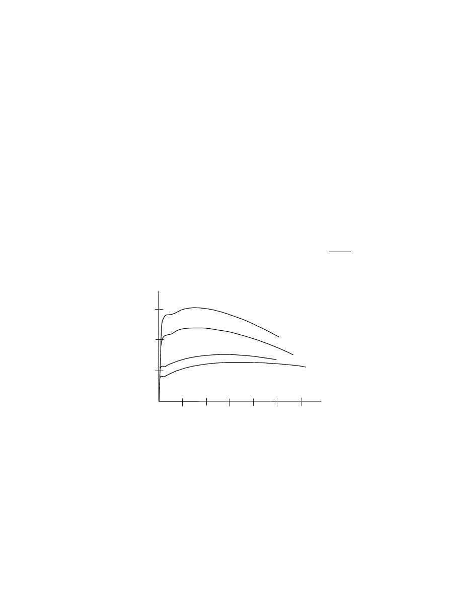
The ASTM specification for structural rivets, A502,
provided three grades, 1, 2, and 3 [10]. Grade 1 is a
carbon steel rivet for general structural purposes, Grade 2
is for use with higher strength steels, and Grade 3 is
similar to Grade 2 but has atmospheric corrosion resistant
properties. The only mechanical property specified for
rivets is hardness. The stress vs. strain relationship for the
two different strength levels is shown in Fig. 1.1, along
with those of bolt grades to be discussed later. (The plot
shown in Fig. 1.1 represents the response of a coupon
taken from the parent rivet or bolt.) Since the only reason
for dealing with rivet strength today is in the evaluation
of an existing structure, care must be taken to ascertain
the grade of the rivets in the structure. Very old structures
might have rivet steel of lesser strength than that reflected
by ASTM A502. (This ASTM standard, A502, was
discontinued in 1999.)
In fabricated structural steel applications, threaded
elements are encountered as tension rods, anchor rods,
and structural bolts. In light construction, tension
members are often made of a single rod, threaded for a
short distance at each end. A nut is used to effect the load
transfer from the rod to the next component. The weakest
part of the assembly is the threaded portion, and design is
based on the so-called "stress area." The stress area is a
defined area, somewhere between the cross-sectional area
through the root of the threads and the cross-sectional
area corresponding to the nominal bolt diameter. In the
US Customary system of units, this stress area (
st
A
) is
calculated as—
2
st
n
9743
.
0
D
7854
.
0
A
−
=
(1.1)
where D is the bolt diameter, inches, and n is the number
of threads per inch.
Threaded rods are not a factory-produced item, as is
the case for bolts. As such, a threaded rod can be made of
any available steel grade suitable for the job.
Anchor rods are used to connect a column or beam
base plate to the foundation. Like tension members, they
are manufactured for the specific task at hand. If hooked
or headed, only one end is threaded since the main
portion of the anchor rod will be bonded or secured
mechanically into the concrete of the foundation.
Alternatively, anchor rods can be threaded at both ends
A490 bolts
A502 grade 2 rivets
A502 grade
1 rivets
0.08
0.16
0.24
50
100
150
Strain
Stress
ksi
Fig. 1.1 Stress vs. Strain of Coupons taken from Bolts and Rivets
A325 bolts
3
and a nut used to develop the anchorage. Like threaded
rods, anchor rods can be made of any grade of steel. One
choice, however, is to use steel meeting ASTM A307,
which is a steel used for bolts, studs, and other products
of circular cross-section.
1
It is discussed below.
Structural bolts are loosely classified as either
common or high-strength. Common bolts, also known as
unfinished, ordinary, machine, or rough bolts, are covered
by ASTM Specification A307 [11]. This specification
includes the products known as studs and anchor bolts.
(The term stud is intended to apply to a threaded product
that will be used without a nut. It will be screwed directly
into a component part.) Three grades are available in
ASTM A307—A, B, and C. Grade B is designated for use
in piping systems and will not be discussed here. Grade A
has a minimum tensile strength of 60 ksi, and is intended
for general applications. It is available in diameters from
¼ in. to 1½ in. Grade C is intended for structural
anchorage purposes, i.e., non-headed anchor rods or
studs. The diameter in this grade can be as large as 4 in.
Structural bolts meeting ASTM A307 are sometimes used
in structural applications when the forces to be transferred
are not particularly large and when the loads are not
vibratory, repetitive, or subject to load reversal. These
bolts are relatively inexpensive and are easily installed.
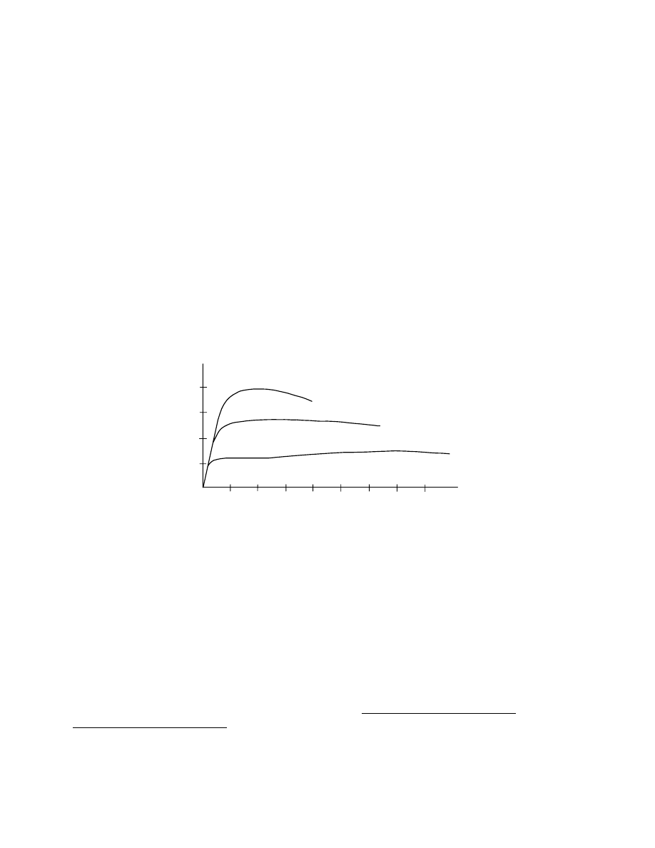
The response of an ASTM A307 bolt in direct tension is
shown in Fig. 1.2, where it is compared with the two
types of high-strength bolts used in structural practice.
The main disadvantages of A307 bolts are its inferior
strength properties as compared with high-strength bolts
and the fact that the pretension (if needed for the type of
joint) will be low and uncertain.
1
ASTM F1554 –99 (Standard Specification for Anchor
Bolts, Steel, 36, 55, and 105–ksi Yield Strength) is
probably a more common choice today, however.
Two strength grades of high-strength steel bolts are
used in fabricated structural steel construction. These are
ASTM A325 [12] and ASTM A490 [13]. Structural bolts
manufactured according to ASTM A325 can be supplied
as Type 1 or Type 3 and are available in diameters from
½ in. to 1½ in. (Type 2 bolts did exist at one time but
have been withdrawn from the current specification.)
Type 1 bolts use medium carbon, carbon boron, or
medium carbon alloy steel. Type 3 bolts are made of
weathering steel and their usual application is in
structures that are also of weathering steel. A325 bolts are
intended for use in structural connections that are
assembled in accordance with the requirements of the
Research Council on Structural Connections Specification
(RCSC) [14]. This link between the product specification
(ASTM A325) and the use specification (RCSC) is
explicitly stated in the ASTM A325 Specification. The
minimum tensile strength of A325 bolts is 120 ksi for
diameters up to and including 1 in. and is 105 ksi for
diameters beyond that value.
2
The other high-strength fastener for use in fabricated
structural steel is that corresponding to ASTM A490. This
fastener is a heat-treated steel bolt of 150 ksi minimum
tensile strength (and maximum tensile strength of
170 ksi). As with the A325 bolt, it is intended that A490
bolts be used in structural joints that are made under the
RCSC Specification. Two grades are available, Type 1
and Type 3. (As was the case with A325 bolts, Type 2
A490 bolts were available in the past, but they are no
longer manufactured.) Type 1, available in diameters of ½
to 1½ in., is made of alloy steel. Type 3 bolts are
atmospheric corrosion resistant bolts and are intended for
2
The distinction of strength with respect to diameter
arose from metallurgical considerations. These
metallurgical restrictions no longer exist, but the
distinction remains.
0.05
80
elongation (inches)
bolt
tens
ion (
ki
ps)
Fig. 1.2 Comparison of Bolt Types: Direct Tension
60
40
20
0.10
0.15
0.20
7/8 in. dia. A490 bolt
7/8 in. dia. A325 bolt
7/8 in. dia. A307 bolt
4
use in comparable atmospheric corrosion resistant steel
components. They also can be supplied in diameters from
½ to 1½ in.
Both A325 and A490 bolts can be installed in such a
way that a large pretension exists in the bolt. As will be
seen, the presence of the pretension is a factor in some
types of joints. This feature, and the concomitant
requirements for installation and inspection, are discussed
later.
There are a number of other structural fasteners
covered by ASTM specifications, for example A193,
A354, and A449. The first of these is a high-strength bolt
for use at elevated temperatures. The A354 bolt has
strength properties similar to that of the A490 bolt,
especially in its Grade BD, but can be obtained in larger
diameters (up to 4 in.) than the A490 bolt. The A449 bolt
has strength properties similar to that of the A325 bolt,
but it also can be furnished in larger diameters.
3
It is often
the specification used for high-strength anchor rods.
Overall, however, A325, and A490 bolts are used in the
great majority of cases for joining structural steel
elements.
The nuts that accompany the bolts (and washers, if
required) are an integral part of the bolt assembly.
Assuming that the appropriate mechanical fit between the
3
Although the A354 and the A449 bolts have strength
properties similar to the A325 and A490 bolts
respectively, the thread length, quality assurance
requirements, and packaging differ.
bolt and the nut has been satisfied, the main attribute of
the nut is that it have a strength consistent with that of the
bolt. Principally, this means that the nut must be strong
enough and have a thread engagement deep enough so
that it can develop the strength of the bolt before the nut
threads strip.
4
For the structural engineer, the selection of
a suitable nut for the intended bolt can be made with the
assistance of ASTM A563, Standard Specification for
Carbon and Alloy Steel Nuts [15]. A table showing nuts
suitable for various grades of fasteners is provided in that
Specification. Washers are described in ASTM F436 [16].
The RCSC Specification [14] provides summary
information for both nut and washer selection.
1.4. Types of Connections
It is convenient to classify mechanically fastened joints
according to the types of forces that are produced in the
fasteners. These conditions are tension, shear, and
combined tension and shear. In each case, the force can
be induced in several different ways.
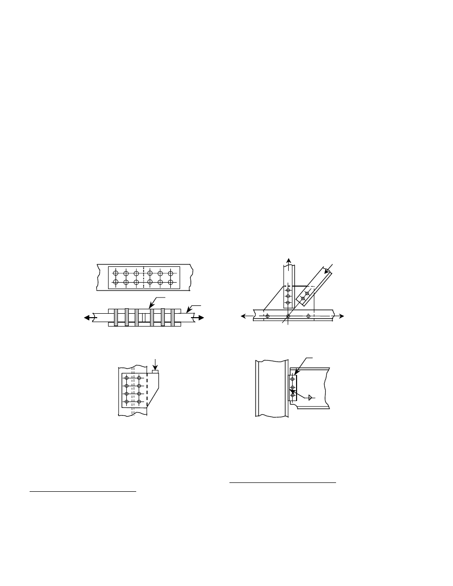
Figure 1.3 shows a number of different types of
joints that will produce shear in the fasteners. Part (a)
shows a double lap splice. The force in one main
component, say the left-hand plate, must be transferred
4
Strictly speaking, this is not always required. If the only
function of the bolt is to transfer shear, then the nut only
needs to keep the bolt physically in place. However, for
simplicity, the nut requirement described is applied to all
bolting applications.
Fig. 1.3(b) Truss Joint
lap plates
main
plate
Fig.1.3(a) Lap Splice
Fig. 1.3(c) Eccentric Joint
Fig. 1.3 Bolted Joint Configurations
Fig. 1.3(d) Standard Beam Connection
two angles
5
into the other main component, the right-hand plate. In
the joint illustrated, this is done first by transferring the
force in the left-hand main plate into the six bolts shown
on the left-hand side of the splice. These bolts act in
shear. Next, these six bolts transfer the load into the two
splice plates. This transfer is accomplished by the bearing
of the bolts against the sides of the holes in the plates.
5
Now the load is in the splice plates, where it is resisted by
a tensile force in the plate. Next, the load is transferred
out of the splice plates by means of the six bolts shown
on the right-hand side of the splice and into the main plate
on the right-hand side. In any connection, understanding
the flow of forces is essential for proper design of the
components, both the connected material and the
fasteners. In the illustration, this visualization of the force
flow (or, use of free-body diagrams!) allows the designer
to see, among other things, that six fasteners must carry
the total force at any given time, not twelve. More
complicated arrangements of splice plates and use of
different main components, say, rolled shapes instead of
plates, are used in many practical applications. The
problem for the designer remains the same, however—to
understand the flow of forces through the joint.
Part (b) of Fig. 1.3 shows a panel point connection in
a light truss. The forces pass out of (or into) the members
and into (or out of) the gusset plate by means of the
fasteners. These fasteners will be loaded in shear.
Fig. 1.3 (c) shows a crane rail bracket. The fasteners
again will be subjected to shear, this time by a force that
is eccentric relative to the center of gravity of the fastener
group. The standard beam connection (Fig. 1.3 (d))
provides another illustration of fasteners that will be
loaded in shear. There are numerous other joint
configurations that will result in shear in the fasteners.
5
Load transfer can also be by friction. This is discussed
in Section 5.2.
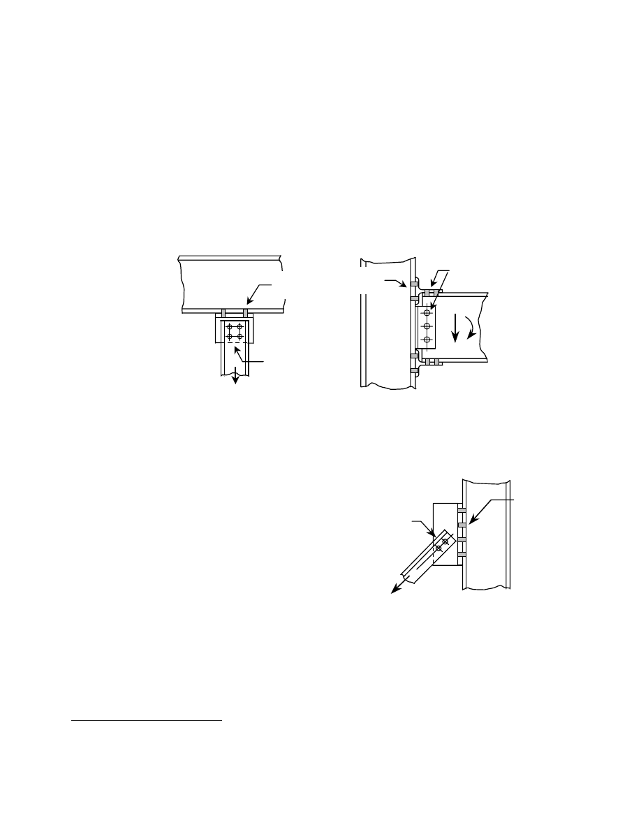
A joint in which tension will be induced in some of
the fasteners is shown in Fig. 1.4 (a). This is the
connection of a hanger to the lower flange of a beam.
Figure 1.4 (b) shows a beam-to-column connection in
which it is desired that both shear and moment be
transmitted from the beam to the column. A satisfactory
assumption for design is that all the shear force in the
beam is in the web and all the beam moment is in the
flanges. Accordingly, the fasteners in the pair of clip
angles used to transfer the beam shear force are
themselves loaded in shear. The beam moment
(represented by a force couple located at the level of the
flanges) is transmitted by the short tee sections that are
fastened to the beam flanges. The connection of the tee
section to the beam flanges puts those fasteners into
shear, but the connection of the top beam flange tee to the
column flange puts those fasteners into tension.
Finally, one illustration is presented where both shear
and tension will be present in the fasteners. The inclined
bracing member depicted in Fig. 1.5, shown as a pair of
angles, is a two-force member. Considering the tension
case, resolution of the inclined tensile force into its
horizontal and vertical components identifies that the
fasteners that connect the tee to the column must resist the
applied forces in both shear and in tension.
Fig. 1.4 Examples of Bolts in Tension
Fig. 1.4(a)
bolts in
tension
bolts in
shear
Fig. 1.4(b)
bolts in
shear
bolts in
tension
Fig. 1.5 Bolts in Combined Shear
and Tension
bolts in
combined
shear and
tension
bolts in
shear
6
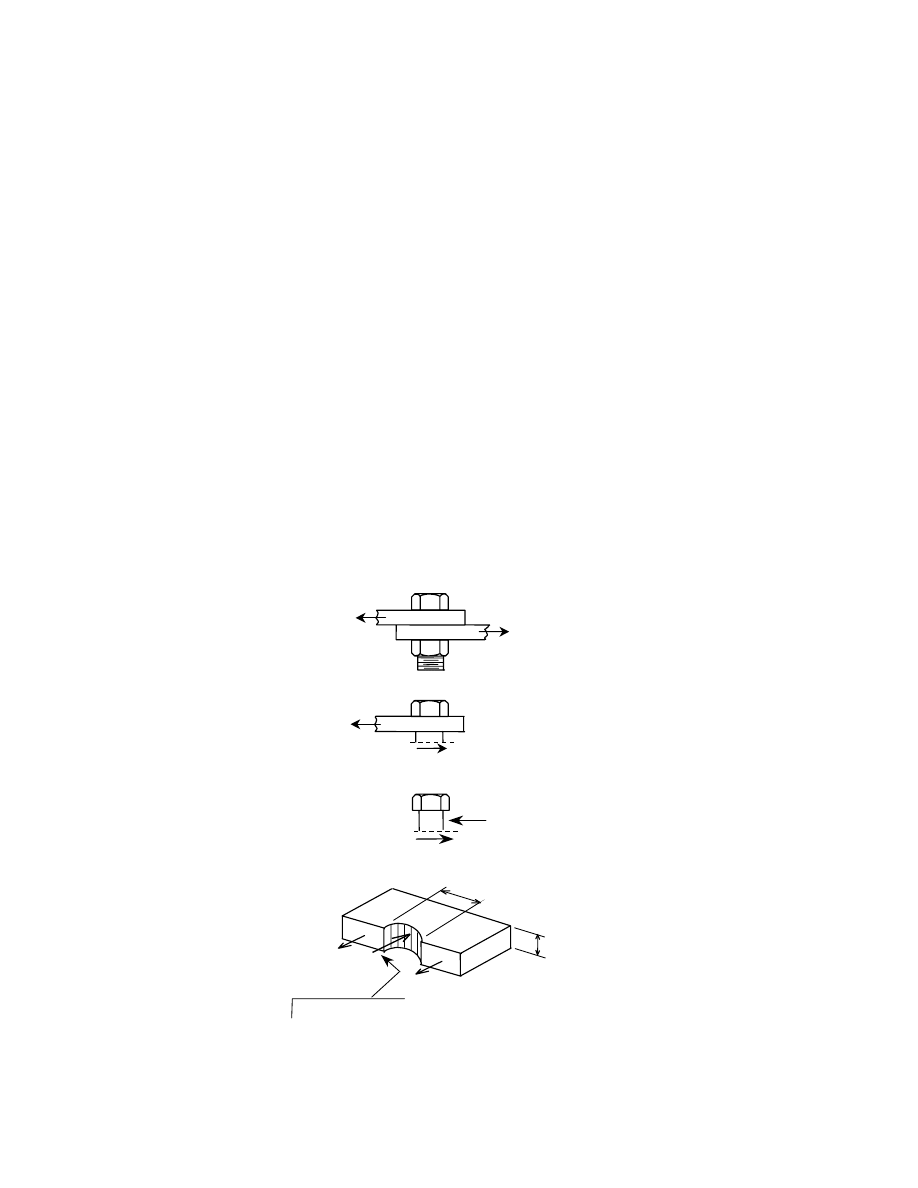
The example of load transfer that was demonstrated
by Fig. 1.3 (a) can be taken one step further, as is
necessary to establish the forces and corresponding
stresses in the connected material. Figure 1.6 shows the
same joint that was illustrated in Fig. 1.3 (a), except that it
has been simplified to one bolt and two plates. Part (a)
shows the joint. A free-body diagram obtained when the
bolt is cut at the interface between the two plates is shown
in Fig. 1.6 (b). (A short extension of the bolt is shown for
convenience.) For equilibrium, the force in the plate, P,
must be balanced by a force in the bolt, as shown. This is
the shear force in the bolt. If necessary, it can be
expressed in terms of the average shear stress,
τ , in the
bolt by dividing by the cross-sectional area of the bolt.
Going one step further, the bolt segment is isolated in Fig.
1.6 (c). This free-body diagram shows that, in order to
equilibriate the shear force in the bolt, an equal and
opposite force is required. The only place this can exist is
on the right-hand face of the bolt. This force is delivered
to the bolt as the top plate pulls up against the bolt, i.e.,
the bolt and the plate bear against one another. Finally,
the short portion of the top plate to the right of the bolt,
Fig. 1.6 (a), is shown in Fig. 1.6 (d). The force identified
as a "bearing force" in Fig. 1.6 (c) must be present as an
equal and opposite force on the plate in part (d) of the
figure. This bearing force in the plate can be expressed as
a stress, as shown, if that is more convenient. Finally,
since the plate segment must be in equilibrium, the pair of
forces, P/2, must be present in the plate.
These are simple illustrations of how some
connections act and the forces that can be present in the
bolts and in the adjacent connected material. There are
some other cases in which the load transfer mechanism
needs to be further explained, for example, when
pretensioned high-strength bolts are used. This will be
done in later chapters.
1.5. Design Philosophy
For fabricated steel structures, two design philosophies
coexist at the present time in the United States—limit
states design and allowable stress design. In limit states
design, commonly designated in the United States as
Load and Resistance Factor Design, it is required that the
"limit states" of performance be identified and compared
with the effect of the loads applied to the structure. The
limit states are considered to be strength and
serviceability.
In the United States, the most commonly used
specifications for the design of steel buildings are those of
the American Institute of Steel Construction. In limit
states design format, the AISC Load and Resistance
Factor Design Specification (LRFD) is used [17]. If
Fig. 1.6 (a)
P
P
Fig.1.6 Bolt Forces and Bearing in Plate
P/2
P/2
P
t
d
note that this force is equal and
opposite to the bearing force shown
in (c)
associated average
bearing stress:
σ = P/A = P/(txd)
Q
.
Q
.
Fig. 1.6 (d)
P
P a bearing force
{
Fig. 1.6 (c)
P
P
(and associated shear stress,
τ = P/A)
Q
.
Fig. 1.6 (b)
.
Q

7
allowable stress design (ASD) is used, then the AISC
Specification for Structural Steel Buildings, Allowable
Stress Design and Plastic Design, is available [18].
An example of a strength limit state is the
compression buckling strength of an axially loaded
column. The design strength is calculated according to the
best available information, usually as expressed by a
Specification statement of the nominal strength, which is
then reduced by a resistance factor. The resistance factor,
φ
, is intended to account for uncertainties in the
calculation of the strength, understrength of material,
level of workmanship, and so on. In LRFD terminology,
the product of the calculated ultimate capacity and the
resistance factor is known as the design strength.
The loads that act on the structure are likewise
subject to adjustment: few, if any, loads are deterministic.
Therefore, the expected loads on a structure are also
multiplied by a factor, the load factor. (More generally,
load factors are applied in defined combinations to
different components of the loading.) For most
applications, the load factor is greater than unity. Finally,
the factored resistance is compared with the effect of the
factored loads that act on the structure.
In allowable stress design, the structure is analyzed
for the loads expected to be acting (nominal loads) and
then stresses calculated for each component. The
calculated stress is then compared with some permissible
stress. For example, a fraction of the yield stress of the
material is used in the case of a tension member.
It is interesting to note that, for a long time, the
design of mechanical fasteners has been carried out using
a limit states approach. Even under allowable stress
design, the permissible stress was simply a fraction of the
tensile strength of the fastener, not a fraction of the yield
strength. Indeed, it will be seen that there is no well-
defined yield strength of a mechanical fastener: the only
logical basis upon which to design a bolt is its ultimate
strength.
The other limit state that must be examined is
serviceability. For buildings, this means that such things
as deflections, drift, floor vibrations, and connection slip
may have to be examined. In contrast to the situation
when the ultimate limit state is under scrutiny, these
features are to be checked under the nominal loads, not
the factored loads.
One of the most important features of bridge design
(and other structures subjected to moving or repetitive
loads) is fatigue. Some specifications put this topic in the
category of ultimate limit state, whereas others call it a
serviceability limit state. The principal design
specification for fatigue in highway bridges in the United
States, the rules of the American Association of State
Highway and Transportation Officials (AASHTO),
creates a separate limit state for fatigue [19]. This is done
primarily because the so-called fatigue truck, used to
calculate stresses for the fatigue case, does not correspond
to either the nominal load or to the usual factored load.
A full discussion of allowable stress design and limit
states design can be found in most books on the design of
fabricated steel structures. See, for example, Reference
[20].
1.6. Approach Taken in this Primer
In this document, the usual approach is to describe the
phenomenon under discussion in general terms, provide
enough background information by way of research or, in
some cases, theoretical findings, to enable a description
of the phenomenon to be made, and then to provide a
design rule. This is then linked to the corresponding rule
in the principal specification, that of AISC [17], and only
the LRFD rules will be discussed. In a few cases, the
reference specification will be that of AASHTO [19].


9
Chapter 2
STATIC STRENGTH of RIVETS
2.1 Introduction
As discussed in Chapter 1, rivets have not been used in
the fabrication and erection of structural steel for many
years. However, there are still reasons why a structural
engineer may need to know about the behavior of rivets.
Because they can be present in existing buildings and
bridges, it follows that one objective is the necessity of
evaluating the strength of these elements when a structure
is considered for such things as renovation or the
determination of safety under increased load levels. In
this Chapter, the static design strength of rivets is
examined. The fatigue strength of a riveted connection,
the other major area of interest, is more logically treated
in Chapter 7, Fatigue of Bolted and Riveted Joints.
2.2 Rivets Subject to Tension
The tensile stress vs. strain response for ASTM A502
rivet steel (i.e., undriven rivets) was shown in Fig. 1.1.
The tensile strength is about 60 ksi for Grade 1 and about
80 ksi for Grade 2 or 3. After the rivet has been driven,
the tensile strength can be significantly increased [21]. At
the same time, however, the ductility of the driven rivet is
considerably less than that of the material from which it
was driven. Most tension tests of driven rivets also show
a decrease in strength with increasing rivet length (grip).
The residual clamping force that is present in a driven
rivet does not affect the ultimate strength of the rivet. In
principle then, the design tensile strength of a rivet is
simply the product of the minimum tensile strength of the
rivet material multiplied by a resistance factor.
The AISC LRFD Specification provides rules for the
design tension strength (
n
R
φ
) of ASTM A502 rivets. In
accordance with Article J3.6 of the Specification, this is
to be calculated as:
b
t
n
A
F
R
φ
=
φ
(2.1)
where
n
R
φ
= design tension strength in tension, kips
φ = resistance factor, taken as 0.75
t
F
= nominal tensile strength, taken as 45 ksi for
ASTM A502 Grade 1 hot-driven rivets or as
60 ksi for Grade 2 hot-driven rivets
b
A
= cross-sectional area of the rivet according to
its nominal diameter, in.
2
The product
b
t
A
F
obviously is the ultimate tensile
strength (nominal strength) of the rivet shank. The value
of the resistance factor
φ recommended in the AISC
Specification, 0.75, is relatively low, as it is for most
connection elements. There is no research available that
identifies the appropriate value of the resistance factor,
φ , for rivets in tension. However, the case of high-
strength bolts in tension can be used as a basis of
comparison. In Reference [22], it was established that
85
.
0
=
φ
is a satisfactory choice for high-strength bolts in
tension. This is also the value recommended in the Guide
[6]. Thus, selection of the value 0.75 is a conservative
choice for rivets, but it results in values that are consistent
with those used historically in allowable stress design.
It is not uncommon for mechanical fasteners acting in
tension to be loaded to a level that is greater than that
corresponding to the total applied load divided by the
number of fasteners. This is the result of prying action
produced by deformation of the connected parts. It is
advisable to follow the same rules for prying action in the
case of rivets in tension as are recommended for bolts in
tension. Prying action is discussed in Chapter 6.
The most common need for the strength calculation
of a rivet or rivet group in tension will be to determine the
strength of an existing connection. The integrity of the
rivet heads should be closely examined. If the head is not
capable of resisting the force identified in Eq. 2.1, then
the calculation simply is not valid. Rivet heads in such
structures as railroad bridges can be severely corroded as
a result of the environmental conditions to which they
have been subjected over the years.
2.3 Rivets in Shear
Numerous tests have been carried out to determine the
shear strength of rivets—see, for example, References
[21, 23, 24]. These tests all show that the relationship
between the shearing force that acts on a rivet and its
corresponding shearing displacement has little, if any,
region that can be described as linear. Thus, the best
description of the strength of a rivet in shear is its
ultimate shear capacity. In order to be able to compare
rivets of different basic strengths, it is usual to relate the
shear strength to the tensile strength of the steel from
which the rivet is made. The results [21, 23] indicate that
the value of this ratio (shear strength / tensile strength) is
about 0.75, and that the ratio is not significantly affected
by the grade of rivet or whether the shear test was done
10
on driven or undriven rivets. However, there is a
relatively wide spread in the value of the ratio, from about
0.67 to 0.83, according to the work in References [21 and
23].
Typical shear load vs. shear deformation tests are
shown in Fig. 2.1 [25]. These tests are for 7/8 in. dia.
A502 Grade 1 rivets with two different grip lengths, 3 in.
and 4½ in. Because of greater bending in the longer rivets
(and un-symmetrical loading in the case of these tests),
there was greater deformation in these rivets in the early
stages of the test. However, the ultimate shear strength
was unaffected by grip length. Since driving of the rivet
increases its tensile strength, the corresponding shear
strength is likewise expected to increase. Thus, the shear
strength of Grade 1 A502 rivets can be expected to be at
least
ksi
45
=
ksi
60
0.75
×
and that for Grade 2 or
Grade 3 rivets will be about
ksi
60
=
ksi
80
0.75
×
. (The
multiplier 0.75 is not a resistance factor. It is the value of
the ratio shear strength
/
tensile strength mentioned
above.)
As was the case for rivets in tension, there have not
been any studies that have explored the resistance factor
for rivets in shear. The value recommended in the Guide
[6] for bolts in shear is 0.80. In Reference [22], the
resistance factor recommended is 0.83 for ASTM A325
bolts and 0.78 for ASTM A490 bolts.
In the AISC LRFD Specification, Section J3.6
requires that the design shear strength (
n
R
φ
) of a rivet is
to be taken as—
b
v
n
A
F
R
φ
=
φ
(2.2)
where
n
R
φ
= design shear strength, kips
φ = resistance factor, taken as 0.75
v
F
= nominal shear strength, taken as 25 ksi for
ASTM A502 Grade 1 rivets or as 33 ksi for
Grade 2 and Grade 3 hot-driven rivets
b
A
= cross-sectional area of the rivet,
2
.
in
The
calculation of
b
A
should reflect the number
of shear planes present.
Comparing the nominal shear strength values given
in the Specification for the two rivet grades (25 ksi or
33 ksi) with the corresponding experimentally determined
values (45 ksi or 60 ksi), it can be seen that the
permissible values under the AISC LRFD rules are
significantly conservative. When evaluating the shear
strength of rivets in an existing structure, these
conservative elements of the design rule can be kept in
mind.
The effect of joint length upon shear strength applied
to bolted shear splices (Section 5.1.) should also be
applied for long riveted connections. See also Section
J3.6 of the AISC LRFD Specification.
2.4 Rivets in Combined Shear and Tension
It was explained in Section 1.4 (and with reference to
Fig. 1.5) that fasteners must sometimes act under a
combination of tension and shear. Tests done by Munse
and Cox [23] form the basis for the design rule for this
case. The tests were done on ASTM A141 rivets (which
are comparable to A502 Grade 1 rivets), but the results
are considered to be reasonable for application to all
grades of rivets. The test variables included variation in
grip length, rivet diameter, driving procedure, and
manufacturing process [23]. The only one of these
variables that had an influence on the behavior was grip
length: long grip rivets tended to show a decrease in
strength with length. This is consistent with tests done on
rivets loaded in shear only. As the loading condition
changed from tension-only to shear-only, deformation
capacity decreased. This also is consistent with
observations for rivets in tension and rivets in shear.
An elliptical interaction curve was fitted to the test
results [23]. The mathematical description of the curve is:
(
)
0
.
1
y
75
.
0
x
2
2
2
=
+
(2.3)
where x = ratio of calculated shear stress )
(
τ to tensile
strength of the rivet
)
(
u
σ
(i.e.,
u
/
x
σ
τ
=
)
y = ratio of calculated tensile stress
)
(
σ
to tensile
strength of the rivet
)
(
u
σ
(i.e.,
u
/
y
σ
σ
=
)
An alternative representation of the test results was
also suggested by the researchers [26]. This form, which
20
40
60
0.05
0.10
0.15
0.20
0.25
4-½ in. grip
3 in.
grip
Deformation (in.)
Load
(kips)
Fig. 2.1 Shear vs. Deformation Response of
A502 Grade 1 Rivets

11
approximates the elliptical interaction equation with three
straight lines, is the model used in the AISC LRFD
Specification. In the AISC Specification (Table J3.5),
A502 rivets of Grade 1 are permitted a nominal tension
stress (ksi) under conditions of combined tension and
shear of
45
f
4
.
2
59
F
v
t
≤
−
=
(2.4)
and for A502 Grade 2 and 3 rivets, the expression is:
60
f
4
.
2
78
F
v
t
≤
−
=
(2.5)
Equations 2.4 and 2.5 use the AISC LRFD notation
for stresses. The resistance factor
75
.
0
=
φ
must be
applied to the result obtained by Equation 2.4 or 2.5, and
then the design tension strength of the rivet (now reduced
by the presence of shear) can be determined using
Equation 2.1.
In applying these rules, it is apparent that the nominal
tensile stress is limited to the nominal tensile strength of
the rivet, which is 45 ksi for Grade 1 and 60 ksi for Grade
2 and 3. It should be remembered, as well, that there is
also a limit on the calculated shear stress,
v
f
(computed
under the factored loads). It must be equal to or less than
the nominal shear strength multiplied by the resistance
factor. The nominal shear stress is 25 ksi for A502
Grade 1 rivets and 33 ksi for Grade 2 and 3 rivets.
An advantage of the straight-line representation is
that it identifies the range of shear stress values for which
a reduction in tensile strength needs to be made. For
example, a reduction in tensile strength for Grade 1 rivets
is required when the calculated shear stress under the
factored loads is between 5.8 ksi and the maximum
permitted value of 18.8 ksi (i.e., 25 ksi
φ
×
= 0.75). At
the former, the nominal tensile stress is, of course, 45 ksi,
and at the latter it has been reduced to 21.5 ksi.
The elliptical representation and the straight-line
representation fit the test data about equally well when
the forms presented in Reference [26] are applied. In the
formulation used by AISC (Equations 2.4 and 2.5 above),
the result will be conservative. It has already been pointed
out in this Chapter that the rules given in the AISC LRFD
Specification for the tension-only and the shear-only
cases are themselves conservative.


13
Chapter 3
INSTALLATION OF BOLTS AND THEIR INSPECTION
3.1 Introduction
The installation of bolts, both high-strength bolts and
common bolts, is presented in this chapter. This is
accompanied by information on the inspection process
that is necessary to ensure that the expectations of the
installation have been met. Further information on the
physical characteristics and mechanical properties of bolts
is also included.
High-strength bolts can be installed in a way such
that an initial pretension (or, preload) is present. The
installation of ordinary bolts (ASTM A307) does not
result in any significant pretension. For some
applications, the presence of a pretension affects how the
joint performs, and the inspection of installation of high-
strength bolts should reflect whether or not bolt
pretension is required. Whether bolts should be
pretensioned is important in both the installation and
inspection processes. Because of this importance, advice
is given as to when pretensioned bolts should be required.
3.2 Installation of High-Strength Bolts
A bolt is a headed externally threaded fastener, and it is
intended to be used with a nut. High-strength bolts were
introduced in Section 1.3, and for structural applications
two types of bolts are used—ASTM A325 and ASTM
A490. Washers may or may not be required (see
Chapter 8), depending on the application. Both the bolt
head and the nut are hexagonal. The shank is only
partially threaded, and the threaded length depends on the
bolt diameter. Complete information on these details can
be obtained in the relevant specifications [12, 13].
Not all structural bolts used in practice precisely meet
the definition just given. Two other bolt configurations
are in common use. These are bolts that meet or replicate
the ASTM A325 or A490 requirements, but which have
special features that relate to their installation. One is the
"twist-off" bolt, which is covered by ASTM Specification
F1852. It is described in Section 3.2.4. The other case is
different from the conventional bolt–nut set only by the
addition of a special washer that acts as an indicator of the
pretension in the bolt. Its installation and other
characteristics are described in Section 3.2.5.
Bolts meeting the requirements of ASTM Standards
A325 and A490 were first described in Section 1.3. It was
noted there that the ultimate tensile strength level for
A325 bolts is 120 ksi or 105 ksi. The former applies to
bolts of diameter up to and including 1 in. and the latter
for bolts greater than 1 in. diameter. There is no
maximum ultimate tensile strength specified for A325
bolts. The other kind of high-strength bolt used in
structural practice, ASTM A490, has a specified ultimate
tensile strength of 150 ksi (and a maximum tensile
strength of 170 ksi) for all diameters. In each case, the
mechanical requirements of the specifications also make
reference to a so-called proof load. This is the level up to
which the bolt can be loaded and then unloaded without
permanent residual deformation. In mild structural steels,
this is termed the yield strength. However, in the case of
the high-strength bolts there is no well-defined yield
strength and all the design strength statements for high-
strength bolts use the ultimate tensile strength as the basic
parameter. Hence, the designer need not be concerned
about the proof load.
It is required that the nuts for high-strength bolts used
in normal structural applications are heavy hex nuts that
conform to the requirements of ASTM Standard A563
[15]. (If the bolts are to be used in high-temperature or
high-pressure applications, then another ASTM Standard
is used for identifying the appropriate nuts.) When zinc-
coated A325 bolts are to be used, then the nuts must also
be galvanized and tapped oversize. In this case,
requirements for lubrication of the nuts and a rotation
capacity test for the bolt–nut assembly are specified in
ASTM Standard A325. (This is discussed in Section 8.5.)
Bolts are installed by first placing them in their holes
and then running the nut down on the bolt thread until it
contacts the connected plies. This can be done either
manually, by using a spud wrench,
1
or using a power tool,
which is usually a pneumatic impact wrench. The
expectation is that the connected parts will be in close
contact, although in large joints involving thick material it
cannot be expected that contact is necessarily attained
completely throughout the joint. The installation process
should start at the stiffest part of the joint and then
progress systematically. Some repetition may be required.
The condition of the bolts at this time is referred to as
snug-tight, and it is attained by the full effort of the
ironworker using a spud wrench or by running the nut
down until the air-operated wrench first starts to impact.
The bolt will undergo some elongation during this
process, and there will be a resultant tensile force
developed in the bolt. In order to maintain equilibrium, an
equal and opposite compressive force is developed in the
connected material. The amount of the bolt tension at the
1
A spud wrench is the tool used by an ironworker to
install a bolt. It has an open hexagonal head and a tapered
handle that allows the worker to insert it into holes for
purposes of initial alignment of parts.
14
snug-tightened condition is generally large enough to hold
the parts compactly together and to prevent the nut from
backing off under static loads. As an example, in
laboratory tests snug-tight bolt pretensions range from
about 5 to 10 kips for 7/8 in. diameter A325 bolts. In
practice, the range is probably even larger.
For many applications, the condition of snug-tight is
all that is required. Because use of snug-tightened bolts is
an economical solution, they should be specified
whenever possible. If the function of the joint requires
that the bolts be pretensioned, then bolt installation must
be carried out in one of the ways described following.
Whether or not the bolts need to be pretensioned is
described in Section 3.3.
3.2.1 Turn-of-Nut
Installation
If the nut continues to be turned past the location
described as snug-tight, then the bolt tension will continue
to increase. In this section, the installation process
described is that in which a prescribed amount of turn of
the nut is applied. This is an elongation method of
controlling bolt tension. Alternatively, a prescribed and
calibrated amount of torque can be applied, as described
in Section 3.2.2.
As the nut is turned, conditions throughout the bolt
are initially elastic, but local yielding in the threaded
portion soon begins. Most of the yielding takes place in
the region between the underside of the nut and the thread
run-out. As the bolt continues to elongate under the action
of turning the nut, the bolt load (pretension) vs.
elongation response flattens out, that is, the bolt
pretension force levels off.
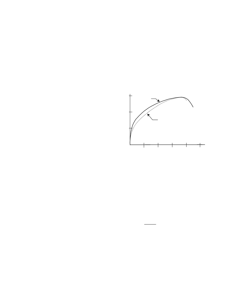
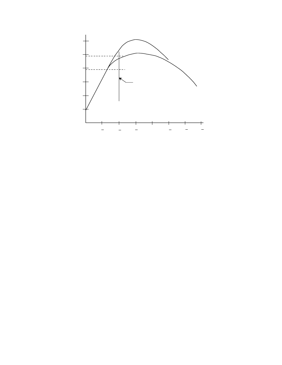
Figure 3.1 shows the bolt pretension obtained by
turning the nut on a certain lot of A325 bolts [27]. These
were 7/8 in. diameter bolts that used a grip length of 4–
1/8 in. (In this laboratory study, the snug-tight condition
was uniquely established for all bolts in the lot by setting
the snug-tight load at 8 kips.) It can be seen that the
average response is linear up to a load level slightly
exceeding the specified proof load, then yielding starts to
occur in the threads and the response curve flattens out.
Also shown in the figure is the range of elongations that
were observed at 1/2 turn past snug, which is the RCSC
Specification requirement [14] for bolts of the length used
in this study. The specified minimum bolt pretension is 39
kips for A325 bolts of this diameter, and it can be
observed that the measured pretension at 1/2 turn is well
above this value. (The minimum bolt pretension required
is 70% of the minimum specified ultimate tensile strength
of the bolt [14].)
Figure 3.1 also shows that the specified minimum
tensile strength of the bolt (i.e., direct tension) is well
above the maximum bolt tension reached in the test (i.e.,
torqued tension). This reflects the fact that during
installation the bolts are acting under a condition of
combined stresses, tension and torsion.
The results of the bolt installation shown in Fig. 3.1,
which is typical of turn-of-nut installations, raise the
following questions:
• How do such bolts act in joints, rather than
individually as depicted in Fig. 3.1?
• If the bolts subsequently must act in tension, can
they attain the specified minimum tensile strength?
• Does the yielding that takes place in the bolt
threads (mainly) affect the subsequent strength of
the bolt in shear, tension, or combined tension and
shear?
• What is the margin against twist-off of the bolts in
the event that more than 1/2 turn is applied
inadvertently?
• How sensitive is the final condition (e.g., bolt
pretension at 1/2 turn) to the level of the initial
pretension at snug-tight?
The first three items in the list apply to bolts installed
by any procedure: the others are specific to turn-of-nut
installations.
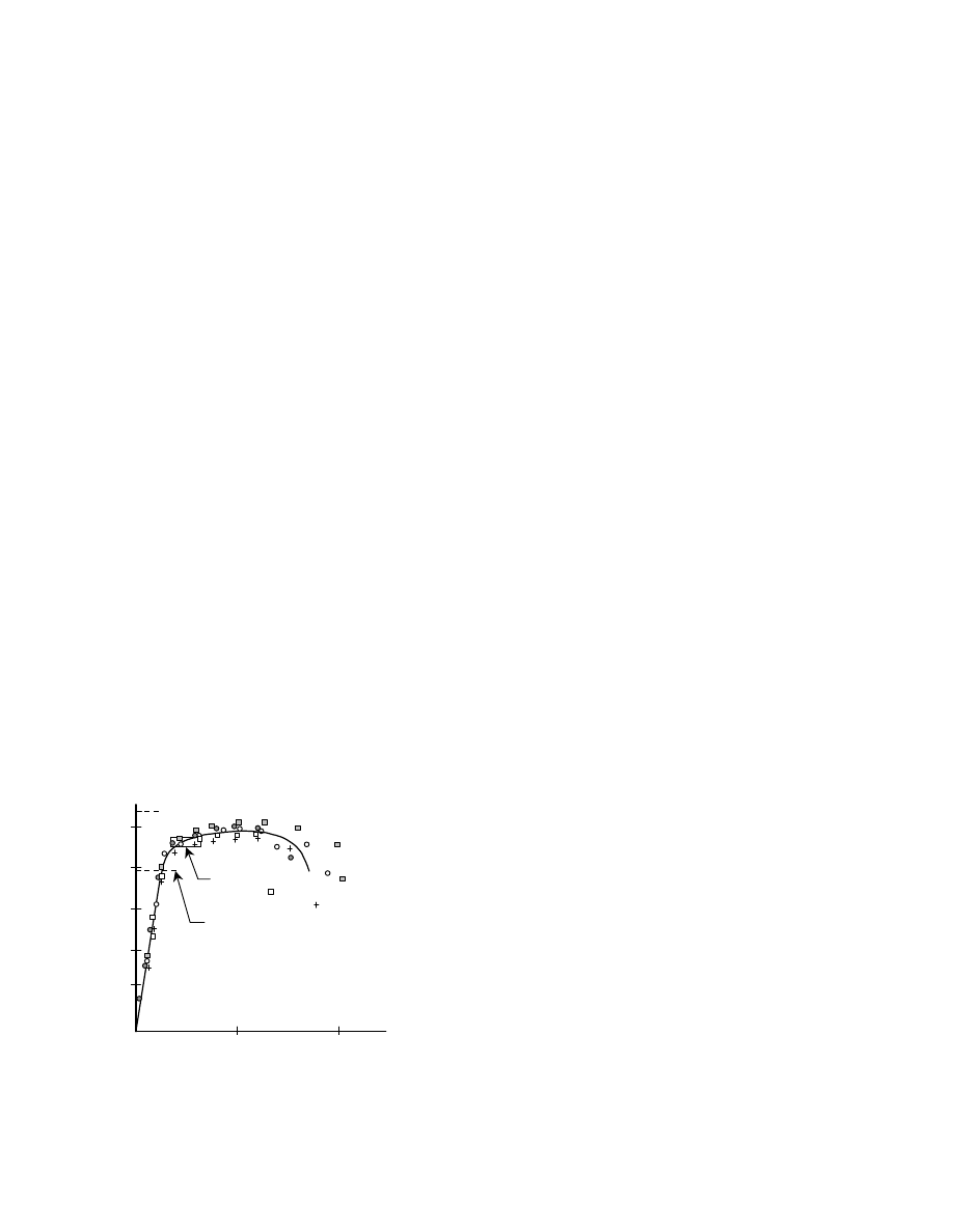
Several of these questions can be addressed by
looking at the behavior of bolts that were taken from the
same lot as used to obtain Fig. 3.1 when they were
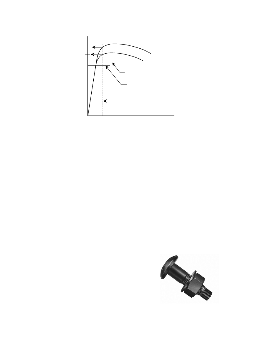
installed in a large joint [6]. Figure 3.2 shows the bolt
elongations and subsequent installed pretensions for 28 of
these bolts installed to 1/2 turn of nut beyond snug-tight.
The individual bolt pretensions can be estimated by
projecting upward from the bolt elongation histogram at
the bottom of the figure to the plot of bolt pretensions
obtained by the turn-of-nut installation. Even though there
is a large variation in bolt elongation for these 28 bolts
(from about 0.03 in. to nearly 0.05 in.), the resultant
pretension hardly varies at all. This is because the bolts
have entered the inelastic range of their response. Thus,
the turn-of-nut installation results in a reliable level of
Fig. 3.1 Load vs. Elongation Relationship, Torqued Tension
0.05
0.10
50
40
30
20
spec. min.
pretension
specified min. tensile strength
7/8 in. dia. A325 bolts
elongation (in.)
bolt
tension
(kips)
1/2 turn
of nut
10
15
bolt pretension and one that is consistently above the
minimum required bolt pretension.
The second thing that can be observed from Fig. 3.2
is that, even though the range of bolt pretension at the
snug condition was large (from about 16 kips to 36 kips),
the final pretension is not affected in any significant way.
Again, this is because the bolt elongation imposed during
the installation procedure has taken the fastener into the
inelastic region of its behavior.
It is highly unlikely that a high-strength bolt, once
installed, will be turned further than the prescribed
installation turn. Because of the extremely high level of
bolt pretension present, about 49 kips in the example of
Fig. 3.2, it would require considerable equipment to
overcome the torsional resistance present and further turn
the nut. In other words, it would require a deliberate act to
turn the nut further, and this is not likely to take place in
either bridges or buildings once construction has been
completed. It is possible, however, that an ironworker
could inadvertently apply more than the prescribed turn.
For instance, what is the consequence if a nut has been
turned to, say, 1 turn rather than to 1/2 turn?
The answer to this question is twofold. First, at 1 turn
of the nut the level of pretension in the bolt will still be
above the specified minimum pretension [6]. In fact, the
research shows that the pretension is likely to still be high
just prior to twist-off of the fastener. Second, the margin
against twist-off is large. Figure 3.3 shows how bolt
pretension varies with the number of turns of the nut for
two lots of bolts, A325 and A490, that were 7/8 in.
diameter and 5-1/2 in. long and had 1/8 in. of thread in the
grip [6]. The installation condition for this bolt length is
1/2 turn. It can be seen that it was not until about 1-3/4
turns that the A325 bolts failed and about 1-1/4 turns
when the A490 bolts failed. In other words, there is a
considerable margin against twist-off for both fastener
types.
It was observed in discussing the data in Fig. 3.1 that
the pretension attained by the process of turning a nut
onto a bolt does not reach the maximum load that can be
attained in a direct tension test of the bolt. The presence
of both tensile stresses and torsional stresses in the former
case degrades the strength. However, laboratory tests for
both A325 and A490 bolts [27, 28] show that a bolt
installed by the turn-of-nut method and then subsequently
loaded in direct tension only is able to attain its full direct
tensile strength. This is because the torsional stresses
introduced in the installation process are dissipated as the
connected parts are loaded and the contact stresses
decrease. Thus, bolts installed by turning on the nut
against gripped material can be proportioned for
subsequent direct tension loading on the basis of their
ultimate tensile strength.
The strength of bolts in shear is likewise unaffected
by the stresses imposed during installation. This is
elaborated upon in the discussion in Section 4.3, where
the strength of bolts in shear is described.
It will be seen in Section 4.4 that the design rule for
the capacity of bolts in combined tension and shear is an
interaction equation developed directly from test results.
Hence, the question as to how the strength might be
affected is not influenced by the pre-existing stress
conditions. In any event, since neither the direct tensile
strength nor the shear strength is affected by pretension, it
is unlikely that the combined torsion and shear case is
influenced.
The discussion so far has described bolts that are
installed to 1/2 turn past snug. In practice, this will indeed
0.02
0.08
0.06
0.04
20
40
60
bolt elongation (in.)
bolt elongation
at one-half turn
range of bolt
elongations at snug
bolt
tension
(kips)
bolt tension by turning the nut
specified minimum pretension
Fig. 3.2 Bolt Tension in Joint at Snug and at One-Half Turn of Nut
16
be the RCSC Specification requirement applicable in a
great many practical cases. However, for longer bolts, 1/2
turn may not be sufficient to bring the pretension up to the
desired level, whereas for shorter bolts 1/2 turn might
twist off the bolt. Laboratory studies show that for bolts
whose length is over eight diameters but not exceeding 12
diameters, 2/3 turn of the nut is required for a satisfactory
installation. For short bolts, those whose length is up to
and including four diameters, 1/3 turn of nut should be
applied. The bolt length is taken as the distance from the
underside of the bolt head to the extremity of the bolt. It is
expected that the end of the bolt will either be flush with
the outer face of the nut or project slightly beyond it. If
the combination of bolt length and grip is such that there
is a large "stick-through," then it is advisable to treat the
bolt length as the distance from the underside of the bolt
head to the outer face of the nut for the purpose of
selecting the proper turn to be applied.
These rules apply when the outer faces of the bolted
parts are normal to the axis of the bolts. Certain structural
steel shapes have sloped surfaces—a slope up to 1:20 is
permitted. When non-parallel surfaces are present, the
amount of turn-of-nut differs from those cases just
described. The exact amount to be applied depends upon
whether one or both surfaces are sloped. The RCSC
Specification should be consulted for these details.
Alternatively, beveled washers can be used to adjust the
surfaces to within a 1:20 slope, in which case the resultant
surfaces are considered parallel.
It is important to appreciate that the connected
material within the bolt grip must be entirely steel. If
material more compressible than steel is present, for
example if material for a thermal break were
contemplated, then the turn-of-nut relationships
developed for solid steel do not apply. Whatever the bolt
type and method of installation, the problems that can
arise have to do with the attainment and retention of bolt
pretension. The RCSC Specification simply takes the
position that all connected material must be steel.
Users of bolts longer than about 12 bolt diameters
should exercise caution: bolts of these lengths have not
been subjected to very much laboratory investigation for
turn-of-nut installation. The installation of such bolts
should be preceded by calibration tests to establish the
appropriate amount of turn of the nut.
Generally speaking, washers are not required for
turn-of-nut installations. The main exceptions are (a)
when non-parallel surfaces are present, as discussed
above, (b) when slotted or oversize holes are present in
outer plies, and (c) when A490 bolts are used to connect
material having a specified yield strength less than 40 ksi.
The use of slotted or oversized holes is discussed in
Section 8.3. The necessity for washers when A490 bolts
are used in lower strength steels arises because galling
and indentation can occur as a result of the very high
pretensions that will be present. If galling and indentation
take place under the bolt head or nut, the resultant
pretension can be less than expected. Use of hardened
washers under both the bolt head and the nut will
eliminate this problem. Further details are found in
Chapter 8.
It should also be observed that any method of
pretensioned installation, of which turn-of-nut is the only
one discussed so far, can produce bolt pretensions greater
than the specified minimum value. This is not a matter for
concern. Those responsible for the installation of high-
strength bolts and inspectors of the work should
understand that attainment of the "exact" specified value
minimum pretension
A325 bolts
minimum
pretension
A490 bolts
1/2 turn of nut
A325 bolts
A490 bolts
10
20
30
40
60
50
4
1
2
1
4
3
1
4
1
1
2
1
1
4
3
1
nut rotation, turns
bolt
tension
kips
Fig. 3.3 Bolt Load vs. Nut Rotation

17
of pretension is not the goal and that exceeding the
specified value is acceptable.
In summary, the use of the turn-of-nut method of
installation is reliable and produces bolt pretensions that
are consistently above the prescribed values.
3.2.2 Calibrated Wrench Installation
Theoretical analysis identifies that there is a relationship
between the torque applied to a fastener and the resultant
pretension [29]. It is therefore tempting to think that bolts
can successfully be installed to specified pretensions by
application of known amounts of torque. The relationship
between pretension and torque is a complicated one,
however, and it reflects such factors as the thread pitch,
thread angle and other geometrical features of the bolt and
nut, and the friction conditions between the various
components of the assembly. As a consequence, it is
generally agreed that derived torque vs. pretension
relationships are unreliable [6, 29]. The RCSC
Specification [14] is explicit upon this point. It states that,
"This Specification does not recognize standard torques
determined from tables or from formulas that are assumed
to relate torque to tension."
There is a role for a torque-based installation method,
however. Provided that the relationship between torque
and resultant bolt pretension is established by calibration,
then it becomes an acceptable method of installation. In
the RCSC Specification, this is known as the calibrated
wrench method of installation. What is required, then, is
to calibrate the torque versus pretension process under
conditions that include the controlling features described
above. In practice, this means that an air-operated
wrench
2
is used to install a representative sample of the
fasteners to be used in a device capable of indicating the
tension in the bolt as the torque is applied. Rather than
trying to identify the torque value itself, the wrench is
adjusted to stall at the torque corresponding to the desired
preload. The load-indicating device used is generally a
hydraulic load cell (one trade name, Skidmore–Wilhelm).
The representative sample is to consist of three bolts from
each lot, diameter, length, and grade of bolt to be installed
on a given day. The target torque determined in this
calibration procedure is required to produce a bolt
pretension 5% greater than the specified minimum value
given in the Specification. (The 5% increase is intended to
provide a margin of confidence between the sample size
tested and the actual installation of bolts in the work.)
Manual torque wrenches can also be used, but the wrench
size required means that this is not usually a practical
procedure for structural steelwork. Finally, in order to
minimize variations in the friction conditions between the
2
Electric wrenches are also available and are particularly
useful for smaller diameter bolts.
nut and the connected material, hardened washers must be
used under the element being turned (usually the nut).
It is important to appreciate that if any of the
conditions described change, then a new calibration must
be carried out. It should be self-evident that the
calibration process is a job-site operation, and not one
carried out in a location remote from the particular
conditions of installation.
The RCSC Specification [14] also requires that the
pre-installation procedure described above be likewise
used for turn-of-nut installations, except that it is not
required on a daily basis. Strictly speaking, this is not an
essential for the turn-of-nut method, as it is for calibrated
wrench. However, it is useful for such things as
discovering potential sources of problems such as
overtapped galvanized nuts, nonconforming fastener
assemblies, inadequate lubrication, and other similar
problems.
3.2.3 Pretensions
Obtained using Turn-of-Nut and
Calibrated Wrench Methods
The installation methods described in Section 3.2.1 and
3.2.2 are for those situations where bolt pretension is
required in order that the joint fulfill the intended purpose.
(See Section 3.3.) Accordingly, it is appropriate to
comment on the bolt pretensions actually obtained, as
compared to the specified minimum values. As already
mentioned, the specified minimum bolt pretension
corresponds to 70% of the specified ultimate tensile
strength. It has also been noted that the calibration
procedure requires that the installation method be targeted
at pretensions 5% greater than the specified minimum
values.
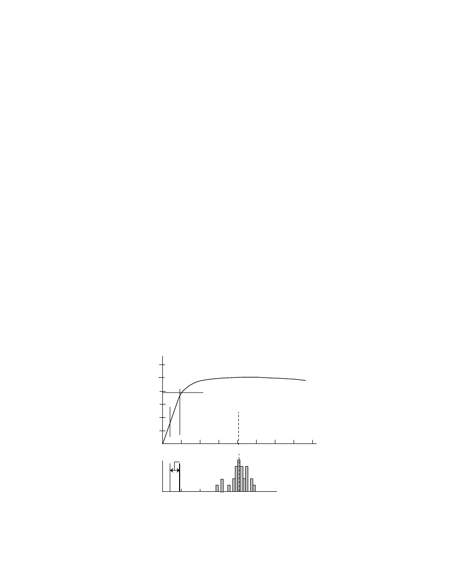
It is not to be expected that the two methods will
produce the same bolt pretension. The calibrated wrench
method has a targeted value of pretension, whereas the
turn-of-nut method simply imposes an elongation on the
bolt. In the former case, bolts of greater than minimum
strength will not deliver pretensions that reflect that
condition, whereas turn-of-nut installations will produce
pretensions that are consistent with the actual strength of
the bolt. Figure 3.4 shows this diagrammatically. Two
bolt lots of differing strength are illustrated. In the turn-
of-nut method, where a given elongation (independent of
bolt strength) is imposed, greater pretensions result for
bolt lot A than for bolt lot B. On the other hand, use of the
calibrated wrench method of installation produces the
same bolt pretension for both lots because the calibration
is targeted to a specific bolt pretension. It therefore does
not reflect the differences in bolt strength.
Laboratory studies show that the actual bolt
pretension obtained when turn-of-nut installation is used
can be substantially greater than the value specified. This
increase is the result of two factors. One is that production
bolts are stronger than the minimum specified value. The
18
other factor is that turn-of-nut installation produces
pretensions greater than the specified value regardless of
the bolt strength. For example, in the case of A325 bolts,
production bolts are about 18% stronger than their
specified minimum tensile strength and turn-of-nut (1/2
turn) produces a pretension that is about 80% of the actual
tensile strength [6]. It follows then that the installed bolt
pretension will be about (
80
.
0
18
.
1
×
=) 0.95 times the
specified minimum tensile strength of A325 bolts. In
other words, the average actual bolt pretension is likely to
exceed the minimum required value by about
(
)
[
]
%
100
70
.
0
/
70
.
0
95
.
0
−
= 35% when turn-of-nut is
used. A similar investigation of A490 bolts installed in
laboratory conditions shows that the average bolt
pretension can be expected to exceed the minimum
required bolt pretension by approximately 26% [6]. Field
studies are available that support the conclusions insofar
as bolts installed by turn-of-nut are concerned [30].
Calibrated wrench installations will produce
pretensions much closer to the target values and they will
be independent of the actual strength of the bolt, as has
been explained previously. Based on laboratory studies,
but using an allowance for a bolt installed in a solid block
(i.e., joint) as compared to the more flexible hydraulic
calibrator, it is shown that the minimum required
pretension is likely to be exceeded by about 13% [6]. The
value 13% was calculated using an assumed target of
7.5% greater than the specified minimum value. If the
calibration is done to the exact value required by the
RCSC Specification, which is a +5% target, then
pretensions can be expected to be about 11% greater than
the specified minimum values. The pretensions in bolts
installed using a calibrated wrench have not been
examined in field joints.
It is shown in Section 5.2 that these observed bolt
tension values are a component of the design rules for
slip-critical connections.
3.2.4 Tension-Control
Bolts
Tension-control bolts, ASTM F1852, are fasteners that
meet the overall requirements of ASTM A325 bolts, but
which have special features that pertain to their
installation [31]. In particular, the bolt has a splined end
that extends beyond the threaded portion of the bolt and
an annular groove between the threaded portion of the
bolt and the splined end. Figure 3.5 shows an example of
a tension-control bolt. The bolt shown has a round head
(also called button or, dome, head), but it can also be
supplied with the same head as heavy hex structural bolts.
The bolt, nut, and washer must be supplied as an
assembly, or, "set."
The special wrench required to install these bolts has
two coaxial chucks—an inner chuck that engages the
splined end and an outer chuck that envelopes the nut.
The two chucks turn opposite to one another to tighten the
bolt. At some point, the torque developed by the friction
Fig. 3.5 Tension-Control Bolt
specified min. pretension
bolt lot B
bolt lot A
bolt elongation
elongation at 1/2 turn-of-nut
turn-of-nut
tension for
bolt lot B
turn-of-nut
tension for
bolt lot A
calibrated wrench
pretension
bolt
pretension
Fig. 3.4 Influence of Tightening Method on Bolt Tension
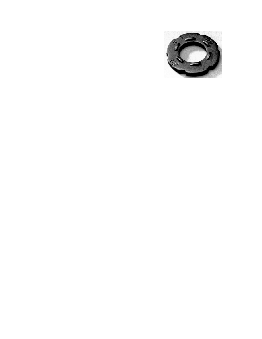
19
between the nut and bolt threads and at the nut–washer
interface overcomes the torsional shear resistance of the
bolt material at the annular groove. The splined end of the
bolt then shears off at the groove. If the system has been
properly manufactured and calibrated, the target bolt
pretension is achieved at this point. Factors that control
the pretension are bolt material strength, thread
conditions, the diameter of the annular groove, and the
surface conditions at the nut–washer interface. The
installation process requires just one person and takes
place from one side of the joint only, which is often an
economic advantage. The wrench used for the installation
is electrically powered, and this can be advantageous in
the field.
Research that investigated the pretension of
production tension-control bolts as it varied from
manufacturer to manufacturer and under different
conditions of aging, weathering, and thread conditions is
available [32]. The results show that the pretension in a
tension control bolt is a strong reflection of the friction
conditions that exist on the bolt threads, on the nut face,
and on the washers supplied with the bolts. In this study,
the quality of the lubricant supplied by the manufacturer
varied, and in many cases the effectiveness of the
lubricant decreased with exposure to humidity and the
elements.
The installation of a tension-control bolt uses a
method that depends on torque. As such, the process
should be subject to the same pre-installation procedure
demanded of calibrated wrench installation. Indeed, this is
the requirement of the RCSC Specification [14]. If
calibration is carried out in accordance with that
Specification, it is reasonable to expect that the bolt
pretensions from tension-control bolts will be similar to
those reported for calibrated wrench installation.
3.2.5 Use of Direct Tension Indicators
Installation of high-strength bolts to target values of bolt
pretension can also be carried out using direct tension
indicators [33]. These are washer-type elements, as
defined in ASTM F959 and shown in Fig. 3.6, that are
placed under the bolt head or under the nut. As the nut is
turned, small arch-shaped protrusions that have been
formed into the washer surface compress in response to
the pretension that develops in the bolt. If a suitable
calibration has been carried out, the amount of pretension
in the bolt can be established by measuring the size of the
gap remaining as the protrusions close. This calibration
requires that a number of individual measurements be
made in a load-indicating device and using a feeler gauge
to measure the gap.
3
For example, there are five
3
In practice, measurements are not performed, but a
verifying feeler gage is used.
protrusions in the direct tension indicating washer used
with a 7/8 in. dia. A325 bolt. There must be at least three
feeler gage refusals at the target value of the gap, which is
0.015 in. Details of the direct tension indicating washer
itself and the procedure necessary for calibration are
given in the RCSC Specification [14] and in the ASTM
Standard [33]. Over and above the particularities of the
direct tension indicating washer itself, the verification
process is similar to that for calibrated wrench
installation.
The use of the load-indicating washer to install high-
strength steel bolts is a deformation method of control,
and so it is not subject to the friction-related variables that
are associated with the calibrated wrench and tension-
control bolt methods. As is the case for the tension-
control bolts, there are not many field studies of the
effectiveness of direct tension indicators. The results that
are available seem to be mixed. In one report [30] the
ratio of measured pretension to specified minimum
tension was 1.12 for a sample of 60 A325 bolts that used
direct tension indicating washers. Although this is not as
high as found in turn-of-nut installations, it is a
satisfactory result. Other studies [34, 35], which
encompassed only A490 bolts, indicate that specified
minimum bolt tensions may not be reached at all when
direct tension indicators are used to install large diameter,
relatively long bolts. Some, but not all, of the difficulties
reported relate to the bolt length and fastener grade, per
se, rather than the use of the direct tension indicator.
However, if the direct tension indicators are used in
accordance with the requirements given in the RCSC
Specification the bolt pretensions that are produced can be
expected to be satisfactory.
3.3 Selection of Snug-Tightened or Pretensioned Bolts
All of the design specifications referenced in this
document (i.e., RCSC, AISC, and AASHTO) require that
the designer identify whether the bolts used must be
pretensioned or need only be snug-tightened. The design
documents must indicate the intention of the designer. In
this way, the plan of the designer when the joint was
proportioned will be fulfilled by those responsible for the
Fig. 3.6 Direct Tension Indicator

20
shop fabrication, field erection, and inspection of the
work.
Bridges—In the great majority of cases, it will be
required that the joints not slip under the action of the
repetitive load that is present in all bridges. In the
terminology of the RCSC Specification, this means that
the joints must be designated as slip-critical. The
AASHTO Specification permits bearing-type connections
only for joints on bracing members and for joints
subjected to axial compression. It is likely that most
bridge documents will require slip-critical joints
throughout in the interest of uniformity.
Buildings—The requirements for buildings allow
more latitude in the selection of bolt installation. It is not
usual for a building to have moving loads, and wind and
earthquake forces are not considered to result in fatigue.
Consequently, the need for pretensioned and slip-critical
bolts is not as frequent in buildings as it is for bridges.
There are three conditions for bolted connections that
can be used in buildings. For economy and proper
function, it is important that the correct one be specified.
• Connections using Snug-Tightened Bolts
Neither the shear strength of a high-strength bolt nor
the bearing capacity of the connected material are
affected by the level of bolt pretension. Likewise, the
tensile capacity is unaffected by bolt pretension,
unless loads that might cause fatigue are present.
(These items are discussed in Chapter 4.) Hence, the
majority of bolted connections in buildings need only
use snug-tightened bolts, i.e., the bolts are installed
using the full effort of an ironworker with a spud
wrench. This is the most economical way of making
bolted connections in buildings because no
compressed air or attendant equipment is needed,
washers may not be required, and inspection is
simple.
• Connections using Pretensioned Bolts
For buildings, only in certain cases is it required that
the bolts be installed so as to attain a specified
minimum pretension. These are enumerated in the
RCSC Specification and they include (a) joints that
are subject to significant load reversal, (b) joints
subject to fatigue, (c) joints that are subject to tensile
fatigue (A325 and F1852 bolts), and (d) joints that
use A490 bolts subject to tension or combined
tension and shear, with or without fatigue. The AISC
LRFD Specification requires pretensioned bolts for
some joints in buildings of considerable height or
unusual configuration, or in which moving machinery
is located.
It is obvious that the bolt installation costs and
inspection for joints requiring pretensioned bolts will
be higher than if the bolts need only be snug-
tightened.
• Slip-Critical Connections
As described earlier, this type of connection is used
mainly in bridges, where fatigue is a consideration.
In buildings, wind is not considered to be a fatigue
phenomena. However, if oversize holes or slotted
holes that run parallel to the direction of the member
forces are used, slip-critical connections are required
in buildings. The RCSC Specification does stipulate
that slip-critical connections be used when "slip at the
faying surfaces would be detrimental to the
performance of the structure." This is generally
interpreted to include the joints in lateral bracing
systems. It is important to note also that connections
that must resist seismic forces need to receive special
attention.
If slip-critical connections are used unnecessarily in
buildings, higher installation and inspection costs will
result.
3.4 Inspection of Installation
3.4.1 General
Inspection of the installation of any fabricated steel
component is important for several reasons. It is self-
evident that the integrity of the component must be
assured by the inspection process. At the same time, the
inspection must be done at a level that is consistent with
the function of the element under examination and an
understanding of its behavior. For example, if the
inspection agency thinks (incorrectly) that bolt
pretensions are subject to a maximum value as well as a
minimum value, this will lead to a dispute with the steel
erector and an unnecessary economic burden. In sum,
then, the level of inspection must be consistent with the
need to examine the suitability of the component to fulfill
its intended function, but it must not be excessive in order
that the economical construction of the job is not affected.
In the case of high-strength bolts, the first step must
be an understanding of the function of the fastener in the
joint. If bolt pretension is not required, then the inspection
process should not include examination for this feature.
This seems self-evident, but experience has proven that
inspection for bolt pretension still goes on in cases where
bolt pretension is, in fact, not required.
The most important features in the inspection of
installation of high-strength bolts are:
• To know whether bolt pretension is required or not.
If bolt pretension is not required, do not inspect for
it.
• To know what pre-installation verification is
required and to monitor it at the job site on a regular
basis.
• To observe the work in progress on a regular basis.

21
Using acoustic methods, it is possible to determine
the pretension in high-strength bolts that have been
installed in the field with reasonable accuracy [29, 30].
However, this process, which determines bolt pretension
by sending an acoustic signal through the bolt, is
uneconomical for all but the most sophisticated
applications. The inspector and the designer must realize
that it is a reality that the bolt pretension itself cannot be
determined during the inspection process for most
building and bridge applications. Therefore, the
importance of the checklist given on the previous page
cannot be overstated.
The AISC LRFD Specification stipulates that
inspection of bolt installation be done in accordance with
the RCSC Specification. The remarks that follow
highlight the inspection requirements: the text specific to
the RCSC requirements should be consulted for further
details.
3.4.2 Joints Using Snug-Tightened Bolts
For those joints where the bolts need only to be brought to
the snug-tight condition, inspection is simple and
straightforward. As described earlier, there is no
verification procedure associated with snug-tightened bolt
installation. The inspector should establish that the bolts,
nuts, washers (if required), and the condition of the faying
surfaces of the parts to be connected meet the RCSC
Specification requirements. Hole types (e.g., oversize,
slotted, normal) shall be in conformance with the contract
documents. The faying surfaces shall be free of loose
scale, dirt, or other foreign material. Burrs extending up to
1/16 in. above the plate surface are permitted. The
inspector should verify that all material within the grip of
the bolts is steel and that the steel parts fit solidly together
after the bolts have been snug-tightened. The contact
between the parts need not be continuous.
These requirements apply equally to A325 and A490
high-strength bolts and to A307 ordinary bolts.
3.4.3 Joints Using Pretensioned Bolts
If the designer has determined that pretensioned bolts are
required, then the inspection process becomes somewhat
more elaborate than that required for snug-tightened bolts.
In addition to the requirements already described for
snug-tightened bolts, the principal feature now is that a
verification process must be employed and that the
inspector observe this pre-installation testing. For any
method selected, this testing consists of the installation of
a representative number of fasteners in a device capable
of indicating bolt pretension. (See Section 3.2.2 for a
description of this process.) The inspector must ensure
that this is carried out at the job site and, in the case of
calibrated wrench installation, it must be done at least
daily. If any conditions change, then the pre-installation
testing must be repeated for the new situation. For
example, if the initial calibration of tension-control bolts
was done for 4 in. long 3/4 in. diameter A325 bolts but 6
in. long 3/4 in. diameter bolts of the same grade must also
be installed on the same day, then a second calibration is
required.
In the case of turn-of-nut pretensioning, routine
observation that the bolting crew applies the proper
rotation is sufficient inspection. Alternatively, match-
marking can be used to monitor the rotation. Likewise, if
calibrated wrench installation has been used, then routine
observation of the field process is sufficient. Because this
method is dependent upon friction conditions, limits on
the time between removal from storage and final
pretensioning of the bolts must be established.
Inspection of the installation of twist-off bolts is also
by routine inspection. Since pretensioning of these bolts is
by application of torque, a time limit between removal of
bolts, nuts and washers and their installation is required,
as was the case with calibrated wrench installation.
Observation that a splined tip has sheared off is not
sufficient evidence in itself that proper pretension exists,
however. This only signifies that a torque sufficient to
shear the tip was present in the installation history. It is
important that twist-off bolts first be able to sustain
twisting without shearing during the snugging operation.
It is therefore important that the inspector observe the pre-
installation of fastener assemblies and assess their ability
to compact the joint without twist-off of tips.
For direct-tension indicator pretensioning, routine
observation can be used to determine that the washer
protrusions are oriented correctly and that the appropriate
feeler gage is accepted in at least half of the spaces
between protrusions. After pretensioning, routine
observation can be used to establish that the appropriate
feeler gage is refused in at least half the openings. As was
the case for twist-off bolts, simply establishing that the
indictor washer gaps have closed can be misleading. The
snug-tightening procedure must not produce closures in
one-half or more of the gaps that are 0.015 in. or less.
3.4.4 Arbitration
The RCSC Specification provides a method of arbitration
for bolts that have been installed and inspected according
to one of the approved methods, but where disagreement
has arisen as to the actual pretension in the installed bolts.
A manual torque wrench is used to establish an arbitration
torque that can then be applied to the bolts in question. As
is pointed out in the Commentary to the RCSC
Specification, such a procedure is subject to all of the
uncertainties of torque-controlled calibrated wrench
installation. In addition, other elements necessary to
control the torque-related issues may be absent. For
example, an installation done originally by turn-of-nut
with no washers will be influenced by this absence of
washers when the arbitration inspection is applied.

22
Passage of time can also significantly affect the reliability
of the arbitration. There is no doubt that the arbitration
procedures are less reliable than a properly implemented
installation and inspection procedure done in the first
place. Those responsible for inspection should resort to
arbitration only with a clear understanding of its inherent
lack of reliability.
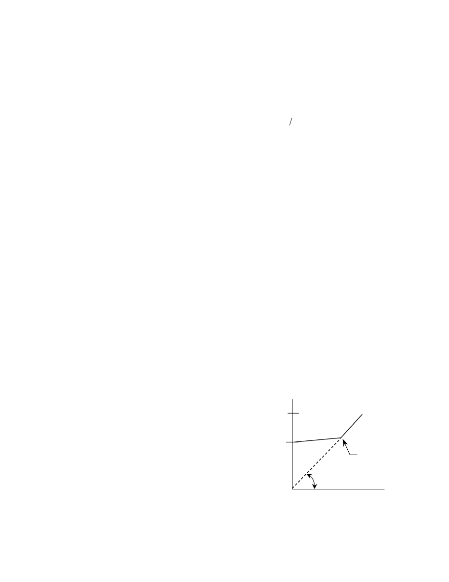
23
Chapter 4
BEHAVIOR of SINGLE BOLTS
4.1 Introduction
The behavior of single bolts in tension, shear, or
combined tension and shear is presented in this chapter.
Features associated with each of these effects that are
particular to the action of a bolt when it is part of a group,
that is, in a connection, are discussed subsequently. Only
the behavior of single bolts under static loading is
discussed in this chapter: fatigue loading of bolted joints
is presented in Chapter 7 and the effect of prying forces is
discussed in Section 6.3.
4.2 Bolts in Tension
The load vs. deformation response of three different bolt
grades was shown in Fig. 1.2. Such tests are carried out
on full-size bolts, that is, they represent the behavior of
the entire bolt, not just a coupon taken from a bolt.
Consequently, the tests display the characteristics of,
principally, the shank and the threaded portion.
Obviously, strains will be largest in the threaded cross-
section and most of the elongation of the bolt comes from
the threaded portion of the bolt between the thread runout
and the first two or three engaged threads of the nut.
The actual tensile strength of production bolts
exceeds the specified minimum value by a fairly large
margin [6]. For A325 bolts in the size range 1/2 in. to 1
in. diameter, the measured tensile strength is about 18%
greater than the specified minimum value, (standard
deviation 4.5%). For larger diameter A325 bolts, the
margin is even greater. For A490 bolts, the actual tensile
strength is about 10% greater than the specified minimum
value (standard deviation 3.5%).
Loading a bolt in tension after it has been installed by
a method that introduces torsion into the bolt during
installation (i.e., by any of the methods described in
Section 3.2) shows that its inherent tensile strength has
not been degraded. The torque that was present during the
installation process is dissipated as load is applied (see
Section 3.2.1). Thus, the full capacity of the bolt in
tension is available. In the case of bolts that were
pretensioned during installation, the only other question
that arises is whether the tension in the pretensioned bolt
increases when a tension load is applied to the connected
parts.
As discussed in Chapter 3, when a bolt is
pretensioned it is placed into tension and the material
within the bolt grip is put into compression. If the
connected parts are subsequently moved apart in the
direction parallel to the axis of the bolt, i.e., the joint is
placed into tension, then the compressive force in the
connected material will decrease and the tensile force in
the bolt will increase. For elastic conditions, it can be
shown [6] that the resulting bolt force is the initial bolt
force (i.e., the pretension) multiplied by the quantity
(
)
[
]
bolt
one
with
associated
area
plate
area
bolt
1
+
. For
the usual bolt and plate combinations, the contributory
plate area is much greater than the bolt area. Thus, the
multiplier term is not much larger than unity. Both theory
and tests [6] show that the increase in bolt pretension up
to the load level at which the connected parts separate is
in the order of only 5 to 10%. This increase is small
enough that it is neglected in practice. Thus, the
assumption is that under service loads that apply tension
to the connected parts a pretensioned bolt will not have
any significant increase in internal load. This topic is
covered more fully in Chapter 6.
Once the connected parts separate, the bolt must
carry the entire imposed external load. This can be easily
shown with a free-body diagram. After separation of the
parts, for example when the ultimate load condition is
considered, the force in the bolt will directly reflect the
external loads, and the resistance will be that of the bolt
acting as a tension link. Figure 4.1 shows diagram-
matically how the internal bolt load increases slightly
until the applied external load causes the connected parts
to separate. After that, the applied external load and the
force in the bolt must be equal.
In principle, the tensile design strength of a single
high-strength bolt should be the product of a cross-
sectional area, the minimum tensile strength of the bolt,
and a resistance factor. The AISC LRFD rule for the
capacity of a bolt in tension directly reflects the
discussion so far. According to Section J3.6 of the
Specification, the design tensile strength (
n
R
φ
) is to be
calculated as—
Bolt
Force
ultimate
initial
Applied Load
separation of
connected
components
Fig. 4.1 Bolt Force vs. Applied Load
for Single Pretensioned Bolt
*
45
°
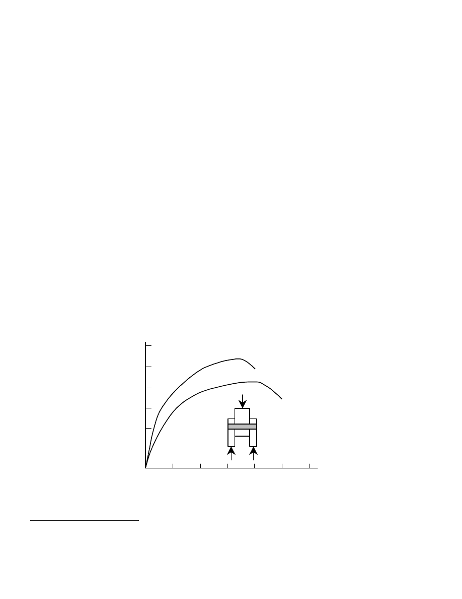
24
b
t
n
A
F
R
φ
=
φ
(4.1)
where
n
R
φ
= design tension strength in tension, kips
φ
= resistance factor, taken as 0.75
t
F
= nominal tensile strength of the bolt, ksi
b
A
= cross-sectional area of the bolt corresponding
to the nominal diameter, in.
2
The nominal tensile strength of a threaded fastener
)
R
(
n
should be the product of the ultimate tensile
strength of the bolt
)
F
(
u
and some cross-sectional area
through the threads. As discussed in Section 1.3, the area
used is a defined area, the tensile stress area (
st
A
), that is
somewhere between the area taken through the thread root
and the area of the bolt corresponding to the nominal
diameter. The expression is given in Eq. 1.1. Rather than
have the designer calculate the area
st
A
, the LRFD
Specification uses an average value of this area for bolts
of the usual structural sizes corresponding to the bolt
diameter—0.75 times the area corresponding to the
nominal bolt diameter.
1
Thus, the nominal tensile strength
st
u
A
F
can be expressed as
)
A
75
.
0
(
F
b
u
. The nominal
tensile strength is written as
b
t
A
F
in Eq. 4.1. Equating
these two expressions, it is seen that
u
t
F
75
.
0
F
=
. Recall
that the ultimate tensile strengths of A325 and A490 bolts
are 120 ksi and 150 ksi, respectively. Application of the
0.75 multiplier to change nominal bolt cross-sectional
area to tensile stress area gives adjusted stresses (
t
F
) of
90 ksi and 113 ksi for A325 and A490 bolts, respectively.
1
The value 0.75 under discussion here is not the value
φ
= 0.75 that appears in Eq. 4.1.
These are the values listed in Table J3.2 of the
Specification. Note that the decreased ultimate tensile
strength of larger diameter A325 bolts (105 ksi) is not
taken into account. It was judged by the writers of the
Specification to be an unnecessary refinement.
The same remarks apply generally to A307 bolts
acting in tension. The nominal strength value given in
Table J3.5 for A307 bolts is 45 ksi, which is the product
u
F
75
.
0
, given that the tensile strength of A307 bolts is
60 ksi.
It was established in Reference [22] that a resistance
factor
85
.
0
=
φ
is appropriate for high-strength bolts in
tension. This is also the value recommended in the Guide
[6]. Thus, the choice of 0.75 for use in Eq. 4.1 is
conservative. To some extent, the choice reflects the fact
that some bending might be present in the bolt, even
though the designer calculates only axial tension.
The strength of a single bolt in tension is a direct
reflection of its ultimate tensile strength. However, there
are several features that can degrade the strength when the
bolt is acting in a connection. These are discussed in
Chapter 6.
4.3 Bolts in Shear
The response of a single bolt in shear is shown in Fig. 4.2
for both A325 and A490 bolts. The type of test illustrated
is done using connecting plates that are loaded in
compression. Similar tests done using connection plates
loaded in tension show slightly lower bolt shear strengths
[6]. (The difference is the result of lap plate prying in the
tension jig tests, which creates a combined state of stress,
deformation (in.)
0.10
0.20
0.30
20
40
60
80
100
120
A490 bolts
A325 bolts
shear
stress
(ksi)
Fig. 4.2 Typical Shear Load vs. Deformation Curves for A325 and A490 Bolts

25
shear plus tension, in the bolt.) It should be noted that
there is little, if any, portion of the response that can be
described as linear. Thus, the best measure of the shear
capacity of a bolt is its ultimate shear strength. The use of
some so-called bolt yield strength is not appropriate.
The tests show that the shear strength of a bolt is
directly related to its ultimate tensile strength, as would be
expected. It is found [6] that the mean value of the ratio of
bolt shear strength to bolt tensile strength is 0.62, standard
deviation 0.03. An obvious question arising from the bolt
shear tests is whether the level of pretension in the bolt
affects the results. Test results are clear on this point: the
level of pretension present initially in the bolt does not
affect the ultimate shear strength of the bolt [6]. This is
because the very small elongations used to introduce the
pretension are released as the bolt undergoes shearing
deformation. Both test results of shear strength for various
levels of initial pretension and bolt tension measurements
taken during the test support the conclusion that bolt
pretensions are essentially zero as the ultimate shear
strength of the bolt is reached. This has implications for
inspection, among other things. If the capacity of a
connection is based on the ultimate shear strength of the
bolts, as it is in a so-called bearing-type connection, then
inspection for pretension is pointless, even for those cases
where the bolts were pretensioned.
The other feature concerning bolt shear strength has
to do with the available shear area. If the bolt threads are
intercepted by one or more shear planes, then less shear
area is available than if the threads are not intercepted.
The experimental evidence as to what the reduction
should be is not clear, however. Tests done in which two
shear planes were present support the idea that the shear
strength of the bolt is a direct reflection of the available
shear area [6]. For example, if one shear plane passed
through the threads and one passed through the shank,
then the best representation was obtained using a total
shear area which is the sum of the thread root area plus
the bolt shank area. These results support the position that
the strength ratio between shear failure through the
threads and shear failure through the shank was about
0.70, i.e., the ratio of thread root area to shank area for
bolts of the usual structural sizes. On the other hand, in
single shear tests this ratio was considerably higher, about
0.83 [36, 37]. Both the RCSC Specification [14] and the
AISC LRFD Specification [17] use the higher value,
slightly rounded down to 0.80. At the present time, the
difference is unresolved.
The AISC LRFD rule for the design strength of a bolt
in shear follows the discussion presented so far. The rule
is given in Article J3.6 of the Specification, as follows:
b
v
n
A
F
R
φ
=
φ
(4.2)
where
n
R
φ
= design shear strength, kips
φ
= resistance factor, taken as 0.75
v
F
= nominal shear strength, ksi
b
A
= cross-sectional area of the bolt corresponding
to the nominal diameter, in.
2
The calculation
of
b
A
should reflect the number of shear
planes present.
As listed in Table J3.2 of the Specification, the
nominal shear strength of the bolt is to be taken as 60 ksi
or 75 ksi for A325 or A490 bolts, respectively, when
threads are excluded from the shear plane. These values
are 0.50 times the bolt ultimate tensile strengths (120 ksi
for A325 bolts and 150 ksi for A490 bolts). If threads are
present in the shear plane, the nominal shear strength is to
be taken as 48 ksi or 60 ksi for A325 or A490 bolts,
respectively. The latter values are 80% of the thread-
excluded case, as explained above.
An explanation is required as to why 0.50 is used
rather than 0.62, which was identified earlier as the proper
relationship. If only one bolt is present, obviously that
bolt carries all the shear load. If two bolts aligned in the
direction of the load are present, each carries one-half of
the total load. However, for all other cases, the bolts do
not carry a proportionate share of the force. As is
explained in Section 5.1, the end bolt in a line of fasteners
whose number is greater than two will be more highly
loaded than fasteners toward the interior of the line. The
effect increases with the number of bolts in the line. The
Specification takes the position that even relatively short
joints should reflect this effect. Accordingly, the
relationship between bolt shear strength and bolt ultimate
tensile strength is discounted by 20% to account for the
joint length effect. The product 0.62
×
80% is 0.50, which
is the value used in the AISC rule for shear capacity. If
the joint is 50 in. or longer, a further 20% reduction is
applied.
The resistance factor used for bolts in shear (Eq. 4.2)
is
75
.
0
=
φ
. Until the effect of joint length upon bolt
shear strength is presented (Section 5.1), the selection of
0.75 cannot be fully discussed. However, it can be noted
that the resistance factor recommended by the Guide [6],
which is based on the study reported in Reference [22], is
0.80.
4.4 Bolts in Combined Tension and Shear
Figure 1.5 showed how bolts can be loaded in such a way
that both shear and tension are present in the bolt.
Chesson et al. [38] carried out a series of tests on bolts in
this condition, and these test results form the basis for the
AISC LRFD rules. Two grades of fastener were tested:
A325 bolts and A354 grade BD bolts. The latter have
mechanical properties equivalent to A490 bolts. The test
program showed that the only variable other than bolt
grade that affected the results was bolt length. This was
expected: as bolt length increases bending takes place and
the bolt shear strength increases slightly. (This is the

26
consequence of the fact that the shear planes through a
curved bolt are slightly larger than if the bolt were
straight.)
An elliptical interaction curve was fitted to the test
results. The expression given in the Guide [6], which is
applicable to both A325 and A490 bolts, is:
(
)
0
.
1
y
62
.
0
x
2
2
2
=
+
(4.3)
where
=
x
ratio of calculated shear stress )
(
τ to bolt
tensile strength
)
(
σ
y = ratio of calculated tensile stress )
(
σ to bolt
tensile strength
)
(
σ
The shear stress is calculated on the applicable area,
the shank or through the threads, and the tensile stress is
calculated on the tensile stress area. The researchers [38]
also suggested a three-straight line approximation to the
results, and this is the model used in the LRFD rules.
The requirements for bolts in combined shear and
tension are in AISC LRFD Article J3.7 and Table J3.5.
The LRFD rules use a three straight-line approximation of
the ellipse that is fitted to the test results (Eq. 4.3),
adjusted to match the permissible tensile strength and
shear strength limits established by LRFD for each of
these conditions acting singly. The rules present a straight
line cutoff at the maximum permissible tensile stress, a
straight line cutoff at the maximum permissible shear
stress, and a sloping straight line in-between.
For A325 bolts when the shear plane will pass
through the shank only, the interaction equation is:
90
f
0
.
2
117
F
v
t
≤
−
=
(4.4)
and for A325 bolts when the shear plane will pass through
the threads:
90
f
5
.
2
117
F
v
t
≤
−
=
(4.5)
For A490 bolts and no threads in the shear plane:
113
f
0
.
2
147
F
v
t
≤
−
=
(4.6)
and for A490 bolts in which there are threads in the shear
plane:
113
f
5
.
2
147
F
v
t
≤
−
=
(4.7)
Equations 4.4 through 4.7 use the AISC LRFD
notation for stresses. The resistance factor
75
.
0
=
φ
must
be applied to the result obtained by these equations. When
the design tension strength of the bolt (now reduced by
the presence of shear) is determined using Equation 4.1,
the resistance factor appears in that equation.
In applying these rules, it is apparent that the tensile
stress is limited to the nominal tensile strength of the bolt,
90 ksi for A325 and 113 ksi for A490. It should be
remembered, as well, that there is also a limit on the
calculated shear stress,
v
f
(computed under the factored
loads). It must be equal to or less than the nominal shear
strength multiplied by the resistance factor.
An advantage of the straight-line representation is
that it identifies the range of shear stress values for which
a reduction in tensile strength needs to be made. For
example, a reduction in tensile strength for A325 bolts (no
threads in shear plane) is required when the calculated
shear stress under the factored loads is between 13.5 ksi
and the maximum permitted value of 45 ksi (i.e., 60 ksi
× φ ). At the former, the nominal tensile stress is, of
course, 90 ksi, and at the latter it has been reduced to 27
ksi.
The elliptical representation and the straight-line
representation fit the test data about equally well when the
forms presented in Reference [26] are applied. In the
formulation used by AISC (Equations 4.4 through 4.7),
the result will be conservative. It has already been
pointed out in this Chapter that the AISC LRFD rules for
the tension-only and the shear-only cases are themselves
conservative.
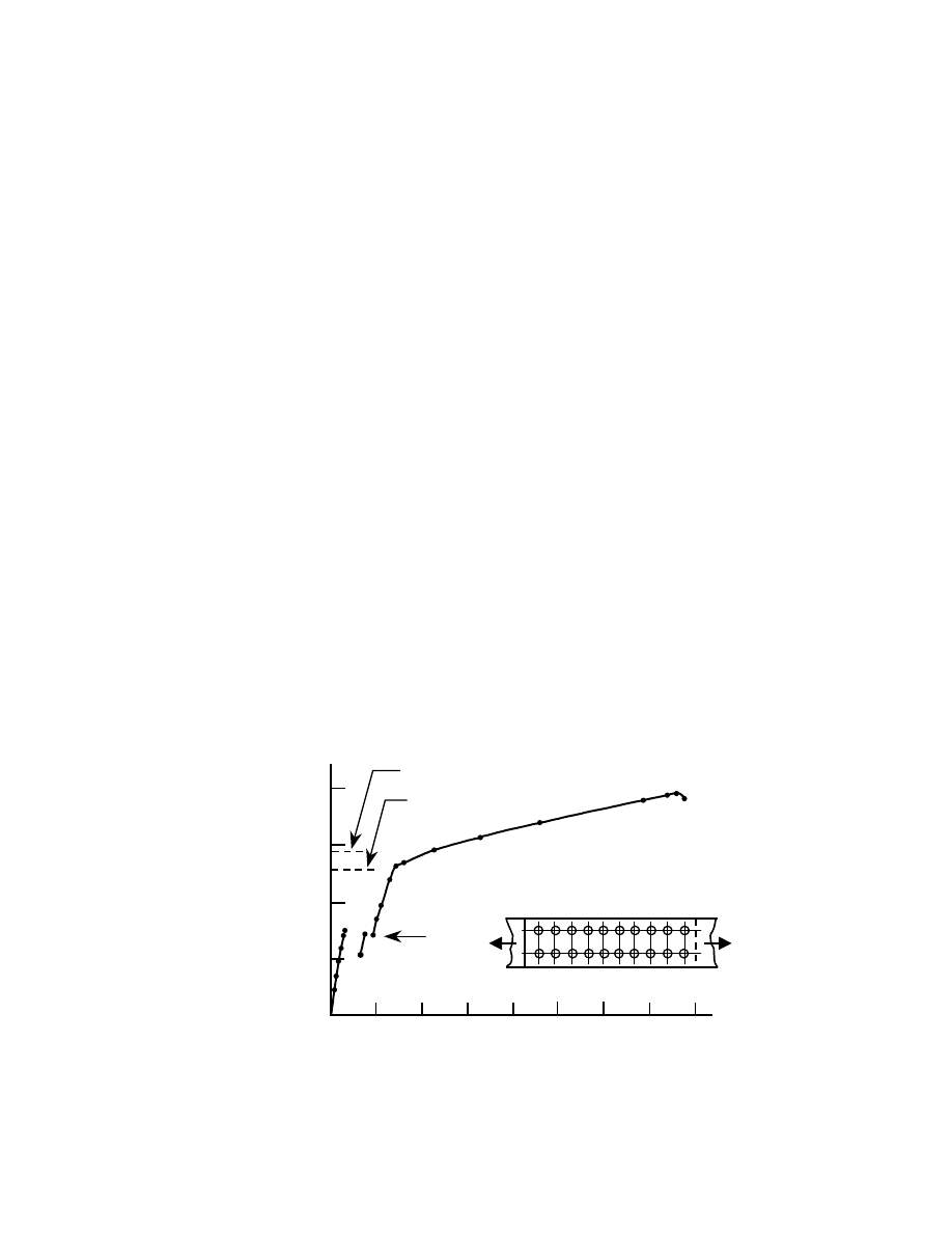
27
Chapter 5
BOLTS IN SHEAR SPLICES
5.1 Introduction
Figure 1.3 (a) showed a symmetric butt splice that uses
plates to transfer the force from one side of the joint, say,
the left-hand main plate, to the other, the right-hand main
plate. (Most often, the main plate shown in this pictorial
will actually be a structural shape like a W–shape, but the
behavior can be more easily described using a plate.)
Such a connection is used, for instance, to splice the chord
of a truss.
The behavior of a large splice that was tested in the
laboratory is shown in Fig. 5.1 [6]. This joint used ten 7/8
in. dia. A325 bolts in each of two lines. The holes were
sub-drilled and then reamed to 15/16 in. dia., that is, they
were 1/16 in. dia. larger than the bolts. The bolts were
pretensioned using the turn-of-nut method. The plates
were ASTM A440 steel and the measured strengths were
42.9 ksi static yield strength and 76.0 ksi ultimate. The
slip coefficient of this joint was measured as 0.31.
The load vs. deformation response is reasonably
linear until the joint slips. Following slip, which means
that the plates are pulled up against the sides of at least
some of the bolts, the joint at first continues to load at
more or less the same slope as the initial region. Yielding
of the connected material starts to occur, however, first in
the net cross-section and then throughout the connected
material. The ultimate load that this joint could carry
corresponded to an average bolt shear stress of 67.0 ksi.
However, tests of single bolts taken from the same
manufacturing lot showed that the shear stress at failure
was 76.9 ksi.
The behavior of this joint, which is reasonably
representative of splices of this type, raises the following
points:
• How much slip is likely to take place?
• Why is the average bolt shear stress at failure of
the multi-bolt joint less than the bolt shear stress
when a single bolt is tested?
If the bolts had not been pretensioned, the connected
material would have been expected to pull up against the
sides of the bolts at a relatively low load. In the case of
the joint depicted in Fig. 5.1, this slip did not occur until
the frictional resistance had been overcome, of course. In
the most unfavorable condition, the amount of slip can be
two hole clearances, i.e., 1/8 in. in this case. Since the
bolts and their holes cannot all be expected to be in their
"worst" locations, the amount of slip that actually takes
place is observed to be much less than two hole
clearances. In laboratory specimens, the amount of slip in
such joints is about one-half a hole clearance [6], and
values measured in the field are even less [39]. Thus,
unless oversize or slotted holes are used, it can be
expected that if joint slips occur they will be relatively
small.
The reason that the average ultimate bolt shear stress
in a multi-bolt joint is less than that of a single bolt can be
explained qualitatively with the aid of Fig. 5.2. In plate A
(the main plate) 100% of the load is present in the plate
until the bolts start to transfer some load into the lap
plates (plates B in the figure). Consider a high load, say,
near ultimate. In plate A between bolt lines 1 and 2 the
stress in the plate will still be high because only a small
0.20
0.40
0.60
0.80
1600
Load
kips
Joint Elongation, in
.
slip
yield on gross cross-section
yield on net cross-section
1200
800
400
Fig. 5.1 Load vs. Elongation Behavior of a Large Joint
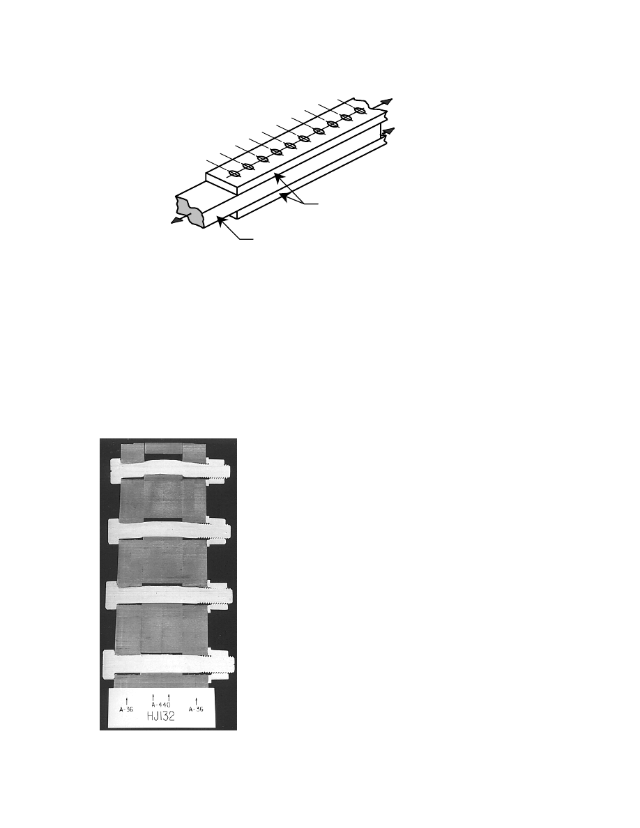
28
amount of load has been removed (by bolt 1). Strains in
this plate are correspondingly high. Conversely, the stress
in the lap plates B between lines 1 and 2 is low because
only a small amount of force has been taken out of the
main plate and delivered to the lap plates. Thus, strains in
the lap plates between bolt lines 1 and 2 will be low. This
means that the differential in strain between plates A and
B will be large in the region near the end of the joint.
Consider now the region near the middle of the joint,
say, between bolt lines 5 and 6. Whatever the distribution
of shear forces in the bolts, a considerable amount of the
total joint force has now been taken out of plate A and put
into plates B. Thus, the strains in the former have
decreased as compared to the condition near the end of
the joint and the strains in the latter have increased.
Consequently, the differential in strains between the two
plate systems is less near the middle than it was near the
end. Since the bolt shear force is the result of the
imposition of these relative strains [6], bolts near the end
of a joint will be more highly loaded than those toward
the middle. It is worth noting that this uneven loading of
the bolts in shear is accentuated as the joint load is
increased from zero. It used to be argued that, even
though the bolt shear force distribution was uneven at
working loads, it would equalize as the ultimate load
condition was reached. In fact, the converse is true.
The uneven distribution of forces in a multi-bolt
shear splice can be seen in Fig. 5.3. Shown in this sawn
section are the end four bolts in a line of 13. The top bolt
(the end bolt) is close to failure, whereas the fourth bolt
from the top has significantly less shear deformation and,
hence, shear force.
The designer must decide first whether a slip-critical
connection is needed or not. If it is, then the appropriate
design rules must be identified. If a bearing-type joint is
satisfactory, then those design rules must be followed.
(Bearing-type design implies both bolt shear strength and
the bearing capacity of the connected material, as
explained in Section 1.4) Because slip-critical joints are
designed at the service load level, it is also a requirement
that the ultimate strength criteria, i.e., the bearing-type
joint rules, be met at the factored load level. The
remaining sections in this Chapter will discuss these
issues.
5.2 Slip-Critical Joints
Section 3.3 discussed the cases where slip-critical
connections are needed. If proper functioning of the
structure requires that a joint not slip into bearing, then
this requirement is described as a serviceability limit
state. In building design according to the AISC LRFD
specification, the requirement is that the joint not slip
under the action of the service loads. It will be seen that
the AISC LRFD specification also provides a rule for
design of a slip-critical joint under the factored loads.
A
P
P/2
1
2
3
4
5
6
7
8
10
9
P/2
B
Fig. 5.2 Load Partition in Multi-Bolt Joint
Fig. 5.3 Sawn Section of a Joint

29
This is primarily a matter of convenience: it is intended
that the result be the same, more or less, whichever the
starting point. In the case of the AASHTO specification
for the design of bridges, prevention of slip is required
under a force that includes the service load multiplied by
1.30.
From first principles, the slip resistance of a bolted
joint can be expressed as:
∑
=
i
s
T
n
k
P
(5.1)
where
s
k
= slip coefficient of the steel
n = number of slip planes (n is usually either one or
two)
i
T
= bolt pretension (in each individual bolt)
Neither the slip coefficient nor the bolt tension forces
are deterministic. They are reasonably represented as log-
normally distributed and can therefore be characterized by
a mean value and its standard deviation. Given this type
of information, which is available from laboratory studies
on full-size joints, it is possible to determine a probability
of slip for given starting conditions [6]. The result reflects
two important realities, described following.
As-delivered bolts have a tensile strength that is
greater than the specified minimum tensile strength. For
A325 bolts, this increase is about 20% and for A490 bolts
it is about 7% [22].
The pretension in installed bolts will be greater than
the specified minimum pretension, which is 70% of the
bolt specified ultimate tensile strength. Generally, the
pretension in bolts installed by turn-of-nut will be greater
than that for bolts installed by calibrated wrench.
In order to provide a design equation, a probability of
slip must be selected. Based on past experience, this was
taken by the Guide [6] to be about 5% when turn-of-nut
installations are used and about 10% when calibrated
wrench is used. (The examination at the time did not
include twist-off bolts or bolts that use load-indicating
washers.) In the RCSC Specification [14], this design
equation is written as:
s
b
m
s
N
N
T
D
R
µ
φ
=
(5.2)
where
s
R
= slip resistance of the joint
=
b
N
number of bolts
=
s
N
number of slip planes
=
µ
slip coefficient (
≡
s
k
in Eq. 5.1)
=
m
T
specified minimum bolt pretension
,
80
.
0
D
=
a slip probability factor that reflects the
distribution of actual slip coefficients about their
mean value, the ratio of measured bolt tensile
strength to the specified minimum values, and
the slip probability level (e.g., 5% in the case of
turn-of-nut installation.
=
φ
modifier to reflect the hole condition (standard,
oversize, short-slotted, long-slotted in direction
of force, or long-slotted perpendicular to force).
Note that the term
φ
in this equation is not the
resistance factor usually associated with LRFD.
It can be seen that Eq. 5.2 is basically the same as
Eq. 1, which expressed the slip load in fundamental terms.
The modifier
φ
is used to reflect the decrease in bolt
pretension that is present when oversize or slotted holes
are used. The term D embodies the slip probability factor
selected and provides the transition between mean and
nominal bolt tension and slip values. In the form given by
Eq. 5.2, the Guide can be used to obtain slip loads for
other failure probabilities and various other conditions
when necessary.
The AISC LRFD rules for design of slip-critical
connections are presented in both factored load terms
(Article J3.8a) and in service load terms (Article J3.8b).
The LRFD expresses the slip load resistance per bolt
when factored loads are used as (Article J3.8a) —
s
m
str
N
T
1.13
R
µ
φ
=
φ
In this form, the resistance equation is closely
identified with Eq. 5.2, i.e., it expresses the resistance in
terms of the fundamentals of the problem—clamping
force (
m
T
), slip coefficient (
µ
), and the number of slip
planes (
s
N
). The
φ
–value, described in the specification
as a resistance factor, is really the adjustment required for
hole configuration, as discussed above.
1
The modifier
1.13 reflects the observed increase in bolt clamping force
(above the specified minimum bolt tension,
m
T
) when
the calibrated wrench method of installation is used [6].
An advantage of the factored load design is that cases
other than clean mill scale can be accommodated. Most
importantly, the expression reflects the principles
involved.
The requirements for slip-critical design when the
service loads are used as the starting point (Article J3.8b)
are actually in Appendix J3.8b. In the service load
presentation, the result is given in the form of permissible
bolt shear stress. Unfortunately, this obscures the
fundamentals of the design problem, i.e., the relationship
of the slip load to the surface condition of the faying
1
In the LRFD Specification, the modifier
φ
is taken as
unity for standard, oversized, short-slotted, and long-
slotted holes when the long slot is perpendicular to the
line of the force. For long-slotted holes when the long slot
is parallel to the line of the force,
85
.
0
=
φ
. Further
information on the effect of oversize or slotted holes can
be found in Section 8.3 .

30
surfaces and to the clamping force provided by the bolts
(Eq. 5.1 or 5.2). In a slip-critical connection the bolts do
not act in shear. It is not until the slip resistance has been
overcome that shear forces act on the bolts.
Appendix J3.8b says that the design resistance to
shear per bolt is
b
v
A
F
φ
. The modifier
φ
has already
been described above for load factor design. The cross-
sectional area of the bolt is expressed as
b
A
. The
permissible shear stress, given in Table A–J3.2, is for so-
called Class A surfaces with slip coefficient
33
.
0
=
µ
.
(The designer is permitted to adjust the tabulated values if
it is necessary to use another slip coefficient.)
The pseudo shear stress given in Table A–J3.2 can be
derived by first expressing the resistance (force) of a
single bolt in slip-critical joint in terms of this shear stress
as—
s
b
b
N
A
τ
where
=
τ
b
equivalent shear stress (i.e., the value tabulated
in LRFD Table A–J3.2)
=
b
A
cross-sectional area of one bolt
Equate this to the resistance given by Eq. 5.2 and use
the particular case of one bolt (
b
N
=1) and standard size
hole size (
0
.
1
=
φ
):
s
b
b
N
A
τ
=
s
m
N
T
D
µ
Solving for the shear stress
b
m
b
A
T
D
µ
=
τ
but,
u
st
m
A
70
.
0
T
σ
=
(see Section 3.2.1)
where
st
A
is the tensile stress area of the bolt and
u
σ
is
the bolt ultimate tensile strength. Making this
substitution—
b
u
st
A
A
0.70
D
σ
µ
=
τ
For bolts of the usual structural size, the ratio
b
st
A
A
is about 0.76. A value for the slip probability
factor, D, has to be obtained from the Guide [6]. For the
particular case of A325 bolts (
ksi
120
u
=
σ
) and clean
mill scale steel
)
33
.
0
(
=
µ
, the value of D is 0.820.
Making the substitutions, an equivalent shear stress of
17.3 ksi is calculated. In the AISC LRFD specification,
Table A–J3.2 gives a shear stress of 17 ksi for this case.
Other cases can be derived in a similar fashion.
Whether the slip-critical connection has been
designed at the service load level or at the factored load
equivalent, as just described, it is necessary that the joint
still be checked under the factored loads. This means
evaluation of the shear strength of the fasteners and the
bearing capacity of the connected material. These topics
are discussed in the next section.
5.3 Bearing-Type Joints
5.3.1 Introduction
If it is not required that a joint be slip-critical, then the
design issues are the shear capacity of the bolts and the
bearing capacity of the connected material. These were
the features contemplated in the discussion presented in
Section 1.4. There has already been some discussion
about the shear capacity of a single bolt (Section 4.3) and
the effect of joint length upon bolt shear strength (Section
5.1). In Section 5.3, the bolt shear capacity discussion will
be completed and the subject of bearing capacity in the
connected material will be presented.
5.3.2 Bolt Shear Capacity
The AISC LRFD rule for the capacity of a bolt in shear
was presented in Section 4.3. In brief, Article J3.6 of the
Specification stipulates that:
b
v
r
A
F
V
φ
=
(4.2)
where
=
r
V
factored shear resistance
φ
= resistance factor, taken as 0.75
=
v
F
nominal shear strength of the bolt
b
A
= cross-sectional area of the bolt,
2
.
in
In Section 4.3, it was noted that the nominal shear
strength of the bolt is to be taken as 0.50 times the bolt
ultimate tensile strength (i.e., 120 ksi for A325 bolts and
150 ksi for A490 bolts), adjusted as necessary if threads
are present in the shear plane.
The Specification takes the position that even
relatively short joints should reflect the effect of joint
length upon bolt shear strength. (The joint length effect
was explained in Section 5.1.) Accordingly, the
relationship between bolt shear strength and bolt ultimate
tensile strength, which has been determined from tests to
be 0.62, is immediately discounted by 20% to account for
the joint length effect. Thus, the multiplier applied to bolt
ultimate tensile strength in order to obtain the bolt shear
strength is 0.62
×
80% = 0.50. This is the value used to
obtain the bolt nominal shear strength values given in
Table J3.2 of the Specification. If the joint length exceeds
50 in., a further 20% reduction must be applied to Eq. 4.2.
The use of the 0.50 multiplier (rather than the value
of 0.62) for the relationship between shear strength and
bolt ultimate tensile strength and the use of 0.75 as the
resistance factor create a conservative position for the
AISC LRFD rules. In the Guide, it is established that no
reduction in bolt shear strength with respect to joint
length is required until joint length is about 50 in. In
allowable stress terms, the factor of safety in joints up to
that length is at least 2.0 for both A325 bolts and A490
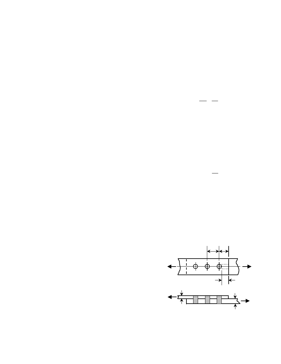
31
bolts in higher strength steels (which is the conservative
choice in the model). Thus, use of the 0.62 multiplier
means that shorter joints will simply have a larger margin
of safety. Since the 2.0 value was adequate (by
experience) for long joints, no reduction is really
necessary up to that joint length. The same comments
generally apply in load factor design, given a load factor
of about 1.6.
The selection of 0.75 as the resistance factor in the
AISC rules is likewise conservative. The value of 0.80 is
more appropriate, as developed in Reference [22].
Finally, a comment needs to be made regarding the
application of the joint length effect to the type of
connection in which load is transferred from a beam or
girder web to another member, for example, a column.
The length effect reduction is derived from the shear
splice model. To what extent it applies to the web framing
angles case is uncertain, but it is reasonable to think that
the same phenomenon at least does not take place to the
same degree. Indeed, one international specification [40]
specifically excludes the joint length effect for the design
of bolts in framing angle connections.
5.3.3 Bearing Capacity
The fashion in which the connected material reacts
against a bolt that is loaded in shear was described in
Article 1.4. Figure 1.6 (d) showed pictorially the bearing
force acting against the connected material, and the actual
effect of the contact between bolts and connected material
can be seen in Fig. 5.3. The discussion in this section will
deal with how the member (connected material) can reach
its limit state in bearing and will also introduce the AISC
LRFD Specification design rules.
Figure 1.6 showed the action of a single bolt. If this
bolt is close to the end of the connected part (see Fig. 1.6
(d)), then obviously one possible limit state is that a block
of material will shear out between the bolt and the end of
the end of the connected part. The other possibility is that
excessive deformations occur as the connected material
yields. Often, a combination of these two features is
observed in tests.
A rational model that describes the shearing behavior
can be developed, and this is done in the Guide [6]. The
model gives good agreement with test results, but a
simpler model is also available that is sufficiently
accurate. This uses a shear-out of a block of material
between the end bolt and the adjacent connected material,
shown as a dotted box in Fig. 5.4. This strength is
(
)
t
L
2
c
u
×
×
τ
. The relationship used to describe the
ultimate shear strength is
u
u
75
.
0
σ
=
τ
. The multiplier
0.75, which might appear to be conservative, reflects the
strain hardening that is observed and the fact that the
shear surfaces are really longer than assumed. Thus, the
shear resistance of this bolt is given by
t
L
5
.
1
R
c
u
n
σ
=
(5.3)
In accordance with the concepts shown in Fig. 1.6, t
must be the thinner of two connected parts. See also
Fig. 5.4. If three (or more) plies are connected, t is the
thinner of
2
3
1
t
or
t
t
+
.
The relationship given by Eq. 5.3 becomes less valid
when the end bolt is relatively far from the end of the
connected material. This is because the failure mode
changes from shearing out of material to excessive
yielding. Based on the test results [6], the relationship
between bearing stress and plate ultimate strength can be
described as
d
L
e
pl
u
b
=
σ
σ
where
e
L
is shown in Fig. 5.4, d is the bolt diameter, and
the other two terms are
=
σ
b
bearing capacity of the connected material
=
σ
pl
u
ultimate tensile strength of the connected
material.
It is assumed that the bearing stress acts on a
rectangular area
t
d
×
. Solving the expression given above
for the bearing stress and multiplying by this area gives a
permissible load based on bearing capacity as
t
d
d
L
R
e
pl
u
n
σ
=
From the tests, it is observed that this capacity controls
for values of
d
3
L
e
≥
. Making this substitution and
using the LRFD notation
pl
u
u
F
σ
≡
gives
u
n
F
t
d
3
R
=
This is written as a limit to Eq. 5.3, and the final
expression given as LRFD J3–2c is written as
u
c
u
n
F
t
d
0
.
3
t
L
5
.
1
R
≤
σ
=
(5.4)
Of course, Eq. 5.4 must still be multiplied by a
Fig. 5.4 Bearing Nomenclature
t
1
t
2
…
L
e
s
L
c
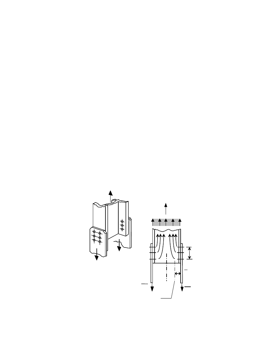
32
resistance factor,
φ , to obtain the design bearing strength.
The value
75
.
0
=
φ
is used.
The case under discussion has been for a bolt in a
standard hole, oversized hole, short-slotted hole, or long-
slotted hole parallel to the direction of load, and for the
circumstance where bolt hole deformation at service load
is not a design consideration. A separate expression
(LRFD J3–2c) is given for the same circumstances except
that the long-slotted hole is oriented perpendicular to the
direction of the force.
When bolt hole deformation is a consideration, the
capacity is reduced and given as
u
c
u
n
F
t
d
4
.
2
t
L
2
.
1
R
≤
σ
=
(5.5)
The user of the LRFD Specification is not given
much help in deciding when deformation around holes
should be a design consideration. Therefore it is
instructive to look at the basis of Eq. 5.5.
Equation 5.5 was developed from tests reported in
Reference [41]. Equation 5.5 is a limit based on
deformation, and it was selected as the point at which
0.25 in. of joint deformation had been reached. According
to these researchers, at about this deformation most of the
ultimate strength had been reached in the tests and a
considerable extension beyond this point is required to
attain the full strength capacity. The test specimens were
configured so that the critical element was the lap plates
in a butt splice. In these tests, the lap plates could deform
out-of-plane since they are unconfined by the assembly. A
central conclusion in [41] is that tests in which the
unconfined plates fail as compared to tests in which the
confined plates fail present significantly different
conditions of bearing stress failure. Other noteworthy
conditions in these tests were that the lap plates were very
thin (1/4 in.) and the plates were sometimes very wide (up
to 8 in.). An 8 in. wide plate containing a single line of
bolts, as was the case in some of these tests, exceeds the
maximum permissible edge distance permitted in the
Specification. A further feature of some of the test
specimens was large end distances, up to 9 in. This also
would not be permitted under the limits in the
Specification. Whatever limitations that might be present
as a result of the geometrical features of these tests, the
best measure is how these results compare to those done
when the confined plates fail in bearing. This comparison
is made in the Guide [6], where it is clear that the
unconfined test results fall easily within the normal scatter
of the total results. The only remaining question then is
whether it is necessary to limit the deformation of any of
the individual tests because ultimate bearing capacity only
is attainable at large deformations.
It is the author's opinion that the majority of
structural connections will not display the type of
behavior demonstrated in these tests: component sizes in
fabricated steel construction will be more robust than
those reported in [41]. Furthermore, the concept of
limiting deflections is arguable, as long as these
deflections are within reason. The limit used, 0.25 in.,
could be increased to, say 3/8 in., without endangering the
structure. It must be remembered that these deflections
P
2
P
P
2
L
σ
(a)
centroid of area tributary
to gusset plate
(b)
Fig. 5.5 Shear Lag in Gusset Plate Connection
x
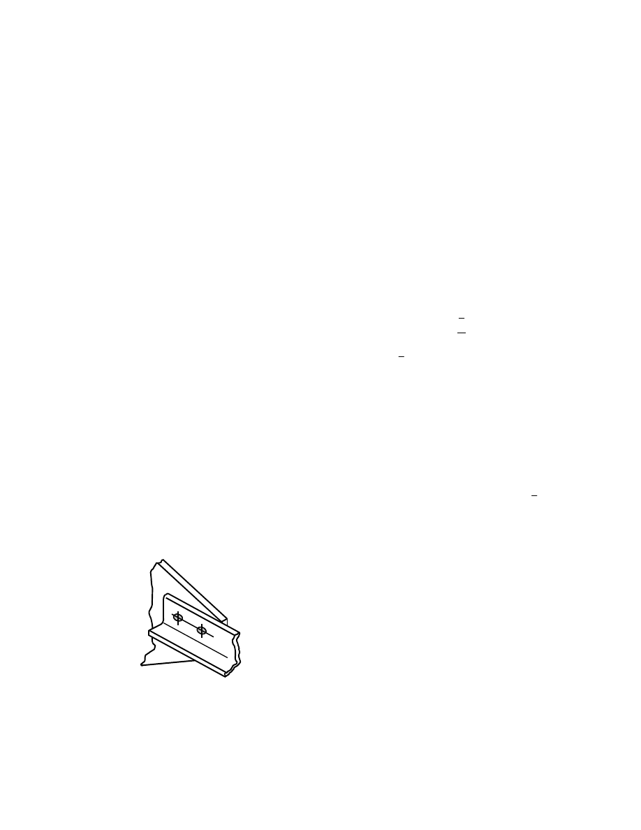
33
are present only as the structure approaches its ultimate
capacity. Second-order effects, even in multi-story
buildings, will not be significant with slips of this
magnitude.
The resistance factor to be applied to the bearing
capacity equations given in the LRFD Specification is
0.75. This is one of the few locations where the
Specification choice seems to be non-conservative as
compared with published material. In Reference [22], the
value is calculated to be 0.64.
5.4 Shear Lag
For truss members, it is usual to transfer the force into or
out of the member by means of gusset plates, as shown in
Fig. 5.5. Generally, it is impractical to try to connect all of
the cross-section of the shape. For instance, as illustrated
in Fig. 5.5(a), the flanges of the W–shape are attached to
the gusset plates, but the web is not directly connected.
Consequently, the flow of stress from the bolts into the
W–shape must be something like that shown in Fig.
5.5(b). Intuitively, it is to be expected that a long
connection will be more favorable for this stress flow.
Likewise, if the shape is shallow, the stress flow will be
more favorable than if it is deep. The effects of these
features of the geometry have been demonstrated in
physical testing.
Another example is shown in Fig. 5.6, where a single
angle is connected to a gusset plate. In this case, the
outstanding leg of the angle is not connected. Again, an
uneven distribution of stresses from the fasteners into or
out of the angle is expected and the outstanding leg of the
angle may not be fully effective. What this means, in both
the illustrations used, is that the full cross-sectional area
of the shape may have to be discounted (in addition to the
fact that holes are present) in order to be able to predict
the capacity of the member. This phenomenon is referred
to as shear lag.
The most obvious geometrical features that
determines the severity of the shear lag are (a) the
displacement of the centroids of the gusset plates relative
to the member and (b) the length of the connection. (If the
joint is particularly long, then that itself can also have an
effect, as was explained in Section 5.1.) Physical testing
has shown that other features such as the ductility of the
material being joined, the method of making the holes
(e.g., punched or drilled), the proximity of one hole to
another, and so on, generally have a small influence.
Although a number of investigations have been
performed to study the shear lag effect, the current North
American design standards are based mostly on the work
of Munse and Chesson [42, 43] This work included
examination of different cross-sectional configurations,
connections, materials, and fabrication methods. An
empirical equation to calculate the net section efficiency
was proposed. It was based on the test results of 218
specimens. This equation was verified further by a
comparison with more than 1000 other test data. Using
the assumption that the net area will be calculated using
the so-called
g
4
/
s
2
rule and that the hole diameter will
be taken as 1/16 in. greater than the actual hole size [20],
then according to Munse and Chesson the predicted net
section load of a tension member is given by
u
n
u
F
A
L
x
1
P
−
=
(5.6)
in which
L
and
x
are terms that describe the geometry
(Fig. 5.5),
n
A
is the net cross-sectional area, and
u
F
is
the ultimate tensile strength of the material.
Direct use of Eq. 5.6 presents a problem for the
designer because the length of the connection, L, must be
known (or assumed) before it can be applied. Thus, an
iterative solution is indicated.
The expression for the capacity of a tension member
in the AISC LRFD Specification [17] is a direct reflection
of Eq. 5.6. See Article B3 of the Specification. An upper
limit of 0.9 is given for the term
L
/
x
1
−
, which is
designated as U in the Specification. Again the difficulty
mentioned above arises, that is, the calculation process
must be iterative because the length of the connection is
not known in advance of the design of the tension
member. However, in the Commentary to the LRFD
Specification, certain approximations for U are permitted.
They are based on the examination of a large number of
hypothetical cases, and are as follows.
(a) W, M, or S shapes with flange width not less
than 2/3 the depth (and structural tees cut from
these shapes), provided the connection is to the
flanges and there are at least 3 fasteners per line
of bolts: use U = 0.90.
(b) W, M, or S shapes (or structural tees) not
meeting the requirements of (a) and all other
shapes, provided the connection is to the flanges
and there are at least 3 fasteners per line of bolts:
use U = 0.85.
(c) All members having only two fasteners per line:
use U = 0.75.
Fig. 5.6 Shear Lag in Angle Connection

34
These approximations seem to give satisfactory
results for the cases involving W, M, or S shapes, and it is
always easy to check the result using Eq. 5.6 once the
details have been established. However, there is recent
work that indicates that neither Eq. 5.6 or the use of the
U–value approximations are satisfactory for angles that
are connected by one leg [44]. For a large group of test
specimens, taken from several different sources, it was
found that Eq. 5.6 overestimated the ultimate load by a
factor of 1.19, standard deviation 0.13 [44]. These
researchers provide the following predictor equation for
the strength of angles (either single or arranged as a
pair)—
o
y
cn
u
u
A
F
A
F
P
β
+
=
(5.7)
where
=
u
P
ultimate load
=
u
F
ultimate tensile strength of the material
=
y
F
yield strength of the material
=
cn
A
net area of the connected leg (taking holes
as 1/16 in. greater than the nominal hole size
and using the
g
4
/
s
2
rule if necessary)
=
0
A
area of the outstanding leg (gross area)
=
β
1.0 for connections where there are 4 or more
fasteners per line or 0.5 for connections where
there are 3 or 2 fasteners per line
Application of Eq. 5.7 to the test results gave a ratio
of predicted load to test load of 0.96, standard deviation
0.08. Use of this equation again requires that the length of
the connection (i.e., number of bolts per line in the
direction of the member force) be known. Consequently,
an examination was made of a large number of cases
(about 1500) in an effort to provide an equation that could
be used directly for design [44]. The result is a modifier to
the net section, calculated in the usual way, that takes the
same form as the AISC modifier U. This is—
n
e
A
U
A
=
(5.8)
where
=
e
A
effective net area, to be used in calculating
the ultimate load
=
n
A
net area calculated in the usual way
U = 0.80 if the connection has 4 or more fasteners
in line or 0.60 if there are 3 or 2 fasteners per
line.
Using Eq. 5.8 gave prediction results nearly as good
as those obtained using Eq. 5.7.
Users of the AASHTO [19] and AREA [45]
specifications should be aware that the design rules for
the capacity of angles connected by only one leg are
somewhat different than those of AISC. The work in
Reference [44] showed that the current AASHTO and
AREA specifications can overestimate the member
capacity by a considerable margin in some cases.
It is recommended that Eq. 5.8 (or, the more
fundamental form, Eq. 5.7) be used to calculate the
ultimate strength of single or double angles when they are
attached by only one leg per angle. The resistance factor
75
.
0
=
φ
that is recommended for tension members
(LRFD Article D1) should be applied to the result.
5.5 Block Shear
A connection can fail when a block of material shears out,
as illustrated in Fig. 5.7. In part (a) of the figure, failure of
a gusset plate is depicted and in part (b) a coped beam is
shown. As was the situation for the problem of shear lag,
the failure is not a feature related to the bolts, but is one
associated with the connected material. However, it is
customary to discuss both shear lag and block shear
phenomena when treating the fasteners. It will be seen
later that block shear failure modes observed in tests are
not consistent with the idealizations shown in Fig. 5.7.
Although the label block shear is often used, it is
intuitively obvious that the failure involves both shear
stresses and tensile stresses. This is particularly evident in
a connection like that illustrated in Fig. 5.7(a). It is also
likely that if the region in direct tension fractures, it will
be through the bolt holes, i.e., the net section. However, it
is not as evident whether the regions in shear should be
examined on the basis of their net section (the case shown
in Fig. 5.7(a)) or simply along planes parallel to the net
section in the direction parallel to the load.
Tests of gusset plates [46] show that when the net
section fractures in tension, the shear action is that of
yield acting along planes generally parallel to the
direction of the load but not through the bolt holes.
Conversely, it might be anticipated that if shear fracture
takes place, it will occur through the net section of the
bolt holes and the action transverse to the direction of the
load will be tension yielding on the gross section
transverse to the load.
The LRFD Specification use the relationship that
shear yield and shear ultimate stress can be represented
using the von Mises criterion, i.e.,
y
y
6
.
0
σ
≈
τ
and
u
u
6
.
0
σ
≈
τ
. The design equations are as follows:
if
(
)
nv
u
nt
u
A
6
.
0
A
σ
≥
σ
then
(
)
gv
y
nt
u
u
A
6
.
0
A
P
σ
+
σ
=
(5.9)
and if
(
)
nt
u
nv
u
A
A
6
.
0
σ
≥
σ
then
(
)
gt
y
nv
u
u
A
A
6
.
0
P
σ
+
σ
=
(5.10)
where the terms yet to be defined are—
=
nt
A
net area subjected to tension
=
nv
A
net area subjected to shear

35
=
gt
A
gross area subjected to tension
=
gv
A
gross area subjected to shear
The LRFD Specification rules are written in Article
J4.3 (where the nomenclature
u
u
F
σ
≡
and
y
y
F
σ
≡
is
used and the label is "Block Shear Rupture Strength"). Of
course, the load given by Eq. 5.9 or 5.10 must be
multiplied by a resistance factor. The resistance factor
given in the LRFD specification for block shear is 0.75.
Equation 5.9 says that if the ultimate tensile
resistance is greater that the ultimate shear resistance,
then the block shear resistance of the connection is the
sum of the tensile resistance (on the net section) and the
shear yield resistance (on the gross shear area).
Conversely, if the ultimate shear resistance is greater than
the ultimate tensile resistance (Eq. 5.10), then the block
shear resistance of the connection is the sum of the
ultimate shear resistance (net shear area) and the tension
yield force (gross cross-section).
The Commentary to the Specification says that the
largest of Eq. 5.9 and 5.10 should be selected as the
governing block shear strength and provides a rationale
for this choice. This seems to be a holdover from an
earlier edition (1986) of the Specification when the
equivalent of Eq. 5.9 and 5.10 was presented without the
qualifiers that now precede them. With the qualifier (the
"if" statements), the user has no choice but to use the
result obtained using the governing equation of the two.
The Commentary statement (use the largest of Eq. 5.9 and
5.10) is in conflict.
A review of test results [46] indicates that Eq. 5.9 and
5.10 are not good predictors of the test results and,
furthermore, that the failure modes seen in gusset plate
connections and those in the web of coped beams are
different.
There are a large number of gusset plate tests
reported in the literature for which block shear is the
failure mode [46]. All show that the ultimate load is
reached when the tensile ductility of the gusset plate
material at the first (i.e., inner) transverse line of bolts is
exhausted. This was true even in cases where oversize
holes were used and in cases where the connection was
short (i.e., not much shear area available). The tests show
that fracture at the net tension section is reached before
shear fracture can take place on the other surfaces—
tensile fracture (net section) plus shear yielding takes
place. Use of Eq. 5.9 and 5.10 will give conservative
predictions of gusset place strength (resistance factor
taken as unity). For 36 test results, from four different
sources, the LRFD equations are conservative by a factor
of 1.22 (standard deviation 0.08). A better predictor of the
ultimate strength of a gusset plate connection is obtained
by adding the ultimate tensile strength (net tensile area)
and the shear yield strength (gross shear area). This brings
the predicted capacity much more closely into line with
the test values [46]. For an even better estimate of
strength, the proposal made in Reference [47] can be
used. This model uses net section tensile strength plus a
shear strength component that reflects connection length.
In the limit, short connections, the strength in shear is
nearly the same as that suggested here, i.e., shear yield
acting on the gross shear area. It is clear that the existing
AISC rule, Eq. 5.9 and 5.10, is not a satisfactory model of
the tests.
The mode of failure in coped beam webs is different
than that of gusset plates. Because the shear resistance is
present only on one surface, there must be rotation of the
block of material that is providing the total resistance.
Although tensile failure is observed on the horizontal
plane through the net section in the tests, as expected, the
distribution of tensile stress is not uniform. Rather, higher
tensile stresses are present toward the end of the web. The
prediction of capacity given by Eq. 5.9 and 5.10 is
significantly non-conservative when there are two lines of
bolts present [46]. If only one line is present, then the
prediction is non-conservative for at least some cases.
There are relatively few test results for block shear
failure in coped beams [46]. However, using the available
tests, a satisfactory model is obtained using a capacity
(a)
(b)
Fig. 5.7 Examples of Block Shear

36
equal to one-half the tensile fracture load (net section)
plus the shear yield load (gross section). This was first
suggested in Reference [49]. In addition, care should be
taken to use generous end distances, particularly when
slotted or oversize holes are present or when the bolts are
distributed more-or-less from the top of the web to the
bottom. If the latter detail is used, the bolt arrangement
carries appreciable moment and bolt forces can produce
splitting between the bolts and the end of the beam web.
Finally, there are a reasonable number of test results
in which block shear took place in angles connected by
one leg [46]. For this case, the use of Eq. 5.9 and 5.10
gives satisfactory results, even though the model does not
work well for the gusset plate and coped beam web cases.
However, the model using tensile fracture on the net
tensile area and shear yielding on the gross shear area is
also satisfactory.
In summary, the author recommends that the
following equations be used for calculation of block shear
capacity.
Gusset plates, angles:
gv
y
u
nt
n
A
0.6F
F
A
R
+
=
(5.11)
Coped beam webs:
gv
y
u
nt
n
A
0.6F
F
A
5
.
0
R
+
=
(5.12)
A resistance factor must be applied to Eq. 5.11 and
5.12. The value
75
.
0
=
φ
is suggested. Although it is
likely a conservative choice, further work must be done in
order to establish a more appropriate value.
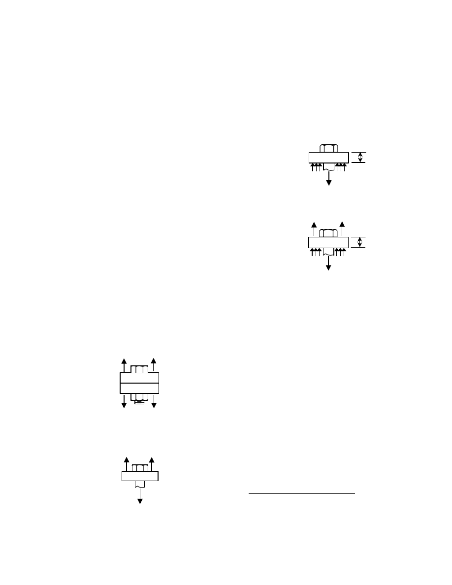
37
Chapter 6
Bolts in Tension
6.1 Introduction
Connection configurations that place bolt groups into
tension were first described in Section 1.4 (Types of
Connections). In this Chapter, the connection of a tee-
stub to a column flange (see Fig. 1.4(b)) will be used to
discuss the issues. Two questions arise: (1) what is the
relationship between the externally applied tensile load
and the bolt pretension and (2) what force is carried by
each bolt corresponding to the externally applied load, P.
6.2 Single Fasteners in Tension
Non-pretensioned bolts
A single bolt connecting two
plates (infinitely stiff) that are loaded by an external
force, P, is shown in Fig. 6.1(a). If the bolt has not been
pretensioned, then the free-body diagram shown in
Fig. 6.1(b) applies. This confirms that the single bolt
shown must resist all of the external load that is applied to
the part. The bolt simply acts like a small tension link and
the least cross-sectional area should be employed to
determine its capacity. Since the bolt is threaded, some
reduced area (as compared with the unthreaded body
portion of the bolt) must be used, and, because the thread
is a spiral, the reduced area is greater than an area taken
through the thread root. A notional area, the tensile stress
area (
st
A
), that will accommodate this was introduced in
Chapter 1 as Eq. 1.1. Hence the capacity of a single bolt
that has not been pretensioned is simply the product of
the tensile stress area and the ultimate tensile strength of
the bolt, i.e.,
u
st
ult
A
R
σ
=
(6.1)
If the bolt in Fig. 6.1 is preloaded, the question arises
as to whether the pretension and the force in the bolt that
is the result of the external loading add in some way.
Pretensioned bolts
Tightening the nut produces a
tension force in the bolt and an equal compression force
in the connected parts. The free-body diagram of
Fig.
6.2(a) (bolt pretensioned but no external load
applied) shows that
b
i
T
C
=
(6.2)
Figure 6.2(b) shows a free-body of the bolt, the
adjacent plates, and an external load, P, that is applied to
the connected parts. In this free-body, the tensile force in
the plate and the compressive force in the plate are
identified those corresponding to final conditions,
f
f
C
and
T
, respectively. The term of interest is the final
bolt tension, i.e., by how much does the force in the bolt
increase over its initial pretension value when the external
load, P, is applied. This free-body indicates that
f
f
C
P
T
+
=
(6.3)
The plates and the bolt can be assumed to remain
elastic,
1
and consequently the elongation of each
1
The bolt will yield when pretensioning takes place, but
the yielding is present only within a small portion of the
total bolt volume. The assumption that the bolt is elastic
is reasonable for the issue under examination.
Fig. 6.1(a) Single Bolt
and Tensile Force
P/2
P/2
P/2
P/2
Fig. 6.1(b) Free Body
Diagram
P
P/2
P/2
Fig. 6.2(a) Free Body:
No External Load
T
b
C
i
t
Fig. 6.2(b) Free Body:
External Load Applied
T
f
C
f
t
P/2
P/2
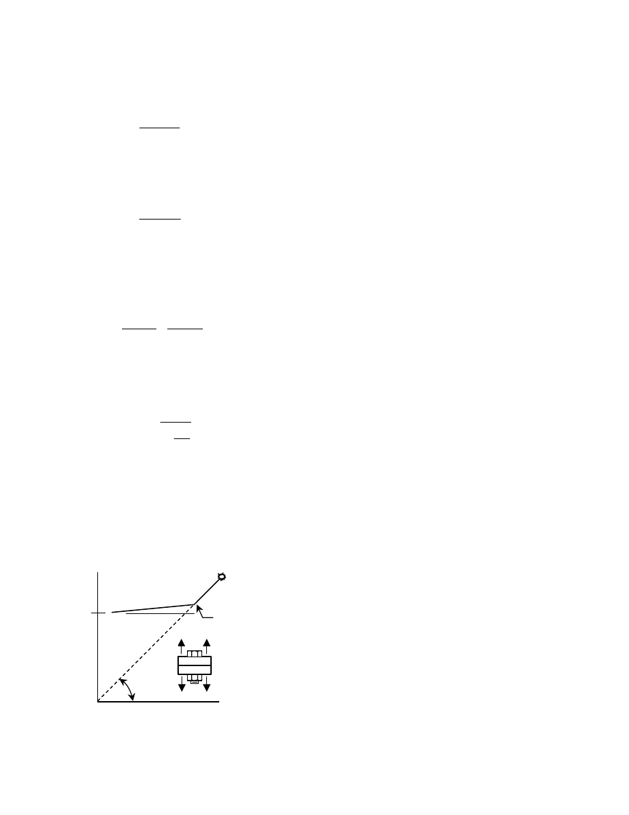
38
component as the external force is applied can be
calculated. The elongation of the bolt over a length equal
to the thickness of one plate, t, is
(
)
t
E
A
T
T
b
b
f
b
−
=
δ
(6.4)
As the external force is applied, the contact pressure
between the plates, initially at a value
i
C
, decreases to
some value
f
C
. During this process, the plate expands by
an amount
(
)
t
E
A
C
C
p
f
i
p
−
=
δ
(6.5)
where
p
A
is the area of plate in compression and is that
associated with one fastener.
If the plates have not separated, compatibility
requires that
p
b
δ
≡
δ
. Using Eq. 6.4 and 6.5, this means
that
p
f
i
b
b
f
A
C
C
A
T
T
−
=
−
Using the value of
i
C
from Eq. 6.2 and the value of
f
C
that can be obtained from Eq. 6.3, and after some
algebraic manipulation, the final bolt force can be
obtained:
b
p
b
f
A
A
1
P
T
T
+
+
=
(6.6)
Equation 6.6 says that the final bolt force,
f
T
, is the
initial pretension force,
b
T
, plus a component of the
externally applied load that depends on the relative areas
of the bolt and the area of the connected material in
compression. Of course, the latter is not unique and there
are other assumptions in the derivation of Eq. 6.6.
However, test results [50] show that Eq. 6.6 is a good
predictor and that the increase in bolt pretension can be
expected to be in the order not more than about 5% to
10%.
After the parts have separated, Eq. 6.6 no longer
applies and the situation is simply that corresponding to
Fig. 6.1(b), i.e., the bolt must carry all of the externally
applied force. In total, the response of the bolt to external
load is that shown in Fig. 6.3.
The LRFD rules for the design of high-strength bolts
acting in tension can now be described. The small
increase in bolt force that will occur as service loads are
applied is ignored. After the parts separate, the ultimate
strength is that given by Eq. 6.1. The AISC LRFD
Specification tabulates permissible stresses for A325 and
A490 bolts in tension: it is intended that these permissible
stresses be multiplied by the cross-sectional area of the
bolt corresponding to the diameter. Because it is
convenient for the designer to not have to calculate the
stress area, the difference between this nominal area and
the stress area is accommodated by use of a multiplier.
For most structural bolt sizes, the relationship between
the two areas is about 0.75.
The nominal tensile strength according to the LRFD
Specification (Clause J3.6) is
u
b
n
F
A
75
.
0
R
=
(6.7)
which is a direct reflection of Eq. 6.1. The LRFD
Specification requires that the resistance factor to be
applied to
n
R
is
.
75
.
0
=
φ
The resistance factors
recommended in [22] are 0.85 and 0.83 for A325 and
A490 bolts, respectively. However, these recom-
mendations are for bolts loaded using laboratory testing
machines: similar bolts in real connections could have
some bending present. Nevertheless, the LRFD
Specification recommendation (
75
.
0
=
φ
) appears to be
conservative.
The remaining question, how much force is carried
by a bolt in a connection of real components, is addressed
in the next section.
6.3 Bolt Force in Tension Connections
In the previous section, the resistance of a single bolt to
an externally applied load was identified. In this section,
the effect of the externally applied load acting upon a bolt
group in which tensile forces develop will be examined.
The need for this examination arises because the
deformation of the connected parts can produce forces in
the bolts that are larger than the nominal values. For
instance, the tee-stub connection shown in Fig. 6.4—
which is a component of the connection shown in Fig.
1.4(b)—has four bolts connecting the flange of the tee to
the column flange shown. It would normally be expected
that the load per bolt is P/4. However, deformation of the
connected parts can produce loads significantly greater
than this.
Fig. 6.3 Bolt Force vs. Applied Load
Force
in Bolt
T
b
Applied Load, P
bolt
fracture
separation of
connected
parts
45
°
P
P
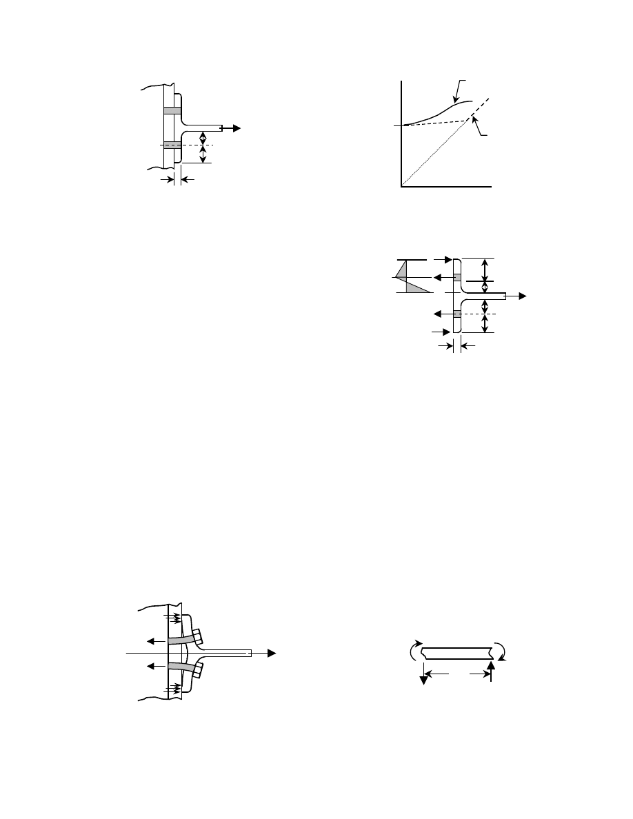
39
Figure 6.5 shows the tee stub in a deformed
condition. The drawing exaggerates the deformation, but
it identifies that the tee stub flange acts like a lever upon
the bolts. This result is termed prying action. Obviously,
the amount of prying depends upon the stiffness of the
flange, among other factors. If the flange is very stiff,
then the bolt force vs. applied load relationship will be
like that in Fig. 6.3, which was for a single bolt loaded by
an external force that acted upon an infinitely stiff part. If
the flange is relatively flexible, then the relationship can
be like that shown in Fig. 6.6. In addition to the stiffness
of the flange, the other factors than can have the most
significant effect upon the amount of prying are the bolt
deformation capacity and the location of the bolt in the
tee-stub flange (i.e., the dimensions a and b in Fig. 6.4).
Various models have been developed to quantify the
bolt prying force. They are reviewed in Reference [6],
where the model recommended is the one that was
selected for use in the LRFD Manual [51]. Figure 6.7
shows the geometry of the model. It should be evident
that selection of the dimension b should be as small as
practicable (which will be for wrench clearance, mainly)
so as to minimize the prying force, Q.
Summation of the forces gives
0
B
Q
T
=
−
+
(6.8)
A free-body taken from the flange tip to the
centerline of the bolt (not shown) shows that
a
Q
M
2
⋅
=
(6.9)
Next, a free-body of the flange between the face of
the tee-stub web and the bolt line (Fig. 6.8) and a
summation of moments gives
0
b
T
M
M
2
1
=
⋅
−
+
(6.10a)
The moments
1
M
and
2
M
act on different cross-
sections, the former on the gross cross-section of the
flange and the latter on the net cross-section, i.e., a cross-
section taken through the bolt holes. In order to normalize
Eq. 6.10(a), the moment
2
M
will be multiplied by the
ratio
=
δ
net cross-section / gross cross-section. Thus,
Eq. 6.10(a) should be rewritten as:
0
b
T
M
M
2
1
=
⋅
−
⋅
δ
+
(6.10b)
Also, it will be convenient to describe
2
M
as a fraction,
α , of
1
M
, where
0
.
1
0
≤
α
≤
:
0
b
T
M
M
1
1
=
⋅
−
⋅
δ
⋅
α
+
Solving for the moment
1
M
:
Fig. 6.5 Tee-Stub in
Deformed Condition
Fig. 6.4 Tee-Stub
Connection
b
a
t
f
P
Force
in
Bolt
T
b
Applied Load
with no
prying
Fig. 6.6 Bolt Force vs. Applied Load,
Prying Present
with prying
present
b
a
t
Fig. 6.7 Prying Action Nomenclature
b'
a'
2T
Q
B (=T+Q)
Q
M
1
M
2
M
2
M
1
B
b
Fig. 6.8 Free-body Diagram
T
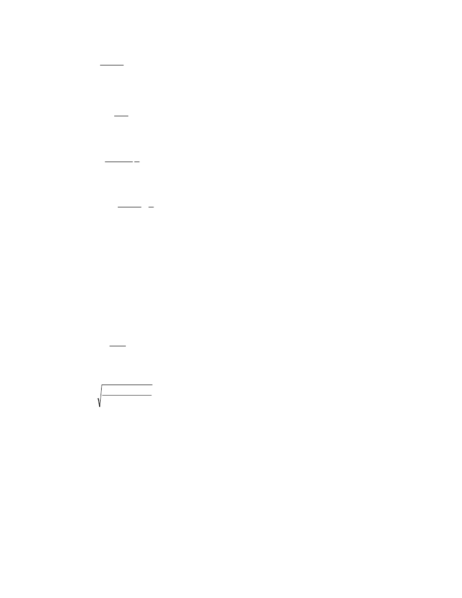
40
δ
⋅
α
+
⋅
=
1
b
T
M
1
(6.11)
Equation 6.9 can now be rewritten as
a
Q
M
1
⋅
=
⋅
δ
⋅
α
or,
1
M
a
Q
δ
⋅
α
=
Substitute the value of
1
M
according to Eq. 6.11 to
obtain the prying force
(
)
T
a
b
1
Q
δ
⋅
α
+
δ
⋅
α
=
and then use Eq. 6.8 (B = T+Q) to obtain the final bolt
force as
δ
⋅
α
+
δ
⋅
α
+
=
a
b
1
1
T
B
(6.12)
Reference [6] suggests using the dimensions a' and b'
(Fig. 6.7) instead of a and b. This improves the agreement
against test results and is slightly less conservative.
The result obtained using Eq. 6.12 can now be used
to establish whether the bolt is adequate, in accordance
with the LRFD Specification requirements (i.e., Eq. 6.7
multiplied by a resistance factor, which was also
expressed as Eq. 4.1). A concomitant requirement is that
the flexural strength of the tee-stub flange be adequate.
The plastic moment capacity,
y
p
F
Z
M
φ
=
φ
, is available
since local buckling is not an issue. For a flange length w
tributary to one bolt, this moment capacity is
y
2
f
F
4
t
w
φ
Setting this resistance equal to
1
M
as given in Eq. 6.11
and solving for the flange thickness required—
(
)
δ
⋅
α
+
φ
=
1
F
w
b
T
4
t
y
f
(6.13)
Again, it is recommended that the dimensions a' and
b' shown in Fig. 6.7 be used.
Examination of the connection strength using
Eq. 6.12 and 6.13 requires knowledge of the value of
α ,
which identifies the relationship between
1
M
and
2
M
.
(If
0
.
1
=
α
, then there is a plastic hinge at each of the
1
M
and
2
M
locations (Fig. 6.7), and the prying force is
a maximum. If
0
=
α
, then of course there is no prying
action.) Information that is helpful regarding practical
aspects of the use of Equations 6.12 and 6.13 is available
in [51 and 52].
Often, it will be expedient to identify the plate
thickness for which there will be no prying, i.e.,
0
=
α
. If
this plate thickness is acceptable in practical terms, then
of course no further action is required except to ensure
that the bolt chosen is large enough to carry the force T.
The issue of prying action is particularly important
when the connection is subjected to fatigue. Chapter 7
should be consulted in this case.

41
Chapter 7
FATIGUE of BOLTED and
RIVETED JOINTS
7.1 Introduction
High-strength bolted joints are often used in new
structures when repetitive loads are present. Such
situations include bridges, crane support structures, and
the like. In many cases, the bolts will be in shear-type
connections, and experience shows that the fatigue failure
mode can be present in either the gross or net cross-
section of the connected material. There are no reported
instances of fatigue failure of the fasteners themselves
when high-strength bolts are used in shear-type
connections. However, in the case of connections that
place the bolts in tension a potential failure mode is
indeed fatigue failure of the bolts.
The case of fatigue life of riveted connections is of
interest because of the need to establish the remaining
fatigue life of existing structures that were fabricated in
this way. Because of corrosion, old riveted structures,
especially bridges, are unlikely to have the sound rivet
heads that would be necessary to sustain fatigue in the
axial direction of the rivet. In such cases, the rivets should
be replaced by high-strength bolts. Consequently, the only
case that will be discussed here is that for riveted joints
loaded in shear.
Notwithstanding the distinction set out between
fatigue of rivets or bolts in shear-type connections and
rivets or bolts in tension-type connections, there are
situations where both shear and tension are present. These
cases are often inadvertent and arise because of
deformation of connected parts, or because of forces
actually present but which have not been calculated by the
designer. For example, a floor beam connected
transversely to a girder by means of riveted or bolted web
framing angles will be treated by the designer as a shear-
only connection. Nevertheless, some moment will be
present, particularly if the angles are relatively deep.
Thus, a bolt or rivet designed only for shear will also have
some tension present. This usually is not significant for
strength, but it can show up as a fatigue failure in the
fastener. This situation will not be treated here: the reader
can obtain more information in References [53, 54].
7.2 Riveted Joints
The experimental evidence is that fatigue cracking in
riveted shear splices takes place in the connected material,
not in the rivet itself. Consequently, the fatigue life can be
expected to be a reflection of such features as the size of
the hole relative to the part, the method of hole forming
(drilled, punched, or sub-punched and reamed), the
bearing condition of the rivet with respect to the hole, and
the clamping force provided by the rivet. At the present
time, the influences of clamping force, bearing condition,
and the method of hole formation have not been examined
in any systematic way. The influence of the hole size, per
se, is not likely to be strong, as long as the hole sizes and
plate thicknesses commonly used in structural practice
pertain. Thus, the best data available are tests on riveted
connections of proportions that are consistent with usual
structural practice and are of full size, or at least large
size. For the time being, the effects of clamping force,
bearing condition, and hole formation must simply be part
of the data pool. For this reason, and because the "defect"
presented by a riveted connection is not severe, it is to be
expected that the scatter of data will be relatively large.
Figure 7.1 shows the experimental data, given here
using SI units. Identification of the specific sources from
which the test data came can be obtained in Reference
[55]. Most of the data come from tests of flexural
members, and most of these were members taken from
service. For those cases where members taken from
service were tested, the previous stress history was
examined and deemed to have been non-damaging. A few
of the test results are from tension members. In the case of
bending members, the moment of inertia of the cross-
section included the effect of holes. For the tension
members, the stress range was calculated on the net cross-
section. (It is not yet clear whether this is justified. In the
tests, it was observed that the fatigue cracks grew at right
angles to the cross-section when staggered holes were
present.)
It is usual to establish the permissible fatigue life for
a welded detail as the mean of the test data less two
standard deviations of fatigue life [53]. In the case of both
riveted and bolted connections, however, there is a great
deal of scatter in the results and the fatigue life line is
selected more as a matter of judgment. Figure 7.1 shows
the permissible stress range for riveted shear splices
according to both the AISC LRFD specification [17] and
the AASHTO Specification [19]. In both cases, the net
cross-section of the member must be used to calculate the
stress range.
The permissible stress range is the same (Category
D) for the two specifications in the initial portion of
Fig. 7.1, but there is a major difference in the long-life
region. For the LRFD Specification, the horizontal dotted
line in Fig. 7.1 at the stress range value of about 50 MPa
(7 ksi) is the controlling feature in this region of fatigue
lives greater than about 6 million cycles. The AASHTO
Specification prescribes the same value, but then
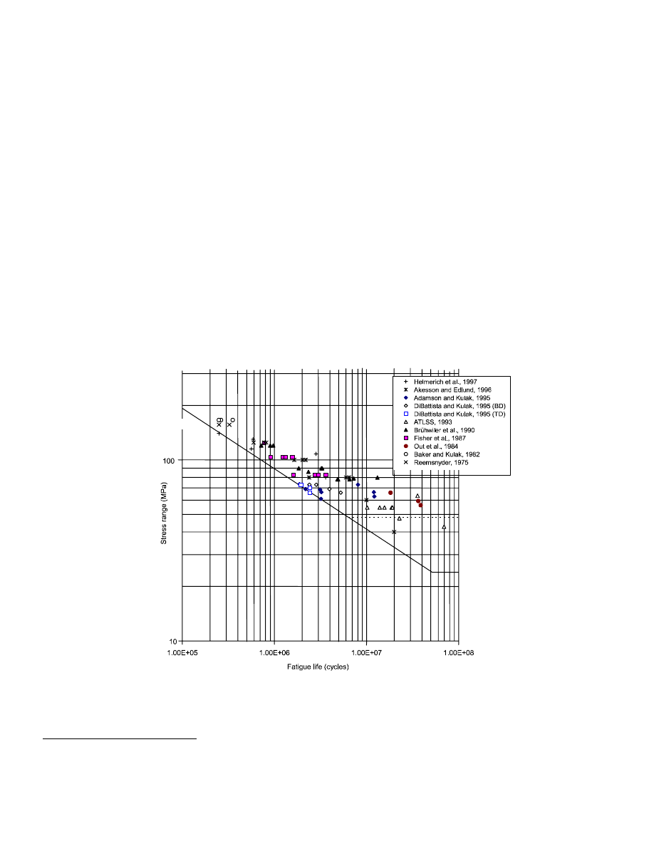
42
effectively discounts it by a factor of 2. As seen in Fig.
7.1, the AASHTO threshold stress
1
range does not start
until about 50 million cycles. The adjustment is made in
order to account for the presence of occasional stress
ranges greater (by a factor of 2) than those corresponding
to the calculated equivalent stress range [53]. This is
reasonable and is consistent with the effects of observed
highway truck traffic. Thus, the threshold stress in the
AASHTO Specification is one-half of that used in the
LRFD Specification.
The implication of the LRFD rules, specifically the
selection of the constant amplitude fatigue limit at a value
of 7 ksi, is that the calculated stress ranges must be known
exactly. If only a small fraction of the actual stress ranges
exceed the CAFL, then fatigue cracking can take place
[52]. Thus, when applying the LRFD rules, the designer
must ensure that the calculated stress ranges in the long-
life region will always be below the CAFL. One way of
doing this is to use conservative assumptions regarding
the applied forces. (As discussed above, the AASHTO
Specification handles this by a two-fold increase in the
fatigue load.) It can also be observed (Fig. 7.1) that there
are some test data at or below the LRFD threshold limit.
1
Also called constant amplitude fatigue limit, or CAFL,
in the literature.
7.3 Bolted Joints
High-strength bolted joints can be subdivided into two
categories; those that are lap or butt splices ("shear
splices") and those that are tension-type connections. In
the former case, the bolts can be either pretensioned or
not pretensioned, although in new construction most
specifications require that the bolts be pretensioned if
fatigue loading is likely. It has always been common
practice in bridge construction to use pretensioned bolts.
7.3.1 Bolted Shear Splices
The fatigue strength of a bolted shear splice is directly
influenced by the type of load transfer in the connection.
This load transfer can be completely by friction at the
interface of the connected parts (slip-critical case,
pretensioned bolts), completely by bearing of the bolts
against the connected material (non-pretensioned bolts),
or by some combination of these two mechanisms. In the
case where the load transfer is by friction, fretting of the
connected parts occurs, particularly on the faying surfaces
near the extremities of the joint. Here, the differential
strain between the two components is highest and,
consequently, minute slip takes place in this location as
load is applied repetitively. Cracks are initiated and grow
in this region, which means that cracking takes place
ahead of the first (or last) bolt hole in a line, and the crack
progresses from the surface down through the gross cross-
Fig. 7.1 Fatigue of Riveted Connections
AASHTO and LRFD
LRFD
AASHTO

43
section of the component. The phenomenon is referred to
as "fretting fatigue."
If the bolts are not pretensioned, load transfer is by
shear in the fasteners and an equilibrating bearing force in
the connected parts. The local tensile stress in the region
of the connected part adjacent to the hole is high, and this
is now the location where fatigue cracks can start and
grow. Some point at the edge of the hole or within the
barrel of the hole is the initiation site for the fatigue crack,
and growth is through the net cross-section of the
connected part.
Both types of fatigue crack behavior have been
observed in laboratory tests and, in a few cases, both
types have been observed within the same test. If non-
pretensioned bolts are used, it is highly unlikely that
fretting fatigue will occur, however. When pretensioned
bolts are used, it is prudent that the designer check both
possible types of failure.
It is worth noting again that there is no history of fatigue
failure of high-strength bolts themselves in shear splices.
Only the connected material is susceptible to fatigue
cracking.
The AISC LRFD Specification permissible stress
range for bearing-type connections (bolts not
pretensioned) is the same as it is for riveted connections,
as would be expected. This can be seen in Fig. 7.1 (the
sloping straight line that changes to a horizontal straight
line at about 6 million cycles). The stress range must be
calculated using the net section of the member. The
AASHTO rule for this case also follows what was
prescribed by AASHTO for riveted connections, i.e., the
sloping straight line down to 50 million cycles, followed
by a horizontal straight line portion. The reason for the
difference in how the two specifications handle the long-
life region was discussed in Section 7.2, where some
cautionary comments for users of the LRFD Specification
were provided.
For slip-critical splices, AASHTO prescribes Category
B. In this case, the gross cross-section is used to calculate
the stress range. Category B (not shown here) is a sloping
straight line until it meets a horizontal straight line at 55
MPa (8 ksi). This junction is 23.6 million cycles. If the
joint is high-strength bolted but not designed as slip-
critical, then the net cross-section is to be used in the
calculations. However, in practice it is likely that all joints
in a bridge will be designed as slip-critical.
The LRFD Specification also uses Category B for
slip-critical joints, but again the horizontal cut-off is twice
as large as that used in AASHTO. In this case, it is 110
MPa (16 ksi), which occurs at about 3 million cycles.
Selection of Category B for both LRFD and AASHTO
reflects the superior fatigue life characteristics of a bolted
splice that is designed as slip-critical.
There are many examples where fatigue cracking is
the consequence of out-of-plane deformations [53, 54].
This is referred to as displacement-induced fatigue
cracking. The AASHTO Specification provides guidance
for such situations, but the LRFD Specification is silent
on this topic. Elimination of displacement-induced fatigue
cracking is largely a matter of good detailing, which is a
difficult thing to quantify. However, both the AASHTO
Specification [19] and References [53 and 54] are helpful
sources. Designers are reminded that meeting the rules for
force-induced fatigue design, as has been discussed in this
chapter, does not eliminate the need to examine the
possibility of distortion-induced fatigue cracking.
7.3.2
Bolts in Tension Joints
Although there are few, if any, reported fatigue failures of
high-strength bolted shear splices, fatigue failures of high-
strength bolted tension-type connections have occurred
from time to time. Fortunately, it is unusual to use
tension-type connections in bridges and other repetitively
structures loaded structures. The experimental data upon
which to base design rules are not very numerous,
however.
Connections that result in bolts in tension were
illustrated in Fig. 1.4. A significant feature of the
connection is that prying forces develop, and it was
explained in Chapter 6 that this places an additional force
in the bolt, thereby increasing the nominal tension value
(i.e., the total external force divided by the number of
bolts). The amount of the prying force is dependent upon
the flexibility of the connection. The same flexibility
introduces bending into the bolt, and this can also affect
the fatigue life of the bolt. The threaded portion of the
bolt provides the crack initiation location, which as a rule
is at the root of a thread. It should be noted that the
predictions for prying force given in Chapter 6 are based
on conditions at ultimate load. The level of prying force at
service load levels, which is where fatigue takes place,
has not been established by either analysis or tests.
The stress range experienced by the bolt as the
assembly undergoes repeated loading is significantly
affected by the level of bolt pretension [6]. At one
extreme, properly pretensioned bolts in a very stiff
connection will undergo little or no stress range and will
therefore have a long fatigue life. On the other hand, if the
connection is relatively flexible, bolt bending is present,
and the bolt pretension is low, then the stress range in the
bolt threads will be large. Bolts in this condition will have
a short fatigue life. An additional complication occurs if
the applied load is high enough to produce yielding in the
fasteners. In this case, it has been shown that the stress
range increases with each cycle [6].
The available test data are in References [56 and 57].
Fatigue was not the primary purpose of either
experimental program and the test parameters that relate
to fatigue are limited. The tests did show that the actual
stress range in a bolt that is properly pretensioned and
where the prying forces are small is substantially smaller
than the nominal stress range. (The nominal stress range

44
is the nominal load per bolt divided by the bolt stress
area.)
The AASHTO Specification [19] requirements for
bolts in tension-type connections follow the same general
pattern as that for other details. However, the cases of
ASTM A325 and A490 bolts in tension are not set out as
separate Detail Categories. Instead, the necessary
information for calculating the fatigue life of a high-
strength bolt in tension is simply listed in AASHTO
Tables 6.6.1.2.5–1 and 6.6.1.2.5–3. These tables provide
the constant A and the constant amplitude fatigue stress
for use in the AASHTO fatigue life equations. Other
information concerning fatigue of bolts in tension is given
in AASHTO Article 6.13.2.10.3, where, among other
things, it is noted that the bolt prying force must not
exceed 60% of the nominal force in the bolt. It is also
pointed out that the stress range is to be calculated using
the area of the bolt corresponding to the nominal
diameter. This is simply a convenience that can be
employed because the ratio between the area through the
threads and that corresponding to the nominal diameter of
the bolt is relatively constant for the usual bolt sizes.
The AASHTO rules provide a sloping straight line in
the short life region, followed by a horizontal straight line
at the level of the constant amplitude fatigue limit, as is
usual for all AASHTO details. However, the sloping
straight line portion is short and the constant amplitude
fatigue limit (CAFL) governs for most cases. For both
A325 and A490 bolts, the CAFL starts to govern at only
about 58,000 cycles if the CAFL is taken at its tabulated
value. If the CAFL is divided by 2, as was explained in
Section 7.2, then the sloping straight line intersects the
CAFL/2 line at 458,000 cycles. In either event, the
AASHTO Specification rules capture the test data in a
reasonable way. It can be observed, however, that the test
data do not indicate a differentiation between A325 and
A490 bolts, which is the position taken in AASHTO.
The AISC LRFD Specification [17] treats high-
strength bolts in a tension connection and loaded in
fatigue as a Category E' detail, except that the threshold
stress is to be taken as 7 ksi (Article A–K3.4(b). This
applies to both A325 and A490 bolts, which is consistent
with the test data [56, 57]. The designer has the option of
(1) determining the stress range by analysis, using the
relative stiffness of the various components of the
connection, including the bolts, or (2) by simply taking
20% of the absolute value of the service load. (The stress
range is to be calculated on the tensile stress area of the
bolt.) Given the difficulty of calculating the stress range,
it is likely that designers will use the second option.
In the usual range of interest, say, for >300,000 load
cycles, the AISC Specification 20% rule will give
predictions (permissible stress range for a given number
of cycles) that are significantly conservative. A better
prediction for the available test data could be obtained
using a fatigue life slope that is much less than the value
of
3
−
used in the AISC Specification. Such a choice
would be more like that taken in the AASHTO
Specification.
The fatigue design of high-strength bolts that are in
tension-type connections should reflect the following
guidelines:
• Whenever possible, redesign the connection so that
the bolts are in shear, not tension.
• Ensure that proper installation procedures are
followed so that the prescribed bolt pretensions will
be attained.
• Design the connection so that prying forces are
minimized. The AISC Specification is silent as to
how much prying force is permitted. The AASHTO
rules limit the calculated prying force to 60% of the
externally applied load and the RCSC Specification
[14] says that the limit should be 30%. The writer
recommends that calculated prying be no more than
30% of the externally applied force.

45
Chapter 8
SPECIAL TOPICS
8.1 Introduction
There are a number of issues that may be of interest to
designers but which do not warrant an extensive
discussion here because of the amount of detail involved.
The specifics can be obtained more expeditiously by
reviewing the relevant specifications as required. The
miscellaneous subjects include the need for washers, use
of oversized or slotted holes, use of particularly short or
particularly long bolts, galvanized bolts and nuts, reuse of
high-strength bolts, joints that combine bolts and welds,
and coated faying surfaces. The short discussions that
follow are intended mainly to alert the designer to the
issues involved and to potential problems.
8.2 Use of Washers in Joints with Standard Holes
The AISC LRFD Specification [17] depends upon the
specification of the Research Council on Structural
Connections (RCSC) [14] for most matters associated
with high-strength bolts and their installation. The RCSC
Specification requires that a standard, hardened washer,
ASTM F436 [16] be used under the turned element when
calibrated wrench pretensioning or twist-off type bolt
pretensioning is to be used. (A washer is not required
under the non-turned element for these cases.) This
requirement reflects the need to have a hard, non-galling
surface under the turned element when installation is
based on measurement of torque.
A washer is also required for the installation of bolts
that use washer-type direct tension indicators (DTI's).
Although this is not a torque-controlled method of
installation, there are reasons specific to the way this
installation is performed that means that washers are
usually required. These reasons include the necessity that
the protrusions on the DTI washer bear against a hardened
surface and the need to prevent the protrusions on the DTI
washer from wearing down by scouring, as could be the
case if a nut or bolt head is turned directly against the
protrusion side of a DTI washer. Washers are not required
when the DTI washer is placed against the underside of
the bolt head if the head is not turned, however. Specific
information as to the location of the washer can be
obtained in Article 6.2.4 of the RCSC Specification.
Another helpful source for identifying washer locations
when DTI's are used (and other similar bolting detail
information) is Reference [58].
When snug-tightened joints are used, washers are not
required, except as noted below. Likewise, for
pretensioned or slip-critical joints, washers are not
required if the installation is by the turn-of-nut method.
There are certain exceptions, and these are noted as
follows:
•
If sloping surfaces greater than 1:20 are present, an
ASTM F436 bevelled washer must be used to
compensate for the lack of parallelism. This applies
to all methods of bolt installation and all joint types.
•
It is also required that washers be present when
A490 bolts are used to fasten material that has a
yield strength less than 40 ksi. This is because
galling in the connected material under the nut can
occur when softer material is fastened by these
bolts. However, the only steel grade likely to fall
into this category is ASTM A36, and this is used
less and less for steel shapes. It is still used for
angles and plates, however.
•
Washers are often required for joints that use slotted
or oversized holes, regardless of the type of joint or
method of installation. This is discussed in
Section 8.3.
Fastener components are typically supplied by the
manufacturer or distributor as separate items, i.e., bolts,
nuts, and washers. Assembly of the components into
"sets" is sometimes done at this point in order to make it
convenient for the installer of the assembly. If washers
are not, in fact, required by the specifics of the
application, using these washers means that the time
required to place the bolts will be slightly increased
because of the extra handling required in the installation.
On the other hand, using washers throughout a job means
that the erector does every joint in a consistent manner. If
this is the method chosen, it is at least worthwhile that the
inspection process reflect whether washers were actually
needed.
8.3 Oversized or Slotted Holes
The use of oversized or slotted holes can be of great
benefit to erectors because their use allows more tolerance
when placing the components of the assembly. The
question to be addressed here is the effect that oversized
or slotted holes might have upon the expected
performance of the connection.
The standard hole size for high-strength bolts is 1/16
in. greater than the nominal diameter of the bolt to be
used. Particularly in joints that have many bolts, it is
possible that not all holes in one component will line up
exactly with the holes in the mating material. However, if
oversized holes are used, omni-directional tolerance
exists. If slotted holes are used, a greater tolerance is
provided than for oversized holes, but this tolerance is
mainly in one direction, the direction of the slot. The
effect of oversized or slotted holes upon net section is

46
taken into account directly in the design calculations
because the oversized hole or slot dimensions will be
used. Therefore, the concern becomes one relating to the
bolt behavior—will the bolt in a slotted hole or an
oversized hole be reduced in capacity as a consequence.
For the case of snug-tightened joints only, when
slotted or oversized holes are used in an outside ply,
either an ASTM F436 washer or a 5/16 in. thick common
plate washer is required.
If the joint is either pretensioned or slip-critical, then
washer requirements reflect the fact that intended bolt
pretensions may not be attained with standard washers.
Tests have shown that both oversized and slotted holes
can significantly affect the level of preload in the bolt
when standard installation procedures are used. Consider
an oversized hole, for example. As a hole becomes larger
relative to the bolt diameter, the amount of material
remaining to react the force in the bolt is reduced.
Consequently, the connected material around the
periphery of the hole is under higher contact stresses than
would otherwise have been the case. This is exacerbated
if the bolt head, nut, or washer actually scours the
connected material. The situation is similar when slotted
holes are used. As a result, the amount of bolt elongation
(and, pretension) for a given turn-of-nut will be less than
if a standard hole were present.
Tests have shown that using standard washers, which
are 5/32 in. thick
1
, often does not permit the expected bolt
pretensions to be attained when oversized or slotted holes
are used. A greater washer thickness (i.e., stiffness) is
required to bridge the opening and enable the delivery of
normal pretensions. The RCSC Specification does permit
F436 washers for a certain number of cases—all
diameters of A325 bolts and A490 bolts
≤
1 in. diameter
when oversized or short-slotted holes are present in the
outer plies of a joint. However, when a long-slotted hole
is used in the outer ply, a 5/16 in. thick plate washer or
continuous bar is required. For the case of A490 bolts >1
in. diameter and oversized or short-slotted holes in an
outer ply, an ASTM F436 washer with 5/16 in. thickness
is required. If the A490 bolt is used when a long-slotted
hole is present in the outer ply, then a 5/16 in. thick
hardened plate washer or hardened continuous bar is
required. It should be noted that, in all cases, building up
to a required thickness by simply stacking standard
washers is not sufficient. The requirement to be met is
one of stiffness, not thickness per se.
1
ASTM A436 washers have a maximum permitted
thickness of 0.177 in. for all bolt diameters, but the
minimum permitted thickness is a function of the bolt
diameter. A reasonable average value for the thickness is
usually taken as 5/32 in. (0.156 in.).
8.4 Use of Long Bolts or Short Bolts
Long or short bolts not required to be pretensioned do not
require special attention. However, when pretension is
required, the use of particularly long or short bolts should
be scrutinized.
The bulk of the research used initially to formulate
the rules for the installation of high-strength fasteners was
done using bolts where the length was generally in the
range from about 4 bolt diameters up to about 8 diameters
[6]. Subsequently, it was found that if the bolts were
shorter than this, then the installation process could
produce torsional failure of the bolts or thread stripping
before installation had been completed. At the other end
of the spectrum, the use of long bolts means that more
elastic relaxation will be present and this may degrade the
pretension. For very long bolts, there simply is not
enough research background for satisfactory standard
pretensioning and installation rules to be set forth and
preinstallation testing is required. Again, these concerns
about short or long bolts apply only when pretension is
required.
The RCSC Specification requires that short bolts
required to be pretensioned according to the turn-of-nut
process be given 1/3 turn instead of the usual 1/2 turn.
This applies to bolts whose length is up to 4 diameters. If
other methods of installation are chosen, e.g., calibrated
wrench, use of direct tension indicating washers, or
tension-control bolts, then the length effect will be
captured in the preinstallation testing. A problem can
arise with particularly short bolts, such as may be used in
tower construction, however. Depending on the size of the
Skidmore-Wilhelm calibrator, it may not be possible to
properly fit the bolt into the calibrator. Either new fittings
must be used to adapt the calibrator to the short bolts, or
calibrated direct tension indicating washers be used, or a
solid block device that measures load using strain gages
can be improvised.
In the case of long bolts that must be pretensioned, if
the turn-of-nut method is used and the bolts are between 8
diameters and 12 diameters, then 2/3 turn should be used.
Bolts greater than 12 diameters long have not been
subjected to sufficient testing to establish rules. For long
bolts that will be installed by calibrated wrench or by use
of direct tension indicating washers or as tension-control
bolts, calibration using the Skidmore-Wilhelm device is
easily accomplished by the addition of solid material
sufficient to increase the grip length.
8.5 Galvanized Bolts
In order to provide corrosion protection, it is sometimes
advantageous to apply a zinc coating to structural steel,
i.e., to galvanize the material. In these cases, it is usually
the practice to use galvanized fasteners as well. In
ordinary conditions, the high-strength bolts themselves do
not exhibit very much corrosion, and it is generally
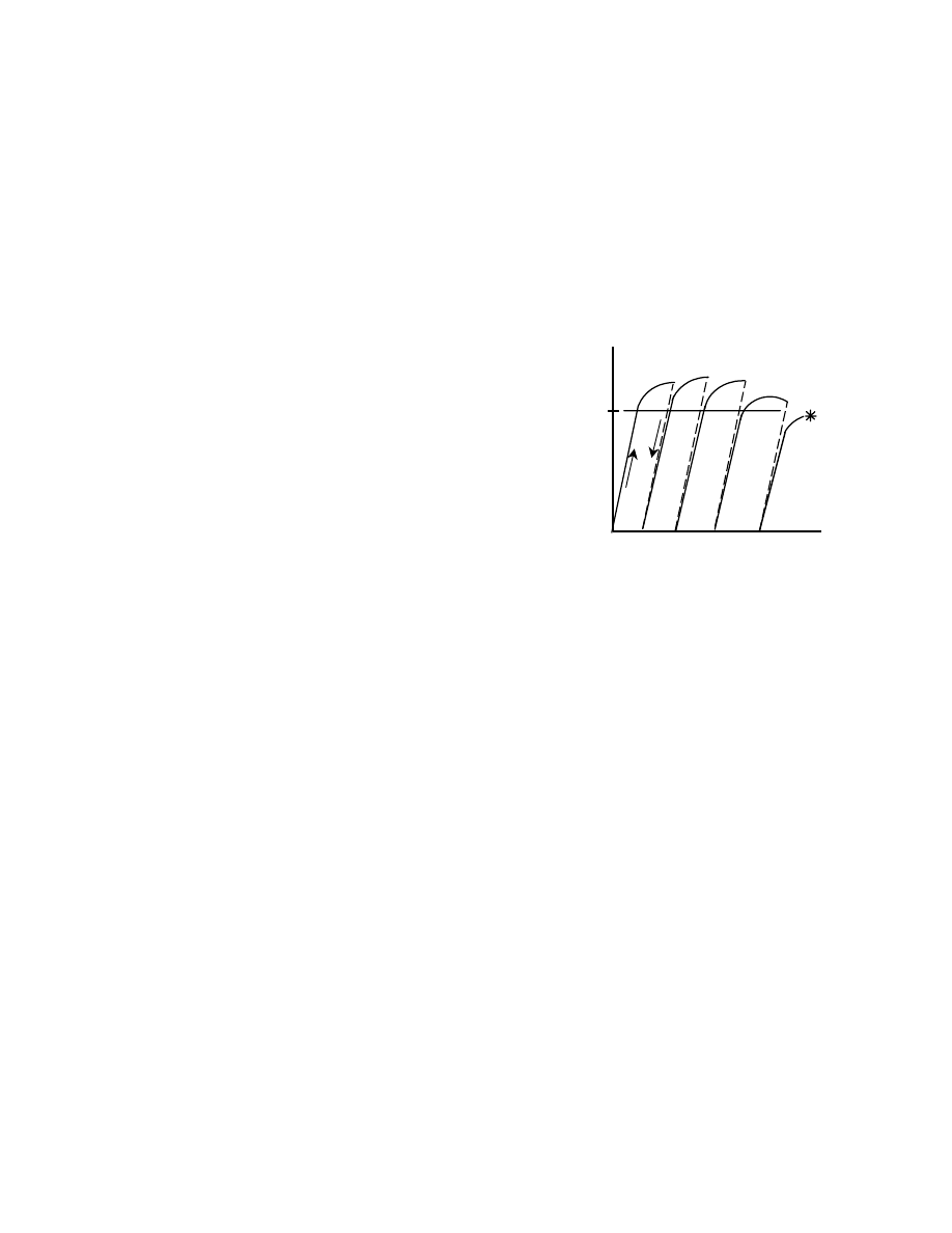
47
unlikely that corrosion protection of the bolts is necessary
for most building construction unless there is exposure to
a marine atmosphere. The industrial atmosphere of some
plants may make it desirable to galvanize high-strength
bolts in these cases also. In no instance should A490 bolts
be galvanized, however, because their high strength then
makes them susceptible to hydrogen embrittlement.
The effects of galvanizing A325 bolts is discussed in
this section. The effect of galvanizing the connected
material is examined in Section 8.8.
The issues raised when a bolt and nut are galvanized
include any possible effect on the strength properties of
the bolt, the potential for nut stripping because of thread
overtapping, and the influence of the zinc coating on the
torque required for installation.
Research has shown that galvanizing has no effect on
the strength properties of the bolt [6].
The friction between the bolt and nut threads is
increased when a bolt and nut are galvanized. The
galvanizing has two effects. First, it increases the
variability of the relationship between applied torque and
resultant pretension. At the extreme, a galvanized bolt and
nut can twist off before the desired pretension has been
attained. Second, thread stripping can occur before
installation is complete as a result of large friction forces.
In order to identify and resolve any potential problems
resulting from galvanizing, ASTM A325 requires that the
nut be lubricated and that the assembly be tested to ensure
that stripping will not occur at a rotation in excess of that
which is required in installation or that twist-off will not
take place before the installation is complete.
Overtapping of the nut will usually be done by the
manufacturer in order that the coated nut and coated bolt
will still assemble properly. This can also be a source of
thread stripping. Compliance of the assembly with the
rotation test required by the A325 specification will
certify that the delivered assembly will perform
satisfactorily.
Compliance with all of the relevant requirements of
both ASTM A325 and the RCSC Specification will
ensure that galvanized bolts and nuts will give satisfactory
performance. These requirements include; (1) the
galvanized bolts and nuts and washers, if required, must
be treated as an assembly, (2) the nuts must have been
lubricated and tested with the supplied bolts, (3) the nuts
and bolts must be shipped together in the same container,
and (4) the supplier is not permitted to supply bolts and
nuts that came from different manufacturing sources.
8.6 Reuse of High-Strength Bolts
Occasionally, a bolt that has been installed during the
erection process has to be removed and then later
reinstalled. This need for reinstallation of bolts might also
come up if a structure is taken down and re-erected in a
new location. The question arises as to whether high-
strength bolts that are required to be pretensioned can be
reused, and, if so, how many times.
A certain amount of yielding takes place when a
high-strength bolt is installed so that the minimum
required pretension is equaled or exceeded. Yielding is
confined to a relatively small volume of material located
in the threaded region just under the nut. This small
amount of yielding is not detrimental to the performance
of the bolt [6]. However, if the bolt pretension is
subsequently decreased to zero, e.g., the bolt is loosened,
then the question arises as to whether it can be reused.
The cycle of pretensioning, loosening, and then
pretensioning again means that a certain amount of
ductility is given up during each cycle. If the number of
tightening and loosening cycles is large, then enough
ductility will be exhausted so that, eventually, the desired
pretension cannot be reached before fracture takes place.
Figure 8.1 shows this effect diagrammatically. In the
illustration, the minimum required tension was attained
upon installation followed by three re-installations (turn-
of-nut), but fractured on the fifth attempt.
The research has shown [6] that both A325 and A490
bolts can be reused a small number of times if the water-
soluble oily coating that is usually applied during the
manufacturing process is present. The tests on A325 bolts
showed that at least three or four reinstallations were
successful. However, the tests on A490 bolts showed that
sometimes only one or two reinstallations were attainable.
The RCSC Specification forbids the reuse of both
A490 bolts and galvanized A325 bolts. The number of
reuses permitted for "black" A325 bolts can be
established for a given lot by carrying out a calibration
procedure using a Skidmore-Wilhelm calibrator. Of
course, the number of reuses must be carefully monitored.
As a rule of thumb, if the nut can be made to run freely on
the threads by hand only, then reuse is permissible.
It should also be noted that either A325 or A490 bolts
that have been snugged and then subsequently found to be
loose can be routinely installed as pretensioned bolts. This
Fig. 8.1 Repeated Installation
Bolt
Tension
Elongation
fracture
——
loading
– – –
unloading
minimum
required
tension

48
does not constitute a reuse since thread yielding will not
have taken place. Even touch-up of pretensioned bolts in a
multi-bolt joint should not generally constitute a reuse,
unless the bolt has become substantially unloaded as other
parts of the joint are bolted.
8.7 Joints with Combined Bolts and Welds
It is sometimes necessary to use high-strength bolts and
fillet welds in the same connection, particularly when
remedial work needs to be done. When these elements act
in the same shear plane, the combined strength is a
function of whether the bolts are snug-tightened or are
pretensioned, the orientation of the fillet welds with
respect to the direction of the force in the connection, and
the location of the bolts relative to their holes. The AISC
LRFD Specification provides recommendations for the
design of such connections in Article J1.9. However,
recent research [59, 60] has shown that these recom-
mendations do not give a good prediction of the actual
strength of bolted–welded connections. Although using
existing LRFD rules will give conservative results, they
are not based on a rational model.
The approach outlined in [59 and 60] recommends
that the joint design strength be taken as the largest of the
(1) shear capacity of the bolts only, (2) shear capacity of
the welds only, or (3) shear capacity of the combination
consisting of the fillet welds and the bolts. High-strength
bolts both pretensioned and snug-tight have been explored
in the research.
Based on the results of tests of the various
combinations, the capacity of a combination of high-
strength bolts and fillet welds placed longitudinally with
respect to the force, Reference [60] recommends that
)
resistance
slip
0.25
(
)
resistance
shear
weld
.
long
(
)
resistance
shear
bolt
50
.
0
(
P
n
×
+
+
×
=
(8.1)
The bolt shear resistance, the longitudinal weld shear
resistance, and the slip resistance are all calculations that
are to be made in accordance with the LRFD
Specification, including the resistance factors (which are
not shown in Eq. 8.1).
If bolts and transversely oriented fillet welds are
combined, then the capacity is to be taken as
)
resistance
slip
(0.25
resistance
shear
weld
transverse
P
n
×
+
=
(8.2)
where the transverse weld shear resistance is now used.
Because the amount of deformation that can be
accommodated by a transverse fillet weld prior to fracture
is very small, the contribution of the bolts in shear is
negligible, and is taken here as zero. Once the transverse
weld has reached its ultimate capacity (i.e., when it
fractures), then the situation simply reverts to that of a
bolted joint. This strength may be greater than that given
by Eq. 8.2, depending on the proportion of bolts to trans-
verse weld.
When bolts are combined with both longitudinal and
transverse welds, the capacity is to be taken as
)
resistance
slip
0.25
(
)
resistance
shear
weld
e
(transvers
)
resistance
shear
weld
.
long
85
.
0
(
P
n
×
+
+
×
=
(8.3)
Once again, it is recognized that the transverse weld
will reach its ultimate strength at a relatively small
amount of deformation. Once it breaks, the situation
reverts to that of a longitudinal fillet weld in combination
with high-strength bolts. Now, Eq. 8.1 applies and the
strength calculated in this way could be larger than that
obtained using Eq. 8.3.
Overriding all these cases, it has already been noted
that it is possible that the weld shear strength alone can
govern or that the bolt shear strength alone can govern.
The practical meaning of such a situation is that there can
be no benefit when considering certain combinations of
bolts and welds. These cases will arise when the
proportions of welds and bolts are inappropriate.
Consider, for example, an existing bolted joint to which
only a small amount of longitudinal weld is added. As the
joint is loaded, the bolts are not fully effective in shear,
according to Eq. 8.1. As the longitudinal weld reaches its
ultimate capacity and fractures, the situation reverts to
that of a bolted joint alone. The bolts are now fully
effective and their strength can be greater than the
combined bolted–welded strength. In total, the designer
has to check these situations (bolts alone or welds alone)
plus the appropriate equations among Eq. 8.1, 8.2, and
8.3.
Generally, the addition of transverse fillet welds to a
bolted joint is not an very effective way of strengthening
an existing joint.
8.8 Surface Coatings
In some applications, it is advisable to provide a
protective coating to the surface of the steel used in the
structure. The main reason for doing so is to prevent
corrosion of the steel, either for when the steel is exposed
during the erection phase or for protection on a continuing
basis. Coatings can be paint, a metallic layer of zinc or
aluminum, various kinds of vinyl washes, organic or
inorganic zinc-rich paints, and so on. If the coating is
applied to the surfaces of joints that are designated as
snug-tightened or as pretensioned [14, 17], then the
coating has no influence upon the strength or performance
of the connection. In these cases, the strength of the joint
is determined on the basis of the net section of the
connected material, on the shear strength of the bolts, or
on the bearing strength of the connected material. It is

49
only when the joint is designated and designed as slip-
critical that the coating plays a role.
The design of slip-critical joints was described in
Section 5.2. As explained there, the designer has the
option of designing on the basis of factored loads or by
using the nominal loads. If factored loads are used, then
the slip coefficient of the steel, µ, enters directly into the
design equation (Eq. 5.2). In the LRFD Specification,
faying surfaces are categorized as A, B, or C, and values
are given for the slip coefficient for these surfaces. For
example, a hot-dip galvanized surface that has been
roughened (by light hand wire brushing) is a Class C
surface and a slip value
35
.
0
=
µ
is prescribed. In all
other cases where coatings are used, it is required that
tests be carried out to determine the slip coefficient for
that case. The method of test is given in the RCSC
Specification [14].
If the designer proceeds on the basis of nominal
loads, then the expression for the slip resistance is
expressed in terms of an equivalent shear stress (see
Section 5.2). The LRFD expression in this case is based
on the use of
33
.
0
=
µ
, which is the slip coefficient for an
unpainted clean mill scale surface. However, the designer
has the opportunity here also to use other values by
adjusting the permissible equivalent shear stress to reflect
different slip coefficients, as obtained from the literature
or by tests.


51
REFERENCES
1. Bibliography on Bolted and Riveted Joints, ASCE
Manuals and Reports on Engineering Practice, No.
48, American Society of Civil Engineers, Reston,
VA.,
2. Bibliography on Riveted Joints, A.E.R. deJong,
American Society of Mechanical Engineers, New
York, 1945.
3. C. Batho and E.H. Bateman, "Investigations on Bolts
and Bolted Joints, Second Report of the Steel
Structures Research Committee," London, 1934.
4. W.M. Wilson and F.P. Thomas, "Fatigue Tests on
Riveted Joints," Bulletin 302, Engineering
Experiment Station, University of Illinois, Urbana,
1938.
5. Research Council on Riveted and Bolted Structural
Joints of the Engineering Foundation, Specifications
for Assembly of Structural Joints Using High-
Strength Bolts, 1951.
6. G.L. Kulak, J.W. Fisher, and J.A.H. Struik, Guide to
Design Criteria for Bolted and Riveted Joints,
Second Edition, John Wiley, New York, 1987.
7. Connections in Steel Structures: Behaviour, Strength,
and Design, Elsevier Applied Science, 1988, Editors:
Reidar Bjorhovde, Jacques Brozzetti, and Andre
Colson
8. Connections in Steel Structures II: Behavior,
Strength, and Design, American Institute of Steel
Construction, 1991. Editors: Reidar Bjorhovde,
Andre Colson, Geerhard Haaijer, and Jan Stark.
9. Connections in Steel Structures III: Behaviour,
Strength, and Design, Pergamon, 1996. Editors:
Reidar Bjorhovde, Andre Colson, and Riccardo
Zandonini.
10. ASTM A502-93, Standard Specification for Steel
Structural Rivets, American Society for Testing and
Materials, West Conshohocken, Pennsylvania, USA.
11. ASTM A307-00, Standard Specification for Carbon
Steel Bolts and Studs, 60 000 PSI Tensile Strength,
American Society for Testing and Materials, West
Conshohocken, Pennsylvania, USA.
12.
ASTM A325-00, Standard Specification for
Structural Bolts, Steel, Heat Treated, 102/105 ksi
Minimum Tensile Strength, American Society for
Testing and Materials, West Conshohocken,
Pennsylvania, USA.
13. ASTM A490-00, Standard Specification for Heat-
Treated Steel Structural Bolts, 150 ksi Minimum
Tensile Strength, American Society for Testing and
Materials, West Conshohocken, Pennsylvania, USA.
14. Load and Resistance Factor Design Specification for
Structural Joints Using ASTM A325 or A490 Bolts,
Research Council on Structural Connections, 2000.
(Available free at
www.boltcouncil.org
).
15. ASTM A563-00, Standard Specification for Carbon
and Alloy Steel Nuts, American Society for Testing
and Materials, West Conshohocken, Pennsylvania,
USA.
16. ASTM F436-93(2000), Standard Specification for
Hardened Steel Washers, American Society for
Testing and Materials, West Conshohocken,
Pennsylvania, USA.
17. Load and Resistance Design Specification for
Structural Steel Buildings, American Institute of
Steel Construction, Chicago, Illinois, 1999.
18.
Specification for Structural Steel Buildings,
Allowable Stress Design and Plastic Design,
American Institute of Steel Construction, Chicago,
Illinois, 1989.
19. AASHTO LRFD Bridge Design Specifications – US,
2nd Edition, American Association of State Highway
and Transportation Officials, Washington, D.C.,
1998.
20. Load and Resistance Factor Design of Steel
Structures, Louis F. Geschwindner, Robert O.
Disque, and Reidar Bjorhovde. Prentice-Hall 1994.
21. L. Shenker, C.G. Salmon, and B.G. Johnston,
"Structural Steel Connections," Department of Civil
Engineering, University of Michigan, Ann Arbor,
1954.
22. Fisher, J.W., Galambos, T.V., Kulak, G.L., and
Ravindra, M.K., "Load and Resistance Factor Design
Criteria for Connectors," J. of the Structural Division,
ASCE, Vol. 104, No. ST9, September 1978.
23. Munse, W.H. and Cox, H.C., "The Static Strength of
Rivets Subjected to Combined Tension and Shear,"
Engineering Experiment Station Bulletin 427,
University of Illinois, Urbana, 1956.
24. Hechtman, R.A., "A Study of the Effects of Heating
and Driving Conditions on Hot-Driven Structural
Steel Rivets," Department of Civil Engineering,
University of Illinois, Urbana, 1948.

52
25. Yoshida, N. and Fisher, J.W., "Large Shingle Splices
that Simulate Bridge Joints," Fritz Engineering
Laboratory Report No. 340.2, Lehigh University,
Bethlehem, PA, December, 1968.
26. Higgins, T.R. and Munse, W.H., "How Much
Combined Stress Can a Rivet Take?" Engineering
News-Record, December 4, 1952.
27. Rumpf, John L. and Fisher, John W., "Calibration of
A325 Bolts," J. of the Structural Division, ASCE,
Vol. 89, ST6, December, 1963.
28. Christopher, R.J., Kulak, G.L., and Fisher, J.W.,
"Calibration of Alloy Steel Bolts," J. of the Structural
Division, ASCE, Vol. 92, ST2, April, 1966.
29. Bickford, John H., "An Introduction to the Design
and Behavior of Bolted Joints," Second Edition,
Marcel Dekker Inc., New York, 1990.
30. Kulak, G.L. and Birkemoe, P.C., "Field Studies of
Bolt Pretension," J.
Construct. Steel Research,
Vol. 25, Nos. 1 & 2, pages 95-106, 1993.
31. ASTM F1852-00, Standard Specification for "Twist
Off" Type Tension Control Structural
Bolt/Nut/Washer Assemblies, Steel, Heat Treated,
120/105 ksi Minimum Tensile Strength, American
Society for Testing and Materials, West
Conshohocken, Pennsylvania, USA.
32. Kulak, Geoffrey L. and Undershute, Scott T.,
"Tension Control Bolts: Strength and Installation,"
Journal of Bridge Engineering, Vol. 3 No. 1, ASCE,
February, 1998.
33.
ASTM F959–99a, Standard Specification for
Compressible-Washer-Type Direct Tension
Indicators for Use with Structural Fasteners,
American Society for Testing and Materials, West
Conshohocken, Pennsylvania, USA.
34. Dahl, Joan S., Le-Wu Lu, Fisher, John W., and
Abruzzo, John, "Comparative Effectiveness of
Tightening Techniques for A490 1-1/4 in. Diameter
Bolts," Engineering Journal, American Institute of
Steel Construction, Vol. 33, No. 1, First Quarter,
1996.
35. Oswald, C.J., Dexter, R.J., Brauer, S.K., "Field Study
of Pretension in Large Diameter A490 Bolts," ASCE
Journal of Bridge Engineering, Vol. 1, August, 1996.
36. Mikkel A. Hansen, "Influence of Undeveloped fillers
on Shear Strength of Bolted Splice Joints," PSFSEL
Thesis No. 80–1, Department of Civil Engineering,
The University of Texas at Austin, March, 1980.
37. Yura, J.A., Frank, K.H., and Polyzois, D., "High
Strength Bolts for Bridges," PMFSEL Report No.
87–3, Department of Civil Engineering, The
University of Texas at Austin, May, 1987.
38. Chesson, Eugene, Jr., Munse, William H., and
Faustino, Norberto R., "High-Strength Bolts
Subjected to Tension and Shear," Journal of the
Structural Division, ASCE, Vol. 91, ST5, October,
1965.
39. Chesson, Eugene, Jr., "Bolted Bridge Behavior
During Erection and Service," Journal of the
Structural Division, ASCE, Vol. 91, ST3, June, 1965.
40. European Committee for Standarisation, Eurocode 3 :
Design of Steel Structures, ENV, 1993–1–1, 1992,
Brussels.
41. Frank, K.H. and Yura, J.A., "An Experimental Study
of Bolted Shear Connections," Report No.
FHWA/RD–81/148, Federal Highway Adminis-
tration, Washington, D.C., December 1981.
42. Munse, W.H. and Chesson, E. Jr., "Riveted and
Bolted Joints: Net Section Design," J. of the Struct.
Div., ASCE, Vol. 89 (1),. 107–126, 1963.
43. Chesson, E., Jr., and Munse, W.H., "Riveted and
Bolted Joints: Truss Type Tensile Connections," J. of
the Struct. Div., ASCE, Vol. 89 (1), 67–106, 1963.
44. Kulak, Geoffrey L. and Wu, Eric Yue, "Shear Lag in
Bolted Tension Members," J. of Structural
Engineering, ASCE, Vol. 123, No. 9, Sept. 1997.
45. American Railway Engineering and Maintenance of
Way Association (2002). “Steel Structures,” Chapter
15, Manual for Railway Engineering, AREMA,
Landover, MD.
46. Kulak, Geoffrey L. and Grondin, G.Y., "AISC LRFD
Rules for Block Shear in Bolted Connections—A
Review," Engineering Journal, American Institute of
Steel Construction, Vol. 38, No. 4, Fourth Quarter,
2001. (See also Errata to this reference.)
47. Hardash, Steve and Bjorhovde, Reidar, "New Design
Criteria for Gusset Plates in Tension," Engineering
Journal, American Institute of Steel Construction,
Vol. 2, No. 2, Second Quarter, 1985.
48. Yura, J.A., Birkemoe, P.C. and Ricles, J.M., "Beam
Web Shear Connections: An Experimental Study," J.
of the Structural Division, ASCE, Vol. 108, No. ST2,
February, 1982.
49. Ricles, J.M. and Yura, J.A., "Strength of Double-
Row Bolted-Web Connections," J. of the Structural
Division, ASCE, Vol. 109, No. 1, January, 1983.
50. McGuire, William, "Steel Structures," Prentice-Hall
Inc., Englewood Cliffs, N.J., 1968.

53
51. American Institute of Steel Construction, "Manual of
Steel Construction, Load and Resistance Factor
Design," Third Edition, Chicago, 2001.
52. Thornton, William A., "Prying Action—A General
Treatment," Engineering Journal, American Institute
of Steel Construction, Vol. 2, No. 2, Second Quarter,
1985.
53. Fisher, J.W., Kulak, G.L., and Smith, I.F.C., "A
Fatigue Primer for Structural Engineers," National
Steel Bridge Alliance, American Institute of Steel
Construction, Chicago, IL., 1998.
54. Fisher, J.W., Yen, B.T. and Wang D., "Fatigue of
Bridge Structures – a Commentary and Guide for
Design, Evaluation and Investigation Of Cracking,"
ATLSS Report No 89-02, Lehigh University,
Bethlehem, PA, 1989.
55. Kulak, G.L., "Fatigue Strength of Riveted Shear
Splices," Progress in Structural Engineering and
Materials, Vol 2 (1), 1–10, 2000.
56. Nair, R.S., Birkemoe, P.C., and Munse, W.H., "High
Strength Bolts Subjected to Tension and Prying," J.
of the Structural Division, ASCE, Vol. 100, No. ST2,
February, 1974.
57. Bouwman, L.P., "Fatigue of Bolted Connections and
Bolts Loaded in Tension," Report No. 6–79–9,
Stevin Laboratory, Delft Univ. of Technology, Delft,
The Netherlands, 1979.
58. Structural Bolting Handbook, Steel Structures
Technology Center, Inc. Novi, MD., 1999.
59. Manuel, Thomas J. and Kulak, Geoffrey L.,
"Strength of Joints that Combine Bolts and Welds,"
Journal of Structural Engineering, ASCE, Vol. 126,
No. 3, March, 2000.
60. Kulak, G.L and Grondin, G.Y., "Strength of Joints
that Combine Bolts and Welds," accepted for
publication, Engineering Journal, American Institute
of Steel Construction.


55
INDEX
Allowable stresses, 6
Anchor rods (anchor bolts), 2
American Institute of Steel Construction (AISC)
Allowable stress design, 7
LRFD Specification, 6
American Society for Testing and Materials
(see ASTM)
Arbitration inspection, 21
ASTM (bolt and related specifications)
A307,
3
A325,
3,
13
A354BD, 4
A449, 4
A490,
3,
13
A502, 2
F436,
45
F1852, 13, 45
Bearing
bearing stresses, 6, 31
Bearing-type joints, 6 , 30, 31
Block shear, 34
Bolts
Bolt length, 46
Combined shear and tension, 25
Combined with welds, 48
Fatigue strength, 42
High-strength, 3
Installation (see Installation of bolts)
Mechanical properties, 3, 13
Ordinary, or, common (A307), 3
Pretension (see Pretension)
Reuse, 47
Shear strength, 24
Tensile strength, 23, 37
Butt splice, 27
Calibrated wrench installation, 17
Calibration of bolts, 17
Clamping force (see pretension)
Coatings, 48
Combined bolted-welded joints, 48
Combined tension and shear, 10, 25
Common bolts (A307), 3
Connections
Butt
splice,
27
Gusset
plate,
4
Tension-type,
5
Design philosophy, 6
Direct tension indicators, 19, 45
End distance, 31
Fatigue
AASHTO specification, 44
AISC specification, 44
Fretting, 42
Riveted connections, 41
Shear-type bolted connections, 42
Tension-type bolted connections, 43
Galvanized bolts and nuts, 46, 48
Grip length, 16, 46
High-strength bolts
ASTM A307, 3
ASTM A325, 3, 13
ASTM A354BD, 4
ASTM A449, 4
ASTM A490, 3
ASTM F1852, 45
Direct tension strength, 23, 37
Galvanized, 46
Historical review, 1
Installation (see Installation of bolts)
Load vs. deformation in shear, 24
Load vs. deformation in tension, 23
Mechanical properties, 3, 13
Reuse (reinstallation), 47
Shear strength, 24
Tension control bolts, 18
Torqued tension, 14
Holes
Oversize
holes,
45
Slotted holes, 45
Inspection
Arbitration, 21
Direct tension indicators, 21
General requirements, 20
Pretensioned bolts, 21
Snug-tightened bolts, 21
Twist-off bolts, 21
Installation of bolts
Calibrated wrench, 17
General requirements, 13
Load-indicating washers, 19
Tension-control bolts, 18
Turn-of-nut, 14
Washers, 16, 45
Joint length effect, 27
Joint type (shear splices)
Pretensioned bolts, 20
Slip-critical, 20
Snug-tightened bolts, 20
Lap splice, 4
Limit states, 6, 7
Load and Resistance Factor Design (LRFD), 7
Load factor, 7
Load indicating washers, 19
Load transfer concepts, 4

56
Mechanical fasteners
Bolts,
3
Rivets,
1
Nuts
Galvanized,
47
Specifications,
4
Oversize holes, 45
Pretension
Calibrated wrench installation, 17
Direct tension indicators, 19
Effect of bolt length, 16, 46
Effect of external load, 37
Effect of hole size, 45
High-strength bolts, 4, 13, 15
Load-indicating washers, 19
Ordinary bolts (A307), 3
Rivets,
2,
9
Slip resistance, 28
Tension-control bolts, 18
Turn-of-nut installation, 17
Washer requirements, 16, 45
Prying forces, 39
Reinstallation of high-strength bolts, 47
Reuse of high-strength bolts, 47
Research Council on Structural Connections (RCSC)
History,
1
Specifications,
3
Resistance factor, 7
Rivets
Clamping force, 2
Combined shear and tension, 10
Fatigue strength, 41
Installation, 2
Mechanical properties, 1
Shear strength, 9
Tensile
strength,
9
Serviceability limit state, 7
Shear (in fasteners)
Combined shear and tension, bolts, 25
Combined shear and tension, rivets, 10
Effect of pretension, 15
Shear strength of bolts, 24, 30
Shear strength of rivets, 9
Shear lag, 33
Slip in joints, 27
Slip-critical joints, 20, 28
Slip coefficient, 29
Slip resistance, 29
Slotted holes, 45
Snug-tightened bolts, 13, 19
Surface coatings, 48
Tensile stress area, 2, 24
Tension-control bolts, 18
Tension strength of bolts, 23, 37
Tension strength of rivets, 9
Tension-type connections, 5, 37
Torque vs. tension relationship, 17
Truss-type connections, 4
Turn-of-nut method of installation, 14
Washers
Load-indicating washers, 19
Standard washers, 16, 45


Wyszukiwarka
Podobne podstrony:
Design Guide 10 Erection Bracing of Low Rise Structural Steel Frames
Design Guide 03 Serviceability Design Considerations for Low Rise Buildings
Transformation induced plasticity for high strength formable steels
PCB Layout Design Guide for Analog Applications
usb primer practical design guide
Design Guide 20 Steel Plate Shear Walls
Japanese high school students’ motivation for extensive L2 reading
Design Guide 02 Design of Steel and Composite Beams with Web Openings
IP Telephony Design Guide Alcatel
Progress Database Design Guide
Design Guide 12 Modification of Existing Steel Welded Moment Frame
Cold Space Vehicle Design Guide
Design Guide 14 Staggered Truss Framing Systems
Design Guide 11 Floor Vibrations Due To Human Activity
greenhouse design guide
A high sensitive piezoresistive sensor for stress measurements
więcej podobnych podstron