Elżbieta WDOWICKA
1
Jacek WDOWICKI
1
Tomasz BŁASZCZYŃSKI
1
DYNAMIC BEHAVIOUR OF THE “SOUTH GATE” COMPLEX
1. Introduction
The paper presents results of the seismic analysis of the tall building, designed
originally in Poznań, which is stiffened by the system of coupled shear walls. This building
is called, due to the elevation shape and its location in the city, the “South Gate”. It is a
multifunctional office centre with the heliport on the top. The total height of the building is
108.6 m. After multi-variant static analyses the possibility of seismic location of the designed
structure was taken into account. Seismic analysis was carried out by means of the response
spectrum technique using DAMB program, as part of an Integrated System (Wdowicki et al.,
1995). The design spectrum for elastic analysis according to Eurocode 8 was used.
2. Model and theoretical background of analysis
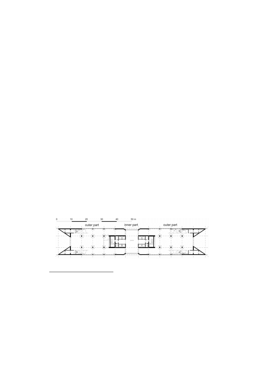
In the analysed building, lateral loads that arise as a result of winds and earthquakes are
resisted by the three-dimensional system of coupled shear walls (see Fig. 1). The static
analysis was carried out on the basis of some variant of the continuous connection method
(Wdowicki and Wdowicka, 1993). In the continuous connection method lintel beams are
treated as the equivalent shear connection medium between shear walls, while the walls are
simply regarded as vertical cantilevers. The technique may be used for both plane and spatial
structures, which are essentially regular in form throughout the height.
Fig. 1. Floor layout of the South Gate
1
Assistant Professor, Institute of Structural Engineering, Poznan University of Technology,
Poland

For the dynamic analysis it is convenient to use a hybrid approach based on the
analysis of an equivalent continuous medium and a discrete lumped mass system (Aksogan
et al., 2003, Li and Choo, 1996, Wdowicki et al., 1995). A dynamic model with masses in the
form of rigid floor slabs has been adopted since over a half of building total mass is
concentrated on the floor levels. For shear wall multi-storey structure it is more natural to
determine the flexibility matrix D than stiffness matrix K. The vibration of a structure is
described by the following relation :
F
D
x
x
C
D
x
M
D
=
+
+
&
&
&
(1)
where D, M and C are the flexibility, mass and damping matrices, respectively; x is d-
element vector of generalised coordinates; d is the number of dynamic degrees of freedom
of the analysed structure; and F is d-element vector of generalised excitation forces. The
flexibility matrix D is generated from the exact solution of the governing differential
equation for 3D continuous model. Also mass matrix is generated exactly according to real
distribution of walls, connecting beams and floor slabs and including flexural and torsional
inertia.
The seismic response of the structure is estimated using the response spectrum
technique. The involved steps are as follows:
•
determination of natural frequencies and mode shapes
•
evaluation of modal participation factors and calculation of modal loading on the
structure (using an appropriate design spectrum)
•
determination of response estimate taking into account the contribution from the given
number of modes for various parameters of interest .
3. Results of the seismic analysis
As a result of the first calculation step by DAMB, periods and corresponding mode
shapes have been received. The periods of the first 6 modes for the outer part of the building
are summarized in Tab. 1.
Tab. 1. Natural periods of the left part of the building
Mode number
Natural period [s]
Dominant direction
1
3.56536
first mode N-S
2
3.15713
first mode E-W
3
1.54929
first torsional mode
4
0.69140
second mode N-S
5
0. 50211
second mode E-W
6
0.35925
second torsional mode
In the analysed case frequencies of two first translational modes are closely spaced.
When the modal responses for different modes are coupled, according to Eurocode 8 more
accurate procedure than SRSS method for the combination of the modal maxima will be
adopted. Our previous analysis serves as the basis of choosing the CQC method (Wilson
et
al.
,
1981).
The analysis was based on damage limitation state, according to Eurocode 8 (PrEN
1998-1:200X, 2003). The requirement of damage limitation for buildings having non-
structural elements of brittle materials attached to the structure is accomplished by Eurocode
8, when interstorey drifts do not exceed values:
h
d
r
005
.
0
≤
ν
where
h
is the storey height;
v
is the reduction factor to take into account the lower
return period of the seismic event associated with the serviceability limit state; and
d
r
is the
design interstorey drift, evaluated as the difference of the average lateral displacements at the
top and bottom of the storey under consideration and calculated according to 4.3.4 from
Eurocode 8 .
For the analysed building the importance category II according to Eurocode 8 may be
assumed, for which the reduction factor
ν
= 0.4. Assuming that specific provisions for all
structural elements shall be satisfied to provide the appropriate amount of ductility (see 5.4 –
5.6 of PrEN 1998-1:200X, 2003), the ductility class DCM (medium ductility) has been
established. The corresponding value of behaviour factor
q
= 3.3 has been applied. In effect
the following limit of maximum interstorey drift index has been obtained:
%
379
.
0
4
.
0
3
.
3
005
.
0
0.005
=
⋅
=
⋅
≤
∆
ν
d
e
q
h
d
where
∆
d
e
is the difference of lateral displacements at the top and bottom of the storey,
determined by a linear analysis based on the design response spectrum.
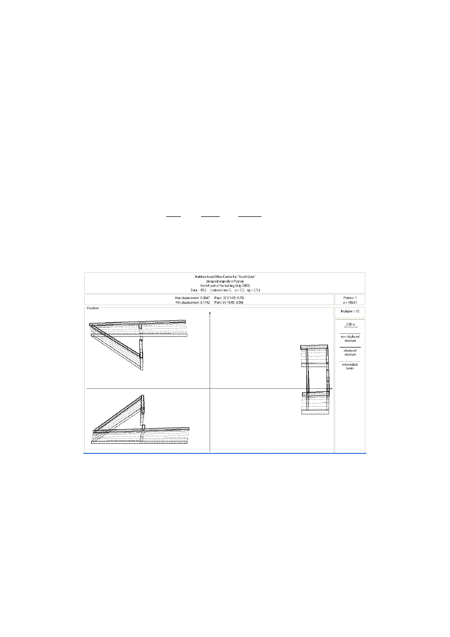
Fig. 2. Horizontal displacements of shear wall structure
in the left part of the building

In the analysis the design spectrum for elastic analysis according to Eurocode 8 has
been taken. The type 1 spectrum and subsoil class C (S = 1.15, T
B
= 0.2, T
C
= 0.6, T
D
= 2.0)
have been considered. The value of viscous damping ratio
ξ
= 5% has been assumed.
The analysis has been carried out for the design ground acceleration a
g
= 2.5 m/s
2
and
seismic wave direction parallel to Y-axis (N-S). The results of the analysis carried out on the
left outer part of the building, based on the response spectrum technique, are shown in
Fig. 2.The obtained maximum value of interstorey drift was equal to 0.361 % < 0.379 % .
4. Conclusions
In this study the seismic analysis of shear wall tall building has been carried out using a
continuous-discrete approach and the response spectrum technique. The results of the
analysis indicate that the analysed building having sufficient stiffness against lateral loads
arising from wind, meets requirements of Eurocode 8 in damage limitation state for values of
design ground acceleration less than 2.5 m/s
2
.
References
AKSOGAN O., ARSLAN H.M., CHOO B.S., Forced vibration analysis of stiffened
coupled shear walls using continuous connection method. Engineering Structures,
2003, Vol.25, no.4, pp. 499-506.
LI G.-Q., CHOO B.S., A continuous-discrete approach to the free vibration analysis of
stiffened pierced walls on flexible foundations. Int. J. Solids and Structures, 1996,
Vol.33, no.2, pp. 249-263.
PrEN 1998-1:200X: Eurocode 8: Design of structures for earthquake resistance. Part 1:
General rules, seismic actions and rules for buildings. DRAFT No 6. Version for
translation (Stage 49). January 2003. CEN, Bruxelles.
WDOWICKI J., WDOWICKA E., System of programs for analysis of three-dimensional
shear wall structures. The Structural Design of Tall Buildings, 1993, Vol.2, no.4,
pp. 295- 305.
WDOWICKI J., WDOWICKA E., BŁASZCZY
Ń
SKI T., Integrated system for analysis of
shear wall tall buildings. In: Proc. of the Fifth World Congress "Habitat and High-
Rise: Tradition and Innovation". Council on Tall Buildings and Urban Habitat,
Amsterdam, pp. 1309-1324, 1995.
WILSON E.L., DER KIUREGHIAN A., BAYO E.P., A replacement for the SRSS method
in seismic analysis. Earth. Eng. & Struct. Dyn., 1981, Vol.9, pp. 187-194.
Summary
The tallest building designed in Pozna
ń
(western part of Poland) is the case study. The
analysed building is a multifunctional office centre with the heliport on the top, called the
“South Gate”. The main structure is the RC slab and column system with shear walls and
cores. After many static analyses the seismic analysis, based on damage limitation state
according to Eurocode 8, was made. The analysis, in which a continuous-discrete approach
and the response spectrum technique were applied, was carried out by means of DAMB
program as part of an Integrated System. The allowable design ground acceleration was
evaluated.
Wyszukiwarka
Podobne podstrony:
Multistage evolution of the gra Nieznany
16 Changes in sea surface temperature of the South Baltic Sea (1854 2005)
Ecology and behaviour of the tarantulas
A Behavioral Genetic Study of the Overlap Between Personality and Parenting
African Filmmaking North and South of the Sahara
51 721 736 Evaluation of the Cyclic Behaviour During High Temperature Fatique of Hot Works
Endoscopic investigation of the Nieznany
Integration of the blaupunkt RC Nieznany
On the Atrophy of Moral Reasoni Nieznany
Biogenesis of the gram negative Nieznany
asm state of the art 2004 id 70 Nieznany (2)
U S Scourge Spreads South of the Border
An analysis of the European low Nieznany
A History of the Evolution of E Nieznany (2)
MEPC 154(55) Designation of the Southern South African waters as a Special Area
Evolution of the Microstructure of Dynamically Loaded Materials
więcej podobnych podstron