
Combustion, Explosion, and Shock Waves, Vol. 38, No. 2, pp. 239–247, 2002
Evolution of the Microstructure of Dynamically Loaded Materials
UDC 539.3 + 621.7.044.2
M. P. Bondar’
1
Translated from Fizika Goreniya i Vzryva, Vol. 38, No. 2, pp. 125–134, March–April, 2002.
Original article submitted April 24, 2001.
The paper deals with the evolution of the microstructure in materials after explosive
loading by the method of a hollow thick-walled cylinder. The materials considered
differ in the type of crystal lattice and initial state (grain size and initial defect
density).
The role of crystal structure in the formation of the microstructure of
single crystals and coarse-grain copper specimens formed under explosive deformation
is investigated. The microstructures formed are compared with the corresponding
strains. It is shown that during high-rate deformation, fragmentation of the structural
elements occurs at all scale levels. The fragmentation mechanism and the associated
properties depend on the initial structure and state of the material.
The special
features of the microstructure evolution in materials revealed in this work are taken
into account in producing new materials by dynamic and quasidynamic methods.
INTRODUCTION
Special features of the microstructure evolution
with increase in strain under static loading are described
in [1–3]. The formation of structures during deforma-
tion depends on the type of dissipative processes. Being
an energy-nonequilibrium system, a body is deformed
in such a manner that the most effective channels for
energy dissipation are activated. The degree and mech-
anism of the dissipative processes and the formation of
dissipative structures depend on the initial structure of
the materials being deformed. Special features of the
microstructure evolution under increasing strain and
dynamic loading have not been studied systematically,
in particular, because of the variety of the experimen-
tal conditions, which makes it difficult to identify the
results obtained. Extensive studies in this field are of
considerable importance for both developing the theory
of plastic strain and designing new materials by quasi-
dynamic and dynamic methods.
In this work, we studied the microstructure evolu-
tion and the critical parameters of unstable plastic flow
(ε
r
) in materials with different types of crystal lattice
and different initial states (grain size and initial defect
density) after explosive loading by the method of hollow
1
Lavrent’ev Institute of Hydrodynamics, Siberian Division,
Russian Academy of Sciences, Novosibirsk 630090;
bond@hydro.nsc.ru.
thick-walled cylinder [4]. Transformation of the struc-
ture formed under increasing strain is analyzed with the
use of the experimental results obtained in this work and
those published previously [4–8].
1. THE EFFECT OF CRYSTAL STRUCTURE
AND INITIAL STATE OF A MATERIAL ON
THE STRUCTURE EVOLUTION UNDER
DEFORMATION BY EXPLOSIVE
LOADING USING THE METHOD OF
HOLLOW THICK-WALLED CYLINDER
To study the formation of a structure under high-
rate deformation, we used materials with different crys-
tal lattices: Cu with a face-centered cubic lattice (FCC),
Ta with a body-centered cubic lattice (BCC), and Ti
with a hexagonal close-packed lattice (HCP). The ini-
tial structures of the materials differed in defect density
and grain size d (single crystal of Cu and polycrystal
structures with d = 1000 and 30 µm for Cu, d = 60
and 40 µm for Ta, and d = 140 and 25 µm for Ti).
High defect density was produced by plane-wave
shock loading [6].
A distinguishing characteristic of
this loading is that it leads to high density of randomly
distributed defects, mostly dislocations, with residual
strain lower than 5%.
High-rate deformation by ex-
plosive collapse of a hollow thick-walled cylinder [4] al-
0010-5082/02/3802-0239 $27.00 c
2002
Plenum Publishing Corporation
239
240
Bondar’
TABLE 1
Material
d, µm
State
ε
r
1000
Unhardened
0.26–0.30
Hardened
0.6–0.7
Cu
30
Unhardened
>2
Hardened
—
Ta
60
Unhardened
1.2
Hardened
1.01
40
Unhardened
>1.5
Hardened
—
Ti
140
Unhardened
0.59
Hardened
0.3
25
Unhardened
0.22–0.26
Hardened
<0.17
lowed us to compare strains with the corresponding mi-
crostructures formed over a wide range of strains.
A common feature of all the collapsed materials is
that collapse of the cylindrical cavity is accompanied
by localization of the strain, which degenerates into a
system of cracks near the central part of the specimen
[4–9]. The strain ε
r
attained before the onset of local-
ized plastic flow are listed in Table 1 for the materials
considered.
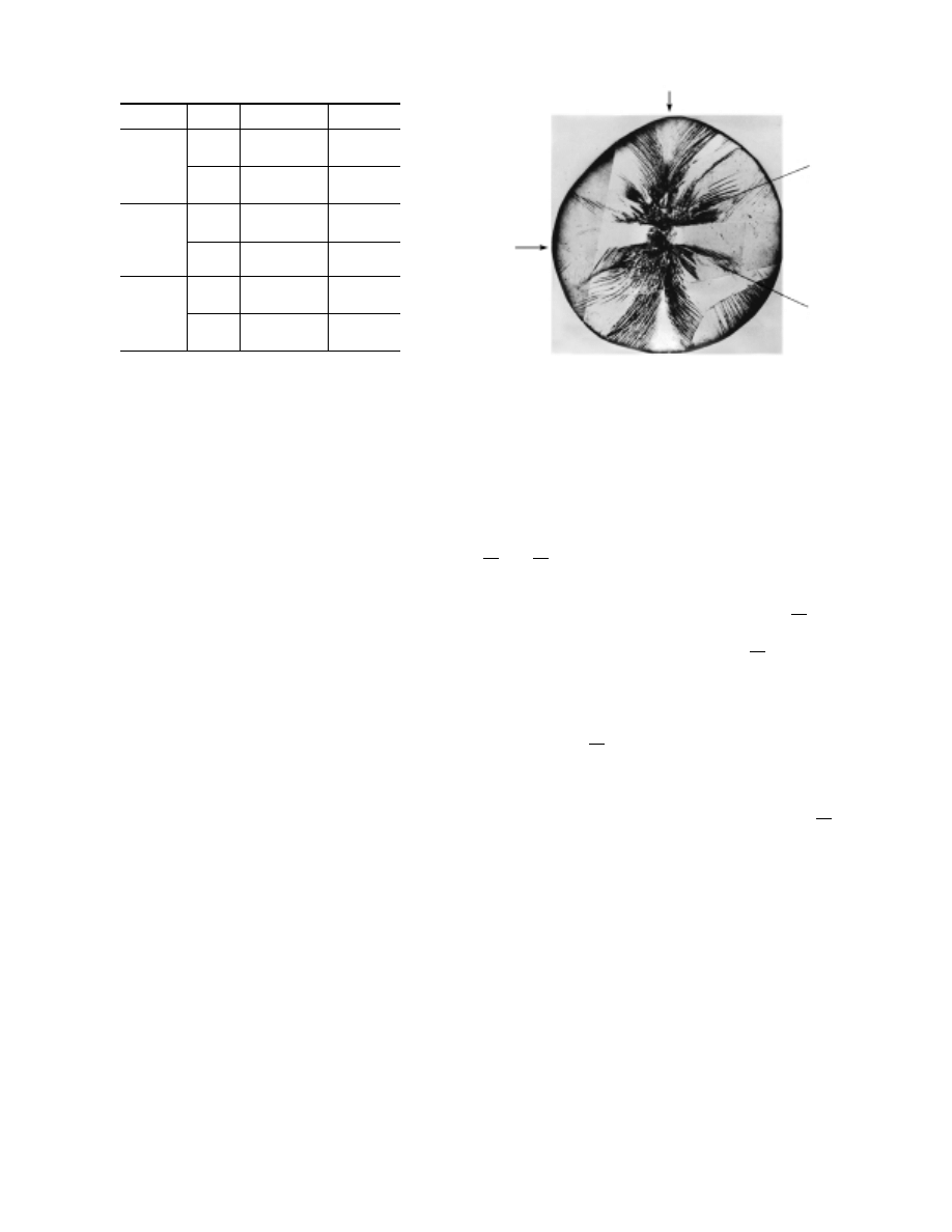
In these experiments, copper single crystals shaped
like tubes of inner diameter 11 mm and wall thickness
3 mm were subjected to collapse. The single crystal
was oriented in such a manner that the axis of the tube
(cylinder) was directed along the [134] crystallographic
direction. Figure 1 shows shear bands in the metallo-
graphic section that coincides with the (134) crystal-
lographic plane. The distinct symmetry of the shear
bands is seen. Some of the bands reach the outer sur-
face of the crystal, and there are bands whose origin is
located within the surface of the metallographic section
or near the cavity center. In addition, there is a sector
in which localized shear bands are absent.
It is known that in static tests, shear occurs over
close-packed slip systems, i.e., planes and correspond-
ing directions in these planes. For FCC copper, these
systems are planes of the type (111) and directions of
the type
{110}. In this case, the priority in the activ-
ity of the slip systems depends on the reduced shear
stress τ determined by the Schmid factor m, which is
equal to the product of the sine of the angle between the
loading direction and the close-packed plane into the
cosine of the angle between the loading direction and
the close-packed slip direction lying in this plane. For
the maximum reduced stress (τ
max
), m is equal to 0.5.
In Fig. 1, one can see traces of almost all close-packed
slip systems, which is a result of axisymmetric loading.
4
1
2
3
Fig. 1. Microstructure of collapsed single-crystal
specimens (
×50).
In the case of explosive loading, where stresses exceed
the value of τ
max
, the activity of slip systems depends
weakly on m. Whether slip traces are present or absent
in the plane of a metallographic section depends on the
angle they make with the (134) plane. The center of
the section is the point of intersection of the directions
[128¯
3], [2443], and [62¯
3], which are the medians of the
(134) plane and coincide with the direction of the radial
load for collapse of the cylinder. The minimum angle
equal to 16
◦
is made by intersection of the [128¯
3] di-
rection — cylinder radius (position 1 in Fig. 1) — with
the close-packed direction [¯
110]. The [128¯
3] direction
is close to the [110] angle of the stereographic triangle
and determines multiple slippage. For close-packed slip
systems (1¯
11) [¯
101] and (¯
111) [101], the Schmid factor
reaches maximum values (0.39 and 0.48, respectively)
relative to the [128¯
3] direction and the corresponding
planes make minimum angles (25
◦
and 48
◦
) with the
(134) section. For these reasons, the traces of the slip
systems belonging to the (1¯
11) and (¯
111) appear as two
families of bands directed at different angles to [128¯
3]
(position 1 in Fig. 1) with their origin located on the pe-
riphery of the single crystal. The other shear bands refer
to the directions of slip systems relative to the loading
directions that determine single slip. In the metallo-
graphic section, they are located at different distances
from the center and are easily identified in accordance
with the crystallographic orientation of the single crys-
tal. One can see from Fig. 1 that the density of the
shear bands increases toward the center, which is deter-
mined by the geometry of loading. As the shear bands
merge, their width increases and they become cracks.
There is a sector (4) in which shear bands are absent in
the metallographic section. The location of shear bands
Evolution of the Microstructure of Dynamically Loaded Materials
241
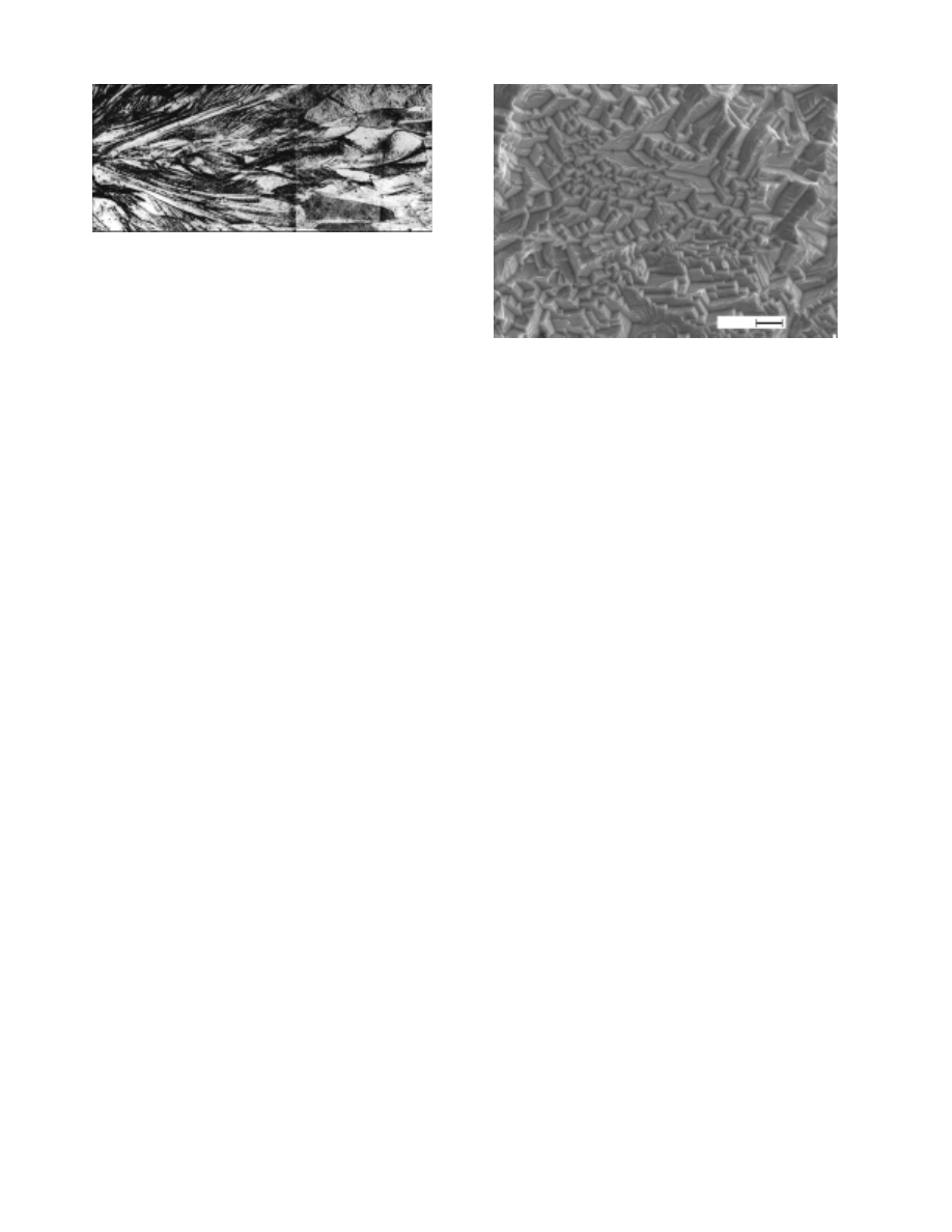
Fig. 2. Shear macroband in the collapsed specimen
from coarse-grain copper (
×50).
in the adjacent regions (2 and 3) determines the rigid-
body motion of the sector toward the center, which is
seen in Fig 1.
Thus, the single crystal is fragmented by shear
bands, which develop in close-packed systems according
to the crystallographic orientation of the single crystal
relative to the direction of applied stresses. Near the
cavity of the collapsed specimen there are narrow re-
gions of the recrystallized structure. These regions are
arranged irregularly in accordance with the inhomoge-
neous shear-band pattern.
In coarse-grain copper specimens (d = 1000 µm),
localized shear bands appear at different distances from
the center of the collapse; in some grains they appear
in regions where ε
r
∼
= 0.26 (Fig. 2). As the strain in-
creases, localization bands appear in other grains. This
is responsible for the saw-tooth boundary of the begin-
ning of development of shear strains relative to the cen-
ter of collapse. Harren et al. [3] determined ε
r
for single
crystals of an Al–0.5% Cu alloy of various orientations
subjected to plane static compression: ε
r
= 0.26–0.95.
The values of ε
r
obtained in our tests on coarse-grain
copper are in the indicated range.
Shear bands are
formed in individual grains with different values of ε
r
,
which is explained by their orientation relative to the
plane of the metallographic section. This was shown
above in considering the formation of a microstructure
in a single crystal. The beginning of the macroband
depends on the extent to which neighboring grains are
disoriented with respect to one another and to the radial
load. As the strain increases, the macrobands formed in
coarse-grain specimens propagate along a slightly bro-
ken line toward the center of the collapse. During prop-
agation, the macrobands are deflected from the radial
direction, and in some places they leave the plane of
metallographic section (see Fig. 2).
In collapsed specimens of fine-grain copper (d =
30 µm), no localized plastic strain bands were de-
tected [4]. Near the central cavity there is a recrys-
tallized microcrystal structure indented by thin radial
cracks.
The transformation of the microstructure in
copper with variation in grain size indicates that in the
3
µ
m
Fig. 3. Intragranular block structure in collapsed
fine-grain copper specimens.
ranges ε ∼
= 0.1–3 and ˙
ε ∼
= 10
4
–10
5
sec
−1
, the formation
of the microstructure is determined mainly by the rela-
tionship between the processes occurring at the micro-
and mesolevels. Observation of the microstructure on
a scanning electron microscope shows that the defor-
mation is uniform within each grain of the collapsed
fine-grain specimen. Each grain is divided into blocks
of size ∼
= 1 µm (Fig. 3). The change in the orientation of
the block structure from grain to grain is compensated
for by intermediate adjustment of conjugate blocks, as
can be seen from Fig. 3 (three grains are shown). The
highly homogeneous block structure in each grain with
a small scatter in the size and direction of the blocks
and compensated transition into adjacent grains indi-
cate that the plastic flow is stable. Resistance to rota-
tions at the grain contacts leads to heat release, which
favors dynamic recrystallization. The latter is respon-
sible for a decrease in the average grain size from 30 to
22 µm in the region of 0.3 < ε < 0.7. Near the cavity
surface, where deformation is most severe (ε > 0.7 and
˙
ε increases), the grains are extended toward the cen-
ter [4]. This shows that as the strain rate increases (and
hence, the duration of the process decreases), a grain of
size 30 µm can no longer be a structural element that
implements the rotational mode of deformation. Un-
der these conditions, texturing proceeds actively. This
is supported by the results obtained in [5], where it is
shown that during explosive welding of internally oxi-
dized copper plates with a fine-grain structure (30 µm),
a strong melt-free bond is formed at the contact sur-
face for high velocity of the contact point under col-
lision (>1.5
· 10
7
sec
−1
). The velocity of the contact
point depends directly on the strain rate at the contact
boundary. The bond is formed owing to the developed
compatible strain for spreading grains. During welding
of plates with a coarse-grain structure, no strong bonds
242
Bondar’
TABLE 2
Action
r, mm
(∆a/a)
· 10
3
D, µm
r, mm
(∆a/a)
· 10
3
D, µm
Copper
Tantalum
Shock-wave
—
1.42
—
—
0.94
—
loading
Shock-wave
1–3
0.95
0.11
1–3
0.94
0.11
loading and collapse
>5
0.35–0.6
0.15–0.18
>5
0.75
0.15
Collapse without
1–3
0.7
0.2
1–3
0.11
—
preloading
>5
0.3–0.6
0.22
>5
0.11–0.15
Notes. r is the distance from the center of the cylinder, (∆a/a)
· 10
3
is the variation in the lattice
parameter, and D is the size of the blocks.
are formed under these conditions because of the early
development of localized-shear bands accompanied by
melts and cracking on the contact boundaries.
In materials with 30-µm grains, the absence of in-
stability of plastic flow can be explained by the fact that
for the loading parameters used, a grain of size 30 µm
itself is the structural element that implements the ro-
tational mode of deformation.
The presence of localization bands in coarse-grain
copper for ε
r
= 0.26 is evidence of translation instability
at the microlevel.
In collapsed BCC-tantalum specimens with a grain
of size 60 µm at ε
r
= 0.65, closely spaced shear-strain
bands are observed in some grains [6]. The deformation
proceeds in such a manner that in some grains, slip
bands make up a grid to form mesovolumes consisting
of several grains. The initial direction of the grid sides
coincides with the direction of maximum shear strains.
As the strain increases, the grid sides become closer
to each other and the mesovolumes are distorted. For
ε
r
= 1.2, the bands developed in separate grains merge
into macrobands, which radiate through many grains
toward the center; for ε = 2, the macrobands become a
system of cracks.
In collapsed specimens with grains of size 45 µm,
neither a structure developed at the mesolevel nor mac-
robands of strain localization [6] were detected; as in the
case of fine-grain copper, a system of cracks is formed
in the neighborhood of the central cavity.
Fragmentation of the structure in copper and
tantalum becomes more pronounced after preliminary
shock-wave loading, which increases the defect density.
The defect structure formed by shock-wave loading de-
termines the conditions under which an intragranular
block structure is formed under subsequent plastic de-
formation. The block structure developed ensures uni-
form deformation in prehardened specimens to rela-
tively large strains [7]. The formation of block structure
in these materials (see Fig. 3), was supported by studies
of changes in the residual microstrain of the crystal lat-
tice and in the dispersity of the intragranular structure
after all types of loading by analyzing x-ray diffraction
line broadening. The results are given in Table 2.
Microstrains are determined by randomly dis-
tributed defects of the crystal lattice, and the dispersity
of the block structure characterizes the number of sub-
boundaries which are sufficiently disoriented that neigh-
boring regions of the crystal participate incoherently in
the dissipation.
Preliminary loading, which led to the development
of the substructure during the subsequent collapse, is
responsible for delay of strain localization to large val-
ues of ε
r
in both coarse- and fine-grain specimens (see
Table 1).
The special features of formation of the structure
in titanium with an HCP lattice differ markedly from
those established for FCC copper and BCC tantalum. A
characteristic feature of titanium is that localized shear-
strain bands are adiabatic-shear bands [8]. In coarse-
grain titanium, these bands are formed for ε
r
= 0.59;
in fine-grain titanium, they are formed for ε
r
= 0.22
(see Table 1) [8, 9].
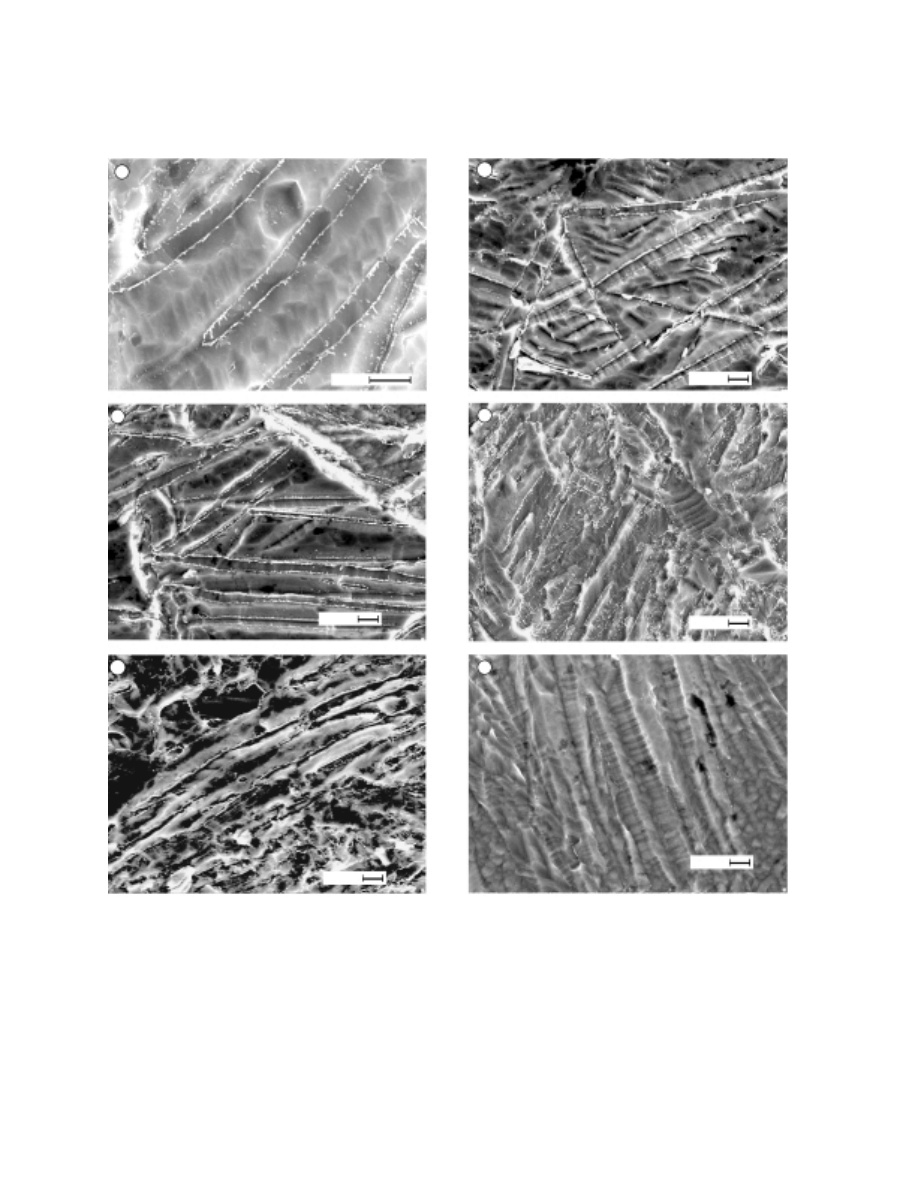
Figure 4 shows the microstruc-
ture evolution in coarse-grain titanium with increase in
strain, which is manifested in an increase in the twin-
ning density. Fragmentation, which occurs mainly by
twinning, does not determine uniform deformation at
the microlevel.
In collapsed pre-hardened specimens
of coarse-grain and fine-grain titanium, adiabatic-shear
bands are formed for ε
r
= 0.3 and ε
r
< 0.17, respec-
tively.
Thus, the value of ε
r
decreases as the degree of
imperfection in the structure of titanium increases due
to a decrease in grain size and due to the density of the
defects formed by preliminary shock-wave loading.
Evolution of the Microstructure of Dynamically Loaded Materials
243
a
b
c
d
e
f
2
µ
m
2
µ
m
2
µ
m
2
µ
m
2
µ
m
2
µ
m
Fig. 4. Change of the twinning microstructure in collapsed specimens of coarse-grain titanium versus strain:
ε = 0.17 (a), 0.18 (b), 0.19 (c), 0.5 (d), 0.59 (e), and >0.59 (f) (microstructure between adiabatic-shear bands
with microcracks).
244
Bondar’
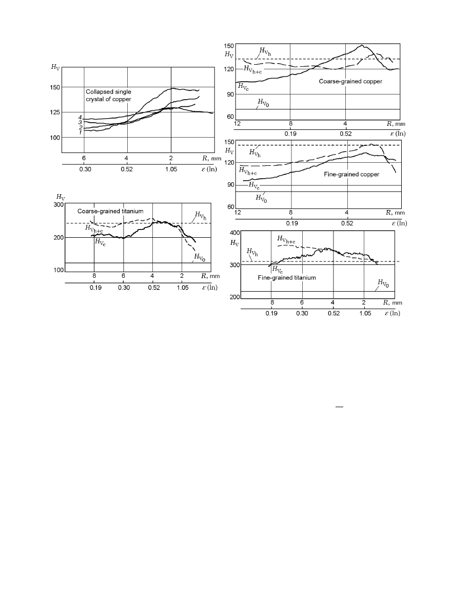
Fig. 5. Microhardness versus strain along the radii of collapsed cylinders, for single crystal: curves 1–4 refer to the
positions 1–4 shown in Fig. 1; for polycrystalline copper and titanium, curves H
V
0
, H
V
h
, H
V
c
, and H
V
h+c
refer to
the microhardnesses of the initial, prehardened, collapsed, and collapsed prehardened specimens, respectively.
The evolution of the deformation microstructure
with increase in strain is traced by variation of the mi-
crohardness H
V
along the radius of collapsed specimens.
The microhardness is measured along a broken line in
such a manner that the projections of the prints onto
the radius close up with one another. Figure 5 shows
the dependence of microhardness on strain for coarse-
and fine-grain titanium subjected to different actions.
For comparison, curves of H
V
(ε) for copper specimens
are also shown in Fig. 5.
Of interest are also the curves of variation of mi-
crohardness along the radii of collapsed single-crystal
specimens that refer to regions with the characteristic
pattern of shear bands.
It is clear that for a single
crystal, the shape of the curves H
V
(ε) is determined
by the special features of strain variation in different
positions of the cross section (Fig. 1): position 4 dif-
fers from position 1 in that it refers to a sector without
shear bands, the microhardness varies slightly with in-
crease in strain, and the region of position 4 moves as
a rigid body toward the center.
The motion of this
position is determined by the location of shear bands
in adjacent regions. The region of position 1 refers to
the neighborhood of radius [128¯
3], where deceleration
is caused by counter shears. In this region, the curve
of H
V
(ε) is similar to the curve of σ(ε) [10] and it is of
a multistage nature typical of single crystals. Curves 2
and 3 refer to the regions located between positions 1
and 4.
For titanium, curves of H
V
(ε) (see Fig. 5) show that
each loading stage contributes to hardening. Curves of
variation of microhardness for specimens that collapsed
after prehardening (H
V
h+c
) show relaxation structures
most clearly. In the deformation of coarse-grain tita-
nium, the quantity H
V
h+c
initially decreases somewhat
relative to the microhardness of pre-hardened specimen
Evolution of the Microstructure of Dynamically Loaded Materials
245
H
V
h
owing to the beginning of intense twinning [9],
which produces relaxation structures. After the limiting
density of twins is attained for ε = 0.3, and with further
increase in strain, the values of H
V
h+c
exceed H
V
h
. For
specimens of fine-grain titanium, H
V
h+c
> H
V
h
over the
entire range of ε.
For copper specimens, the relationship between
H
V
h+c
and H
V
h
is different [4]: curves of H
V
h+c
are
lower than curves of H
V
h
(see Fig. 5) for all values of ε.
This is most pronounced for fine-grain copper.
For high-rate deformation, the degree of harden-
ing [increase in H
V
(ε)] and the values of parameters
for which the plastic flow becomes unstable (ε
r
) are
determined by the character of the corresponding dis-
sipative processes. Dissipative (relaxation) structures
are formed by a mechanism such that the internal en-
ergy of the material tested is minimized and the degree
of hardening is the higher the harder the development
of irreversible changes in the structure that decrease
the internal energy of the system.
These structural
changes occur in titanium when an additional defor-
mation mechanism (twinning) begins to work, which is
illustrated by the example of structural transformation
in coarse-grain titanium (see Fig. 4).
After shock-wave loading, the state of the mate-
rial is characterized by a high density of randomly dis-
tributed defects and high energy; therefore, this state
is unstable. The nature of relaxation processes in cop-
per and tantalum is determined by their crystal struc-
ture, responsible for defect mobility. Under subsequent
high-rate plastic deformation, defects are redistributed
in copper and tantalum, i.e., low-energy dislocation
(block) structures are formed. As a result, intragran-
ular fragmentation of the structure occurs, which shifts
the critical instability parameters of plastic flow toward
the region of larger strains and leads to softening of the
material.
It should be noted that the structure fragmentation
in titanium due to twinning does not create conditions
for preservation of the uniform plastic flow up to large
values of ε and does not lead to substantial softening
and increase in internal energy. In contrast to the dis-
sipative structures formed in copper, twins are not the
structural elements capable of activating the rotational
component of deformation.
Thus, in strained materials with FCC and BCC
lattices, relaxation processes are accompanied by for-
mation of dissipative structures (strain carriers). The
high initial defect density (dislocations and small grain
size) favors the formation of microstructures that en-
sure uniform deformation up to large values of ε. These
results were taken into account in designing a material
by the quasidynamic method.
2. PRODUCING A STRONG
MICROCRYSTALLINE MATERIAL
BY THE QUASIDYNAMIC METHOD
It was shown above that during high-rate severe
plastic deformation, fragmentation of the structure oc-
curs most actively in FCC materials with highly imper-
fect initial structure upon reaching values ε = 0.3–0.7.
We used these results to produce a material from chips
of internally oxidized Cu–0.4% Al alloy based on FCC
copper. The structure of internally oxidized copper al-
loys is highly stable [11], which ensures high strength of
this material up to temperatures of 800
◦
C.
Chips of the internally oxidized alloy 150 µm thick
were pressed at room temperature to produce a briquet
with open porosity. The final material having the shape
of bars was obtained by double punching.
The first
punching was performed at T = 1000
◦
C and ε = 0.5,
and the second punching was performed at T = 20
◦
C
and ε = 0.4. In both cases, the strain rate was 0.5 sec
−1
(quasidynamic regime) and the values of ε lied in the
interval of strains for which the structure fragmentation
was maximal.
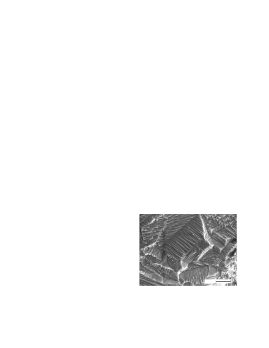
An analysis using a scanning electron microscope
shows that the microstructural elements are frag-
mented. After the first punching, micrograins were of
size 1–10 µm. In Fig. 6, they have different deformation-
shear orientation.
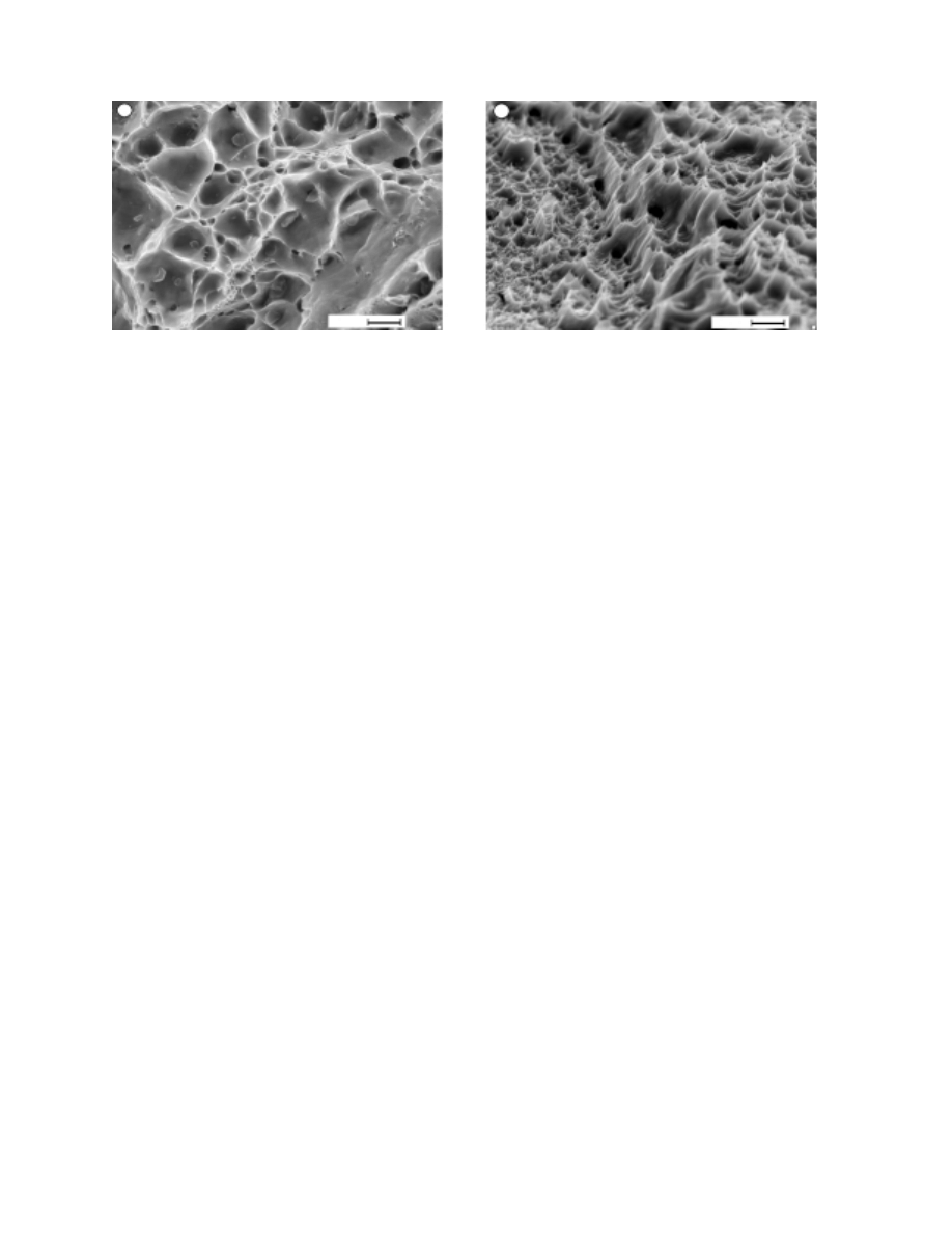
Figure 7 shows the fracture structure after the first
and second punching.
An analysis of the structures
of the fractured specimens shows that the fracture of
doubly-punched specimens is tougher (Fig. 7b) than
that of single-punched specimens (Fig. 7a). The size of
the fracture cells is determined by the size of the final-
3
µ
m
Fig. 6. Microstructure of a compact of internally ox-
idized copper after the first punching by the quasi-
dynamic method.
246
Bondar’
a
b
1
µ
m
1
µ
m
Fig. 7. Microstructure of fracture of bars produced by the quasidynamic method: (a) first punching; (b) second punching.
structure fragments. One can see from Fig. 7 that after
the second punching, the structure of the specimens be-
comes more dispersed. This is possibly responsible for
the tougher fracture despite the fact that the second
punching was performed at room temperature.
The characteristics of the material show that the
results established for the dynamic loading regime
are applicable to the pressing (quasidynamic) loading
regime.
Along with heat-resistant materials, internally oxi-
dized copper obtained by double punching was tested
as inserts in nozzles of a wind tunnel [12].
Prelim-
inary studies show that internally oxidized copper is
promising for operation under severe cyclic temper-
ature and force conditions (T = 1300–1600 K and
p
0
= 600–750 MPa) [12].
CONCLUSIONS
An analysis of the shear-band pattern in the cross
section of collapsed single crystals shows that under ex-
plosive deformation, shear bands develop in the same
succession under static loading. They first develop in
the close-packed slip systems in accordance with the
crystallographic symmetry of the single crystal. This
fact determines the above-established interval of critical
strains for occurrence of localized strains in coarse-grain
specimens.
During
high-rate
deformation,
the
following
changes occur in the microstructure: increase in disloca-
tion density, formation of dissipative structures (cellular
structure, twins, and micrograins), and fragmentation
at all scale levels.
The mechanism of structure fragmentation and the
properties during subsequent deformation are deter-
mined by the nature and initial state of the material:
the degree of development of the subgrain microstruc-
ture in FCC and BCC metals, determined by rearrange-
ment of the dislocation structure, ensures uniform plas-
tic flow up to large values of ε
r
, and the structure frag-
mentation in HCP titanium by the twinning mechanism
leads to a decrease in ε
r
.
The special features of microstructure evolution in
materials are taken into account in designing new ma-
terials by dynamic and quasidynamic methods.
The
structure and properties of the material obtained from
internally oxidized copper of fine fraction (150 µm)
by multiple punching in a hummer mode ( ˙
ε
=
10 sec
−1
refers to quasidynamic mode) are studied. The
properties of the specimens obtained under pulsed high-
temperature and force cyclic loads show that the use of
high-rate deformation is promising for the production
of high-strength materials.
REFERENCES
1. A. D. Korotaev, E. F. Dudarev, T. F. Elsukova, et al.,
“Some urgent problems of the physics of plasticity and
strength of single crystals and polycrystals,” Izv. Vyssh.
Uchebn. Zaved., Fiz., No. 8, 5–15 (1998).
2. V. E. Panin, A. D. Korotaev, P. V. Makarov, and V. M.
Kuznetsov, “Physical mesomechanics of materials,” Izv.
Vyssh. Uchebn. Zaved., Fiz., No. 9, 8–36 (1998).
3. S. V. Harren, H. E. Deve, and R. J. Asaro, “Shear band
formation in plane strain compression,” Acta Metall.,
36, No. 9, 2435–2480 (1988).
4. V. F. Nesterenko and M. P. Bondar’, “Localization of
deformation in collapse of a thick walled cylinder,” Com-
bust. Expl. Shock Waves, 30, No. 4, 500–509 (1994).

Evolution of the Microstructure of Dynamically Loaded Materials
247
5. M. P. Bondar’, “Localization of plastic deformation on
contact, determining the formation of a strong joint,”
Combust. Expl. Shock Waves,
31, No. 5, 612–615
(1995).
6. V. F. Nesterenko, M. A. Meyers, C. LaSalvia, et al.,
“Shear localization and recrystallization in high-strain,
high-strain-rate deformation of tantalum,” Mater. Sci.
Eng. A, 229, 23–41 (1997).
7. M. P. Bondar’ and T. S. Teslenko, “Effect of the degree
of defectness of an original material on the deformation
structure formed in explosive collapse of thick-walled
hollow cylinders,” Combust. Expl. Shock Waves,
33,
No. 6, 718–78 (1997).
8. M. P. Bondar’, O. L. Pervukhina, V. F. Nesterenko,
and Ya. L. Luk’yanov, “Development of the titanium
structure in explosive collapse of thick-walled cylinders,”
Combust., Expl., Shock Waves,
34, No. 5, 590–597
(1998).
9. M. P. Bondar’ and O. L. Pervukhina, “Dependence of
the titanium structure formed under high-rate loading
on its initial state,” Combust. Expl. Shock Waves, 36,
No. 2, 261–271 (2000).
10. V. A. Starenchenko and D. V. Lychagin, “Geometrical
effect in hardening and strain localization of FCC single
crystals,” Fiz. Mezomekh., 3, No. 2, 47–54 (2000).
11. M. P. Bondar’, “Stable structure of internally oxidized
copper alloys,” in: Problems of Hydroimpulsive Engi-
neering (collected scientific papers) [in Russian], No. 8,
Inst. of Hydrodynamics, Novosibirsk (1970), pp. 33–42.
12. M. P. Bondar’, E. S. Obodovskii, V. N. Rychkov,
and M. E. Topchiyan, “The behavior of dispersively
strengthened copper under pulsed high-temperature and
cyclic force loading,” Combust. Expl. Shock Waves, 36,
No. 4, 546–548 (2000).
Wyszukiwarka
Podobne podstrony:
Blanchard European Unemployment The Evolution of Facts and Ideas
Multistage evolution of the gra Nieznany
Becker The quantity and quality of life and the evolution of world inequality
Geodynamic evolution of the European Variscan fold belt
Buss The evolution of self esteem
Corballis The Evolution of Language formatted
A History of the Evolution of E Nieznany (2)
Blanchard European Unemployment The Evolution of Facts and Ideas
From Bosnia to Baghdad The Evolution of U S Army Special Forces from 1995 2004
Gabriel & Steele The Evolution of Lisp
Shaman Saiva and Sufi A Study of the Evolution of Malay Magic by R O Winstedt
The Evolution of Design
CSharp Module 1 Overview of the Microsoft NET Platform
The evolution of brain waves in altered states
An Examination of the Evolution of Army and Air Force
Parametric Analysis of the Ignition Conditions of Composite Polymeric Materials in Gas Flows
więcej podobnych podstron