
Technical Report ECE.P54.2004.12
October 1, 2004
INTEGRATION OF THE BLAUPUNKT RC-10 INFRARED
REMOTE CONTROL WITH THE PROJECT54 SYSTEM
By
PRESCOTT B. ATKINSON

1
TABLE OF CONTENTS

2
TABLE OF FIGURES
Figure 1 – Arrangement of the RC-10 infrared remote control and transceiver................. 5
Figure 7 – Attaching the RC-10 transceiver to pin 4 of a DB-25 connector .................... 10
Figure 12 – The configuration dialog for the RC-10 up arrow button.............................. 23

3
ABSTRACT
The Blaupunkt RC-10 infrared remote control is a proprietary device
manufactured by the Blaupunkt Corporation which is used to control various
functionalities of Blaupunkt consumer car stereo units. The RC-10 model remote control
is designed specifically for use with automobiles, and is molded in a way such that the
remote control is attached to the steering wheel, and is ergonomically-appealing to the
driver of the car. The purpose of this project was to integrate this proprietary device into
the Project54 system as to add system functionality to the nine buttons provided by the
RC-10, mostly for use in police cruisers which may either lack or have unfamiliar cruise
control button systems, or as a less expensive alternative to professionally installed
hardware pushbuttons. The RC-10, having a convenient large pushbutton which was
given the functional behavior of a voice recognition activation button, also has eight other
buttons which have been given custom Project54 system functionality through a system
dynamic link library (DLL), and a standalone configuration application.

4
INTRODUCTION
Project54 is a software and hardware system designed to cheaply integrate voice-
operated control, provide for device data acquisition, and centralize the functionality of
after-market police electronics such as radar units, police radios, and police light-bars.
After-market police devices are controlled and monitored through a microcontroller-
based intermediary, which communicates with the Project54 software through the
system’s Intelligent Transportation System Data Bus (IDB), via the common IDB
interface.
The implementation of the Blaupunkt RC-10 steering wheel remote control
(Figure 2) into Project54 occurs in three stages: the modification of microcontroller
software which recognizes unique transistor-to-transistor logic (TTL)-level time codes
provided by the RC-10 infrared transceiver (Figure 3) for each of the nine buttons, a
Project54 DLL which takes action on the one-byte Control Area Network (CAN) packets
transmitted from the IDB interface microcontroller, and a Microsoft Foundation Class
(MFC) C++ program which allows a user to assign a multitude of Project54 functions to
eight of the nine buttons. The ninth button, a large blue “SRC” button of the RC-10
remote control was given the same functionality as the system’s original hardware push-
to-talk (PTT) button, for operation with the driver’s thumb.
5
BLAUPUNKT HARDWARE
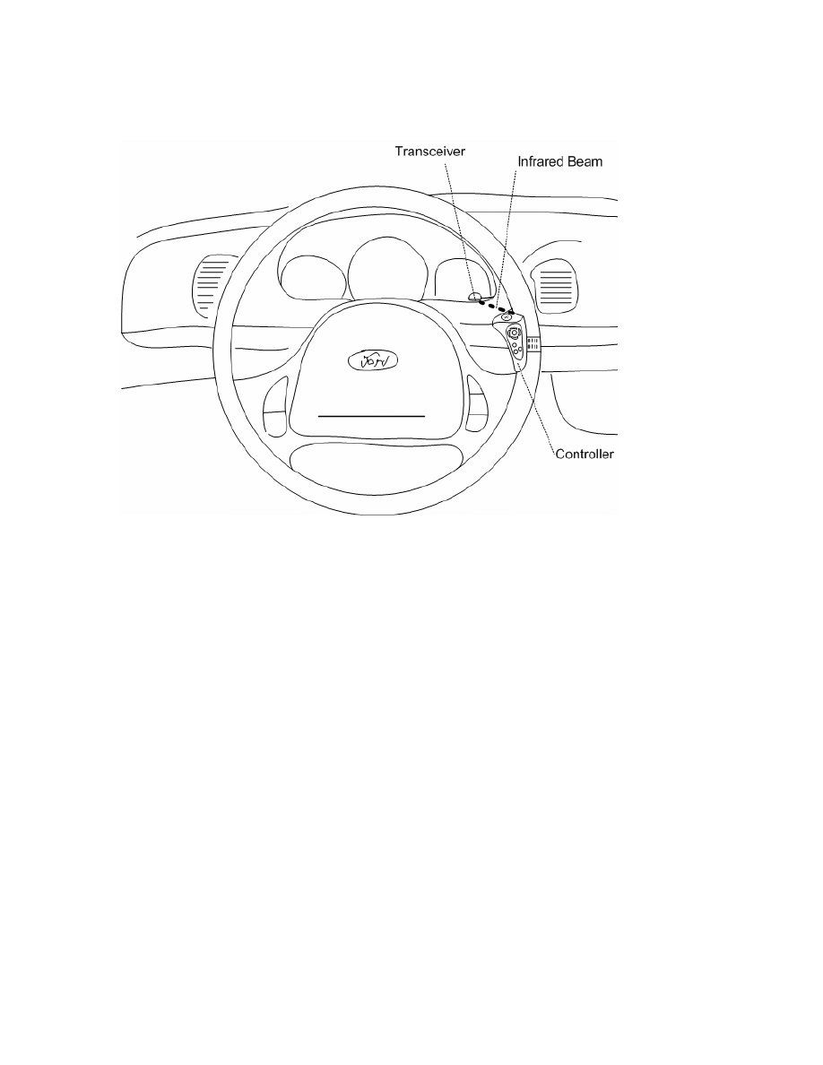
Figure 1 – Arrangement of the RC-10 infrared remote control and transceiver
The RC-10 infrared remote control consists of two pieces of hardware: the remote
control unit which is attached to an automobile steering wheel, and the infrared
transceiver which converts the infrared output signal of the remote control into TTL-level
pulses. When a button on the remote control is pressed, a sequence of pulses is
transmitted to the infrared transceiver. Each of the buttons has a pulse train which has
unique widths associated with it. This pulse train is transmitted approximately every 100
milliseconds while a button is held down on the remote control. The remote control itself
is powered by two 1.5 volt 357-type button cell batteries in series.
6
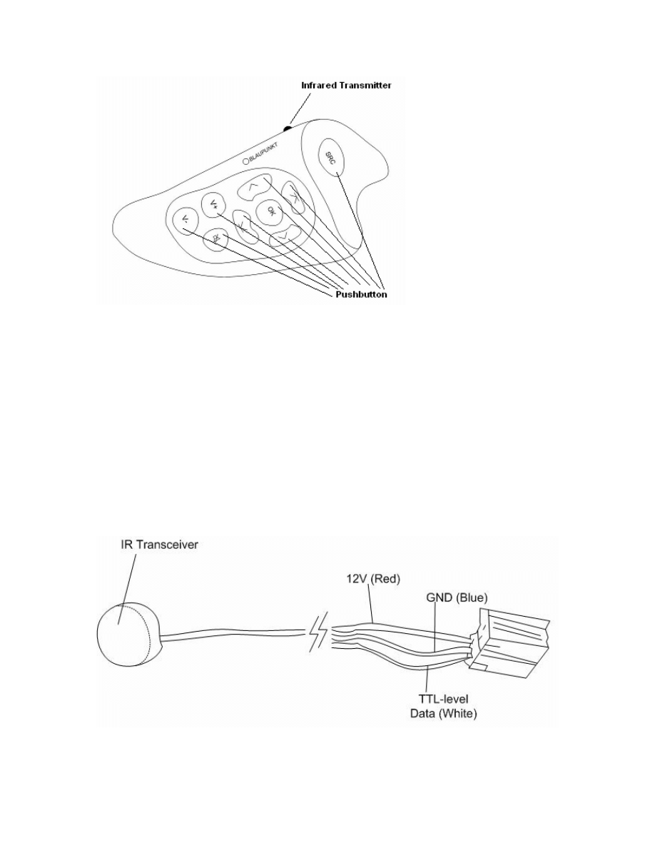
Figure 2 – The RC-10 remote control unit
The infrared transceiver is powered with a +13.8 volt car battery supply, consists
of a photo-detector circuit, and provides a TTL-level output signal which remains in the
logic “high” state of +5 volts when the photo threshold detector is not being stimulated.
The transceiver was designed to be placed on the instrument panel area of an automobile
(Figure 1). A mostly shaded portion of the instrument panel is desirable to avoid
accidental threshold changes.
Figure 3 – The RC-10 infrared transceiver
7
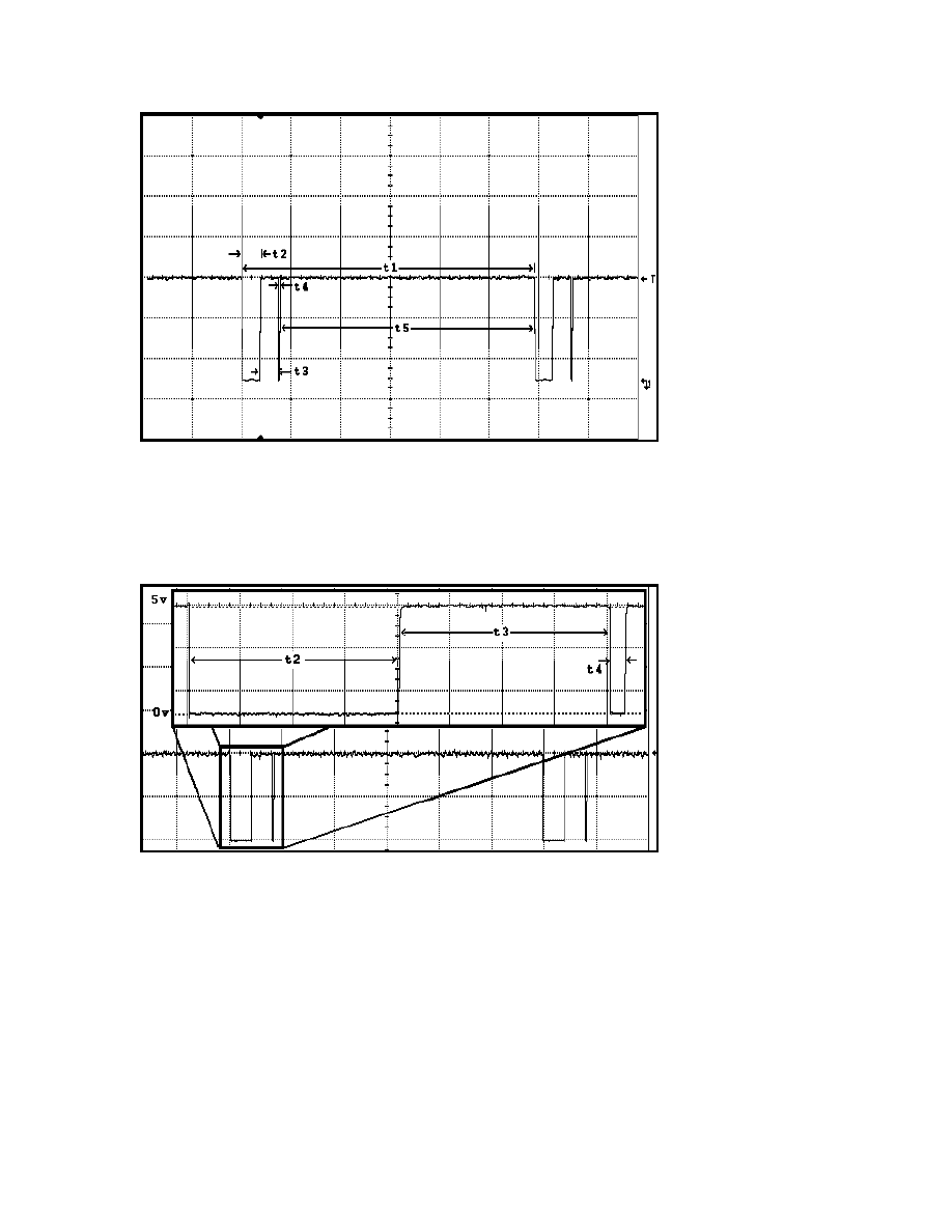
Figure 4 – Pulse train output of the infrared transceiver
Figure 5 – A closer inspection of the transceiver output width pattern
An oscilloscope was attached to the data line of the infrared transceiver, the nine
buttons were activated, and pulse widths were recorded for each of the buttons for the
pattern shown in Figures 4 and 5. Pulses t4 and t5 remained the same width for all nine
buttons. Pulses t2 and t3 were found to be approximately equal in duration for each

8
button. These pulse durations are recorded in Table 1. On the release of any remote
control button, a terminating pulse train is transmitted to the infrared transceiver which is
different in duration than the nine unique pulse trains transmitted by the press of a button.
Button
t1 (ms)
t2 (ms)
t3 (ms)
t4 (ms)
t5 (ms)
SRC(HI/LO) 119.4/117.1 8/6.85
8/6.85
0.625
102.8
OK
118.1 7.42
7.37
0.618
102.7
UP
111 3.81
3.76
0.611
102.8
DOWN
112.2 4.4
4.37
0.634
102.8
LEFT
115.6 6.22
6.15
0.64
102.6
RIGHT
114.4 5.62
5.63
0.633
102.5
VOL UP
108.4 2.58
2.55
0.632
102.6
VOL DN
109.6 3.21
3.16
0.643
102.6
MUTE
113.4 5
4.96
0.6
102.8
Table 1 - Sample receiver pulse times for the 9 remote control buttons
9
MICROCONTROLLER SOFTWARE
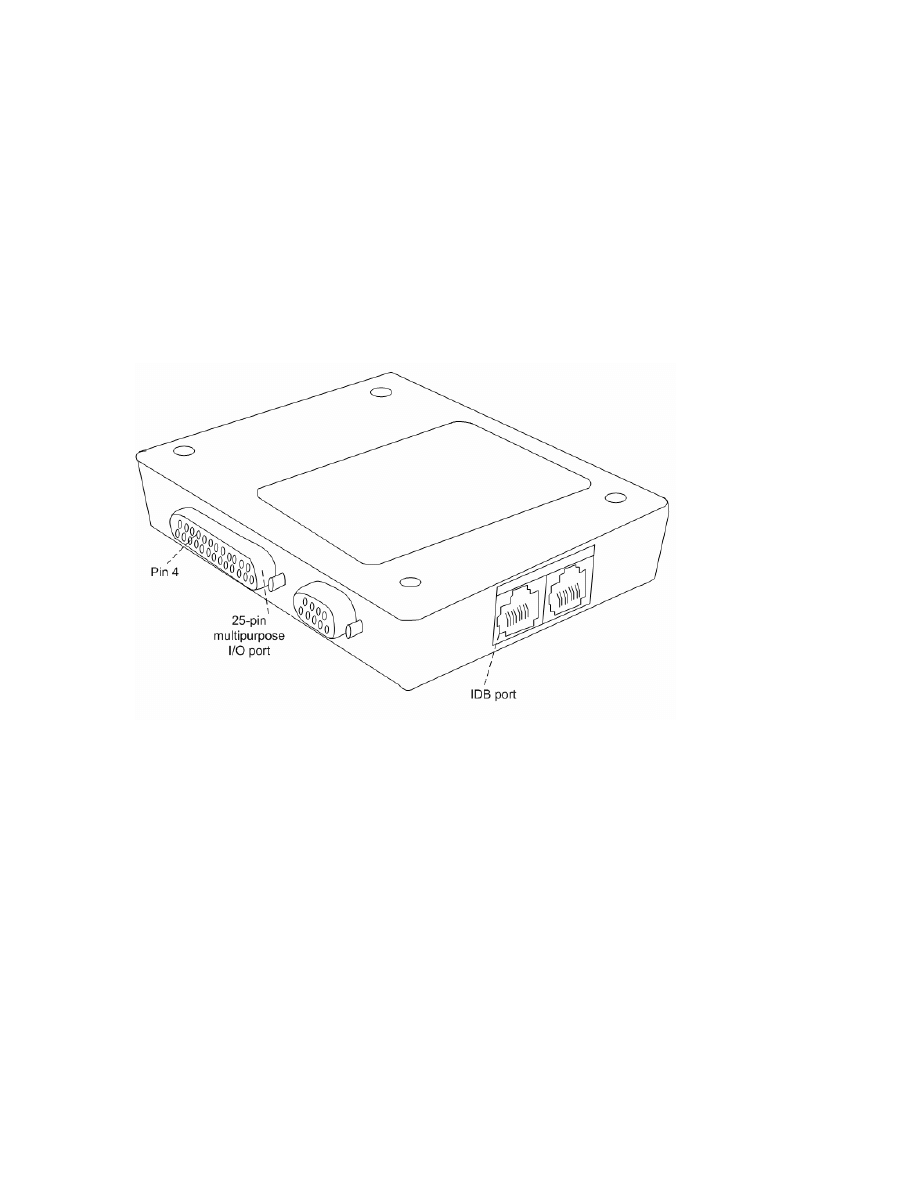
The IDB common interface device (Figure 6) is designed to be of versatile use.
The PIC algorithm to detect remote control button pushes would be designed as an edge-
triggered timing device to compare measured pulse widths with a known set of measured
timing ranges for pulses t2, t3 and t4 shown in Figures 4 and 5.
Figure 6 – The IDB common interface
The IDB common interface uses a PIC 18F876 microcontroller as its computing
core. The PIC 18F876 has various I/O ports which can be used to read TTL-level data.
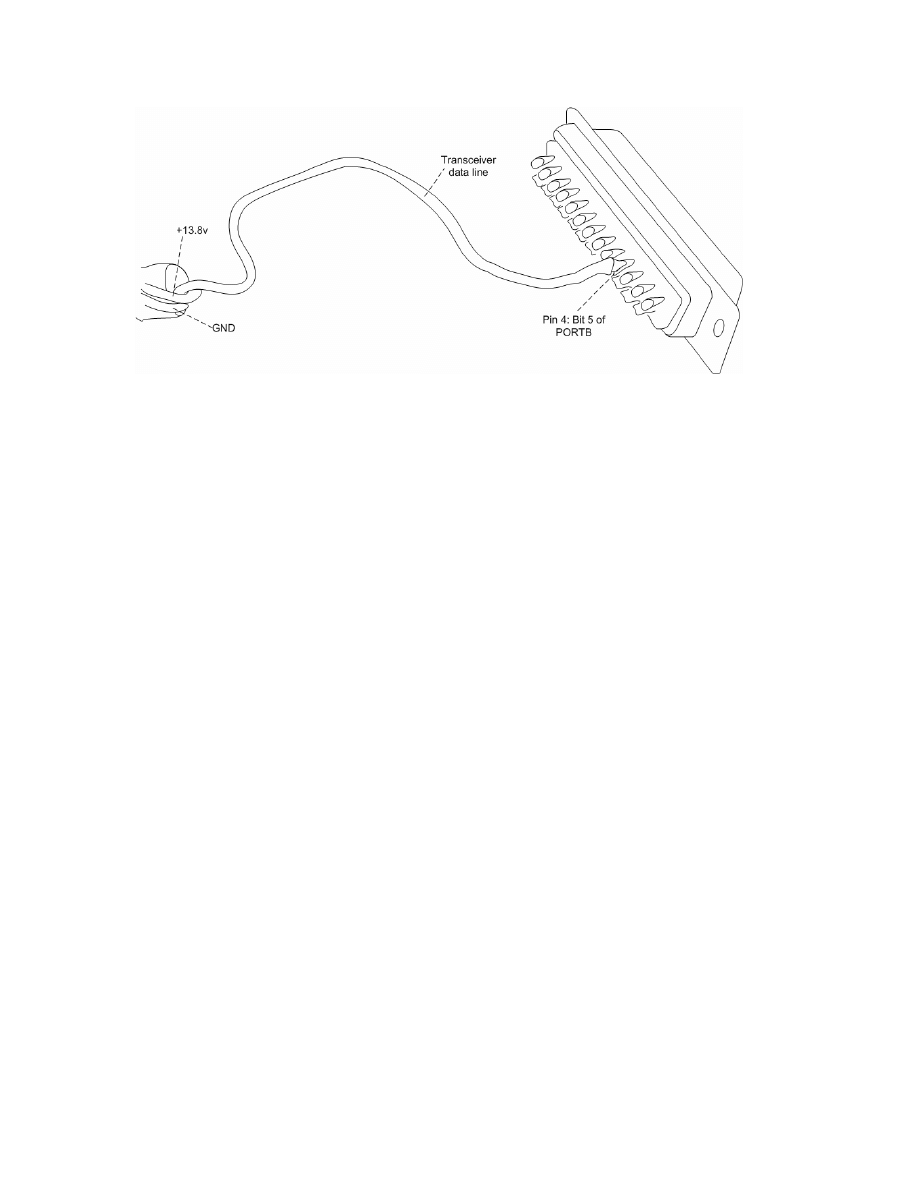
Bit 5 of the PIC 18F876 PORTB was set as an input and used to probe the output signal
of the RC-10 transceiver. In order to easily interface with bit 5 of the PIC 18F876, the
data line of the RC-10 transceiver was connected to pin 4 of the IDB common interface
device’s DB-25 port (Figure 7).
10
Figure 7 – Attaching the RC-10 transceiver to pin 4 of a DB-25 connector
The PIC timer TMR1 was used to collect pulse durations because of its 16-bit
register width and 1:8 timer post-scaling circuitry. The IDB common interface
microcontroller uses a 16MHz clock, whose frequency is divided by a factor of 8 by the
post-scaling circuit of the microcontroller. This allows for pulses of duration 131ms to
be recorded by the timer before a timer register overflow occurrence, or 2µs elapsing per
increment of the 16 bit TMR1 register. Because none of the pulse widths of
consequence exceeded this timer capacity, as pulse t5 was disregarded as irrelevant and
provides sufficient time for CAN packet transmissions, this timer is ideal for recording
the output of the transceiver. Using the 1:8 TMR1 timer post-scaling setting of the
microcontroller, a simple program was written to record the edge-triggered pulse widths
of the output of the transceiver for eventual use in the PIC program. Those timer values
were transmitted through the IDB common interface RS-232 serial port during the 102ms
t5 pulse. A large set of data for each button was recorded with this method in order to
obtain maximum and minimum count values for these pulses.

11
It was discovered that eight of the nine buttons would output a constant pulse time
width format while depressed. However, the large blue “SRC” button would output
pulses t2 and t3 at a width of approximately 6.85ms for the first several transmissions as
the button was held down. It would then proceed to produce pulse widths for t2 and t3 of
approximately 8ms and continue until the button was released. The aforementioned
terminating pulse train that resulted from the release of all nine buttons was
approximately identical for each button, and was also analyzed for its maximum and
minimum times. Tables 2, 3 and 4 show TMR1 maximum and minimum number
increment data for pulses t2, t3 and t4. The maximum and minimum range in the
eventual detection algorithm was extended past the maximums and minimums recorded
experimentally for each button to compensate for possible flukes.
Pulse T2
MAX increments
MIN increments
SRC LO
3425
3361
SRC HI
4031
3954
OK 3728
3663
UP 1913
1846
DOWN 2215
2145
LEFT 3111
3042
RIGHT 2795
2747
VOLUME UP
1292
1227
VOLUME DOWN
1593
1518
MUTE 2508
2430
RELEASE / TERMNIATION
985
927
Table 2 – Maximum and minimum TMR1 increment counts for pulse t2. Release/termination pulse
is measured to be approximately constant for all buttons.

12
Pulse T3
MAX increments
MIN increments
SRC LO
3411 3395
SRC HI
4017 4001
OK
3712 3698
UP
1897 1882
DOWN
2209 2184
LEFT
3094 3080
RIGHT
2795 2761
VOLUME UP
1299 1273
VOLUME DOWN
1600 1574
MUTE
2496 2466
RELEASE / TERMNIATION
987 975
Table 3 – Maximum and minimum TMR1 increment counts for pulse t3. Release/termination pulse
is measured to be approximately constant for all buttons.
MAX increments
MIN increments
Pulse T4
323 285
Table 4 – Maximum and minimum TMR1 increment counts for pulse t4. Pulse t4 is measured to be
approximately constant for all buttons.
After the pulse widths were recorded, they were implemented into an algorithm
written for the microcontroller in the PIC-C programming language. The microp()
function, which uses the IDB network address 0x2e, was modified from strictly hardware
PTT button duties to this more complex multi-case pulse train detection scheme. A
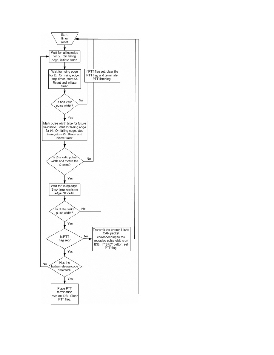
flowchart of the microp() function is shown in Figure 8. It would be trivial to create a
new special purpose IDB address for this algorithm. Table 5 and Table 6 show the pulse
measurement boundaries for t2/t3 and t4 respectively that were eventually implemented
into the microcontroller algorithm.

13
Pulse T2 & T3
MAX increments
MIN increments
SRC LO
3450
3330
SRC HI
4100
3900
OK 3750
3625
UP 1950
1825
DOWN 2250
2120
LEFT 3150
3030
RIGHT 2845
2710
VOLUME UP
1335
1200
VOLUME DOWN
1640
1500
MUTE 2530
2400
RELEASE / TERMNIATION
1000
900
Table 5 – Implemented maximum and minimum TMR1 increment counts for pulses t2 and t3.
MAX increments
MIN increments
Pulse T4
350 250
Table 6 – Implemented maximum and minimum TMR1 increment counts for pulse t4.
14
Figure 8 – Flowchart of the modified microp() function.

15
Detection codes for all of the remote control buttons barring the “SRC” PTT
button are transmitted each time a known pulse train is detected. The unique 1-byte CAN
packets assigned to each button are recorded in Table 7. Since the PTT button works on
the principle of push, hold, and release, a static flag is used to keep track of the position
of these PTT button states. If the PTT “listen” code has been transmitted, the flag is set
to indicate such, and subsequent detections of the “SRC” button code will not result in
repeated transmissions of the 1-byte 0x67 “listen” code. If the button is released while
the PTT button is in the “listen” state, a “terminate listening” code 0x68 is placed on the
IDB when the release pulse train is detected, and the PTT static flag is set to its “not
listening” state. Hence, a PTT code is not placed on the IDB network every time the
“SRC” pulse train is detected, only on instances of depression and release.
Button 1-byte
CAN
Packet
SRC Press
0x67
SRC Release
0x68
Up Arrow
0x65
Down Arrow
0x63
Left Arrow
0x64
Right Arrow
0x62
OK Button
0x66
Volume Up Button
0x60
Volume Down Button
0x61
Mute Button
0x59
Table 7 – 1-byte packet values assigned to button detection states

16
PROJECT54 DLL: REMOTECTRL
A Project54 DLL is a program written in C++, whose purpose is to add
functionality from IDB devices and to communicate with or receive data from existing
Project54 applications. Pre-existing software functions for easy acquisition and
manipulation of Microsoft Windows registry data (RegComlib.h), creation of Project54
graphical user interface (GUI) elements (P54Guilib.h), the ability to send messages to
other Project54 applications (P54Iface.h), and IDB data I/O (IdbComlib.h) can be used to
create a Project54 application. A Project54 application called RemoteCtrl.dll was created
to receive and act upon 1-byte CAN packets transmitted by the microcontroller program
on the IDB, listed in Table 7. The Project54 software libraries used for RemoteCtrl were
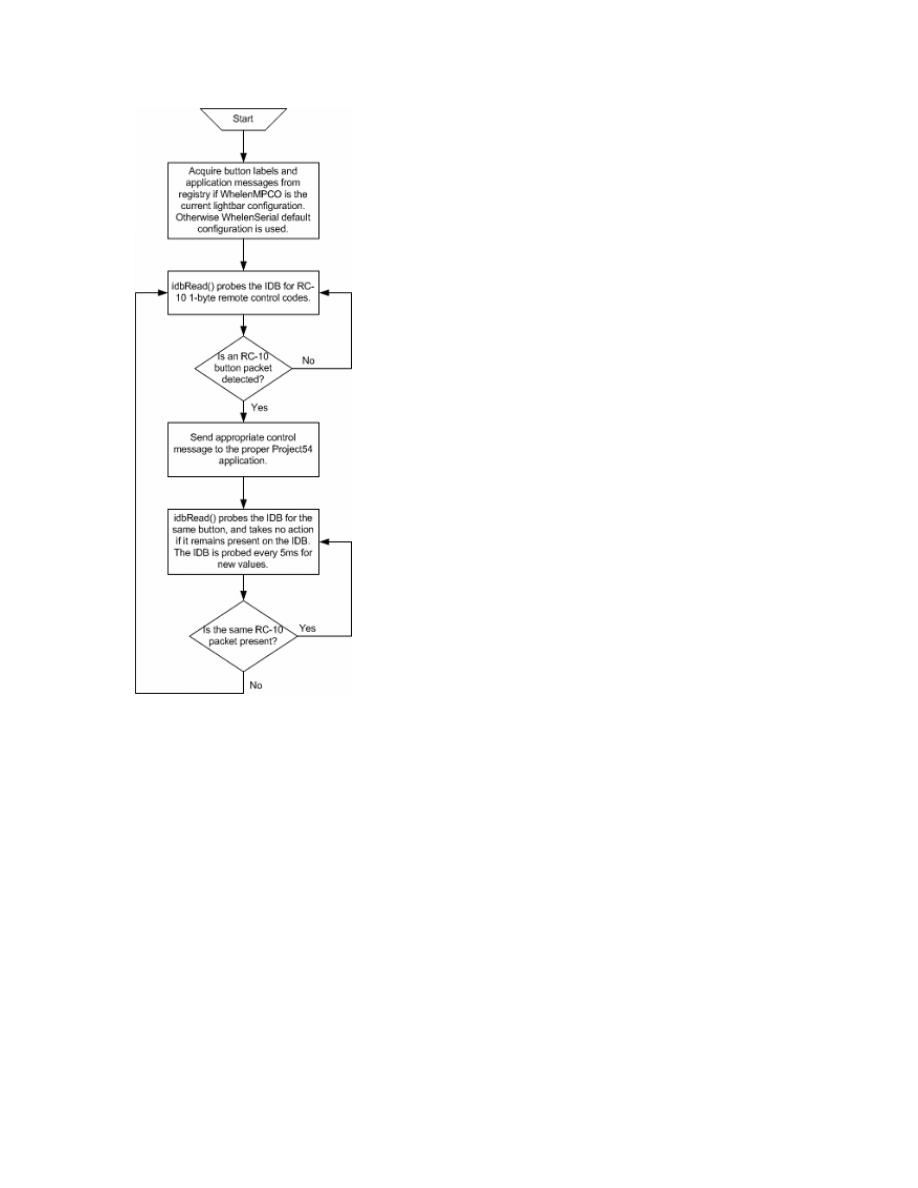
RegComlib.lib and IdbComlib.lib. RemoteCtrl performs two functions: it continually
probes the IDB for the eight non-“SRC” RC-10 CAN packets using the IdbComlib
function idbRead(), and scans the Windows 2000 registry for configurable application
messages and the Project54 applications associated with them. The “SRC” button
packets are handled as they would be with a hardware PTT button, through the Project54
PushTalk application. The RemoteCtrl application detects if the WhelenMPCO
application is set as the currently used light-bar. If so, RemoteCtrl draws application
messages from the registry with the RegComlib function getRegIntValue(), and uses them
for message passing upon the receipt of function packets from the IDB. If WhelenMPCO
is not the current light-bar, the WhelenSerial light-bar default settings for applications
and application messages are used. The RemoteCtrl program flowchart is shown in
Figure 9.
17
Figure 9 – Flowchart of RemoteCtrl.dll
Integer values which correspond to Project54 application functionality are stored
in the Windows 2000 registry key
HKEY_LOCAL_MACHINE\SOFTWARE\Catlab\Project54\remotectrl\Parameters
,
and
are retrieved by RemoteCtrl. These integer values are listed in Table 8. RemoteCtrl has
the ability to send messages to several other Project54 applications, which include:
lightsapp, pscreen, recordsapp, radioapp, radarapp, gpsapp, and mainscreen, which all
have unique Component Object Model (COM) identifiers. These identifiers are retrieved
with the RegComLib function getRegStringValue().

18
Integer Value
Functionality/Defaults to
Application Associated With
0 Disabled
None
1 MPCO Custom/Lights & Siren On
lightsapp
2 MPCO Custom/Front Strobes On
lightsapp
3 MPCO Custom/Rear Strobes On
lightsapp
4 MPCO
Custom/Strobes
On
lightsapp
5 MPCO
Custom/Wig-Wags
On
lightsapp
6 MPCO Custom/Take Downs On
lightsapp
7 MPCO Custom/Rear Floods On
lightsapp
8 MPCO Custom/Left Alley On
lightsapp
9 MPCO Custom/Right Alley On
lightsapp
10 Siren
On
lightsapp
16 MPCO Custom/Lights & Siren Off
lightsapp
17 MPCO Custom/Front Strobes Off
lightsapp
18 MPCO Custom/Rear Strobes Off
lightsapp
19 MPCO
Custom/Strobes
Off
lightsapp
20 MPCO
Custom/Wig-Wags
Off
lightsapp
21 MPCO Custom/Take Downs Off
lightsapp
22 MPCO Custom/Rear Floods Off
lightsapp
23 MPCO Custom/Left Alley Off
lightsapp
24 MPCO Custom/Right Alley Off
lightsapp
25 Siren
Off
lightsapp
32 Radar Audio Up
radarapp
33 Radar
Range
Up
radarapp
34 Radar
Brightness
radarapp
35 Front
Antenna
radarapp
36 Rear
Antenna
radarapp
37 Squelch
On
radarapp
38 Squelch
Off
radarapp
48 Radio
Volume
Up
radioapp
49 Radio
Volume
Down
radioapp
50 Channel
Up
radioapp
51 Channel
Down
radioapp
52 Troop
Up
radioapp
53 Troop
Down
radioapp
54 Scan
On
radioapp
55 Scan
Off
radioapp
64 Show
Window
mainscreen
65 Show
Window
pscreen
66 Show
Window
recordsapp
67 Show
Window
radioapp
68 Show
Window
lightsapp
69 Show
Window
radarapp
70 Show
Window
gpsapp
71 Lights
Off
lightsapp
Table 8 – Registry settings and their corresponding application functionality

19
When RemoteCtrl finds that a particular button of the eight non-“SRC” buttons
has been pressed, a message of functionality is sent to the application associated with that
button using the P54Iface.h four-argument function Message(), which is condensed down
to a two-message function called sendMessageToApp(), with arguments for destination
application and message content. For example, a message may be sent to the radar
application to force the radar application to activate the radar’s rear antenna. The C++
function to elicit this response would appear as such:
sendMessageToApp(radarapp,L“REAR ANTENNA”);
If WhelenMPCO is the active system light-bar configuration, then application
function messages are drawn from the strings in the Windows 2000 registry key
HKEY_LOCAL_MACHINE\SOFTWARE\Catlab\Project54\WhelenMPCO\Vocabulary
for switches one through three and buttons two through six, and are stored in character
arrays of wide character type. Otherwise, RemoteCtrl reverts to the WhelenSerial light-
bar configuration, and uses the application messages associated with it.

20
CONFIGURATION APPLICATION: REMOTECONFIGURATION
A stand-alone MFC C++ Windows 2000 executable called RemoteConfiguration
was written to manipulate the RemoteCtrl registry parameters as to allow an end-user to
configure eight out of the nine remote control buttons to perform various functions with
the Project54 software. RemoteConfiguration uses the registry manipulation functions
provided by the Project54 header file RegComlib.h in order to store and retrieve integer
values for the eight programmable remote control buttons, located in the key
HKEY_LOCAL_MACHINE\SOFTWARE\Catlab\Project54\remotectrl\Parameters
of the
Windows 2000 system registry. RemoteConfiguration manipulates the same integer
values that the RemoteCtrl application reads its settings from, shown in Table 8. The
RegComlib functions getRegIntValue() and setRegIntValue() are used to read and write
these integer values from the Windows 2000 registry. RemoteConfiguration will also
automatically detect the light-bar configuration. If the program finds that WhelenMPCO
is the system’s current light-bar configuration, it will draw button labels for the
application’s radio buttons which correspond to switches one through three and buttons
two through six from the Windows 2000 registry using the RegComlib function
getRegStringValue(). String values for switches one through three and buttons two
through six are stored in the Windows 2000 registry key
HKEY_LOCAL_MACHINE\SOFTWARE\Catlab\Project54\WhelenMPCO\ButtonLabel.
If WhelenMPCO is found to not be the default light-bar installation, then
RemoteConfiguration will revert to configuration of the standard WhelenSerial type
light-bar.
21
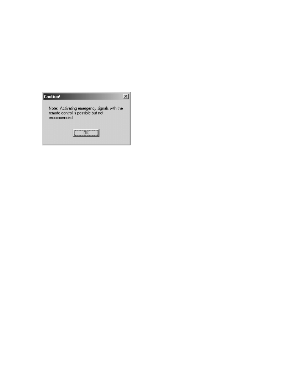
When the RemoteConfiguration program is executed, a disclaimer dialog box
pops up, as shown in Figure 10. This dialog is included to warn the user that because the
automobile driver may accidentally press buttons on the remote control, that activation of
emergency signals and sirens may not be advisable.
Figure 10 – Warning dialog box for RemoteConfiguration.
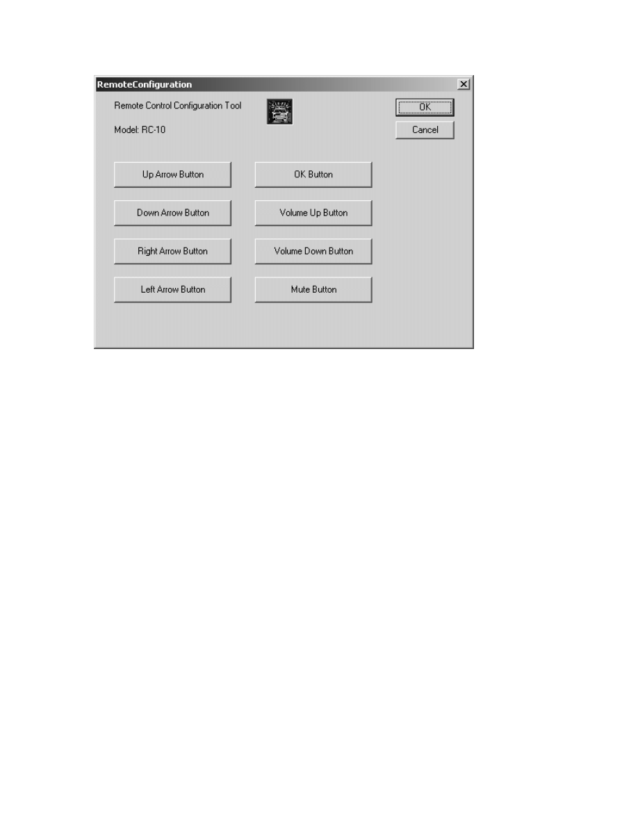
After pressing the “OK” button on the warning dialog box, the warning will
disappear, and the configuration application can be operated to create or disable
functionality for any of the eight configurable buttons on the RC-10 remote control, as
shown in Figure 11. Eight buttons on the next dialog can be pressed, which will allow
the application user to modify the remote control button settings. If there are valid
integer values stored in the
HKEY_LOCAL_MACHINE\SOFTWARE\Catlab\Project54\remotectrl\Parameters
registry key, the RegComlib function getRegIntValue() is used to retrieve them, and they
will be automatically loaded by the program and used as a default until they are modified.
Otherwise, each integer value in this key will be initialized to 0, the “Disabled” setting.
Pressing the “OK” button will store any changes made to the RemoteCtrl registry
parameters. Pressing the “Cancel” button will have no effect on the registry, and will
abandon any changes made on the remote control button settings.
22
Figure 11 – The RemoteConfiguration main dialog.
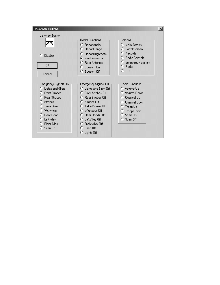
When one of the configuration buttons is pressed, a dialog to configure the
specified RC-10 button will pop up and allow the user to choose some functionality or
disable the remote control button. Figure 12 shows the configuration dialog for the up
arrow button on the RC-10 remote control.
23
Figure 12 – The configuration dialog for the RC-10 up arrow button.
Any of the radio buttons on the configuration dialog may be chosen as a setting
for the remote control button. When the “OK” button is pressed, whatever radio button
has been selected will be stored in a list until the “OK” button in the main configuration
dialog box is pressed. If the “Cancel” button on a button configuration dialog is pressed,
any changes to radio button storage will be discarded, and the value stored in the registry
at the time will be reverted back to the next time the same configuration dialog is
activated.

24
CONCLUSION
The Blaupunkt model RC-10 infrared remote control was created specifically to
be attached to the steering wheel of an automobile. It is molded and designed in order to
be ergonomically appealing and easy to use for the automobile operator while in the
process of driving an automobile. The remote control transmits infrared beams to a
transceiver, which translates the infrared pulse transition levels into electrical pulses.
Three pieces of software were written to integrate the RC-10 remote control with
the Project54 system. The IDB common interface was programmed to recognize the
transceiver-side codes associated with the nine buttons of the RC-10 remote control.
Pulses from the transceiver are captured by creating a circuit between pin 4 of the IDB
common interface device and the data line output of the transceiver. When the
microcontroller ascertains which button had been pressed, an identifier is transmitted
across the IDB in the form of a 1-byte data packet. This packet is then recognized by a
Project54 DLL, RemoteCtrl, and depending on what function is assigned to that
particular button, RemoteCtrl sends functional messages to other Project54 applications
to evoke a program response. Finally, the configuration application is used by an end
user to assign functionality to the eight configurable buttons of the RC-10 as to provide
some functionality for the RemoteCtrl DLL to act upon.
Wyszukiwarka
Podobne podstrony:
Biogenesis of the gram negative Nieznany
An analysis of the European low Nieznany
SHSBC347 THE INTEGRATION OF AUDITING
Endoscopic investigation of the Nieznany
Multistage evolution of the gra Nieznany
asm state of the art 2004 id 70 Nieznany (2)
Modeling Of The Wind Turbine With A Doubly Fed Induction Generator For Grid Integration Studies
Availability and?scription of the File Checksum Integrity Verifier utility
A History of the Evolution of E Nieznany (2)
DYNAMIC BEHAVIOUR OF THE SOUTH Nieznany
Informational Passages RC Houses of the World
(09) The Integration of Body Mind Soul Through Meditation
Informational Passages RC Empress of the Blues
Miller B L On the integration of elementary functions computing the logarithmic part (phd thesis, T
’The Integration of Ethnic Minorities Gypsies, Refugees and Immigrants
Ibison & Puthoff Relativistic Integro Differential Form Of The Lorentz Dirac Equation In 3D Without
The Integration of Ethnic Minorities Gypsies, Refugees and Immigrants
więcej podobnych podstron