
F2833x - Numerical Systems
4 -1
Introduction
One of the most important factors in embedded control is determining the computing time for a
given task. Because embedded control has to cope with its tasks in a given and fixed amount of
time, we call this “Real-Time Computing”. And, as you know, time goes very quickly. If the
device is also responsible for control actions, such as sampling sensor signals, deviation control
and adjusting actuator output signals then the term “Real-Time Control” is used.
Therefore, one of the characteristics of a processor is its ability to do mathematical calculations in
an optimal and efficient way. In recent years, the size of mathematical algorithms that have been
implemented in embedded controller units has increased dramatically. Just take the number of
pages for the requirement specification for one of the various electronic control modules for a
passenger car:
•
1990: 50 pages,
•
2000: 3100 pages
(Source: Volkswagen AG)
So, how does a processor operate with all these mathematical calculations? And, how does the
processor access and process data?
You probably know that the ‘native’ numbering scheme for a digital controller is binary numbers.
Unfortunately, all process values are either in the format of integer or real numbers. Depending
on how a processor deals with these numbers in its translation into binary numbers, we
distinguish between two basic types of processor core:
•
Floating-point Processors
•
Fixed-point Processors
This chapter will start with a brief comparison between the two types of processor.
After a brief discussion about binary numbers, we will then look into the different options to use
the fixed-point unit of the F2833x. It can perform various types of mathematical operations in a
very efficient way, using only a few machine clock cycles.
However, most of today’s numerical simulation systems, such as MATLAB and Simulink from
The Mathworks Corp., operate on floating-point numbers. If such a simulation project is later
implemented in a fixed-point microcontroller, a set of library functions is used to operate on
floating-point numbers. The result will be a noticeably slower performance of such a system. But
not so for the F2833x! This family of devices have an additional floating-point hardware unit,
which can directly operate on floating-point numbers!
A second option for the fixed-point part of the F2833x is called “IQ-Math”. Texas Instruments
provides a library that uses the internal hardware of the C28x in the most efficient way to operate
with 32bit fixed-point numbers. Taking into account that most process data usually do not exceed
a 16-bit resolution, the library gives enough headroom for advanced numerical calculations. The
latest version of Texas Instruments “IQ-Math” Library can be found with literature number
“SPRC087” at
. We will discuss this library in more detail in Chapter 17.
Numbering Systems

Module Topics
4 - 2
F2833x - Numerical Systems
Module Topics
Numbering Systems ....................................................................................................................................4-1
Introduction .............................................................................................................................................4-1
Module Topics ..........................................................................................................................................4-2
Floating-point, Integer and Fixed-point ..................................................................................................4-3
Processor Types ...................................................................................................................................4-4
IEEE 754 Floating-point Format .............................................................................................................4-5
Integer Number Basics .............................................................................................................................4-8
Two’s Complement representation ......................................................................................................4-8
Binary Multiplication ..........................................................................................................................4-8
Binary Fractions ....................................................................................................................................4-10
Multiplying Binary Fractions ............................................................................................................4-10
The “IQ”-Format...................................................................................................................................4-12
Fractional Data in C ...........................................................................................................................4-15
Lab4: Fixed-point and Floating-point ..................................................................................................4-16
Objective............................................................................................................................................4-16
Procedure ...........................................................................................................................................4-16
Open Files, Create Project File ..........................................................................................................4-16
Build and Load ..................................................................................................................................4-17
Test the fixed point solution ..............................................................................................................4-17
Floating Point Library .......................................................................................................................4-19
Floating Point Hardware ....................................................................................................................4-21
Summary: ..........................................................................................................................................4-22

Floating-point, Integer and Fixed-point
F2833x - Numerical Systems
4 - 3
Floating-point, Integer and Fixed-point
All processors can be divided into two groups, “floating-point” and “fixed-point”. However,
recent processor designs, such as the F2833x cover both numerical schemes. The core of a
floating-point processor is a hardware unit that supports floating-point operations according to the
international standard IEEE 754. Intel’s x86-family of Pentium processors is probably the most
popular example of this type. Floating-point processors are very efficient when operating with
floating-point data and allow a high dynamic range for numerical calculations. They are not so
efficient when it comes to control tasks (bit manipulations, input/output control, and interrupt
response) and they are usually more expensive than their fixed-point counter parts.
4 - 2
Floating Point, Integer and Fixed Point
Two basic categories of processors:
Floating Point
Integer/Fixed Point
What is the difference?
What are advantages /
disadvantages ?
Real – Time Control:
Most microcontrollers are fixed - point!
F2833x supports both worlds in
hardware!
Fixed-point Processors are based on internal hardware that supports operations with integer data.
The Arithmetic Logic Unit (ALU) and in case of a Digital Signal Controller (DSC), the hardware
multiply unit expects data to be in one of the fixed-point format data types. There are limitations
in the dynamic range of a fixed-point processor, but they are inexpensive.
But what happens, when we write a program for a fixed-point processor in C and we declare a
floating-point data type ‘float’ or ‘double’? The answer is that library functions are provided to
support this data type on a fixed-point machine. However, these standard ANSI-C functions
consume a lot of computing power. If we take into account the time constrains in a real time
project, we just cannot afford to use these data types in most embedded control applications.
But there is good news: the F2833x offer two solutions to reduce the computing time on floating-
point numbers: (1) an optimized library called “IQ-Math” and (2) an additional floating-point
hardware unit. The IQ-Math Library is a set of highly optimized and high precision mathematical
functions used to seamlessly port floating-point algorithms into fixed-point code. In addition, by
incorporating the ready to use high precision functions, the IQ-Math library can significantly
shorten an embedded control development time. We will discuss this in more detail in Chapter
17.

Floating-point, Integer and Fixed-point
4 - 4
F2833x - Numerical Systems
Processor Types
Most of today’s microprocessors fall into the category of fixed-point types. There is a wide range
of semiconductor manufacturers that offer devices of this type. Just to name a few (the list is in
random order and not exhaustive):
• Atmel AVR, ARM7 and Cortex M3 based devices
• Freescale HCS12X, MC56F83x, MCF523x
• Renesas SH4
• Texas Instruments MSP430, TMS320F280xx, Stellaris M3
• Infineon XE166, XC878
• ST Microelectronics STM32
• NEC V850ES / IE2
• Fujitsu MB91480
• Microchip dsPIC 33FJxx
• NXP LPC2900
• Toshiba TMP370
4 - 3
Processor Types
Floating Point Processors
Internal Hardware Unit to support Floating -
Point Operations
Examples: Intel’s Pentium Series , Texas
Instruments C 6000 DSP
High dynamic range for numeric calculation
Usually more expensive
Integer / Fixed – Point Processors
Fixed Point Arithmetic Unit
Almost all embedded controllers are fixed
point machines
Examples: all microcontroller families, e.g.
Freescale S12X, Infineon C166, Texas
Instruments TMS430, Atmel AVR
Lowest price per MIPS
The world of floating-point processors is not as widespread as the fixed-point group. The most
famous member is Intel’s Pentium family, but there are also others (again, the list is in random
order and not exhaustive):
• Intel x86 Pentium
• Freescale MPC556, PowerPC
• Texas Instruments C6000, DaVinchi , TMS320F2833x

IEEE 754 Floating-point Format
F2833x - Numerical Systems
4 - 5
IEEE 754 Floating-point Format
The IEEE Standard for Floating-Point Arithmetic (IEEE 754) is the most widely-used
standard for floating-point computation, and is followed by many hardware and software
implementations. Many computer languages allow or require that some or all arithmetic be
carried out using IEEE 754 formats and operations. The current version is IEEE 754-2008, which
was published in August 2008; it includes nearly all of the original IEEE 754-1985 (which was
published in 1985) and the IEEE Standard for Radix-Independent Floating-Point Arithmetic
(IEEE 854-1987).
The standard defines:
• arithmetic formats: sets of binary and decimal floating-point data, which consist of finite
numbers, (including signed zeros and subnormal numbers), infinities, and special 'not a
number' values (NaNs)
• interchange formats: encodings (bit strings) that may be used to exchange floating-point
data in an efficient and compact form
• rounding algorithms: methods to be used for rounding numbers during arithmetic and
conversions
• operations: arithmetic and other operations on arithmetic formats
• exception handling: indications of exceptional conditions (such as division by zero,
overflow, etc.)
The standard also includes extensive recommendations for advanced exception handling,
additional operations (such as trigonometric functions), expression evaluation, and for achieving
reproducible results.
11 - 4
IEEE Standard 754 Single Precision
Floating-Point
s eeeeeeee
fffffffffffffffffffffff
0
31 30
23 22
23 bit mantissa (fraction)
8 bit exponent
1 bit sign
Advantage
⇒ Exponent gives large dynamic range
Disadvantage
⇒ Precision of a number depends on its exponent
Case 1:
if e = 255 and f = 0,
then v = NaN
Case 2:
if e = 255 and f = 0,
then v = [(-1)
s
]*infinity
Case 3: if 0 < e < 255,
then v = [(-1)
s
]*[2
(e-127)
]*(1.f)
Case 4: if e = 0 and f = 0, then v = [(-1)
s
]*[2
(-126)
]*(0.f)
Case 5:
if e = 0 and f = 0,
then v = [(-1)
s
]*0
/
/
In the following slides we will focus on the arithmetic numbering formats only.

IEEE 754 Floating-point Format
4 - 6
F2833x - Numerical Systems
32-bit floating-point format (C data type “float):
•
Sign Bit (S):
Negative: bit 31 = 1 / Positive: Bit 31 = 0
•
Mantissa (M):
∑
=
−
−
−
⋅
+
=
+
⋅
+
⋅
+
=
23
1
2
2
1
1
2
1
...
2
2
1
i
i
i
m
m
m
M
Mantissa is adjusted to m
0
= 1; m0 will not be stored in memory!
2
1
<
≤ M
•
Exponent (E):
8 Bit signed exponent, stored with offset, OFFSET = +127
•
Summary:
( )
OFFSET
E
S
M
Z
−
⋅
⋅
−
=
2
1
Example 1:
0x 3FE0 0000
= 0011 1111 1110 0000 0000 0000 0000 0000 B
S = 0
E = 0111 1111 = 127
M = (1).11000 = 1 + 0.5 + 0.25 = 1.75
Z = (-1)
0
* 1.75 * 2
127-127
= 1.75
Example 2:
0x BFB0 0000
= 1011 1111 1011 0000 0000 0000 0000 0000 B
S = 1
E = 0111 1111 = 127
M = (1).011 = 1 + 0.25 + 0.125 = 1.375
Z = (-1)
1
* 1.375 * 2
127-127
= -1.375
Example 3:
Z = - 2.5
S = 1
2.5 = 1.25 * 2
1
1 = E – OFFSET
E = 128
M = 1.25 = (1).01 = 1 + 0.25
Binary : 1100 0000 0010 0000 0000 0000 0000 0000 B = 0x C020 0000

IEEE 754 Floating-point Format
F2833x - Numerical Systems
4 - 7
The advantage of floating-point is its huge dynamic range, which is given by the most positive
exponent (+127, base 2). This exponent plus the maximum mantissa leads to a range of:
Z =
±(1 − 2
24
) ∗ 2
128
≈ ± 3.403 ∗ 10
38
The resolution of a single precision floating-point number is given by the smallest number that
can be represented in this format:
𝑍𝑍 = 2
−23
∗ 2
−126
= 2
−149
≈ 1.401 ∗ 10
−45
It seems that with this dynamic range and resolution we should be able to solve any mathematical
operation. However, when it comes to a simple add operation of a large number and a very small
number, even a floating-point device can fail! Look at the following example for z = x + y:
4 - 5
Floating - Point does not solve
everything!
Example:
x = 10.0
(0x41200000)
+ y = 0.000000240
(0x3480D959)
z = 10.000000240
RIGHT?
WRONG!
You cannot represent 10.000000240 with
single-precision floating point
0x412000000
= 10.000000000
10.000000240
⇐ can’t represent!
0x412000001
= 10.000001000
So z gets rounded down to 10.000000000
Such a rounding error can happen, when we have to add a compensation value (small) to a larger
set point value in a closed control loop! The result would be a somewhat sluggish behavior of our
digital controller.
In the second part of this chapter you will learn that fixed-point numbers do not show this
behavior, if we limit the dynamic range of the numbers to the expected area of a closed loop
control system. When we use the Texas Instruments IQ-Math fixed-point hardware, it will add
10.0 and 0.00000024 to give the exact result of 10.00000024! This is a considerable advantage of
fixed-point numbers over floating-point numbers!

Integer Number Basics
4 - 8
F2833x - Numerical Systems
Integer Number Basics
Two’s Complement representation
The next slides summarize the basics of the two’s complement representation of signed integer
numbers. You should already be familiar with these schemes from basic lessons on computer
engineering or digital systems. If not, use Wikipedia to update yourself!
4 - 6
Integer Numbering System Basics
Binary Numbers
0110
2
= (0*8)+(1*4)+(1*2)+(0*1) = 6
10
11110
2
= (1*16)+(1*8)+(1*4)+(1*2)+(0*1) = 30
10
Two’s Complement Numbers
0110
2
= (0*-8)+(1*4)+(1*2)+(0*1) = 6
10
11110
2
= (1*-16)+(1*8)+(1*4)+(1*2)+(0*1) = -2
10
In the signed integer format, the most significant bit (MSB) carries a negative weight of -1. If the
MSB is set, we have to multiply its coefficient representation by -1 (compare example in the 2
nd
half of Slide 4-6).
Binary Multiplication
Now consider the process of multiplying two two's complement values, which is one of the most
often used operations in digital control. As with “long hand” decimal multiplication, we can per-
form binary multiplication one “place” at a time, and sum the results together at the end to obtain
the total product.
Note: The method shown at the following slide is not the method the F22833x uses to multiply
integer numbers - it is merely a way of observing how binary numbers behave in arithmetic
processes.
The F2833x uses 32-bit operands and an internal 64-bit product register. For the sake of clarity,
consider the example below where we shall investigate the use of 4-bit values and an 8-bit
accumulation:
Integer Number Basics
F2833x - Numerical Systems
4 - 9
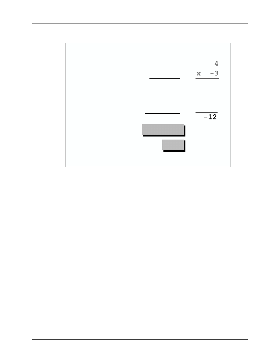
4 - 7
Four-Bit Integer Multiplication
0100
x 1101
00000100
0000000
000100
11100
11110100
Accumulator
Data Memory
11110100
4
x -3
-12
?
Is there another (superior) numbering system?
In this example, consider the following:
•
4 multiplied by (-3) gives (-12) in decimal.
•
The size of the product is twice as long as the input values (4 bits * 4 bits = 8 bits).
•
If this product is to be used in a next loop of a calculation, how can the result be stored
back to memory in the same length as the inputs?
Store back upper 4 Bit of Accumulator? -1
Store back lower 4 Bit of Accumulator? +4
Store back all 8 Bit of Accumulator? overflow of length
•
As a result, scaling of intermediate results is needed!
From this analysis, it is clear that integers do not behave well when multiplied.
The question is: might some other type of integer number system behave better? Is there a
number system where the results of a multiplication have bounds?
The answer is: yes, there is.

Binary Fractions
4 - 10
F2833x - Numerical Systems
Binary Fractions
In order to represent both positive and negative values, the two's complement process will again
be used. However, in the case of fractions, we will not set the LSB to 1 (as was the case for inte-
gers). When we consider that the range of fractions is from -1 to ~+1, and that the only bit which
conveys negative information is the MSB, it seems that the MSB must be the “negative ones posi-
tion”. Since the binary representation is based on powers of two, it follows that the next bit would
be the “one-half” position, and that each following bit would have half the magnitude again.
4 - 8
Binary Fractions
1
0
1
1
•
-1
1/2
1/4
1/8
= -1 + 1/4 + 1/8 = -5/8
Fractions have the nice property that
fraction x fraction = fraction
Multiplying Binary Fractions
When the F2833x performs an integer multiplication, the process is identical for all operands,
integers or fractions. Therefore, the user must determine how to interpret the results. As before,
consider the 4-bit multiply example:
The input numbers are now split into two parts - integer part (I-“integer”) and fractional part (Q-
“quotient”). These type of fixed-point numbers are often called “IQ”-numbers, or for simplicity
sometimes just Q-numbers.
The example below shows 2 input numbers in I1Q3-Format. When multiplied, the length of the
result will add both I and Q portions (see also next slide):
I1Q3 * I1Q3 = I2Q6
Binary Fractions
F2833x - Numerical Systems
4 - 11
4 - 9
Four-Bit IQ - Multiplication
0100
x 1101
00000100
0000000
000100
11100
11110100
11110100
1/2
x - 3/8
-3/16
Accumulator
.
.
Data Memory
-1/4
1110
.
If we store back the intermediate product with the four bits around the binary point we keep the
data format (I1Q3) in the same shape as the input values. There is no need to re-scale any
intermediate results!
Advantage: With Binary Fractions we will gain a lot of speed in closed loop
calculations.
Disadvantage: The result might not be the exact one. As you can see from the slide above we will
end up with (-4/16) stored back to data memory. Bits 2
-4
to 2
-6
are truncated. The correct result
would have been (-3/16).
Recall that the 4-bit input operand multiplication operation is not the real size for the F2833x,
which operates on 32-bit input values. In this case, the truncation will affect bits 2
-32
to 2
-64
. Given
the real size of process data with, let us say 12-bit ADC measurement values, there is plenty of
room left for truncation.
In most cases we will truncate noise only. However, in some feedback applications like Infinite
Impulse Response (IIR)-Filters the small errors can add and lead to a given degree of instability.
It is designer’s responsibility to recognize this potential source of failure when using binary
fractions.
The “IQ”-Format
4 - 12
F2833x - Numerical Systems
The “IQ”-Format
So far we have discussed only the option of using fractional numbers with the binary point at the
MSB-side of the number. In general, we can place this point anywhere in the binary
representation. This gives us the opportunity to trade off dynamic range against resolution.
4 - 10
Fractional Representation
S IIIIIIII
fffffffffffffffffffffff
0
31
32 bit mantissa
Advantage
⇒ Precision same for all numbers in an IQ format
Disadvantage
⇒ Limited dynamic range compared to floating point
-2
I
+ 2
I-1
+ … + 2
1
+ 2
0
.
2
-1
+ 2
-2
+ … + 2
-Q
“IQ” – Format
“I”
⇒ INTEGER – Fraction
“Q”
⇒ QUOTIENT – Fraction
4 - 11
IQ - Examples
S fff
0
3
Most negative decimal number: -1.0
= 1.000 B
Most positive decimal number: + 0.875
= 0.111 B
Smallest negative decimal number: -1*2
-3
(0.125)
= 1.111 B
Smallest positive decimal number: 2
-3
( 0.125)
= 0. 001 B
I1Q3 – Format:
Range:
-1.0 …. 0.875 (
≈ + 1.0)
Resolution:
2
-3

The “IQ”-Format
F2833x - Numerical Systems
4 - 13
4 - 12
IQ - Examples
SII f
0
3
Most negative decimal number: -4.0
= 100.0 B
Most positive decimal number: + 3.5
= 011.1 B
Smallest negative decimal number: -1 * 2
-1
= 111.1 B
Smallest positive decimal number: 2
-1
= 000.1 B
I3Q1 – Format:
Range:
-4.0 …. +3.5 (
≈ + 4.0)
Resolution:
2
-1
4 - 13
IQ - Examples
S fff ffff ffff ffff ffff ffff ffff ffff
0
31
Most negative decimal number: -1.0
1.000 0000 0000 0000 0000 0000 0000 0000 B
Most positive decimal number:
≈ + 1.0
0.111 1111 1111 1111 1111 1111 1111 1111 B
Smallest negative decimal number: -1*2
-31
1.111 1111 1111 1111 1111 1111 1111 1111 B
Smallest positive decimal number: 2
-31
0.000 0000 0000 0000 0000 0000 0000 0001 B
I1Q31 – Format:
Range:
-1.0 …. (+1.0)
Resolution:
2
-31

The “IQ”-Format
4 - 14
F2833x - Numerical Systems
4 - 14
IQ - Examples
S III IIII ffff ffff ffff ffff ffff
0
31
Most negative decimal number: -128
1000 0000. 0000 0000 0000 0000 0000 0000 B
Most positive decimal number:
≈ + 128
0111 1111. 1111 1111 1111 1111 1111 1111 B
Smallest negative decimal number: -1*2
-24
1111 1111. 1111 1111 1111 1111 1111 1111 B
Smallest positive decimal number: 2
-24
0000 0000. 0000 0000 0000 0000 0000 0001 B
I8Q24 – Format:
Range:
-128 …. (+128)
Resolution:
2
-24
Now let us resume the failing floating-point example from the beginning of this module; IQ-Math
can do much better:
4 - 15
IQ-Math can do better!
I8Q24 Example:
x = 10.0
(0x0A000000)
+ y = 0.000000240
(0x00000004)
z = 10.000000240
(0x0A000004)
Exact Result
(this example)
The “IQ”-Format
F2833x - Numerical Systems
4 - 15
Fractional Data in C
If by now you are convinced that fractional data has advantages over other number
representations, the next question is, how do we code fractions in an ANSI-C environment? The
ANSI-C standard does not define a dedicated data type, such as “fractional”. There is a new
ANSI-standard under development, called “embedded C”, which will eventually use this type.
For now we can use the following trick, as shown in Slide 4-16:
4 - 16
How is a fraction coded?
~ 1
0
–½
–1
½
Fractions
~ 32K
0
–16K
–32K
16K
Integers
7FFF
0000
C000
8000
4000
Hex
void main(void)
{
int coef = 32768 * 707 / 1000;
}
⇒
*32768
Example: represent the fraction number 0.707
4 - 17
Fractional vs. Integer
Range
Integers have a maximum range
determined by the number of bits
Fractions have a maximum range of ±1
Precision
Integers have a maximum precision of 1
Fractional precision is determined by
the number of bits

Lab4: Fixed-point and Floating-point
4 - 16
F2833x - Numerical Systems
Lab4: Fixed-point and Floating-point
Objective
The objective of this lab is to practice and benchmark the different options for the F2833x in
terms of numerical systems. We have already discussed that the F2833x supports both fixed-point
and floating-point numbers in hardware. In the following lab we will use the simple code example
from Chapter 3 and compile it for the different numbering systems. To benchmark the results, we
will use a time measurement tool, called “Profiler”, which is part of Code Composer Studio. The
following procedure will summarize all steps discussed in this chapter.
4 - 18
Lab4: fixed - point and floating - point
Benchmark Multiply Operation
k = i * I
Test setup:
1.
Integer variables k and i
2.
Float variables k and i; floating-point library
3.
Float variables k and i; floating-point hardware
unit
Fixed - point
Floating - Point -
Library
Floating - Point -
Hardware
code size (words)
5
89
8
clock cycles (6.67 ns)
4
112
4
Benchmark result:
Procedure
Open Files, Create Project File
1. Using Code Composer Studio, create a new project, called Lab4.pjt in C:\DSP2833x\Labs
(or another working directory used during your class, ask your instructor for specific
location!)
2. Open the file “lab3.c” from project “lab3” and save it as “lab4_1.c” in the working directory
of project “lab4”:
File Open…
“lab3.c”
File Save As… “lab4_1.c”

Lab4: Fixed-point and Floating-point
F2833x - Numerical Systems
4 - 17
3. Add the following files to your project:
Project Add Files to project
• Lab4_1.c
• C:\CCStudio_v3.3\C2000\cgtools\lib\rts2800_ml.lib
• C:\tidcs\c28\DSP2833x\v131\DSP2833x_common\cmd\28335_RAM_lnk.cmd
4. Verify that in Project Build Options Linker the Autoinit- Model field is set to: “Run-
time-Autoinitialisation [-c]”
5. Set the stack size to 0x400: Project Build Options Linker Stack Size
6. Close the Build Options Menu by clicking OK
Build and Load
7. Click the “Rebuild All” button or perform: Project Build and watch the tools run in the
build window. Debug as necessary.
8. Load the output file to the device. Click: File Load Program and choose the output file
“Lab4.out”, which you just generated. Note: the file is stored in the sub-directory “Debug” in
the project folder.
Note: Code Composer can automatically load the output file after a successful build. To
do this by default, click on the menu bar: Option Customize Program Load Op-
tions and select: “Load Program After Build”, then click OK.
Test the fixed point solution
9. Reset the DSP by clicking on Debug Reset CPU, followed by Debug Restart
10. Run the program until the first line of your C code by clicking: Debug Go main. Verify
that in the working region of the source code “Lab4_1.c” is highlighted and that the yellow
arrow for the current Program Counter is positioned at the first line of function “main()”.
11. Remember, that both variables are defined as data type “unsigned int” (16-bit integer
numbers).
12. Now, benchmark the results. First switch into “Mixed-Mode” (Right click into “lab4_1.c”
and select “Mixed-Mode"). Inspect the code-line, which we used to multiply i*i:
Lab4: Fixed-point and Floating-point
4 - 18
F2833x - Numerical Systems
The C line “k = i*i” has been translated into a set of four assembly language instructions.
• The first line moves a 16-bit value from stack memory (to be exact: stack-pointer address
minus 1; that is our local variable ‘i’) to internal register ‘T’.
• Next, register “Data Page (DP)” is loaded with value 0x300. This instruction prepares the
correct access in direct addressing mode for the address of variable ‘k’ in line 4.
• Line 3 multiplies the value in register T by the value from the same stack memory
location, which was used in line 1 (variable ‘i’). The 32-bit product is stored in register
“Accumulator (ACC)”.
• Line 4 stores the lower 16-bits of the 32-bit product (register “Accumulator-low”, AL)
back into memory at address 8 of the active page. Obviously, address 8 on page 0x300 is
the location of global variable ‘k’.
Benchmark #1 (code-size): As you can see from the numbers at the left hand side, our
code snippet “k = i * i” occupies the code memory addresses 0x907D to 0x9081, which gives
a code size of 5 words. (Note: the absolute address numbers might be different on your CCS-
session; however the size should be identical).
Turn off the mixed mode (right mouse click and select “Source Mode”).
Benchmark #2 (execution speed): To measure the number of execution clock cycles,
we can use the CCS “Profiler”:
Profile Clock Enable
Profile Clock View
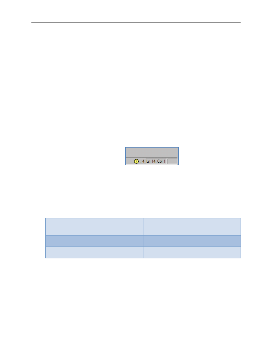
A small yellow profiler clock will appear in the lower right corner of CCS.
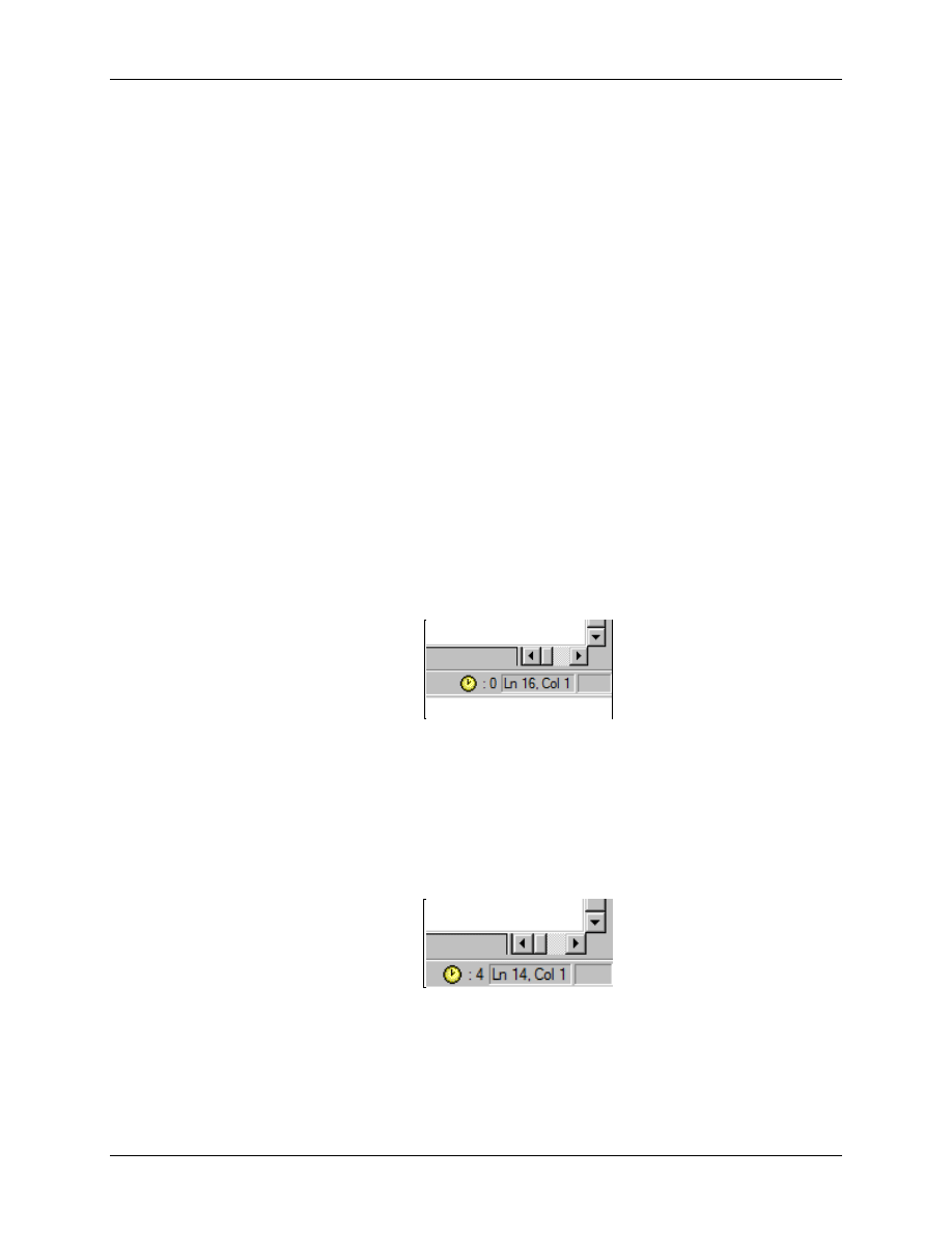
This is our time measurement system. Using single step (F11), run the code until you reach
the line “k = i * i”. The number to the right of the clock gives the number of elapsed clock
cycles. To clear this number, double click on the yellow profiler clock.
Now, with the yellow arrow still on line “k = i * i”, perform a single step (F11). The profiler
clock should show a 4, which indicates that one execution of the line “k = i * i” took 4 clock
cycles. This result corresponds to the four machine code instructions, which we inspected
above. Each instruction is executed in 1 CPU clock cycle.
Result 1 (fixed point math):
•
Code size: 5 words
•
Clock cycles: 4
Lab4: Fixed-point and Floating-point
F2833x - Numerical Systems
4 - 19
Floating Point Library
13. Now let us change the code from fixed-point to floating-point. Change the data types for ‘i’
and ‘k’ from “unsigned int” to “float”.
Save the file as “Lab4_2.c” and add this file to project “Lab4”.
Exclude “Lab4_1.c” from the build. In the project window, right click on “Lab4_1.c”,
select “File Specific Options”, “General” and enable “Exclude from Build”. This
technique allows us to keep more than one source code file in the project tree and we can
change between the different files. Note the missing arrow in the icon for “Lab4_1.c”,
which indicates that this file has been excluded:
14. Rebuild the project and reload the new code:
Project Rebuild All
File Load Program Lab4.out
Debug Reset CPU
Debug Restart
Debug Go main
15. Now, benchmark the results. Again, switch into “Mixed-Mode” (Right click into “lab4_2.c”
and select “Mixed-Mode"). Inspect the code-line, which we used to multiply i*i:
The floating-point line “k = i * i” has been translated in a series of six assembly language
instructions. This is because the variables are now of floating-point type.
• The first line moves a value from stack memory location [SP-4] into register ACC.
This is variable ‘i’ as a first multiply factor.
• Next and in preparation of the function call in line 4, this value is passed as an input
parameter back to stack memory [SP-2].
Lab4: Fixed-point and Floating-point
4 - 20
F2833x - Numerical Systems
• Line 3 reads once more variable ‘i’ and stores it again in register ACC. Register ACC
is used to pass the 2
nd
multiply factor in the function call in line 4.
• Line 4 calls a floating-point multiply function “FS$$MPY”. The assembly
instruction “LCR-Long Call with Return” calls a function from library
“rts2800_ml.lib”, which performs a floating-point multiply on a fixed-point device.
• The last two lines are used to store the result of the function call, which is returned in
register ACC, into memory address 8 of the active data page (address of variable ‘k’).
Benchmark #3 (code-size, floating-point library function):
As you can see from the numbers at the left hand side, our code-snippet “k = i * i” occupies
the code memory addresses 0x9123 to 0x912A, which gives a code size of 8 words. (Note:
the absolute address numbers might be different on your CCS-session; however the size
should be identical). However, this result is not the full story! For code size we have to add
the site of function “FS$$MPY”. When you assembly single step (F11) until you reach the
instruction “LCR” and continue with another “F11”, CCS will open another disassembly
window with the instructions of function “FS$$MPY”. If you scroll down this window, you
will find an instruction “LRETR”, which is the return instruction of this function. The
difference between start- and end- address (0x90C9 - 0x9078) is the size of function
“FS$$MPY”.
Result: 8 + 81 = 89 words code size.
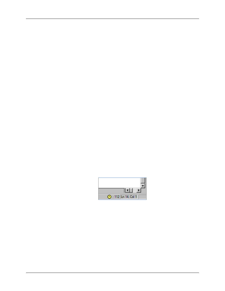
Benchmark #4 (execution speed, floating-point library):
Using the same profiler steps as for the integer code, measure the number of clock cycles for
one floating-point multiplication. From the beginning of “main()”, single step until you reach
the line “k = i * i”. Clear the clock counter and perform another source single step. Note, that
for the first loop, where ‘i’ is zero, you will obtain a relatively small number (32). If you
repeat the test for other values of ‘i’, you will obtain a much greater number (112) of clock
cycles. Obviously, the library function “FS$$MPY” shortens the calculation, if one factor is
zero. Note: The numbers were measured with C compiler - and library version 5.2.2. They
might be different on your installation, but they should be in the same sort of range.
Results (floating point library):
•
Code size: 89 words
•
Clock cycles: 112
Lab4: Fixed-point and Floating-point
F2833x - Numerical Systems
4 - 21
Floating Point Hardware
As a final step we will use the F2833x floating-point hardware unit and replace the floating-point
library. This should reduce both the code size and the number of clock cycles back to the integer
results.
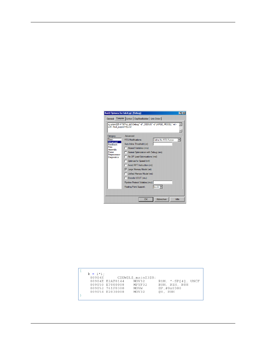
16. Add the floating-point support function to your project:
Project Add Files to Project C:\CCStudio_v3.3\C2000\cgtools\lib\rts2800_fpu32.lib
Set the “file specific options” of “rts2800_ml.lib” to “Exclude from Build”
17. Set the project build options to support floating-point:
Project Build Options Compiler Advanced Floating Point Support: fpu32
18. Rebuild the project and reload the new code:
Project Rebuild All
File Load Program Lab4.out
Debug Reset CPU
Debug Restart
Debug Go main
19. Now, benchmark the results. Again, switch into “Mixed-Mode” (Right click in “lab4_2.c”
and select “Mixed-Mode"). Inspect the code lines, which we used to multiply i*i:
Lab4: Fixed-point and Floating-point
4 - 22
F2833x - Numerical Systems
The floating-point line “k = i * i” has been translated in a series of four assembly instructions,
which use the floating-point hardware unit:
• The first line moves a value from stack memory location [SP-4] into floating-point
register R1H. This is variable ‘i’ as a first multiply factor. Note that register R0H has
already been loaded with the same value some lines before.
• The next line is a floating point multiply operation of R0H * R1H. The product is stored
in register R0H.
• The last two lines store the product (R0H) back in data memory at address 8 of the active
page 0x300.
Benchmark #5 (code-size, floating-point hardware):
As you can see from the numbers at the left hand side, our code-snippet “k = i * i” occupies
the code memory addresses 0x904E to 0x9055, or 8 words.
Benchmark #6 (execution speed, floating-point hardware):
Using the profiler, measure the number of clock cycles for one floating-point multiplication.
From the beginning of “main()”, single step until you reach the line “k = i * i”. Clear the
clock counter and do another source single step. The result is 4!
Summary:
In Lab4 we benchmarked the 3 possible solutions that can be used to multiply two values. For a
fixed-point processor the native numbering scheme is integer. As you can see from the numbers,
both code size and clock cycles are minimal; we can generate an optimal solution for real-time
control, where speed always has the highest priority.
Fixed-point
Floating-Point-
Library
Floating-Point-
Hardware
code size (words)
5
89
8
clock cycles (6.67 ns)
4
112
4
However, if the software designer decides to use floating-point data types for variables k and i,
the library function will dramatically increase both code size and number of clock cycles. Such a
solution could lead to code, which could well be too slow for use in real-time control. For most
microcontrollers this is the end of the road.
Not so for the F2833x! If we enable floating-point hardware support, we easily can use floating-
point data types with the same speed factor as in fixed-point! The code size is a little bit larger
than for fixed-point numbers, but in most cases this does not matter.
Document Outline
- Numbering Systems
Wyszukiwarka
Podobne podstrony:
AG 04 id 52754 Nieznany
43 04 id 38675 Nieznany
matma dyskretna 04 id 287940 Nieznany
Fizjologia Cwiczenia 04 id 1743 Nieznany
lab 04 id 257526 Nieznany
bd lab 04 id 81967 Nieznany (2)
B 04 x id 74797 Nieznany (2)
k 37 04 id 229299 Nieznany
ais 04 id 53433 Nieznany (2)
Module 03 id 305940 Nieznany
al1 lisp 04' id 54559 Nieznany (2)
MD cw 04 id 290125 Nieznany
cw PAiTS 04 id 122323 Nieznany
Perswador 04 id 354974 Nieznany
bik 02 2009 04 id 85660 Nieznany
2IA PS2 2012 2013 04 B id 32601 Nieznany (2)
er 05 04 id 162953 Nieznany
Module 05 id 305943 Nieznany
więcej podobnych podstron