
175 c.c. Bantam Supreme. Model D14/4
175 c.c. Bantam Sports. Model D14/4S
175 c.c. Bushman. Model D14/4B
INSTRUCTION MANUAL

175 c.c. BANTAM Supreme. Model D14/4
175 c.c. BANTAM Sports. Model D14/4S
175 c.c. BUSHMAN. Model D14/4B
B.S.A. MOTOR CYCLES LTD., ARMOURY ROAD,
BIRMINGHAM, 11
ENGLAND
Telephone: Birmingham, VICtoria 2381
Telegrams and Cables: “SELMOTO,” Birmingham.
B.S.A. Motor Cycles Ltd. Reserve the right to alter the designs or any
constructional details of their manufacture at any time without giving notice.
Xxxx
Reproduced August 2003 by Tom Seale
Printed in England
Copyright B.S.A. Co. Ltd.
July, 1967
I N S T R U C T I O N M A N U A L

This Instruction manual is intended to acquaint
the B.S.A. owner with details of the controls,
general maintenance and technical data which
may be required for normal operation of the
machine.
It does not contain the information necessary
to carry out complete stripping for major
overhauls, but if any owner feels competent to
carry out this type of work, a service manual and
an illustrated spares catalogue for this machine
can be obtained from his B.S.A. spares stockist
or local dealer.
Owners in the British Isles can obtain these
publications direct from B.S.A. Motor Cycles
Ltd., Service Department, Armoury Road,
Birmingham 11. Always quote full engine and
frame numbers when ordering these
publications.
2
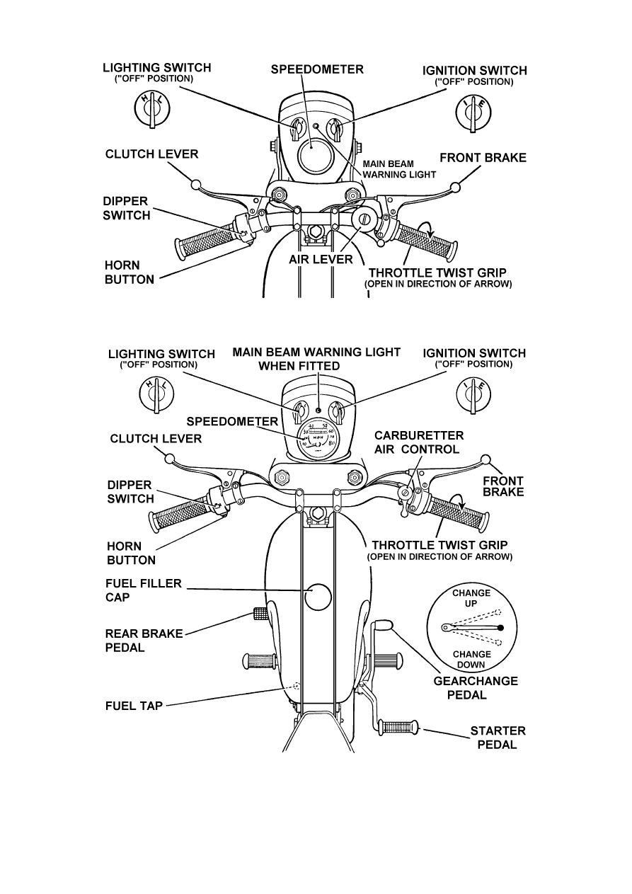
The controls of the Bantam Sports. Note: Bushman models are not fitted with an
ignition switch, main beam warning light, or parking light, but are otherwise
similar.
Fig. 1. The Controls
The lower illustration shows the controls for the Bantam Supreme.
3

CONTENTS
AIR CLEANER
. .
. .
. .
. .
. .
. .
. .
BRAKES
. .
. .
. .
. .
. .
. .
. .
. .
CARBURETTER . .
. .
. .
. .
. .
. .
. .
FRONT CHAIN . .
. .
. .
. .
. .
. .
. .
REAR CHAIN
. .
. .
. .
. .
. .
. .
. .
CLEANING
. .
. .
. .
. .
. .
. .
. .
CLUTCH . .
. .
. .
. .
. .
. .
. .
. .
CONTROLS
. .
. .
. .
. .
. .
. .
. .
CYLINDER HEAD AND BARREL REMOVAL . .
. .
DRIVING . .
. .
. .
. .
. .
. .
. .
. .
DECARBONISING
. .
. .
. .
. .
. .
. .
ELECTRICAL EQUIPMENT . .
. .
. .
. .
. .
FORKS
. .
. .
. .
. .
. .
. .
. .
. .
GEARBOX . .
. .
. .
. .
. .
. .
. .
. .
HUBS
. .
. .
. .
. .
. .
. .
. .
. .
IGNITION TIMING
. .
. .
. .
. .
. .
. .
LUBRICATION CHART
. .
. .
. .
. .
. .
LUBRICATION (ENGINE)
. .
. .
. .
. .
. .
ROUTINE MAINTENANCE . .
. .
. .
. .
. .
REAR SUSPENSION . .
. .
. .
. .
. .
. .
RUNNING-IN
. .
. .
. .
. .
. .
. .
. .
SPARKING PLUG
. .
. .
. .
. .
. .
. .
STEERING HEAD
. .
. .
. .
. .
. .
. .
TECHNICAL DATA
. .
. .
. .
. .
. .
. .
TRANSMISSION . .
. .
. .
. .
. .
. .
. .
WHEEL REMOVAL (FRONT)
. .
. .
. .
. .
WHEEL REMOVAL (REAR) . .
. .
. .
. .
. .
WIRING DIAGRAM
. .
. .
. .
. .
. .
. .
20
28
18
24
28
11
25
7
15
8
15
30 and 32
28
26
26
13
22, 23
12 and 22
11
29
10
17
29
5 and 6
24
27
27
34, 35
4
pages

TECHNICAL DATA
Engine Number—on top of crankcase below cylinder.
Frame Number—at top of steering head tube.
Engine:
Capacity
. .
. .
. .
. .
. .
. .
. .
. .
. .
Cylinder bore
. .
. .
. .
. .
. .
. .
. .
. .
Stroke
. .
. .
. .
. .
. .
. .
. .
. .
. .
Compression ratio . .
. .
. .
. .
. .
. .
. .
. .
Piston ring gap
. .
. .
. .
. .
. .
. .
minimum
maximum
Sparking plug
. .
. .
. .
. .
. .
. .
. .
. .
Plug points gap
. .
. .
. .
. .
. .
. .
minimum
maximum
Contact breaker points gap
. .
. .
. .
. .
. .
. .
Ignition timing (fixed) . .
. .
. .
. .
. .
. .
. .
173 c.c.
61·5 mm.
58 mm.
10/1
·009 in.
·013 in.
N4
·020 in.
·025 in.
·012 in.
18 degrees
(before
T.D.C.)
Transmission:
Gear ratios . .
. .
. .
. .
. .
. . top
third
second
first
Supreme,
Sports
6·58
8·55
12·04
18·68
Bushman
8·1
10·5
14·8
23·0
Clutch—friction plates . .
. .
. .
. .
. .
4
4
Chain size and pitch
front ⅜ × ·250 in.
. .
. .
. .
. .
. .
rear ½ × ·335 in. roller
. .
. .
. .
. .
50 pitches
120 pitches
50 pitches
128 pitches
Teeth on: engine sprocket
. .
. .
. .
. .
17
17
gearbox sprocket
. .
. .
. .
. .
clutch sprocket. .
. .
. .
. .
. .
rear chainwheel
. .
. .
. .
. .
16
38
47
16
38
58
Capacities:
Fuel tank
. .
. .
. .
. .
. .
. .
. .
. .
. .
Petroil mixture
. .
. .
. .
. .
. .
. .
. .
. .
Gearbox
. .
. .
. .
. .
. .
. .
. .
. .
. .
Front forks . .
. .
. .
. .
. .
. .
. .
. .
. .
1⅞ gallons
See pages
12 and 22
1 pint
⅛ pint
(Supreme),
1
⁄
6
pint
(Sports and
Bushman)
each leg
5

TECHNICAL DATA
Wheels:
Tyre size
. .
. .
. .
. .
. .
. .
Tyre pressure
. .
. .
. .
. .
. .
Brake size . .
. .
. .
. .
. .
. .
front
rear
front
rear
dia.
wide
Supreme,
Sports
3·00—18
3·00—18
16 p.s.i.
22 p.s.i.
5½ in.
1 in.
Bushman
3·00—19
3·00—19
16 p.s.i.
22 p.s.i.
5½ in.
1 in.
Carburation: Amal
Bore . .
. .
. .
. .
. .
. .
. .
. .
Main jet
. .
. .
. .
. .
. .
. .
. .
Pilot jet
. .
. .
. .
. .
. .
. .
. .
Throttle valve
. .
. .
. .
. .
. .
. .
Needle position
. .
. .
. .
. .
. .
. .
Needle jet . .
. .
. .
. .
. .
. .
. .
26 mm.
150
25
3
2
·105
General Details:
Overall length
. .
. .
. .
. .
Wheelbase . .
. .
. .
. .
. .
Ground clearance (at crankcase)
. .
Seat height . .
. .
. .
. .
. .
Overall height
. .
. .
. .
. .
Handlebar width . .
. .
. .
. .
Supreme
77½ in.
50 in.
6¾ in.
31 in.
36½ in.
27¾ in.
Sports
77½ in.
50 in.
6¾ in.
30¼ in.
36½ in.
23 in.
Bushman
78 in.
50 in.
10 in.
30½ in.
40½ in.
27¾ in.
The recommended tyre pressures are based on a rider’s weight of 154
lbs. If the rider is heavier, increase the pressures as follows: —
Front tyre: Add one lb. Per sq. in. for every 28 lb. Increase above
154 lb.
Rear tyre: Add one lb. Per sq. in. for every 14 lb. Increase above
154 lb.
If additional load is carried in the form of a pillion passenger or
luggage, the actual load bearing upon each tyre should be determined
and the pressures increased in accordance with the Dunlop Load and
Pressure Schedule
6

TAKING OVER THE MACHINE
Before running the machine make sure that the fuel tank contains the correct
mixture of oil and petrol, that the gearbox is properly topped up with oil and that the
battery is filled and charged. (See appropriate chapters for filling instructions).
Normally these preparations will be carried out by the dealer who is selling the
machine and the new owner has only to arrange the controls to his liking and the
machine is ready for the road.
The Controls
The new rider should make sure that he is quite familiar with all the controls before
attempting to ride the machine. Most of the controls are adjustable and should be
positioned so that they can be reached without moving the hands from the grips or the
feet from the footrests. Handlebars should be adjusted so that a comfortable and
natural riding position is achieved. Make sure that the bolts retaining the handlebar
clamps are tight after completing any adjustment. Badly positioned controls cause
poor control of the machine and will bring discomfort on long journeys.
Handlebar Controls
Twist Grip.—Mounted on the right handlebar it controls the throttle opening and
consequently the engine speed. To open the throttle (i.e. to increase the engine
speed) turn the grip so that the top moves towards the rider. Excess slackness in the
cable can be removed by means of an adjuster incorporated in the cable at the
carburetter end.
The rotary stiffness of the twist grip can be varied by means of the adjuster screw
and locknut. It is set for average requirements when leaving the factory, but can be
readjusted to suit individual preference.
Front Brake.—Lever mounted on the right handlebar in front of the throttle
control. Grip the lever gently to operate the brake.
Clutch.—The lever is mounted on the left handlebar. Grip the lever to free the
clutch, i.e. to disengage the drive between the engine and the rear wheel.
Horn.—The horn button is mounted on the left handlebar and is incorporated in the
headlight dipper switch.
Headlight Dipper Switch.—Controls the switching from main to dipped headlight
beams and is mounted on the left handlebar.
Cut-out Button.—On Bushman models, an ignition cut-out is provided on the left
handlebar and is mounted on the same body as the horn button and headlight dipper
switch.
Headlight Warning Light.—On Supreme models for U.S.A. only, a red warning
light on the headlight body indicates when the main beam is in use. On Sports
models the warning light is a standard item.
Other Hand Controls
Carburetter Air Control.—Situated on the right handlebar, adjoining the front
brake lever. When closed (moved away from the rider) a rich mixture is provided for
starting purposes. For normal running, the lever should be turned clockwise as far as
possible. Cable adjustment is at the carburetter.
Petrol Tap.—Under the rear end of the tank. To turn on the petrol, pull out the
serrated button and lock in position by turning anti-clockwise. To turn off the petrol,
reverse this procedure.
7

Headlight Switch.—This is operated by a switch on the headlamp, and has three
positions—OFF, LOW (L), and HEAD (H) respectively. The low position is for use
when the machine is stationary and applies only to Supreme and Sports.
Ignition Switch.—(Supreme and Sports models)—This is mounted on the top of
the headlamp and has three positions. With the pointer straight ahead, the ignition is
switched off, and the switch should always be retained in this position when the
engine is stationary, otherwise after several hours (say, over-night) the battery may
become discharged. For normal starting, rotate the switch until the position marked
“I” is straight ahead. For emergency starting with a discharged battery, rotate the
switch until position “E” is straight ahead. (Important—See Electrical Equipment).
Carburetter Tickler.—This is a small plunger above the float chamber. Pressing it
down pushes down the float and frees the needle valve thus permitting the carburetter
to receive excess petrol.
Steering Lock.—Provision is made for locking the steering. Turn the forks to the
left, when the hole in a special frame lug will coincide with the corresponding hole in
the bottom yoke lug. Locking the two lugs together by means of a padlock, prevents
the machine from being driven or wheeled away.
Foot Controls
Rear Brake.—On the left-hand side of the machine controls the rear brake only.
Gear-change Pedal.—On the right-hand side of the engine there are two pedals
one of which projects forward, this being the gearchange pedal. It affects the change
from one gear to another. The lever is of the positive stop type and returns to the
central position after each change. Upward movement of the lever selects the next
higher gear, downward a lower gear. Neutral is between first and second gear.
Starter Pedal.—This is the other pedal on the right-hand side of the engine.
Depression of the pedal rotates the engine.
Instruments
Speedometer.—This is mounted centrally in the headlight body and records speed
and total mileage.
DRIVING
To Start the Engine
On Supreme and Sports models, first turn the ignition switch to the position
marked “I” (see “Controls”). It will be impossible to start the engine until this has
been done.
Stand astride the machine and make sure that the gears are in the neutral position,
which lies between the first and second gears. If there is any doubt about this,
depress the gearchange pedal fully two or three times to engage successively lower
gears, at the same time easing the machine backwards and forwards to allow the gears
to rotate a little and so facilitate gear engagement. When it is certain that first gear is
obtained, raise the pedal by half its normal stroke, so selecting the neutral position.
Should the machine be in gear it will move forward as the starter pedal is depressed.
If the engine is quite cold, depress the carburetter tickler momentarily. Note that it
is neither necessary nor desirable to oscillate the tickler rapidly, as this may damage
the float. Close the carburetter air control, thus giving a rich mixture for starting (see
page 19).
8

Open the twist grip a small amount only, as excessive opening may prevent easy
starting, and push the starter pedal down slowly until resistant is felt; then, without
releasing the pressure on the pedal, give a firm downward swing which should set the
engine in motion. If the engine fails to start at the first attempt, repeat this procedure,
being careful to avoid rapid kicking at the pedal which will serve no purpose and may
damage the operating mechanism.
Note that while it is necessary to use the carburetter air control when starting from
cold, this may not be necessary when the engine is warm, and should certainly not be
so if a re-start is made after a short wait only. During normal running the air control
must always be kept fully open and it should be opened immediately the engine fires,
or should the weather be cold, at the earliest possible moment.
Engaging First Gear
With the engine running slowly, disengage the clutch by gripping the left
handlebar lever and after a brief interval press down the gearchange pedal as far as it
will go, so selecting first gear. If the pedal will not move through its full travel, so
that the gear does not engage, ease the machine backwards or forwards slightly,
maintaining a light pressure on the pedal, until the gear is felt to engage.
Moving Off
Open the throttle slightly and gently release the clutch lever part way, until the
clutch can be felt to take up the drive, and the machine tends to move forward. Open
the throttle a little more to prevent the possibility of stalling the engine, and slowly
release the clutch lever as the machine moves away. Until the lever is completely
released the clutch is not fully engaged, so that the engine should not be speeded up
excessively or the clutch remain partly engaged, for longer than is necessary to get
the machine away in first gear.
Changing Gear (Up)
When the machine is moving steadily with the clutch fully engaged, the next
operation is to engage second gear. Close the throttle, disengage the clutch, and raise
the gearchange pedal as far as it will go, the three movements being performed
simultaneously. Immediately the gear is felt to engage, re-open the throttle and re-
engage the clutch. A similar procedure is necessary for each upward gearchange.
Changing Gear (Down)
Open the throttle slightly, disengage the clutch, and press the gear change pedal
down as far as it will go. Re-engage the clutch as soon as the gear is felt to engage.
Violent pressure on the gear lever is unnecessary, a steady movement of the pedal
being most effective. All downward gearchanges should be made in a similar
manner.
To Select Neutral
Neutral is situated between first and second gears. To select neutral from first
gear, withdraw the clutch and lift the gearchange pedal gently until it is felt to click
into the neutral position. If the lever is lifted up too far it will travel through to
second gear.
9

To Stop the Engine
Select the neutral gear position and close the throttle so reducing the engine speed
to “tick-over”. Turn the ignition switch to the “OFF” or central position, or, on
Bushman models, depress the “cut-out” button to stop the engine.
Notes on Gear Changing
When changing gear, not only should a suitable road speed be selected at which to
perform the operation, but the gear change should be timed in such a way that the
relative speeds of the engine and gearbox coincide as closely as possible. For this
reason, when changing up, the throttle is momentarily closed when disengaging the
clutch, allowing the engine (and corresponding gearbox pinions) to slow down to the
lower speed at which they will operate in the next higher gear.
When changing to a lower gear, the engine speed has to be increased relative to the
road speed, and the throttle should not therefore be closed, but even opened slightly,
while making the change. As soon as the clutch lever is gripped, the engine will
automatically increase in speed, and the lower gear will engage quietly at the correct
speed.
Changing gear therefore whilst appearing complicated is mainly concerned with
the synchronisation of engine speed and road speed, by co-ordination of hand and
foot operations. After a little practice, smooth and quiet gear changes will be
possible at all items and eventually become a purely automatic action.
Using the Gearbox
Correct use of the gearbox must be made in order to obtain best results in all round
performance, especially with regard to acceleration and hill climbing capabilities.
It is not always appreciated that the power developed by an I.C. engine depends
upon the engine speed. Hence, on a machine travelling up hill the engine speed will
fall as a result of the increased load, with a corresponding fall in power output. In
order to maintain sufficient power, a lower gear must be selected in order to increase
the engine speed and so obtain more power.
Similarly, for good acceleration from moderate speeds in top gear, more power is
required and here again the solution is to change down to a lower gear. It is better to
allow the engine to “rev” in a lower gear than to labour in a higher one.
Riding Hints
Use the throttle to control the speed of the machine, as gentle but definite braking
is obtained by merely closing the throttle. On wet roads and particularly under icy
conditions, the use of the engine as a brake is to be recommended. A change to lower
gear increases the braking effect.
Try to anticipate the need to change gear or to brake, so that changes in speed are
smoothly carried out. Always use both brakes together and apply them smoothly and
progressively. Never accelerate or brake fiercely, especially on bends or wet roads.
Both actions are signs of an inconsiderate driver and always remember, a good driver
is the most unobtrusive.
RUNNING-IN
The rider who has just purchased a new machine will do well to remember that all
the internal parts are just as new as the enamel and plating which can be seen, and
they must be well “run-in” before the engine can be given really hard work.
10

The “running-in” process is the most important period in the life of the engine, and
the handling it receives during the first 1,000 to 1,500 miles will determine the
service which it will provide in return.
Running-in should commence at ⅓ to ½ throttle and the throttle opening should be
progressively increased as the mileage builds up, until at the end of the running-in
period full throttle can be employed.
If excessive speeds are used in the early stases, there is risk of seizure and other
troubles and in any case until the machine has been properly run-in it cannot be
expected to give its best performance.
Smooth throttle control and selection of the correct gear for the prevailing
conditions will ease the work of the engine. In particular avoid violent acceleration,
and do not allow the engine to labour on hills in high gear when a change to a lower
gear would ease the load. This ensures that all parts of the machine are properly run-
in and are quite free.
Carry out the periodical maintenance details described later with faithful regularity.
After the first 250 miles (400 km.), remove the smaller of the two screwed plugs
from the bottom of the crankcase and drain out any oil which may have accumulated
there. With the petroil lubrication system employed there is never a considerable
quantity of liquid oil in the crankcase, but whatever oil there is should be drained
away, and this is preferably done while the engine is warm immediately after a run,
as the oil will flow more freely and carry with it any foreign matter which may have
found its way into the crankcase during the running-in process.
Make certain on replacing the plug that it is made really tight in order to prevent
loss of crankcase compression.
During the running-in period the gearbox should also be drained and flushed out
and this is preferably done at the same time as the crankcase is drained. Information
regarding the correct grades of oil is given in the table on page 22.
ROUTINE MAINTENANCE
To keep the machine in good condition and provide trouble-free running,
maintenance must be regularly carried out. The following list of items requiring
regular attention will serve as a guide to the periods between servicing and the
method of carrying out the various adjustments will be found under the appropriate
headings in the later chapters.
Obviously regular and thorough cleaning will keep the machine looking smart and
will help to retain both its new appearance and value. But it helps also to lengthen its
life and maintain efficiency if the cleaning process is carried out correctly.
Take special care to prevent dust and grit from working into such parts as hubs,
carburetter, brakes and gearbox.
To rub dry and caked mud from the frame, tank and mudguards means that the
enamel on these parts will be subjected to an abrasive action which will quickly
destroy the polish. Soak the mud first, and then float it off with copious supplies of
clean water supplied either with a hose or a sponge. If a hose is used, take care not to
direct the stream of water directly on to the hub bearings, and carburetter.
When all dirt is removed, dry and polish. Autobrite is recommended for this
purpose.
The engine and gearbox are best cleaned with a brush and paraffin, and then dried
off with a clean rag.
11

Weekly
page
Check tyre pressures and remove any embedded stones or pieces of
metal.
Oil brake pedal pivot and all exposed joints and cables.
Examine the battery and top up if necessary. More frequent
examination is advisable in a hot climate
. .
. .
. .
. .
Check brake adjustment
. .
. .
. .
. .
. .
. .
. .
30
28
Every 1,000 miles
Check rear chain adjustment . .
. .
. .
. .
. .
. .
. .
Check oil level in gearbox and top up if necessary
. .
. .
. .
Clean air filter . .
. .
. .
. .
. .
. .
. .
. .
. .
Grease swinging fork pivots (2)
. .
. .
. .
. .
. .
. .
Grease clutch control . .
. .
. .
. .
. .
. .
. .
. .
Oil central stand pivots.
28
26
20
29
25
Every 2,000 miles
Check tightness of all nuts and bolts.
Change oil in gearbox . .
. .
. .
. .
. .
. .
. .
. .
Grease brake cams.
Grease speedometer drive
. .
. .
. .
. .
. .
. .
. .
26
26
Every 5,000 miles
Check contact breaker adjustment and grease the felt pad
. .
. .
13
Every 10,000 miles
Drain and re-fill front forks . .
. .
. .
. .
. .
. .
. .
28
ENGINE
Lubrication
Lubrication for the engine is provided by oil dissolved in the petrol to provide a
mixture commonly called “petroil”. The filler cap on top of the petrol tank will be
found to incorporate a tubular extension which projects into the tank. This serves as
a measure for lubricating oil and is used for preparing the correct mixture of petrol
and oil required. The correct proportion of oil to petrol is given on page 22, and the
grades of oil recommended should be used, as lighter grades may prove unsuitable.
For correct running of the engine and also for adequate lubrication, it is essential
that the oil should be completely dissolved in the petrol, and it is, therefore,
preferable to use self mixing oils specially prepared for two-stroke engines as
detailed in the list of recommended lubricants (page 22). Alternatively, ready-mixed
oil and petrol can be obtained from dispensers kept by many garages. As the only
lubrication for the engine is by means of fuel drawn in through the carburetter, the
machine must not be coasted downhill for long periods with the throttle shut as the
engine may suffer seizure through lack of lubrication.
The engine mainshaft bearings are automatically lubricated, those on the driving
side from the chaincase, and those on the opposite side from the gearbox. Special
seals prevent transference of this oil to the crankcase.
Contact Breaker Gap
In order to obtain correct timing and proper functioning of the contact breaker, the
points must be set to the correct gap when in the fully opened position, and this
should be checked periodically as recommended above.
12
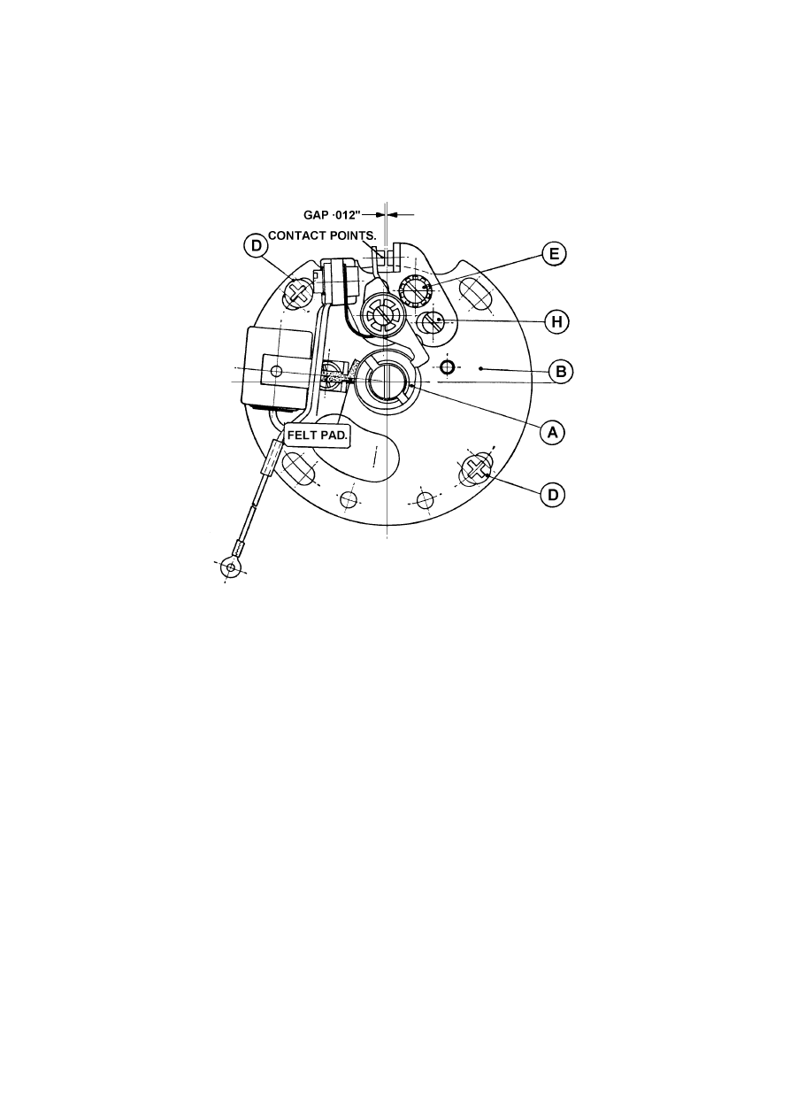
The contact breaker becomes accessible following removal of the screws “G” which
retain cover “F” (Fig. 6). Turn the engine until the points are fully opened and insert
a feeler gauge between them. The correct gap in this position should be ·012 in. (·3
mm.) and if it is found to be incorrect, slacken screw “E” (Fig. 2) and turn the
eccentric pin “H” until the correct gap has been restored, finally tightening screw
“E”.
Fig. 2. The Contact Breaker
Contact Breaker Cam Lubrication.
Apply a very small amount of thin grease (preferably of the high melting point
type) to the felt pad which lubricates the cam. Do not use an excessive quantity
because it is most important that the contact points are kept free from lubricant,
otherwise mis-firing and difficult starting may occur.
Cleaning
If the contact points are burnt or blackened, clean with a fine carborundum stone or
very fine emery cloth, afterwards wiping away any trace of dirt or metal dust with a
clean petrol-moistened cloth.
Ignition Timing
The ignition timing is accurately set within very close limits and there is neither
provision, nor necessity, for manual adjustment of the setting. It cannot be too
strongly emphasised that the ignition timing is correctly set for satisfactory engine
performance and that any attempt to “improve” on the manufacturer’s setting should
be avoided, since it has been determined after careful development.
The contact breaker cam “A”, Fig. 2, is mounted on a tapered extension of the
engine main shaft and its position with reference to the piston is therefore constant.
13
Any variation in timing can be obtained only by moving the contact breaker plate
“8” Fig. 2, which can be rotated through a very small angle after releasing the screws
“D”. Do not forget to re-tighten them securely after the adjustment has been made.
It is emphasised that this is a “works” adjustment rather than one which the private
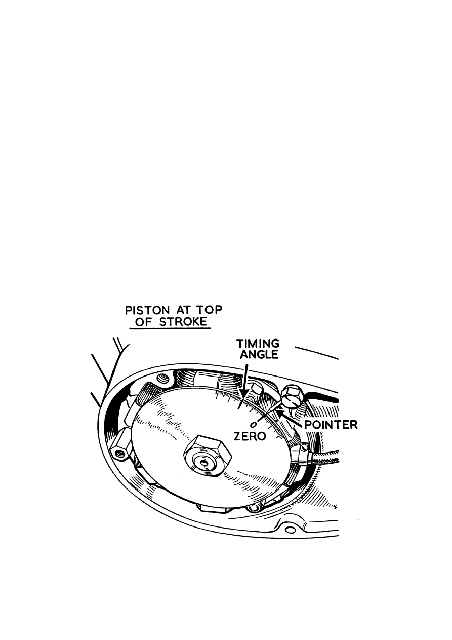
owner is ever likely to carry out. To check the actual timing ignition, it will first be
necessary to remove the primary chain cover and then adapt a degree plate to the
engine main shaft, accompanied by a suitable pointer connected to a convenient stud,
as illustrated in Fig. 3. Next, determine the top dead centre position of the piston.
Rotation of the engine through several degrees near this position produces a very
small movement of the piston which is difficult to detect. If the cylinder head is
removed a straight-edge can be laid across the top of the barrel to act as a stop for the
piston.
Bring the piston gently up to the straight edge by rotating the engine as far as it
will so, first in one direction and then in the opposite direction. If degree plate
readings are taken in each position, the point mid-way between them is easy to
calculate and this will be an accurate top dead centre. Adjust the timing disc until the
zero mark corresponds with the pointer.
From this position rotate the engine BACKWARDS by 18-degrees and check that
with the piston in its new position, the contact breaker points are just separating (not
more than ·002 in. open). If they are open by more than this amount the timing is
advanced excessively and vice versa.
It is essential to ensure a correct contact points gap before setting the ignition
timing.
Fig. 3. Timing the engine with a degree plate
14

DECARBONISATION
Decarbonising is extremely simple and should be carried out at regular intervals of
about three thousand miles (5,000 km.) if consistent results are to be expected. The
symptoms indicating an excessive deposit of carbon are undue roughness of the
engine and a tendency to pink under load, erratic running with excessive four and
eight stroking, and an appreciable falling off in power. This latter item is particularly
noticeable when the exhaust port becomes fouled with carbon as it causes an
obstruction to the free escape of the exhaust gas, and interferes with the correct
scavenging of the cylinder which is so necessary for the efficient transfer of
combustible mixture from the crankcase.
Silencer
The silencer is fitted with a detachable end cap held in position by a single nut.
When this is unscrewed the cap can be removed and the internal baffles which are
mounted on a central tube, can be withdrawn for cleaning. This should be carried out
at the same time as decarbonisation of the engine. When reassembling, make sure
that the copper sealing ring is in position before replacing the end cap, and that the
plain washer and the spring washer are replaced on the stud before tightening the nut.
Removal of Cylinder
First turn off the petrol and detach the petrol pipe at the carburetter. The pipe is
affixed to the petrol tap union and should not be disturbed. Next, disconnect the air
cleaner hose and remove the carburetter from the cylinder flange still attached to its
cables and tie back out of the way. The exhaust pipe must also be disconnected by
releasing the union nut at the front of the cylinder barrel using a “C” spanner for this
operation. If this nut should prove unduly obstinate, a few drops of penetrating oil
should be applied to the threaded portion immediately above the nut and a little time
should be allowed for this to act before attempting to unscrew the nut. Remove the
whole exhaust system. Disconnect the high tension lead from the sparking plug and
unscrew the latter.
The cylinder head and barrel are attached to the crankcase by means of four long
studs, and when the four nuts on the top of the cylinder head are removed, the head
and then the barrel can easily be lifted clear. Removal of the cylinder barrel is greatly
facilitated if the two petrol tank front locking bolts are unscrewed so that the tank can
be raised slightly and it will also be found beneficial to slacken the two crankcase
joint screws immediately below the bottom fin on the barrel. Take care when
removing the barrel to support the piston as it emerges from the end of the bore to
protect it from damage as it comes clear.
Removal of Cylinder (Bushman)
Due to the high ground clearance provided on these models, it is necessary to remove
the petrol tank prior to removal of the cylinder. The tank is bolted to the frame at
front and rear connections and the tap and pipe can be left in position on the tank.
15

Piston
Place the cylinder head and barrel on one side on a bench and examine the piston.
It should not be necessary to remove this from the connecting rod, but if it should be
desired to do this for any reason, first remove the circlip from one end of the gudgeon
pin using a pair of pointed nose pliers or some suitable instrument to lever the circlip
out. Then, with the aid of a suitable extractor, withdraw the gudgeon pin. If it is too
tight to move, it can be released by warming the piston by means of a rag soaked in
hot water and wrung out. Application of this rag will cause the aluminium alloy of
the piston to expand more than the steel gudgeon pin, thus releasing the latter which
can then be freely removed. Be careful not to damage the needle rollers comprising
the gudgeon pin bearing in the connecting rod.
Scrape off any carbon which has accumulated on the crown of the piston, taking
care not to damage the relatively soft surface of the metal itself, and after removing
all the carbon, wipe clean with an oily rag.
Piston Rings
Now examine the piston rings noting that these are located in their grooves by
means of pegs which engage in the piston ring gaps. If in good condition the rings
will be found to present a uniformly smooth metallic surface over their entire
peripheries, and if they are in this condition and obviously have a certain amount of
“springiness” as evidenced by the fact that their free gap is considerably greater than
the closed gap when in the bore, they should not be disturbed. If, on the other hand,
the rings show signs of heat as evidenced by brown or more highly discoloured
patches, they should be replaced by new rings, and in this case particular attention
should be paid to the fit of the ends of the rings on their locating pegs in the piston
ring grooves, and they should also be checked in the bore to ensure that they have an
adequate gap. First place the ring in the cylinder bore in a position where it is clear
of the ports making certain that it is parallel with the bore by inserting the piston with
its skirt against the ring. Examine the gap which should be not less than specified
(see Technical Data, page 5). Having satisfied yourself on this point, place the ring
in its groove on the piston and make certain that it is free without perceptible up and
down play. If it is not free and the groove itself is clean, rub the ring down on a piece
of fine emery cloth laid on a flat surface, using a rotary motion of the arm to ensure
uniform pressure on the ring. As soon as ring is found to be free in its groove, wipe it
absolutely clean and fit it into position.
Check also that there is sufficient clearance between the inner portion of the gap
and the locating peg in the groove. Do this by closing the ring in its groove by finger
pressure until there is no gap, thus showing that there is clearance at the peg
underneath. If the gap will not close, indicating that the steps are binding on the peg,
ease the steps gently with a smooth file. If the piston has been removed from the
connecting rod refit it, first putting a smear of oil on the gudgeon pin, not forgetting a
new circlip to replace the one which was removed.
The piston must be replaced in its original position—i.e., with piston ring gaps
towards the front.
Then put a piece of clean rag over the piston and crankcase mouth and turn your
attention to the cylinder barrel and head.
16

Cylinder Head and Barrel
Remove all carbon deposit from the cylinder head, bearing in mind again that the
aluminium is soft and easily damaged if the decarbonising tool is carelessly applied,
and carefully wipe clean to ensure the removal of all loose particles. Most of the
carbon deposit likely to have accumulated in the cylinder will be in the exhaust port,
and cleanliness at this point is most important as explained earlier. Scrape this out
carefully, taking care not to let the tool slip into the bore and damage the surface of
the latter. Examine the transfer and inlet ports for the presence of carbon, although
this is unlikely to be heavy, and finally wipe the ports and the cylinder bore
absolutely clean.
Big end Bearing
While the cylinder is off, it is as well to test the big-end bearing for wear. This is
done by taking hold of the connecting rod stem and pulling it upwards until the crank
is at the top of its stroke. Then, holding it in this position, try gently but firmly to
pull and push the connecting rod in the direction of its travel in order to feel whether
there is any play. If the big-end is in a sound condition there should be no play in this
direction although it may be possible to rock the rod sideways, i.e. at right angles to
the axis of the machine. If vertical play is perceptible in the big-end and you do not
feel qualified to decide whether the amount in evidence is permissible or not, you
should seek expert advice. This point is not likely to give trouble, however, provided
that the machine has been carefully used and adequately lubricated, for the big-end
bearing is of ample dimensions for the work it has to do. But if for any reason the
big-end bearing has deteriorated as the result of neglect or abuse, it should be
replaced and unless you have the necessary experience and facilities for this class of
work it is preferable to have it done by an expert repairer.
Re-assembly
Before attempting to replace the cylinder barrel over the piston, smear the former
generously with engine oil and then place it over the piston, carefully manipulating
the rings into the end of the bore and seeing that they enter freely without the
application of force. As soon as the cylinder barrel is in position, replace the cylinder
head and put the washers and nuts on the four holding down bolts. Tighten the nuts
in diagonal order so as to avoid distortion and, if a torque spanner is being used, it
should be set to 10 lb. ft.
Examine the sparking plug and replace if sound. Check the rubber sealing ring on
the carburetter flange, replacing if damaged. Finally reconnect the exhaust pipe,
carburetter, and petrol pipe.
Sparking Plug
The sparking plug is of great importance to satisfactory engine performance, and it
is necessary that it should be the correct type and in good condition. Champion type
N4 is recommended.
The condition of a sparking plus can be helpful in determining the condition and
tune of an engine, and it is recommended that the plug be removed from time to time
for examination.
17
A plug running at the correct temperature in a healthy engine will be indicated by
blackish or greyish-tan deposits on the end of the plug body and earth electrode. The
firing end of the insulator will vary from a very light tan to a darkish brown.
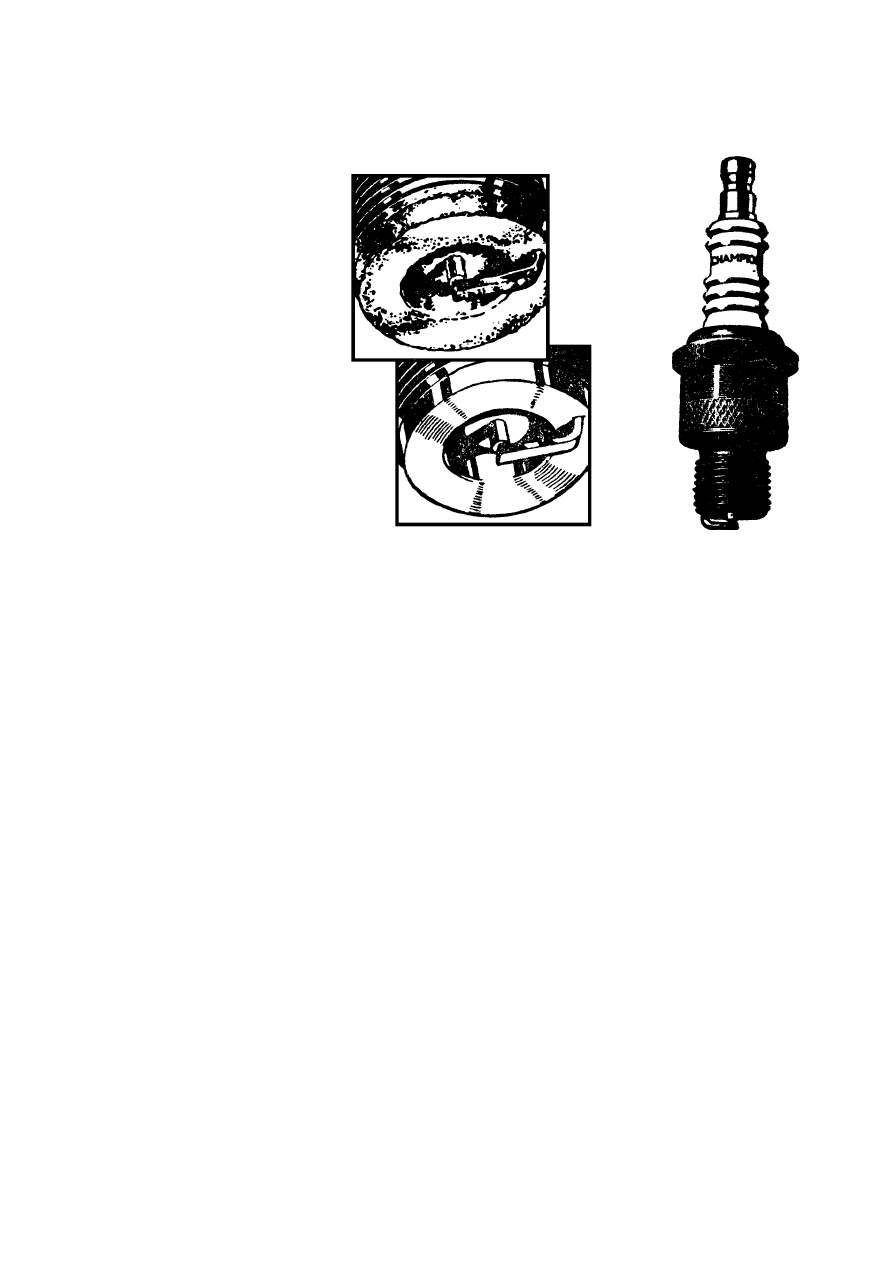
Fig. 4. The sparking plug
A sooty deposit on the firing end of the plus is generally an indication of an over-
rich mixture, whereas a light grey deposit on the end of the plus and a white-ish
appearance on the firing end of the insulator may indicate a lean mixture. If the
carburation appears correct, but the plug insulator at the firing end is black with
carbon or oily deposit, this is generally an indication that the grade of plug is too
cold.
The plug should be cleaned on an abrasive blast machine and afterwards the
sparking surfaces of the electrodes on standard type plugs should be dressed with a
fine file in order to restore clean, flat, parallel faces. It is most important that the gap
should be re-set to specification, ·025 ins. Gap adjustment should be made by
bending the side wire. The threads of the plug, and the gasket seat, should be wiped
clean before refitting the plug to the engine. The upper portion of the insulator
should also be wiped clean after fitting, and prior to connecting the H.T. cable. It is
good practice to wipe periodically the top of the insulator with a clean cloth in order
to remove any accumulation of grime or dust etc., as such deposits can be conductive,
and result in poor plug performance.
The special non-detachable steel gaskets fitted to Champion standard sparking
plugs are designed to last the life of the plug.
When refitting the plug, screw in as far as possible by hand, and then use a box
spanner for final tightening, to avoid possibility of damage to the insulator. An
adjustable spanner should not be used.
THE AMAL CARBURETTER
The carburetter is of simple and robust construction and the only attention that may
be required is adjustment of the pilot jet and throttle stop.
18
(Above)—Fouled
with burnt oil or soot
(Below)—Correct

An exploded view of the carburetter is shown in Fig. 5. Opening the twist grip
throttle control raises the throttle slide thus controlling the supply of air to the engine.
The tapered needle controlling the supply of fuel is attached to the throttle slide so
that a balanced mixture is always provided. The needle has a number of notches at its
upper end and it is secured in the throttle slide by the spring and by the circlip which
locates in one of the notches. The throttle valve size and the needle position are
carefully set before despatch from the factory and no alteration to these settings is
necessary or desirable.
Mixture control at low speeds is by the pilot jet which has an adjustable air supply.
An adjustable throttle stop is also provided to regulate the slow running speed. Both
throttle stop and pilot air screws are fitted with “0” rings to retain the adjustment and
if the screws are taken out, the rings must be carefully preserved.
To achieve good petrol economy accurate adjustment of the pilot jet and throttle
stop is important. These are adjusted before the machine leaves the Works, but the
best setting may vary slightly to suit rider’s requirements or particular localities. The
adjustment should be made with the engine warm.
Screwing in the pilot air screw restricts the air supply thus giving a richer mixture,
and unscrewing it weakens the mixture. The best way to adjust is to screw in the
pilot air screw until the mixture is obviously too rich and the engine starts to run
irregularly, and then unscrew the adjuster until the engine runs evenly. If it is
unscrewed too far the engine may cut-out or may spit back through the carburetter
when the throttle is opened. When the proper adjustment has been determined, the
engine may be running too fast and in this case the throttle stop should be unscrewed.
If considerable alteration to the throttle stop has been made, the pilot air screw should
be re-adjusted.
In the case of blockage, the jets are exposed after removal of the float bowl, the
main jet requiring a suitable spanner for removal and a small screwdriver for the pilot
jet. Removal of the float bowl will be simplified if the carburetter is first detached
from the cylinder barrel, when the screws securing the bowl become readily
accessible.
No advantage will be gained by altering the jet sizes from those recommended.
Carburetter Air Control
The air slide in the carburetter is cable-controlled from a lever on the right
handlebar (Fig. 1). To close the air slide, the lever must be pushed away from the
rider (anticlockwise rotation) thus enriching the mixture. The air slide is opened by
turning the lever as far as possible in a clockwise direction and it should be kept in
this position at all times except when starting from cold.
Special Note.—New riders especially are advised to study the action of the air
control and to treat this device with respect. It should only be used momentarily
when starting from cold and even then only when necessary. Immediately the engine
fires it should be opened. This point is of special importance in the event of difficult
starting, possibly due to some other circumstance such as a defective sparking plug,
because repeated operation of the starter pedal with the air control closed results in
the accumulation of liquid petrol in the crankcase and when this occurs, starting is
quite impossible until it is drained away by the removal of the crankcase drain plug,
which is the smaller of the two plugs under the crankcase.
19

Air Cleaner (Supreme and Sports models)
This is concealed behind the right side panel which must be removed first. The air
cleaner element is retained by a flexible strap and, following its removal, the element
can be withdrawn. It should be cleaned at intervals of about 2,000 miles. Wash the
filter element thoroughly in petrol, allow to dry, and re-assemble. Failure to clean the
filter regularly may cause it to become partially choked with a consequent
deterioration in petrol consumption and performance.
Air Cleaner (Bushman model)
The air cleaner is mounted below the seat and must be taken out for cleaning.
Remove the seat and then the right side panel, when the filter fixing bolts and hose
dips become accessible, and the complete filter assembly can be withdrawn.
Removal of the clip screws allows the unit to be dismantled and the filtering
element to be extracted.
The element is made of a specially treated paper and should receive attention at a
maximum mileage of 1,000—more frequently in exceptionally dusty climates. It is
preferable for the element to be replaced regularly but where this is not possible, it
should be well brushed to remove all traces of dust and the interior of the container
treated similarly.
Failure to clean the filter regularly may cause it to become partially choked, with a
consequent deterioration in petrol consumption and performance.
20
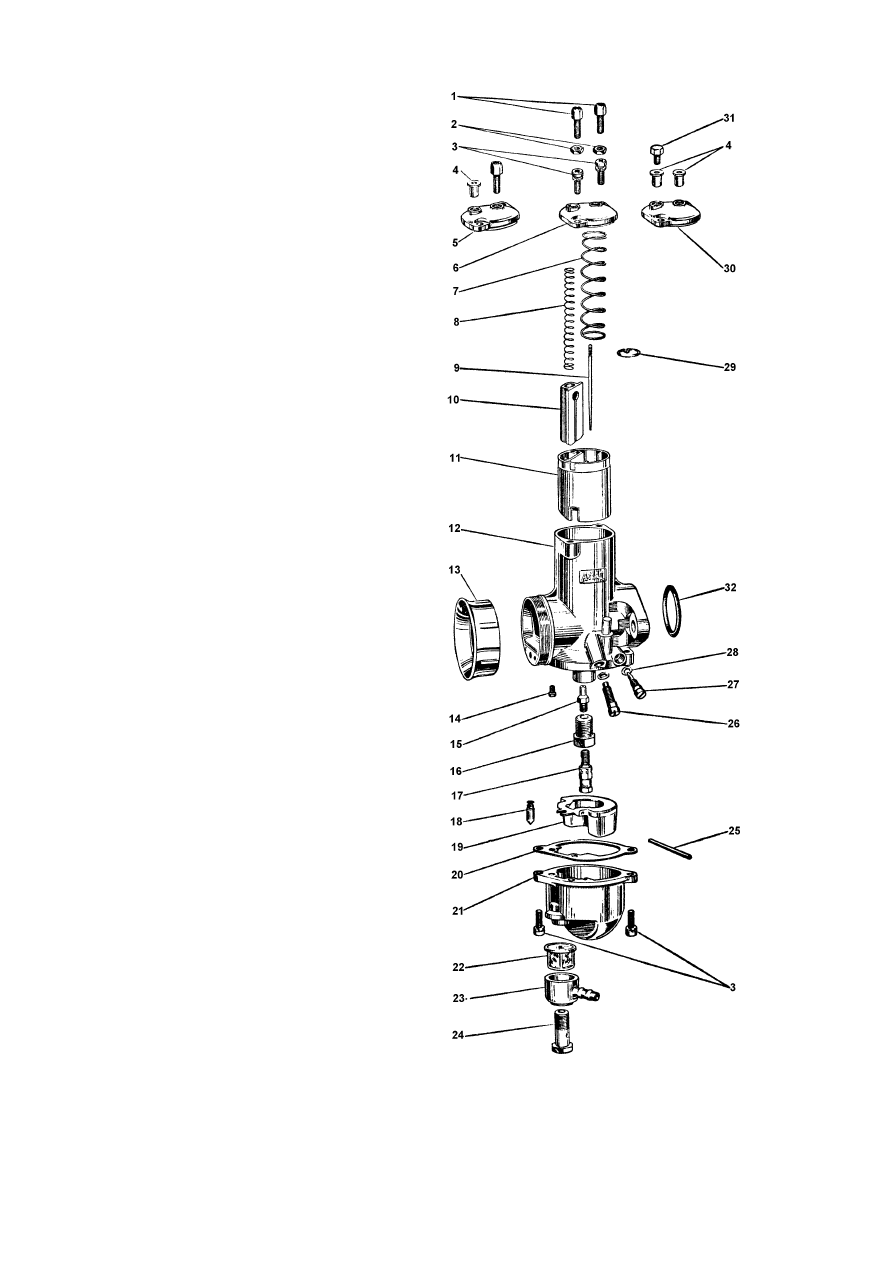
9. NEEDLE
10. AIR SLIDE
11. THROTTLE SLIDE
14. PILOT JET
15. NEEDLE JET
16. NEEDLE JET HOLDER
17. MAIN JET
18. FLOAT NEEDLE
19. FLOAT
26. THROTTLE STOP SCREW
27. PILOT AIR SCREW
Fig. 5. The Amal concentric carburetter
21

Front Forks
Castrolite
Shell X100-20
Esso 20W/30
Mobiloil Arctic
Energol SAE 20
Havoline SAE 20W
Greas
e Points
Castrolease L.M.
Shell Retinax A
Esso Multi Purpose
Greas
e H
Mobilgrease MP
Energrease L2
Marfak
Multi purpose 2
Gearbox
Castrol XXL
Shell X-100 40
Esso Extra
Motor Oil 40/50
Mobiloil BB
Energol SAE 40
Havoline SAE 40
Oil
Engine
Castrol Two-Stroke Oil
2T Two-Stroke Oil
Esso Two-Stroke (2T)
Motor Oil
MobilMix TT
Energol Two-Stroke Oil
Motor Oil 2T
LIST OF RECOMM
ENDED LUBRI
CANTS
All the engine oils listed below are self-m
ixing and m
ust be used in the proportion
of 1 part oil to 24 parts petrol (i.e. 4% m
ixture), given by the following:—
3½ filler cap measures of oil to 1 gallon of petrol.
If non self-m
ixing two-st
roke oil is used, (or alternativ
ely, an S.A.E. 40 grade of oil), the proporti
on is 1 part
oil to 32 parts petrol (i.e. 3% m
ixture)
given by 2½ m
easures to 1 gallon petrol.
Note: For running-in purposes on
e extra measure may be added.
Brand
Castrol
Shell
Esso
Mobil
BP
Regent
Important Note: Self-mixing oils are specially prepared
for use in tw
o-strok
e
engines and their use is strongly
preferred.
22
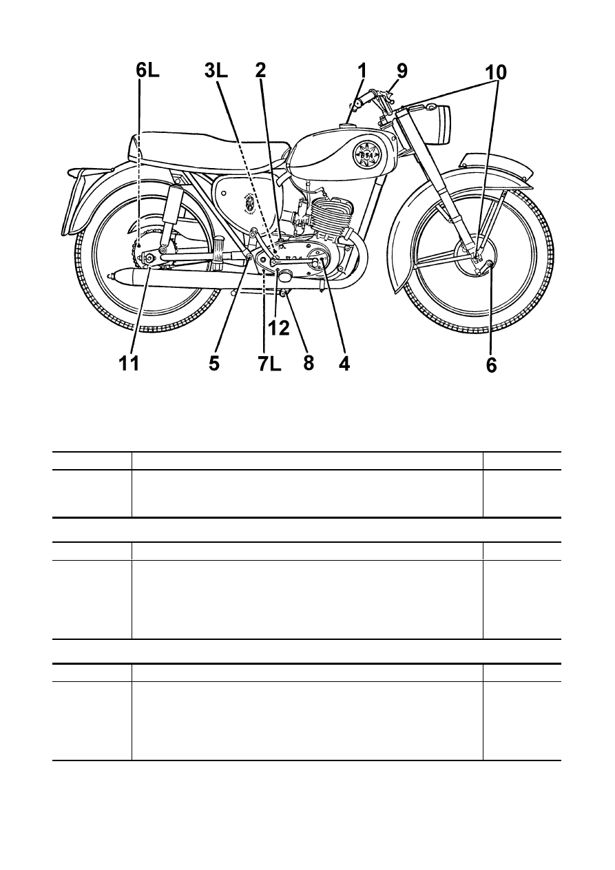
KEY LUBRICATION POINTS
(L indicates left hand side, remained right hand side or both sides).
The illustration shows the Bantam Supreme.
Lubrication details for the other models are the same.
OIL. (See Chart page 22)
No.
Item
Page
1
2, 12
10
Petroil Mixture
. .
. .
. .
. .
. .
. .
Gearbox and Primary Drive
. .
. .
. .
. .
Front Forks . .
. .
. .
. .
. .
. .
. .
12 & 22
12 & 26
12 & 28
GREASE
No.
Part
Page
3
4
5
6
11
Clutch Control
. .
. .
. .
. .
. .
. .
Contact Breaker Cam Pad
. .
. .
. .
. .
Swinging Fork Pivot
. .
. .
. .
. .
. .
Brake Cams . .
. .
. .
. .
. .
. .
. .
Speedometer drive . .
. .
. .
. .
. .
. .
21 & 25
12 & 13
12 & 30
12
12 & 27
A FEW DROPS OF ENGINE OIL
No.
Part
Page
7
8
9
—
Brake Pedal . .
. .
. .
. .
. .
. .
. .
Central Stand
. .
. .
. .
. .
. .
. .
Handlebar Levers . .
. .
. .
. .
. .
. .
Control Joints and exposed cables
. .
. .
. .
(not illustrated)
12
12
12
12
23
TRANSMISSION
Front Chain
The front chain runs on short fixed centres and adjustment is neither required nor
provided.
The chain will run for many thousands of miles before examination is required.
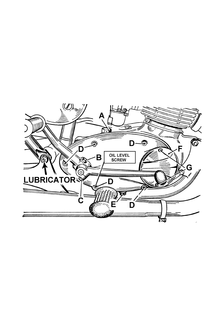
This operation involves the removal of the primary chain cover (Fig. 6), after the
starter and gear change pedals, both of which are mounted on splines and locked by
pinch bolts “B” and “C” respectively, have been removed, together with the five
securing screws “D”. The normal up and down play on the front chain is up to ⅜ in.
(1 cm.) and the maximum permissible, indicating that the chain is unduly worn and
requires replacement, is about ¾ in. (2 cm.).
Primary Chain Lubrication
This has a common oil supply with the gearbox and therefore does not require
separate attention, beyond the instructions for the gearbox.
Fig. 6. Primary drive
The Bantam Supreme is shown, but details apply to all models.
Care of the Rear Chain
It is a good plan periodically to remove the rear chain, clean it thoroughly in petrol
or paraffin, and then gently warm in a mixture of grease and graphite. When cool
wipe off excess grease, clean sprockets and replace chain. Remember when
replacing the chain, which is fitted with a detachable connecting link, that the spring
fastener must always be put on with the closed end pointing in the direction of travel
of the chain (i.e. on the lower run of the chain, the closed end should be rearward).
24
Rear Chain Adjustment
Adjustment of the rear chain involves moving the rear wheel and is described on
page 27.
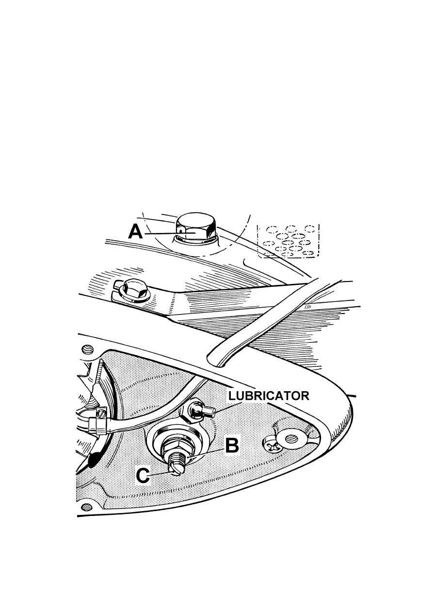
Clutch Control
The clutch adjustment will be found at the left-hand end of the gearbox mainshaft
(see Fig. 7) and it consists of an adjusting pin C screwed into the clutch withdrawal
sleeve and a locknut B to secure it in position. These items are accessible through an
aperture in the outer cover, after removal of the rubber cap, or by removal of the
complete outer cover. The adjusting pin presses against the clutch withdrawal rod
with a steel ball interposed and the withdrawal mechanism must at all times be so
adjusted that there is a slight amount of play between the pin, the steel ball, and the
operating rod, in order to ensure that the clutch springs may exert their full pressure
on the driving and driven plates. If there is not sufficient play there will be a
tendency for the clutch to slip continually owing to reduced spring pressure, and this
in turn will cause over-heating and serious damage to the clutch itself.
Fig. 7. Clutch control adjustment, with outer cover removed.
25

If the play becomes excessive, difficulty will be experienced in changing gear, as
the clutch may not fully disengage, in which case the control should be adjusted as
explained below.
To adjust, release the locknut and holding it with a spanner unscrew the adjusting
pin with a screwdriver one or two turns. Still holding the locknut with a spanner,
screw the adjusting pin gently in until it is felt to meet some resistance. Then
unscrew it half-a-turn and holding it in this position retighten the locknut. If the
adjustment is correctly made in this manner, it will be found that there is a small
amount of free play at the clutch lever on the left handlebar before this is felt to take
up the spring pressure during the action of declutching.
The clutch operating mechanism should be greased at regular intervals to maintain it
in good condition (see Page 12).
Clutch Dismantling
Before dismantling the clutch, the primary chain case cover must be removed as
described under Front Chain on page 24. The clutch springs must be compressed by
pressing the outer plate inwards until the circlip retaining the spring pressure plate
can be removed. Care must be taken to see that the springs are properly compressed
as damage may result if they are released suddenly and the job is best accomplished
with the aid of special clutch spring compressing tool 61-3191. When the spring
pressure plate is removed the four plates carrying friction pads can be withdrawn,
together with their mating plain plates. If the pads are burnt or otherwise damaged,
the plates should be replaced.
Gearbox
The gearbox, although built in unit construction with the engine, is self contained
as regards lubrication. An engine oil of S.A.E. 40 grade (page 22) is used for
lubricating the gears and primary drive, but self-mixing engine oils must not be used.
To change the oil in the gearbox, remove drain plug E (Fig. 6) at the bottom of the
gearbox and drain out the old oil. Wash out the gearbox with flushing oil and refill
with new oil through filler hole A (Fig. 7) to the appropriate level.
The correct level is given by the screw D (Fig. 6) situated on the primary drive cover
behind the footrest. The screw is painted red for ease of identification and must be
removed when refilling the gearbox. Replenish until oil flows from the level screw
hole and when any surplus oil has drained off, replace the screw firmly, followed by
the filler plug.
WHEELS
Hubs
These are fitted with ball journal bearings, and no adjustment is either provided or
required. The bearings are packed with grease during assembly and this should last
until the machine needs a complete overhaul.
Speedometer gearbox
The unit requires no attention apart from lubrication at intervals (see page 12)
Grease with two applications from a hand grease gun only.
26
Front Wheel Removal (Bantam Supreme)
Disconnect the brake cable at the lever on the brake cover plate and then remove
the nut securing the cover plate to the fork leg. Remove the caps at the bottom of the
fork legs, supporting the wheel as this is being done and withdraw the wheel. When
replacing make sure the spindle ends are level with the end faces of the caps and that
the cover plate nut is securely tightened.
Bantam Sports and Bushman
Wheel removal is similar to that for the Supreme model except that the brake cover
plate is anchored by a tongue on the fork leg. Make sure that the tongue and the
slotted brake plate are properly engaged when the wheel is replaced.
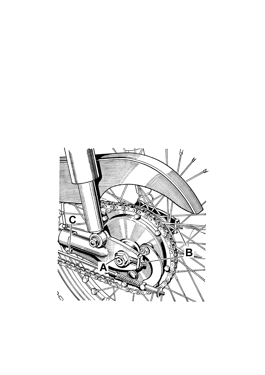
Rear Wheel Removal
Disconnect the speedometer cable from the drive unit and unscrew the adjuster
from the brake rod. The rear chain should be disconnected at its spring link and
unwound from the rear wheel sprocket. It is advisable to leave the chain in position
on the gearbox sprocket. It will also be necessary to uncouple the brake plate arm
from the swinging fork at C (Fig. 8). Finally, slacken the spindle nuts sufficiently to
allow the wheel to be withdrawn. During re-assembly make sure that the brake plate
bolt is securely tightened. Check also that the chain adjusters are firmly against the
fork ends.
Fig. 8. Rear Chain Adjustment
The illustration id for the Supreme and Bushman models. The Sports model is similar
except for full width hub, and the method of adjustment is the same for all models.
27

Rear Chain
The rear chain is adjusted by means of draw bolts at the fork ends at the back of
the wheel spindle. First slacken off the brake adjuster, as the brake rod may prevent
free movement of the wheel. Next, loosen the nut on the inside of the brake plate arm
at C, to allow the slotted arm to accommodate itself to a new position when the wheel
is moved. It is not necessary to disturb the speedometer drive unit. Slacken off the
spindle nuts A (Fig. 8) and tighten the adjusting nuts B until the chain tension is
correct.
The chain should be adjusted with the machine on its stand, i.e., with the rear
wheel in its lowest position in the rear suspension. The adjustment is correct when
the total up and down movement in the centre of the chain run at its tightest point is
¾ in.
Make sure that the adjusters are firmly against the fork ends when checking, and
also that the adjustment is equal on both sides of the wheel so that the latter is in
correct alignment in the frame. This can be done either by glancing along the line of
both wheels when the front wheel is set straight, or by means of a long straight-edge
or the edge of a plank placed along the sides of the wheels. The straight-edge should
touch the wall of each tyre in two places.
After adjusting, do not forget to retighten nuts A and C.
Brakes
The brakes should be adjusted whenever the handlever or foot pedal movement has
become excessive. The shoes should be just clear of the drum when the brake is off,
but close enough for immediate contact when the brake is applied. The brakes must
not be adjusted so closely however, that they are continually in contact with the
drum, otherwise excessive heat may be generated resulting in deterioration of braking
efficiency.
In the case of the rear brake a sleeve nut on the brake rod effects any adjustment
necessary, and a few turns are all that are required to improve braking efficiency.
The front brake is adjusted by means of the knurled ring nut on the cable stop at the
lower end of the forks.
STEERING AND SUSPENSION
Under normal conditions the only servicing which the front forks require is
occasional renewal of the oil. The need for this may be indicated by excessive
movement of the forks, but it should only be necessary after considerable mileage.
Bantam Supreme
Prise out the cap on the top of the fork leg by means of the small hole provided for
the purpose, and with the aid of a tubular spanner unscrew the small nut thus
exposed. Then remove the large nut which carried the cap. Disconnect the
mudguard stay at the lower end of the fork leg, and unscrew the stud. Allow all the
oil to drain out, then apply the front brake and depress the forks a few times to drive
out any oil remaining in the system. Replace the drain stud and fibre washer.
Add ⅛ pint of an S.A.E. 20 oil to each leg (see lubrication list, page 22) and
replace the top nuts and cap.
Bantam Sports and Bushman
The procedure for draining and re-filling the forks is as above except that the filler
is a single cap nut on top of the fork leg and a drain screw is provided at the bottom
of the fork sliding member, near to the wheel spindle.
1
/
6
pint of an S.A.E. 20 oil is required in each leg.
28
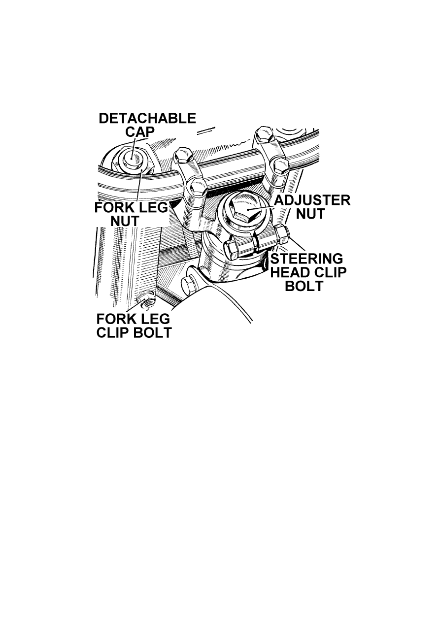
Steering Head Adjustment (All models)
It is first necessary to raise the front wheel clear of the ground—this can best be
done by lifting the machine on its stand and putting some small weight on the rear of
the machine causing the rear wheel to rest on the ground. Test for play by grasping
the fork legs and attempting to push them backwards and forwards. If play can be
detected the head bearing requires adjustment.
Fig. 9. Front fork and steering head (Bantam Supreme)
Slacken the clip bolt on each fork leg below the lamp so that the bottom yoke is
free to take up a new position.
Release the steering head clip bolt Fig. 9, and tighten adjuster nut until any
slackness has been taken up. Do not over-tighten or steering will be stiff and the ball
races may be damaged. Finally, retighten the steering head clip bolt followed by
those on the bottom yoke. To check, hold the handlebars lightly and move them
round slowly, when the steering should be free and rotate smoothly.
Rear Suspension
The two suspension units each comprise a telescopic damper unit and a totally
enclosed coil spring. The hydraulic dampers require no attention whatsoever. They
are sealed during manufacture and if they suffer damage or become ineffective they
must be replaced.
The complete suspension units can be removed from the frame after detaching the
pivot bolts at the top and the retaining nuts at the bottom.
The swinging fork pivot is provided with grease nipples and should be thoroughly
lubricated every 1,000 miles.
29

THE ELECTRICAL SYSTEM
(Supreme and Sports models)
The lighting and ignition systems are fed by a simple 6 pole alternator generating
set which supplies current through a metal plate rectifier to the battery, this then
feeding the ignition system, lights, horn, etc., through the appropriate switches.
The alternator stator carries 6 coils which are wired in three sets of two series-
connected coils. With the lighting switch in the “Off” and “Low” positions, two coils
only are in operation, but when the headlight is in use or the emergency ignition is
selected, all six coils are in circuit. Regulation of the charging rate is achieved by
linking pairs of alternator coils according to the positions of the head light and
ignition switches.
The alternating current supplied by the generator is converted to direct current by
means of the rectifier, which is of the full wave bridge connected type.
The main connections in the system are made by socket connectors to the lighting
and ignition switches, and by individual insulated snap connectors in the wiring.
These connectors are not intended as plugs and sockets for frequent manipulation and
are only for use when testing or fault finding. It is extremely important that they
should be making perfect connection, as should all other connection points
throughout the system.
Emergency Starting
The alternator equipment includes an emergency starting system which, when the
ignition switch is moved to the emergency position, connects all six coils together
and, providing that the lighting switch is in the “Off” position, gives full output in
order to restore the voltage of a discharged battery. Under these conditions an
immediate start can be made. The maximum charging current in the emergency
position is very high because there is no reduction in current due to the lighting
system, and the engine should not be run with the switch in this position for more
than 10-15 minutes.
Battery
At weekly intervals, take off the left side panel to expose the battery. Release its
wire retaining clip, take off the lid and withdraw the battery through the aperture.
Remove the filler plugs from each of the cells and examine the level of the
electrolyte. If necessary, add sufficient distilled water to bring the level of the
electrolyte up to the top of the separators. Do not use tap water and do not use a
naked light when examining the conditions of the cells.
The condition of the battery should occasionally be checked by taking hydrometer
readings of the specific gravity of the electrolyte. If distilled water has been added a
reading should not be taken until after the machine has been used.
Never leave the battery in a discharged condition as it will suffer permanent
damage. When standing idle, the battery should be given a freshening charge at least
once a month. Twelve hours at ּ8 ampere is recommended. Keep the top of the
battery clean and smear the terminals with vaseline to prevent corrosion.
30

A positive earth wiring system is employed. Make sure that the battery is
connected correctly, i.e. with the positive (
+
) side of the battery connected to earth.
The coloured lead must be connected to the battery NEGATIVE (
–
) terminal, and
the translucent (earth) lead to the battery POSITIVE (
+
) terminal.
Generator
The generator consists of two assemblies, namely, the magnetic rotor, and the
stator which carries the six low tension coils. The rotor carries six laminated
magnetic pole pieces; it is self-keeping and may be separated from the stator without
any loss of magnetism.
The set requires practically no maintenance, but if the stator is removed for
inspection or replacement at any time, the soldered connections which are visible
should be checked to ensure that none is touching another, nor touching earth.
Before replacing, ensure that the pole faces are free from metallic dust and that the
main cable is clear of all moving parts.
Running without a Battery
It is not advisable to run without a battery in circuit, because if the lights should be
inadvertently switched on whilst the engine is running, all bulbs will immediately
fuse. Furthermore, there is serious risk of burning out the rectifier.
Rectifier
Provided that the leads are securely attached to the rectifier, and the rectifier casing
is kept clean, no service or adjustment should be required. Since the rectifier is air-
cooled it is important to ensure that the air-flow, created whilst the machine is in
motion, is not obstructed.
Contact Breaker Unit
Cleaning, lubrication, and gap setting of the contact breaker points are fully
described on page 12.
Horn
If necessary the horn may be adjusted by means of the small screw in the back of
the body. A slight turn to left or right while depressing the horn button will enable
the best note to be obtained.
Headlight
The front, together with the reflector and bulb assembly, is secured to the main
casing by means of a slotted screw above the lamp rim.
To replace a bulb therefore, it is only necessary to loosen the screw until the rim
can be removed. To replace the double filament bulb, press the bulb retainer inwards
and turn slightly anti-clockwise, when it can be lifted off and the bulb withdrawn. A
replacement bulb automatically provides correct relationship of the filaments.
The best way of checking the setting of the lamp is to stand the motor cycle in
front of a light coloured wall at a distance of about 25 feet. If necessary, slacken the
two screws on the nacelle rim or lamp side according to model, and move the lamp
until, with the main driving light switched on, the beam is projected straight ahead
and parallel with the ground. With the lamp in this position, the height of the beam
centre on the wall should be the same as the height of the centre of the headlamp
from the ground.
31

Rear Lamp
A single bulb is used for both stop and rear light purposes.
The transparent red plastic portion of the lamp can be removed by unscrewing the
two countersunk screws.
Stop Light Switch
This is operated by the brake rod through a spring. It is desirable to see that any
mud or grease is periodically cleared away from the switch, and the operating
mechanism should be oiled occasionally with thin oil.
Wiring Diagram
A diagram of the electrical circuit appears on page 34. The insulation of the wires
is individually coloured and these colours are indicated on the diagram.
The wiring is connected by means of snap connectors at various convenient places
on the machine and it is desirable occasionally to check it over and make certain that
these connectors are tight.
BULB TYPES
Headlamp (main bulb)
Headlamp (pilot bulb)
Rear-Stop light bulb
Speedometer bulb
6 volt, 30/24 watt. pre-focus.
6 volt, 3 watt. M.E.S.
6 volt, 6/18 watt. S.B.C.
6 volt, ·6 watt. B.A. 7S Lug Cap.
THE ELECTRICAL SYSTEM
(Bushman model)
The lighting and ignition systems are fed by a simple 6-pole alternator generating
set supplying the ignition system, which incorporates an ignition coil designed
especially to operate on the energy transfer principle, and also the lights and horn
which are operated through the switches mounted on the headlight body or handlebar
respectively.
The alternator carries six coils, of which two feed the lights, two more feed the
horn and the remaining two individually serve the external ignition coil and the stop-
light.
The main connections in this system are made by socket connectors to the lighting
switch and by individual insulated snap connectors in the wiring. The connectors are
not intended as plugs and sockets for frequent manipulation and are only for use
when testing or fault-finding. It is extremely important that they should be making
perfect connection, as should all other connection points throughout the system.
Generator
The generator consists of two assemblies, namely, the magnetic rotor, and the
stator which carries the six low tension coils. The rotor carries six laminated
magnetic pole pieces; it is self-keeping and may be separated from the stator without
loss of magnetism.
32

The set requires practically no maintenance, but if the stator is removed for
inspection or replacement at any time, the soldered connections which are visible
should be checked to ensure that none is touching another, or touching earth.
Before replacing, ensure that the pole faces are free from metallic dust and that the
main cable is clear of all the moving parts.
Contact Breaker Unit
Cleaning, lubrication, and gap setting of the contact breaker points are fully
described on Page 12.
Head Light
The front, together with the reflector and bulb assembly, is secured to the main
casing by means of a slotted screw below the lamp rim. To replace a bulb, therefore,
disengage and withdraw the front rim and light unit assembly, removing the lower
edge first.
To replace the double filament bulb, press the bulb retainer inwards, and turn
slightly anti-clockwise, when it can be lifted off and the bulb withdrawn.
Replacement bulb automatically provides correct relationship of the filaments.
The best way of checking the setting of the lamp is to stand the motor cycle in
front of a light-coloured wall at a distance of about 25 ft. If necessary, slacken the
two screws on the lamp side, and move the lamp until, with the main driving light
switched on, the beam is projected straight ahead and parallel with the ground. With
the lamp in this position, the height of the beam centre on the wall should be the same
as the height of the centre of the lamp from the ground.
Rear Lamp
A single bulb is used for both stop and rear light purposes. The transparent red
plastic portion of the lamp can be removed by unscrewing the two countersunk
screws.
Stop Light Switch
This is operated by the brake rod through a spring. It is desirable to see that any
mud or grease is periodically cleared away from the switch, and the operating
mechanism should be occasionally lubricated with thin oil. Check also that the cable
sleeve at the switch connection is in good order.
Wiring Diagram
A diagram of the electrical circuit appears on page 35. The insulation of the wires
is individually coloured and these colours are indicated on the diagram.
The wiring is connected by means of snap connectors at various convenient places
on the machine and it is desirable occasionally to check it over and make certain that
these connectors are tight.
BULB TYPES
Headlamp (main bulb)
Rear-Stop light bulb
Speedometer bulb
6 volt, 24/24 watt. pre-focus.
6 volt, 6/18 watt. S.B.C.
6 volt, ·6 watt. B.A. 7S Lug Cap.
33
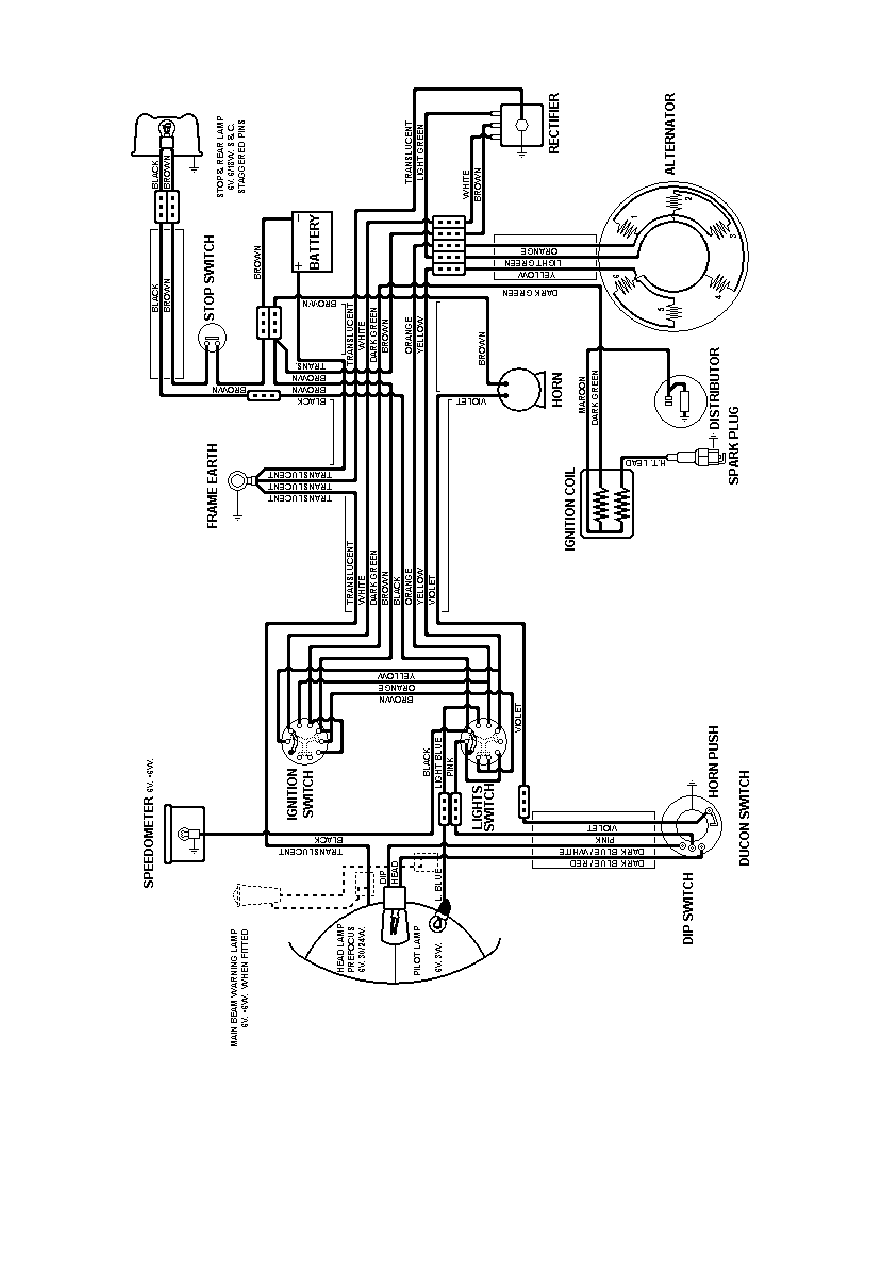
Fig. 10. Wiring Diagram (Supreme and Sports models)
34
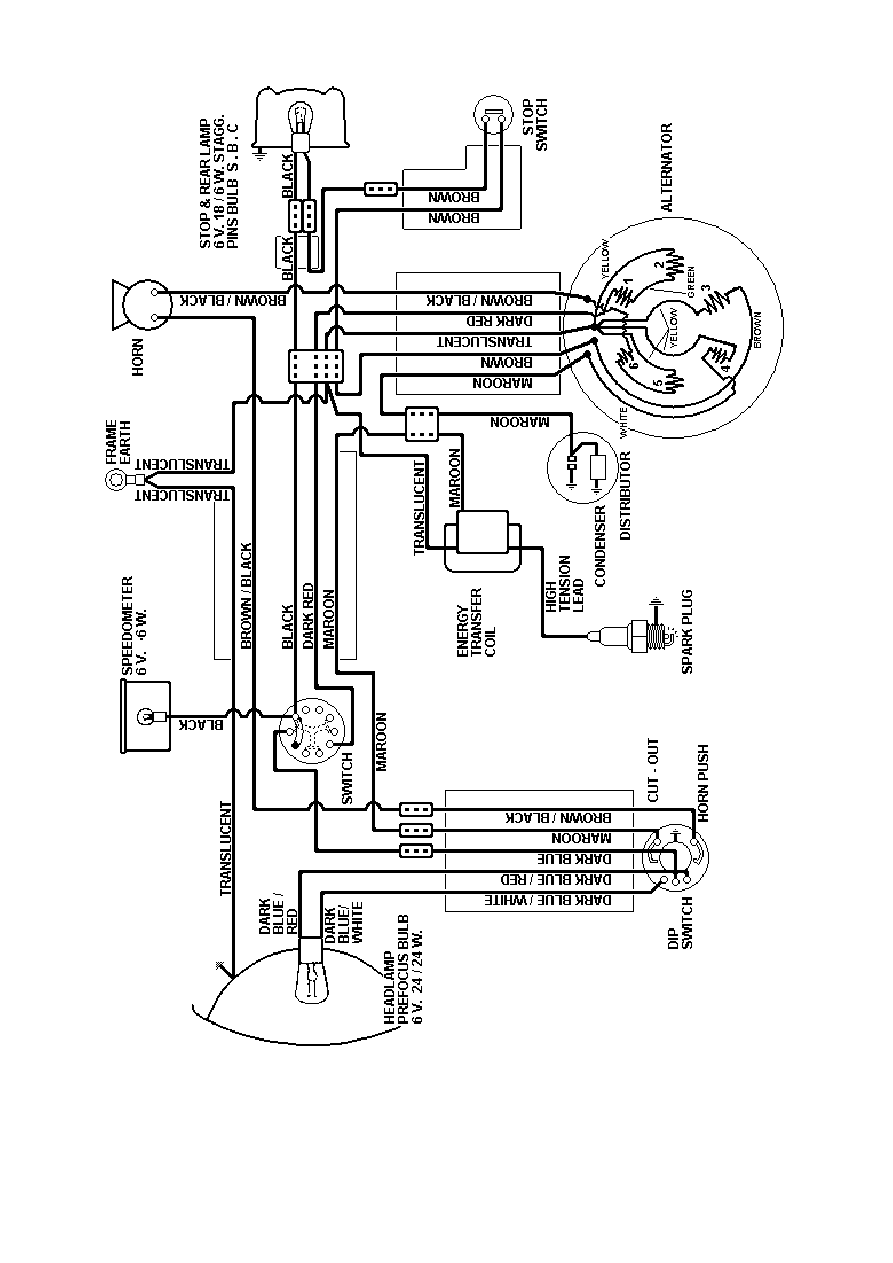
Fig. 11. Wiring Diagram (Bushman model)
35
Wyszukiwarka
Podobne podstrony:
BSA Workshop Manual D14 4
DJ F1 S1 Instruction Manual
Instruction Manual
ICOM instruction manual[1]
DJ F1 S1 Instruction Manual
09 INSTRUCTION MANUAL OIL PUMP 12143 3055 E
MALOWANIE LINJI easylineedge instruction manual
Instrukcja (manual) wymiany linek hamulca ręcznego (pomocniczego, awaryjnego) fiat punto I (1,1)
102003BGA Reballing Instruction Manual
#0449 – Using an Instruction Manual
06 INSTRUCTION MANUAL FUEL OIL FILTER 12153 3188 E
07c John Ashbery The Instruction Manual
08 INSTRUCTION MANUAL TEMPERATURE CONTROL VALVE 12160 3078
DocLib 5086 FP 120, FP 130, FP 160 MIG Welding System Instruction Manual (0056 1842)
05 INSTRUCTION MANUAL COUPLING M8090901A
więcej podobnych podstron