FP-120, FP-130 and FP-160
MIG Welding System
Instruction Manual
FORM NO. 0056-1842
EFFECTIVE July 2001
Safety and Operating
Instructions
For Your Safety . . .
PLEASE READ
CAREFULLY!

Table of Contents
page
Introduction . . . . . . . . . . . . . . . . . . . . . . . . . . . . . . . . . . . . . . . . . . . . . . . . . . . . . . . . . . . . . . . . . . . . . . . . . . .1
Safety Profile . . . . . . . . . . . . . . . . . . . . . . . . . . . . . . . . . . . . . . . . . . . . . . . . . . . . . . . . . . . . . . . . . . . . . . . . . .1
Safety Information . . . . . . . . . . . . . . . . . . . . . . . . . . . . . . . . . . . . . . . . . . . . . . . . . . . . . . . . . . . . . . . . . . . . . .1
Safety Symbols . . . . . . . . . . . . . . . . . . . . . . . . . . . . . . . . . . . . . . . . . . . . . . . . . . . . . . . . . . . . . . . . . . . . . . . .1
General Welding Safety Instructions . . . . . . . . . . . . . . . . . . . . . . . . . . . . . . . . . . . . . . . . . . . . . . . . . . . . . . . .3
Location . . . . . . . . . . . . . . . . . . . . . . . . . . . . . . . . . . . . . . . . . . . . . . . . . . . . . . . . . . . . . . . . . . . . . . . . . . .3
Personal Protection . . . . . . . . . . . . . . . . . . . . . . . . . . . . . . . . . . . . . . . . . . . . . . . . . . . . . . . . . . . . . . . . . .3
Safety Instructions . . . . . . . . . . . . . . . . . . . . . . . . . . . . . . . . . . . . . . . . . . . . . . . . . . . . . . . . . . . . . . . . . . .3
Fire Prevention . . . . . . . . . . . . . . . . . . . . . . . . . . . . . . . . . . . . . . . . . . . . . . . . . . . . . . . . . . . . . . . . . . . . . .3
Ventilation . . . . . . . . . . . . . . . . . . . . . . . . . . . . . . . . . . . . . . . . . . . . . . . . . . . . . . . . . . . . . . . . . . . . . . . . .4
Electromagnetic Compatibility . . . . . . . . . . . . . . . . . . . . . . . . . . . . . . . . . . . . . . . . . . . . . . . . . . . . . . . . . .4
Protective Welding Gasses . . . . . . . . . . . . . . . . . . . . . . . . . . . . . . . . . . . . . . . . . . . . . . . . . . . . . . . . . . . . .4
Health Hazards . . . . . . . . . . . . . . . . . . . . . . . . . . . . . . . . . . . . . . . . . . . . . . . . . . . . . . . . . . . . . . . . . . . . . .5
Electric Shock . . . . . . . . . . . . . . . . . . . . . . . . . . . . . . . . . . . . . . . . . . . . . . . . . . . . . . . . . . . . . . . . . . . . . .5
Welder Specifications . . . . . . . . . . . . . . . . . . . . . . . . . . . . . . . . . . . . . . . . . . . . . . . . . . . . . . . . . . . . . . . . . . . .5
Welder Operating Characteristics . . . . . . . . . . . . . . . . . . . . . . . . . . . . . . . . . . . . . . . . . . . . . . . . . . . . . . . . . . .6
Internal Thermal Overload Protection . . . . . . . . . . . . . . . . . . . . . . . . . . . . . . . . . . . . . . . . . . . . . . . . . . . . . . .6
Specifications for FP 120 Wire (GMAW/FCAW) Welding System (1444-0304) . . . . . . . . . . . . . . . . . . . . .6
Specifications for FP 130 Wire (GMAW/FCAW) Welding System (1444-0306) . . . . . . . . . . . . . . . . . . . . .7
Specifications for FP 160 Wire (GMAW/FCAW) Welding System (1444-0308) . . . . . . . . . . . . . . . . . . . . .7
MIG Gun Specifications . . . . . . . . . . . . . . . . . . . . . . . . . . . . . . . . . . . . . . . . . . . . . . . . . . . . . . . . . . . . . . .7
Duty Cycle . . . . . . . . . . . . . . . . . . . . . . . . . . . . . . . . . . . . . . . . . . . . . . . . . . . . . . . . . . . . . . . . . . . . . .8
Welder Installation . . . . . . . . . . . . . . . . . . . . . . . . . . . . . . . . . . . . . . . . . . . . . . . . . . . . . . . . . . . . . . . . . . . . . .8
Power Source Connection . . . . . . . . . . . . . . . . . . . . . . . . . . . . . . . . . . . . . . . . . . . . . . . . . . . . . . . . . . . . .8
Power Requirements . . . . . . . . . . . . . . . . . . . . . . . . . . . . . . . . . . . . . . . . . . . . . . . . . . . . . . . . . . . . . . .8
Connection to Power Source . . . . . . . . . . . . . . . . . . . . . . . . . . . . . . . . . . . . . . . . . . . . . . . . . . . . . . . . .8
Extension Cords . . . . . . . . . . . . . . . . . . . . . . . . . . . . . . . . . . . . . . . . . . . . . . . . . . . . . . . . . . . . . . . . . .9
Machine Assembly . . . . . . . . . . . . . . . . . . . . . . . . . . . . . . . . . . . . . . . . . . . . . . . . . . . . . . . . . . . . . . . . . . .9
MIG Gun Installation . . . . . . . . . . . . . . . . . . . . . . . . . . . . . . . . . . . . . . . . . . . . . . . . . . . . . . . . . . . . . . . . .9
Installation of the Welding Wire . . . . . . . . . . . . . . . . . . . . . . . . . . . . . . . . . . . . . . . . . . . . . . . . . . . . . . . . . . .10
Gas Cylinder and Regulator Connection . . . . . . . . . . . . . . . . . . . . . . . . . . . . . . . . . . . . . . . . . . . . . . . . . . . . .11
MIG Gun . . . . . . . . . . . . . . . . . . . . . . . . . . . . . . . . . . . . . . . . . . . . . . . . . . . . . . . . . . . . . . . . . . . . . . . . . . . .11
MIG Welding . . . . . . . . . . . . . . . . . . . . . . . . . . . . . . . . . . . . . . . . . . . . . . . . . . . . . . . . . . . . . . . . . . . . . . . . .11
Gasless Welding . . . . . . . . . . . . . . . . . . . . . . . . . . . . . . . . . . . . . . . . . . . . . . . . . . . . . . . . . . . . . . . . . . . . . . .12
Advantages of Gasless Welding . . . . . . . . . . . . . . . . . . . . . . . . . . . . . . . . . . . . . . . . . . . . . . . . . . . . . . . .12
Preparation for Welding . . . . . . . . . . . . . . . . . . . . . . . . . . . . . . . . . . . . . . . . . . . . . . . . . . . . . . . . . . . . . . . . .12
Welding Procedures . . . . . . . . . . . . . . . . . . . . . . . . . . . . . . . . . . . . . . . . . . . . . . . . . . . . . . . . . . . . . . . . . . . .13
Replacement of the Wire Spool . . . . . . . . . . . . . . . . . . . . . . . . . . . . . . . . . . . . . . . . . . . . . . . . . . . . . . . . . . .14
Welding Tips . . . . . . . . . . . . . . . . . . . . . . . . . . . . . . . . . . . . . . . . . . . . . . . . . . . . . . . . . . . . . . . . . . . . . . . . .14
Spot Welding . . . . . . . . . . . . . . . . . . . . . . . . . . . . . . . . . . . . . . . . . . . . . . . . . . . . . . . . . . . . . . . . . . . . . . . . .14
Adjustment of the Power Source . . . . . . . . . . . . . . . . . . . . . . . . . . . . . . . . . . . . . . . . . . . . . . . . . . . . . . . . . .14
Additional Safety Information . . . . . . . . . . . . . . . . . . . . . . . . . . . . . . . . . . . . . . . . . . . . . . . . . . . . . . . . . . . .15
Troubleshooting Information . . . . . . . . . . . . . . . . . . . . . . . . . . . . . . . . . . . . . . . . . . . . . . . . . . . . . . . . . . . . .16
General Operating Tips . . . . . . . . . . . . . . . . . . . . . . . . . . . . . . . . . . . . . . . . . . . . . . . . . . . . . . . . . . . . . .17
Troubleshooting Guide for Firepower FP-200 MIG Gun . . . . . . . . . . . . . . . . . . . . . . . . . . . . . . . . . . . . . . . .17
FP-200 Wire Liner Replacement . . . . . . . . . . . . . . . . . . . . . . . . . . . . . . . . . . . . . . . . . . . . . . . . . . . . . . . . . .18

page
FP-120 Parts List . . . . . . . . . . . . . . . . . . . . . . . . . . . . . . . . . . . . . . . . . . . . . . . . . . . . . . . . . . . . . . . . . . . . . .20
FP-130 Parts List . . . . . . . . . . . . . . . . . . . . . . . . . . . . . . . . . . . . . . . . . . . . . . . . . . . . . . . . . . . . . . . . . . . . . .22
FP-160 Parts List . . . . . . . . . . . . . . . . . . . . . . . . . . . . . . . . . . . . . . . . . . . . . . . . . . . . . . . . . . . . . . . . . . . . . .24
Firepower Limited Warranty . . . . . . . . . . . . . . . . . . . . . . . . . . . . . . . . . . . . . . . . . . . . . . . . . . . . . . . . . . . . .28
Table of Illustrations
page
Figure 1: Feet and Handle Installation . . . . . . . . . . . . . . . . . . . . . . . . . . . . . . . . . . . . . . . . . . . . . . . . . . . . . . .9
Figure 2: MIG Gun Installation . . . . . . . . . . . . . . . . . . . . . . . . . . . . . . . . . . . . . . . . . . . . . . . . . . . . . . . . . . . .9
Figure 3: Wire Installation . . . . . . . . . . . . . . . . . . . . . . . . . . . . . . . . . . . . . . . . . . . . . . . . . . . . . . . . . . . . . . .10
Figure 4: Gas Cylinder Connection . . . . . . . . . . . . . . . . . . . . . . . . . . . . . . . . . . . . . . . . . . . . . . . . . . . . . . . .11
Figure 5: Polarity Preparation . . . . . . . . . . . . . . . . . . . . . . . . . . . . . . . . . . . . . . . . . . . . . . . . . . . . . . . . . . . .13
Figure 6: Power Source . . . . . . . . . . . . . . . . . . . . . . . . . . . . . . . . . . . . . . . . . . . . . . . . . . . . . . . . . . . . . . . . .14
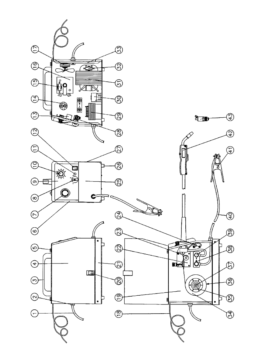
Figure 8: FP 120 Parts Breakdown . . . . . . . . . . . . . . . . . . . . . . . . . . . . . . . . . . . . . . . . . . . . . . . . . . . . . . . . .19
Figure 9: FP 130 Parts Breakdown . . . . . . . . . . . . . . . . . . . . . . . . . . . . . . . . . . . . . . . . . . . . . . . . . . . . . . . . .21
Figure 10: FP 160 Parts Breakdown . . . . . . . . . . . . . . . . . . . . . . . . . . . . . . . . . . . . . . . . . . . . . . . . . . . . . . . .23
Figure 11: FP 120 Wiring Diagram . . . . . . . . . . . . . . . . . . . . . . . . . . . . . . . . . . . . . . . . . . . . . . . . . . . . . . . .25
Figure 12: FP 130 Wiring Diagram . . . . . . . . . . . . . . . . . . . . . . . . . . . . . . . . . . . . . . . . . . . . . . . . . . . . . . . .26
Figure 13: FP 160 Wiring Diagram . . . . . . . . . . . . . . . . . . . . . . . . . . . . . . . . . . . . . . . . . . . . . . . . . . . . . . . .27

INTRODUCTION
This User’s Guide provides specific information about your Firepower Welding System. This guide provides
pertinent information needed to safely and effectively use your Firepower Welding System. The information in
this manual applies to specific Firepower Welding System models. It gives instructions on set-up, installation
and actual use of your Firepower Welding System.
SAFETY PROFILE
Tradesmen respect the tools and equipment with which they work. They are also aware that tools and equip-
ment are dangerous if used improperly or abused.
Read this guide prior to using your welding system. It enables you to do a better and safer job. You will also
learn the machine’s application, limitations and the specific potential hazards related to welding.
SAFETY INFORMATION
The following safety information is provided to you as a guideline. Use it to operate your new Firepower
Welding System under the safest possible conditions. Any equipment that uses electrical power is potentially
dangerous to use when the safety or safe handling instructions are not known and/or are not followed. This
safety information gives you the necessary information for safe use and operation.
Items in this manual that significantly affect safety are identified with the following headings. Please read and
understand this manual. Pay special attention to items identified with these headings.
- Means there is a possibility of injury or death to yourself or others if the proper
safety precautions are not followed.
- Means there is the possibility of damage to the Firepower Welding System or
other property.
- Indicates points of interest for more efficient and convenient installation or opera-
tion. It may be used before or after a procedure to highlight or better explain the step.
READ ALL SAFETY AND WARNING INSTRUCTIONS CAREFULLY before attempting to install, oper-
ate or service this welding unit. Your failure to comply with the instructions could result in personal injury
and/or property damage.
RETAIN THESE INSTRUCTIONS FOR YOUR FUTURE REFERENCE.
SAFETY SYMBOLS
Familiarize yourself with the warning symbols listed on the following pages. These symbols identify important
safety messages in this manual. When you see one of these symbols, be alert to the possibility of personal
injury and carefully read the message that follows.
Indicates that the possibility of electric shock hazard exists during the operation of the step(s) that
follow.
Indicates that the possibility of fire hazard exists during the operation of the step(s) that follow.

Indicates that the helmet must be worn during the step(s) that follow to protect against eye damage
and burns due to flash hazard.
Indicates that the possibility of toxic gas hazard exists during operation of the step(s) that follow.
Indicates that the possibility of being burned by hot slag exists during operation of the step(s) that
follow.
Indicates that eye protection should be worn to protect against flying debris in the following step(s).
Indicates that the possibility of injury or death exist due to improper handling and maintenance of
compressed gas cylinders or regulators.
ELECTRIC SHOCK CAN KILL! Reduce the risk of death or serious injury from shock. Read,
understand and follow the following safety instructions. Additionally, make certain that anyone else
who uses this welding equipment, or who is a bystander in the welding area, understands and fol-
lows these safety instructions as well.
FIRE OR EXPLOSION CAN CAUSE DEATH, INJURY AND PROPERTY DAMAGE! Reduce
the risk of death, injury or property damage from fire or explosion. Read, understand and follow the
following safety instructions. Additionally, make certain that anyone else who uses this welding
equipment, or who is a bystander in the welding area, understands and follows these safety instruc-
tions as well. Remember, welding by nature produces sparks, hot spatter, molten metal drops, hot
slag and hot metal parts that can start fires, burn skin and damage eyes.
ARC RAYS CAN INJURE EYES AND BURN SKIN! Reduce the risk of injury from arc rays.
Read, understand and follow the following safety instructions. Additionally, make certain that any-
one else who uses this welding equipment, or who is a bystander in the welding area, understands
and follows these safety instructions as well.
FUMES, GASSES AND VAPORS CAN CAUSE DISCOMFORT, ILLNESS AND DEATH!
Reduce the risk of discomfort, illness or death. Read, understand and follow the following safety
instructions. Additionally, make certain that anyone else who uses this welding equipment, or who
is a bystander in the welding area, understands and follows these safety instructions as well.
2

IMPROPER HANDLING AND MAINTENANCE OF COMPRESSED GAS CYLINDERS AND
REGULATORS CAN RESULT IN SERIOUS INJURY OR DEATH! Reduce the risk of injury or
death from compressed gasses and equipment hazards. Read, understand and follow the following
safety instructions. Additionally, make certain that anyone else who uses this welding equipment, or
who is a bystander in the welding area, understands and follows these safety instructions as well.
GENERAL WELDING SAFETY INSTRUCTIONS
LOCATION
Welding processes of any kind can be dangerous not only to the operator but to
any person situated near the equipment, if safety and operating rules are not strictly
observed.
PERSONAL PROTECTION
1.
Wear closed, non-flammable protective clothing, without pockets or turned up trousers.
2. Wear a non-flammable welding helmet to shield the neck, face and sides of the head. Keep the protective
lens clean. Replace the protective lens if broken or cracked. Position a transparent glass between the lens and
the welding area. Weld in a closed, well ventilated area that does not open into other working areas.
3. NEVER look at the arc without proper protection to the eyes.
4. Thoroughly clean metal of rust or paint to avoid producing harmful fumes. Parts degreased with a solvent
must dry before welding.
5. NEVER weld on metals or coated metals containing zinc, mercury, chromium, graphite, lead, cadmium or
beryllium unless the operator and the people standing in the same area use an air-supplied respirator.
SAFETY INSTRUCTIONS
For your safety, BEFORE connecting the power source to the line, follow these instructions:
1. Insert an adequate two-pole switch, equipped with time-delay fuses, before the main outlet.
2. Make the single-phase connection with a two-pole plug compatible with the above mentioned socket.
3. The two wires of the two-pole input cable are used for the connection with the single-phase line. The yel-
low/green wire is for the compulsory connection to the ground in the welding area.
4. When working in a confined space, keep the power source outside the welding area and fix the ground cable
to the workpiece. NEVER work in a damp or wet area.
5. DONOT use damaged input or welding cables.
6.
NEVER operate the power source without its panels in place. This could cause serious injury
to the operator and could damage the equipment.
FIRE PREVENTION
Welding operations use fire or combustion as a basic tool.
1. The work area MUST have a fireproof floor.
2. Work benches or tables used during welding operations MUST have fireproof tops. DONOT weld on
wooden work benches.
3. Use heat-resistant shields or other approved material to protect nearby walls or unprotected flooring from
sparks and hot metal.
4. Keep an approved fire extinguisher of the proper size and type in the work area. Inspect it regularly to
ensure that it is in proper working order. Know how to use the fire extinguisher.
3

5. Remove all combustible materials from the work site. If you can not remove them, protect them with fire-
proof covers.
NEVER perform welding operations on a container that has held toxic, com-
bustible or flammable liquids or vapors. NEVER perform welding operations in an area con-
taining combustible vapors, flammable liquids or explosive dust.
VENTILATION
Ventilate welding work areas adequately. Maintain sufficient air flow to prevent
accumulation of explosive or toxic concentrations of gases. Welding operations using cer-
tain combinations of metals, coatings and gases generate toxic fumes. Use respiratory
protection equipment in these circumstances. BEFORE welding, read and understand the
Material Safety Data Sheet for the welding alloy.
ELECTROMAGNETIC COMPATIBILITY
BEFORE installing a MIG power source, inspect the surrounding area checking the following points:
1. Make sure there are no other power supply cables, control lines, telephone cables or other devices close to
the power source.
2. Make sure that telephones, televisions, computers or other control systems are not in the working area.
3. People with pace-makers or hearing aides should keep far from the power source. In particular cases, special
protection measures may be required.
Reduce interference by following these suggestions:
1. If there is interference in the power source line, mount an E.M.T. filter between the power supply and the
power source.
2. Shorten the output cables of the power source, keep them together and connected to ground.
3. Securely fasten the panels of the power source in place after performing maintenance.
PROTECTIVE WELDING GASSES
1. These welders use only inert or non-flammable gases for welding arc protection. It is important to choose
the appropriate gas for the type of welding being performed.
2. DONOT use gas from unidentified cylinders.
3. DONOT connect the cylinder directly to the welder. ALWAYS use a pressure regulator.
4. Make sure the pressure regulator functions properly. Read the instructions supplied with the regulator.
5. DONOT lubricate the regulator with oil or grease.
6. Each regulator is designed for use with a specific gas. Make sure the regulator is designed for the protective
gas being used.
7. DONOT use damaged cylinders.
8. Make sure that the cylinder is safely secured tightly to the welder with the chain provided.
9. DONOT carry the cylinder by holding it by the valve.
10. NEVER expose cylinders to excessive heat, sparks, slag or flame.
11. Make sure that the gas hose is ALWAYS in good condition.
12. Keep the gas hose away from the working area.
4
HEALTH HAZARDS
The welding process can be hazardous to your health. Therefore, follow these precautions:
1. ALWAYS wear protective clothing without pockets and cuffs. Wear a helmet, gloves and shoes with an insu-
lating sole.
2. ALWAYS use a welding mask or helmet with the properly tinted protective glass in the shade adequate to
the welding operation being performed and to the current intensity.
3. Make certain that bystanders in the welding area are also following these precautions.
4. ALWAYS keep the welding mask glass clean. Replace it if it is cracked or chipped.
5. NEVER weld in a damp area or come in contact with a moist or wet surface when welding.
6. If the welding area lacks proper ventilation, use fume extractors.
7. Clean the welding pieces from solvents or alogenous grease which develop toxic gases when exposed to
heat.
ELECTRIC SHOCK
ELECTRIC SHOCK CAN KILL! Reduce the risk of death or serious
injury from shock. Read, understand and follow ALL safety instructions. Be sure that
everyone who uses this welding equipment or who is a bystander in the welding area
understands and follows ALL safety instructions as well.
ELECTRIC SHOCK CAN BE FATAL. A person qualified in First Aid
techniques should ALWAYS be present in the working area. If a person is uncon-
scious and electric shock is suspected, DO NOT touch the person if he or she is in
contact with cables. Disconnect power from the machine, then use First Aid. Use
dry wood or other insulating materials to move cables, if necessary, away from the
person.
1. Never touch or come in physical contact with any part of the input current circuit and welding current cir-
cuit.
2. Frequently, check that the input cable and plug are in good condition.
3. Make sure that the welder is disconnected from the mains BEFORE attempting any repairs, opening the side
panels of the machine or repairing the input cable.
4. Fit the main line, BEFORE the distribution outlet, with a three-poles switch with adequate delayed fuses
(check the characteristics plate for fuse values).
5. DONOT weld with cables, torch or earth clamp in poor shape.
6. DONOT coil the torch or the earth cables around your body.
7. DONOT aim the welding torch against yourself or against bystanders.
8. Should you feel the slightest electrical shock, STOP welding IMMEDIATELY. DONOT use the welder
until the fault is found and resolved.
WELDER SPECIFICATIONS
Your new Firepower Wire MIG (GMAW) and Flux Core (FCAW) Wire Welding System is designed for main-
tenance and sheet metal fabrication. The unit consists of a single-phase power transformer power source, arc
stabilizer, rectifier and heavy-duty wire feed system. This welding power source is capable of welding with
0.023 inch (0.6 mm) or 0.030 inch (0.8 mm) solid steel MIG (GMAW) welding wire. A shielding gas is neces-
sary for this process.
5

This unit is also capable of welding with either 0.030 inch (0.8 mm) or 0.035 inch (0.9 mm) flux cored weld-
ing wire (FCAW) process. The use of shielding gas is not required for this welding process. Please refer to the
instructions provided in this manual for proper machine setup.
The use of larger diameter wire makes welding difficult. The results cannot be guaranteed. The manufacturer
DOES NOT recommend using larger diameter welding wire with this unit.
WELDER OPERATING CHARACTERISTICS
The duty rating defines how long the welding system can be used before it must pause and cool down. Duty Cycle
ratings are expressed as a percentage of a ten-minute period. It represents the maximum welding time allowed at
the specified amperage setting. The remaining balance of a ten-minute period is required for cooling off the unit.
Firepower 120 volt Welding Systems have duty cycle ratings based on 15 amp and 20 amp input currents.
Please refer to the data plate located on the front of the unit for the specific rating that applies to your unit.
All Firepower 230 volt Welding Systems are rated at the required input amperage for proper operation. Please
refer to the data plate located on the front of the unit for the specific rating that applies to your unit.
INTERNAL THERMAL OVERLOAD PROTECTION
DO NOT exceed the duty cycle or damage could result to your welder. If you do
exceed the duty cycle of your welder, the internal thermal overload protection shuts off all
welder functions except the cooling fan. If this happens, DO NOT SHUT OFF THE WELDER.
Leave the welder turned on and the fan running. After the welder is properly cooled, the ther-
mal protector automatically resets and your welder will function properly.
If you find that your welder does not weld for a 2-minute time period without stopping, reduce the wire speed
slightly. Welding with the wire speed set too high not only causes poor visible welds but also increases amper-
age draw and shortens the duty cycle.
SPECIFICATIONS FOR FP 120 WIRE(GMAW/FCAW) WELDING SYSTEM (1444-0304)
Type . . . . . . . . . . . . . . . . . . . . . . . . . . . . . . . . . . . . . . . . . . . . . . . . . . . . . . . . .110 AMP MIG Welding System
Input Voltage . . . . . . . . . . . . . . . . . . . . . . . . . . . . . . . . . . . . . . . . . . . . . . . . . . . . . . . . . . . . . .120 Volt (60 Hz)
Rated Output . . . . . . . . . . . . . . . . . . . . . . . . . . . . . . . . . . . . . . . . . . . . . . . . . . . .88 Amps @ 20% Duty Cycle
Agency Approval . . . . . . . . . . . . . . . . . . . . . . . . . . . . . . . . . . . . . . .CSA Rating 60 Amps @ 20% Duty Cycle
Maximum Output . . . . . . . . . . . . . . . . . . . . . . . . . . . . . . . . . . . . . . . . . . . . . . . . . . . . . . . . . . .110 Amps Peak
Output Power Settings . . . . . . . . . . . . . . . . . . . . . . . . . . . . . . . . . . . . . . . . . . . . .Four Position (Rotary Switch)
Wire Speed Adjustment . . . . . . . . . . . . . . . . . . . . . . . . . . . . . . . . . .Infinite Speed Controlled by Potentiometer
Overload Indicator . . . . . . . . . . . . . . . . . . . . . . . . . . . . . . . . . . . . . . . . . . . . . . . . . . . . .Illuminated Pilot Light
Power Switch . . . . . . . . . . . . . . . . . . . . . . . . . . . . . . . . . . . . . . . . . . . . . . . . . . . . .Illuminated ON/OFF Switch
Power Cord . . . . . . . . . . . . . . . . . . . . . . . . . . . . . . . . . . . . . . . . . . . . .6 foot 15 Amp NEMA 5-15 Power Plug
MIG Gun . . . . . . . . . . . . . . . . . .10 foot FIREPOWER® with ON/OFF Contactor Control-Gas Valve in Handle
Ground Cable and Clamp . . . . . . . . . . . . . . . . . . . . . . . . . . . . . .6 foot Ground Cable/200 Amp Ground Clamp
MIG Gun Connection . . . . . . . . . . . . . . . . . . . . . . . . . . . . . . . . . . . . . . . . . . . . . . . . . . . . . . .Fixed Connection
Spool Capacity . . . . . . . . . . . . . . . . . . . . . . . . . . . . . . . . . . . . . . . . . . . . . . . . . . . . . . . . . . . . . . .2 lb and 10 lb
Accessories . . . . . . . . . . . . . . . . . . . . . . . . . . . . . . . . . . . . . . . . . . . . . . . . . . . . . . . . . . . . . . . . . . .Contact Tip
MIG Nozzle
1 lb. .030 MIG Wire
FIREPOWER® Argon Regulator
FIREPOWER® MIG Gun
Instruction Manual
6

SPECIFICATIONS FOR FP 130 WIRE(GMAW/FCAW) WELDING SYSTEM (1444-0306)
Type . . . . . . . . . . . . . . . . . . . . . . . . . . . . . . . . . . . . . . . . . . . . . . . . . . . . . . . . .120 AMP MIG Welding System
Input Voltage . . . . . . . . . . . . . . . . . . . . . . . . . . . . . . . . . . . . . . . . . . . . . . . . . . . . . . . . . . . . . .120 Volt (60 Hz)
Rated Output . . . . . . . . . . . . . . . . . . . . . . . . . . . . . . . . . . . . . . . . . . . . . . . . . . . .88 Amps @ 40% Duty Cycle
Agency Approval . . . . . . . . . . . . . . . . . . . . . . . . . . . . . . . . . . . . . . .CSA Rating 60 Amps @ 60% Duty Cycle
Maximum Output . . . . . . . . . . . . . . . . . . . . . . . . . . . . . . . . . . . . . . . . . . . . . . . . . . . . . . . . . . .120 Amps Peak
Output Power Settings . . . . . . . . . . . . . . . . . . . . . . . . . . . . . . . . . . . . . . . . . . . . .Four Position (Rotary Switch)
Wire Speed Adjustment . . . . . . . . . . . . . . . . . . . . . . . . . . . . . . . . . .Infinite Speed Controlled by Potentiometer
Overload Indicator . . . . . . . . . . . . . . . . . . . . . . . . . . . . . . . . . . . . . . . . . . . . . . . . . . . . .Illuminated Pilot Light
Power Switch . . . . . . . . . . . . . . . . . . . . . . . . . . . . . . . . . . . . . . . .Illuminated ON/OFF Switch UL/CSA Listed
Power Cord . . . . . . . . . . . . . . . . . . . . . . . . . . . . . . . . . . . . . . . . . . . . .6 foot 15 Amp NEMA 5-15 Power Plug
MIG Gun . . . . . . . . . . . . . . . . . .10 foot FIREPOWER® with ON/OFF Contactor Control-Gas Valve in Handle
Ground Cable and Clamp . . . . . . . . . . . . . . . . . . . . . . . . . . . . . .6 foot Ground Cable 200 Amp Ground Clamp
MIG Gun Connection . . . . . . . . . . . . . . . . . . . . . . . . . . . . . . . . . . . . . . . . . . . . . . . . . . . . . . .Fixed Connection
Spool Capacity . . . . . . . . . . . . . . . . . . . . . . . . . . . . . . . . . . . . . . . . . . . . . . . . . . . . . . . . . . . . . . .2 lb and 10 lb
Accessories . . . . . . . . . . . . . . . . . . . . . . . . . . . . . . . . . . . . . . . . . . . . . . . . . . . . . . . . . . . . . . . . . . .Contact Tip
MIG Nozzle
1 lb. .030 MIG Wire
FIREPOWER® Argon Regulator
FIREPOWER® MIG Gun
Instruction Manual
SPECIFICATIONS FOR FP 160 WIRE(GMAW/FCAW) WELDING SYSTEM (1444-0308)
Type . . . . . . . . . . . . . . . . . . . . . . . . . . . . . . . . . . . . . . . . . . . . . . . . . . . . . . . . .155 AMP MIG Welding System
Input Voltage . . . . . . . . . . . . . . . . . . . . . . . . . . . . . . . . . . . . . . . . . . . . . . . . . . . . . . . . . . . . . .230 Volt (60 Hz)
Rated Output . . . . . . . . . . . . . . . . . . . . . . . . . . . . . . . . . . . . . . . . . . . . . . . . . . . .130 Amps @ 20% Duty Cycle
Agency Approval . . . . . . . . . . . . . . . . . . . . . . . . . . . . . . . . . . . . . . .CSA Rating 120 Amps @ 25% Duty Cycle
Maximum Output . . . . . . . . . . . . . . . . . . . . . . . . . . . . . . . . . . . . . . . . . . . . . . . . . . . . . . . . . . .155 Amps Peak
Output Power Settings . . . . . . . . . . . . . . . . . . . . . . . . . . . . . . . . . . . . . . . . . . .FOUR Position (Rotary Switch)
Wire Speed Adjustment . . . . . . . . . . . . . . . . . . . . . . . . . . . . . . . . . .Infinite Speed Controlled by Potentiometer
Overload Indicator . . . . . . . . . . . . . . . . . . . . . . . . . . . . . . . . . . . . . . . . . . . . . . . . . . . . .Illuminated Pilot Light
Power Switch . . . . . . . . . . . . . . . . . . . . . . . . . . . . . . . . . . . . . . . .Illuminated ON/OFF Switch UL/CSA Listed
Power Cord without plug . . . . . . . . . . . . . . . . . . . . . . . . . . . . . . . . . . . . . . . . . . . . . . . . . . . . . . . . . . . . .6 foot
MIG Gun . . . . . . . . . . . . . . . . . .10 foot FIREPOWER® with ON/OFF Contactor Control-Gas Valve in Handle
Ground Cable and Clamp . . . . . . . . . . . . . . . . . . . . . . . . . . . . . .6 foot Ground Cable 200 Amp Ground Clamp
MIG Gun Connection . . . . . . . . . . . . . . . . . . . . . . . . . . . . . . . . . . . . . . . . . . . . . . . . . . . . . . .Fixed Connection
Spool Capacity . . . . . . . . . . . . . . . . . . . . . . . . . . . . . . . . . . . . . . . . . . . . . . . . . . . . . . . . . . . . . . .2 lb and 10 lb
Accessories . . . . . . . . . . . . . . . . . . . . . . . . . . . . . . . . . . . . . . . . . . . . . . . . . . . . . . . . . . . . . . . . . . .Contact Tip
MIG Nozzle
1 lb. .030 MIG Wire
FIREPOWER® Argon Regulator
FIREPOWER® MIG Gun
Instruction Manual
MIG-GUN SPECIFICATIONS
Process . . . . . . . . . . . . . . . . . . . . . . . . . . . . . . . . . . . . . . . . . . . . . . . . . . . . . . . . . . .(GMAW/FCAW) Welding
Type of Cooling . . . . . . . . . . . . . . . . . . . . . . . . . . . . . . . . . . . . . . . . . . . . . . . . . . . . . . . . . .Air or Cooling Gas
7

Duty Cycle
MIG-GUN
10% DUTY
35% DUTY
60% DUTY
100% DUTY
MODEL NO.
CYCLE
CYCLE
CYCLE
CYCLE
150
230 amps
205 amps
180 amps
140 amps
200
320 amps
290 amps
250 amps
195 amps
300
500 amps
450 amps
400 amps
275 amps
WELDER INSTALLATION
POWER SOURCE CONNECTION
Power Requirements
This welder is designed to operate on a properly grounded 120 volt, 60 HZ, single-phase alternating current
(AC) power source fused with a 20 amp time-delayed fuse or circuit breaker. (FP 160 requires 230 Volt, 60 HZ,
single phase AC. Please consult local codes for proper plug and receptacle applications.) A qualified electrician
should verify the ACTUAL VOLTAGE at the receptacle into which the welder will be plugged and confirm
that the receptacle is properly grounded. The use of the proper circuit size can eliminate the nuisance of circuit
breaker tripping when welding.
DO NOT OPERATE THE FP-120 OR FP-130 WELDER if the ACTUAL power source voltage is less than
110 Volts AC or greater than 132 Volts AC. Contact a qualified electrician if this problem exists. Improper per-
formance and/or damage to the welder will result if operated on inadequate or excessive power.
DO NOT OPERATE THE FP-160 WELDER if the ACTUAL power source voltage is less than 208 Volts
AC or greater than 245 Volts AC. Contact a qualified electrician if this problem exists. Improper performance
and/or damage to the welder will result if operated on inadequate or excessive power.
Connection to Power Source
High voltage danger from power source! Consult a qualified electrician for
proper installation of receptacle at the power source.
This welder must be grounded while in use to protect the operator from electrical shock. If you are not sure if your
outlet is properly grounded, have it checked by a qualified electrician. DONOT cut off the grounding prong or alter
the plug in any way. DONOT use any adapters between the welder’s power cord and the power source receptacle.
Make sure the POWER switch is OFF. Connect the welder’s power cord to a prop-
erly grounded 120 VAC, 60 Hz, single-phase, 20 amp power source. DO NOT operate this
welder if the source voltage is less than 110 Volts AC or greater than 132 Volts AC. Contact a
qualified electrician if this problem exists. Improper performance and/or damage to the welder
will result if operated on inadequate or excessive power.
Extension Cords
For optimum welder performance, an extension cord should not be used unless absolutely necessary. If neces-
sary, care must be taken in selecting an extension cord appropriate for use with your specific welder.
Select a properly grounded extension cord that will mate directly with the ac power source receptacle and the
welder power cord without the use of adapters. Make certain that the extension cord is properly wired and in
good electrical condition (minimum gauge size 10/3 AWG).
MACHINE ASSEMBLY
1. Unpack the welder.
2. Lay the power source on one side and fix the four rubber feet (front and back) to the base of the machine
using the four screws supplied in the kit. Bring the power source back to the upright position.
8
3. Assemble the plastic handle as shown in Figure 1.
4. Tools required: Allen Wrench.
Be sure that the welder’s electri-
cal power supply cord is not connected while
performing this procedure.
5. Install MIG gun per instructions.
6. Install welding wire per instructions.
7. Place the power source in a well ventilated area. DONOT
obstruct the air intake and output vents. A reduced air flow
can cause a reduced duty cycle and damage internal com-
ponents.
8. Insure at least 6 feet of open space on the side of the
welder.
Avoid contacts with wires or parts. DO NOT work with the side panels partially
opened or removed completely from the power source.
MIG GUN INSTALLATION
This unit uses a Firepower MIG Gun furnished with rear connections that fit directly into the wire drive assem-
bly. These guns are referred to as “Direct Connect” MIG Guns and are easy to install. Firepower “Direct
Connect” MIG Guns are designed specifically for use with the Firepower Welding Systems.
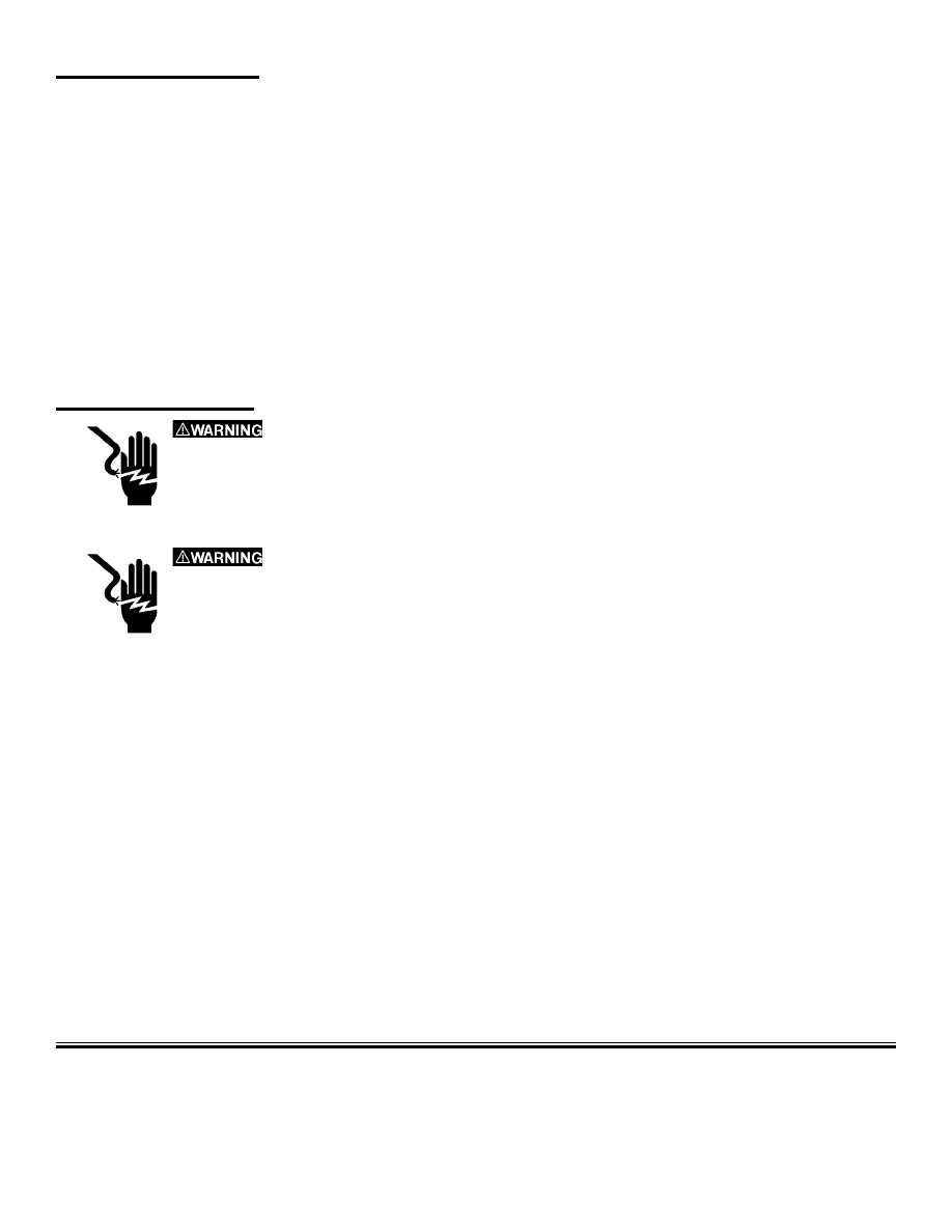
1. Remove the gun liner cover from the wire feeder by removing the two Phillips-head screws.
DO NOT remove the screws at the front of the wire feeder.
2. Remove the nut and the washer from the MIG Gun Connector. Insert the connector, gas hose and wire con-
trol connector through the opening on the front of the welder. Insert the threaded brass section up through
the brass bushing located in the front of the wire drive assembly.
3. The wire liner must be cut to the proper length. Carefully mark the wire liner. Make sure that it is either
flush or extends slightly past the end of the gun liner cover (the end closest to the drive rollers).
DO NOT cut the liner too short!
4. Remove the MIG Gun Connector. Cut the MIG gun liner
with a sharp pair of wire cutters. Make sure the cut is
straight, as close to the drive roller as possible without
touching and there are no rough edges left on the wire liner.
Be careful. DO NOT smash the liner.
5. Re-install the MIG Gun Connector. Attach the machine
power connection cable, the washer and the nut. Tighten the
nut snugly. DONOT overtighten. Plug in the wire control
connector and the gas hose to the appropriate fixed connec-
tion on the machine.
NEVER look at an electric arc without
eye protection. The arc rays can injure the eyes per-
manently. ALWAYS use a protective shield any other
protection mask or welding helmet.
Figure 1: Feet and Handle Installation
Figure 2: MIG Gun Installation
9
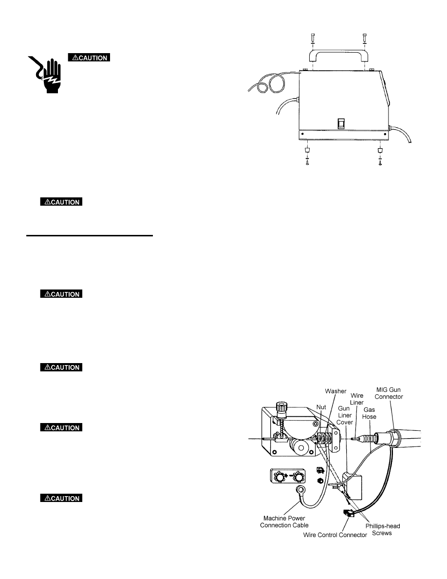
INSTALLATION OF THE WELDING WIRE
The power source is supplied with a spool of .030 MIG Welding Wire. Install the wire into the feeding system
by following the instructions below and referring to Figure 3. MIG (GMAW) welding applications require
argon shielding gas.
Remove the contact tip and gun nozzle from the MIG gun before starting this pro-
cedure.
1. Loosen the nut of the spool holder (brake drum). Remove the spring and the external ring.
2. Remove the plastic protection from the spool. Place it on the spool holder again. Mount the external ring, the
spring and the plastic lock nut again. These parts form the braking system for the wire spool. Tighten nut to
appropriate tightness. Excessive pressure strains the wire feeding motor. Too little pressure does not allow
the immediate stop of the wire spool at the end of the welding.
3. Loosen and lower the plastic knob. Release the upper roll of the feeder. Extract any wire remaining in the
torch liner from an earlier roll of wire.
4. When the wire is disconnected, grasp it with pliers so that it cannot exit from the spool. If necessary,
straighten it before inserting it in the wire input guide. Insert the wire on the lower roll and in the torch
liner.
Keep the torch straight. When feeding a new wire through the liner, make sure
the wire is cut cleanly (no burrs or angles) and that at least 2” from the end is straight (no
curves). Failure to follow these instructions could cause damage to the liner.
5. Lower the upper roll and the knob. Tighten slightly. If tightened too much, the wire gets locked and could
cause motor damage. If not tightened enough, the rolls will not feed the wire.
Figure 3: Wire Installation
10
When changing the wire diameter being used, or replacing the wire feed roll, be
sure that the correct groove for the wire diameter selected is inside, closest to the machine.
The wire is driven by the inside groove. Feed rolls are marked on the side identifying the
nearest groove. Feed rolls installed on the FP 120, FP 130, FP 160 are marked "0.6" on one
side. When this side is inside, closest to the machine, the groove is suitable for use with
0.023" (0.6mm) hard wire. The other side is marked "0.8". When this side is inside, closest
to the machine, the groove is suitable for use with 0.030" (0.8mm) hard wire and 0.035"
(0.9mm) flux core wire.
6. Connect the power supply cable to the power output line. Turn on the switch. Press the torch switch. The
wire fed by the wire feeding motor at variable speed must slide through the liner. When it exits from the
torch neck, release the torch switch. Turn off the machine. Mount the contact tip and the nozzle.
The rolls, when moving, may crush the fingers. Periodically, check the rolls.
Replace them when they are worn and compromise the regular feeding of the wire.
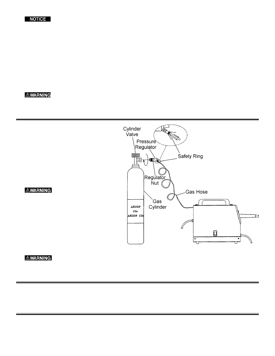
GAS CYLINDER AND REGULATOR CONNECTION
1. Assemble the pressure regulator to the
cylinder. Tighten the regulator nut, but DO
NOT overtighten. Overtightening can dam-
age the cylinder valve.
2. Connect the gas hose to the regulator using
a safety ring.
3. Open the cylinder valve. Push the torch trig-
ger to ensure that the gas is flowing through
the torch.
Cylinders are highly pres-
surized. Handle with care. Serious
accidents can result from improper
handling or misuse of compressed gas
cylinders. DO NOT drop the cylinder,
knock it over, expose it to excessive
heat, flames or sparks. DO NOT strike
it against other cylinders. Contact your
gas supplier for more information about
the use and handling of cylinders.
DO NOT use the cylinder if you find oil, grease or damaged parts. Inform your
gas supplier of this condition immediately.
MIG GUN
We recommend to periodically check the contact tips and the nozzle. These parts must be clean and not worn.
Replace the torch liner when the wire does not run smoothly.
MIG WELDING
In MIG (GMAW) welding, a continuously fed metal electrode is melted into a welding pool at constant and
controlled speed. The torch is connected to the positive pole while the ground cable is connected to the nega-
Figure 4: Gas Cylinder and Regulator Connection
11

tive pole. When the wire is fed and touches the workpiece, an electric arc is produced. The arc melts the wire
that is deposited on the workpiece.
MIG welding uses a steel coppered wire as an electrode and an inert gas (CO
2
, CO
2
/Argon mix or pure Argon)
for protection of the weld pool.
The wire can be one of three types:
1. Solid wire - ALWAYS used with a protective gas.
2. Cored wire - Has a core of mineral powders to enhance its characteristics and is used with gas.
3. Gasless cored-wire - Has a core of mineral powders that, when burning, release the protective gas for the arc.
ALWAYS used without gas.
The welding unit consists of a DC power source, a wire-feeder, a torch, a ground clamp and a pressure regula-
tor. Each power source has a 4-position switch used to regulate the welding current, a potentiometer regulating
the wire speed, a potentiometer with a switch and a timer to set the spot welding time (for those models where
this feature is provided). Welding current and wire speed are set considering the thickness of the material to be
welded. The thicker the material, the higher welding current and the higher the wire speed. The wire speed can
be fine tuned during welding for better results.
ONLY experienced personnel should use the power sources.
GASLESS WELDING
In gasless welding the torch is connected to the negative pole and the ground cable to the positive pole. In gas
welding, the shielding gas is used to protect the weld pool from oxidation and porosity. In gasless welding, this
protection is given by a special wire called “flux cored wire.” This technique simplifies the use of these
machines.
ADVANTAGES OF GASLESS WELDING
1. There is no need for gas cylinders.
2. Welding outdoors is easier because there are fewer chances that wind blows away the shielding gas.
3. Welding time is about 50% less compared to the normal stick electrode welding.
4. The learning time for the operator is very short.
5. Minimum waste of welding material.
6. Most important, this process is faster and more efficient.
7. Less heat, less distortion.
8. Possible to weld thin materials.
PREPARATION FOR WELDING
Cylinders are highly pressurized. Handle with care. Serious accidents can result
from improper handling or misuse of compressed gas cylinders. DO NOT drop the cylinder,
knock it over, expose it to excessive heat, flames or sparks. DO NOT strike it against other
cylinders. Contact your gas supplier for more information about the use and handling of cylin-
ders.
DO NOT use the cylinder if you find oil, grease or damaged parts. Inform your
gas supplier of this condition immediately.
1. Connect the FP-160 welding machine to a 230V, 60 Hz line. Connect the FP-120 or FP-130 to a 120V, 20
AMP, 60 Hz line.
IMPORTANT
12
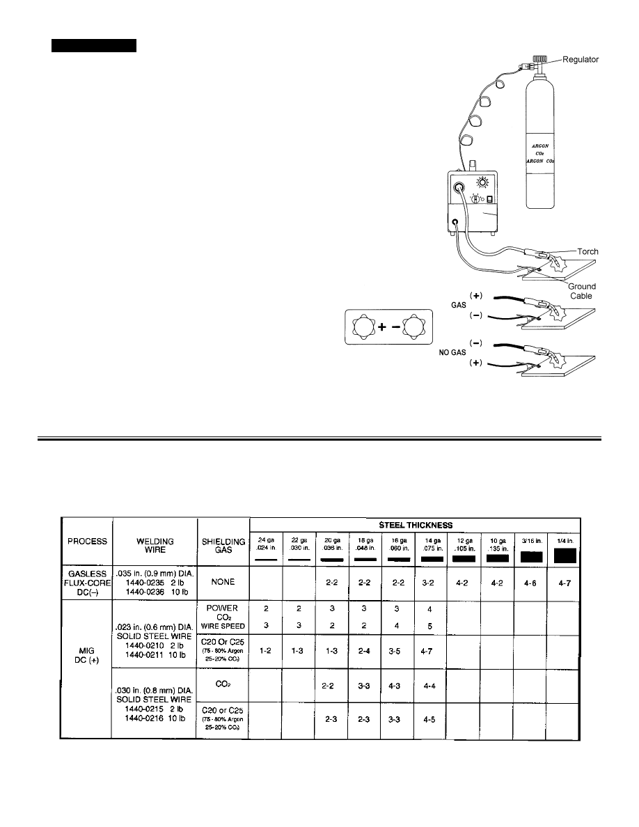
2.
Make sure that the polarity of torch
and ground cable is correctly set. For gasless welding,
the ground cable must be connected to the positive ter-
minal (+), while the torch must be connected to the neg-
ative terminal (-) (see Figure 4).
3. Connect the ground cable to the workpiece. Make sure
that the contact is good.
4. Make sure that the wire-feeding roll is correctly posi-
tioned (groove matching the wire diameter). Note that
each roll has two grooves. One is marked “.023”/0.6
mm” and the other is marked “.030”/0.8 mm.”
5. This unit comes with a preset regulator so there is no
need to adjust the gas flow.
WELDING PROCEDURES
1. Your welding power source has four positions for the regulation of the current in the various conditions. The
choice of the position for the welding is determined by the thickness of the material to weld.
2. Refer to Table 1 for the adjustment of the power source.
IMPORTANT
Figure 5: Polarity Preparation
13
Table 1:Approximate Settings for Welding

REPLACEMENT OF THE WIRE SPOOL
The welding power source is supplied with a mini wire spool of about 0.5 Kg of 0.024” (0.6mm) diameter
wire. When the wire spool is finished it can be replaced with a wire spool of 2 lbs. or 10 lbs.
The wire is pushed by a roll which is moved by a series of mechanisms. The roll has two grooves, one marked by 0.035” (0.9
mm) and the other marked by 0.023” (0.6 mm). It is very important to use the correct groove as explained in “Preparation for
Welding” on page 12. Otherwise, the wire will not feed regularly or it will be crushed. Make sure that the torch tip matches
with the wire diameter. Your welding power source is supplied with a torch, complete with tip, for the wire included with the
power source. For all the other wire spools mount a tip that matches with the wire diameter.
Refer to Figure 3 on page 10. Follow the procedure described in “Installation of the Welding Wire” on page 10
for the replacement of the wire spool.
WELDING TIPS
1. Keep the torch handle with a 45º angle with respect to the workpiece. Maintain the nozzle about 1/4” (0.6
mm) from the surface.
2. Move the torch handle with prudence and steadiness.
3. Avoid welding in areas with too much draft. Too much draft blows away the shielding gas from the weld
pool and mainly causes porosity in the weld.
4. Keep the wire and its cover clean. DONOT use rusted wire.
5. Avoid sharp bends and kinks on the MIG gun cable.
6. If possible, clean the wire liner with compressed air when replacing the wire spool.
7. Periodically, remove the dust using low pressure air or nitrogen (2-3 bar/30-45 PSI) from the inside of the
power source, to assure adequate heat dissipation from power source during operation.
SPOT WELDING
Spot welding is possible by replacing the welding nozzle with a spot welding nozzle. You can buy the spot
welding nozzle from any supplier of Firepower Welding Systems. Spot welding can be performed on carbon
steel sheets of 18 gauge thickness.
Place the spot welding nozzle on the upper sheet. Push firmly on the torch, being sure that the top sheet is in
contact with the bottom one. Press and hold the trigger. Welding will stop automatically after the pre-selected
time. For spot welding, the machine must be set at maximum current and maximum wire speed. We recom-
mend 0.030” welding wire.
ADJUSTMENT OF THE POWER SOURCE
Set the voltage. Use the correct “stick out.” The wire “stick out” is the dis-
tance between the contact tip and the workpiece. The wire “stick out” (some-
times improperly called the arc length) should remain in the 0.197”-0.394”
(5mm-10mm) range to obtain the best welding (and sound) performance.
1. Position the voltage switch in the desired position (see Table 1). Select
lower position for lower thickness and higher settings for higher thickness.
2. Adjust the wire speed. Start using a trial metal sheet thoroughly cleaned of
layers of rust or paint. Connect the ground cable to the workpiece. Adjust
the wire speed at the high setting. Press the torch switch.
Figure 6: Power Source
14

The torch switch must be pressed thoroughly to perform its three functions: gas
flow, wire feed and welding current.) Start welding and decrease the wire speed gradually.
Continue to decrease the wire speed and listen to the sound. The sound will change from a
crackling noise to a regular and strong buzzing (similar to the sound of frying bacon). This
buzzing sound indicates the correct wire speed for the workpiece being welded. When the
current regulation is changed, reset the wire speed. ALWAYS start from a higher wire speed.
This operation prevents damage to the contact tip during welding. During welding, keep the
torch at a 45º angle from the workpiece. Keep the nozzle 1/4” to 1/2” from the workpiece.
ADDITIONAL SAFETY INFORMATION
Make sure you read and understand all of the information and instructions contained in this manual BEFORE
proceeding.
The National Electrical Code, Occupational Safety and Health Act (OSHA) regulations, local industrial codes
and local inspection requirements also provide a basis for equipment installation, use and service.
For additional information concerning welding safety, refer to the following standards and comply with them
as applicable.
• ANSI Standard Z49.1 - SAFETY IN WELDING AND CUTTING - obtainable from the American Welding
Society, 2051 N.W. 7th St. Miami, FL 33125 (305) 443-9353.
• ANSI Standard Z87.1 - SAFE PRACTICE FOR OCCUPATION AND EDUCATIONAL EYE AND FACE
PROTECTION - obtainable from the American National Standards Institute, 1430 Broadway, New York, NY
10018.
• NFPA Standard SIB - CUTTING AND WELDING PROCESSES - obtainable from the National Fire
Protection Association, 470 Atlantic Avenue, Boston, MA 02210.
• CGA Pamphlet P-I - SAFE HANDLING OF COMPRESSED GASSES IN CYLINDERS - obtainable from
the Compressed Gas Association, 5005th Avenue, New York, NY 10038.
• OSHA Standard 29 CFR, Part 1910, Subpart 0. - WELDING, CUTTING AND BRAZING - obtainable from
your state OSHA office.
• CSA Standard W117.2 - CODE FOR SAFETY IN WELDING AND CUTTING - obtainable from Canadian
Standards Association, 178 Rexdale Blvd., Rexdale, Ontario Canada M9W 1R3.
• American Welding Society Standard A6.0 - WELDING AND CUTTING CONTAINERS WHICH HAVE
HELD COMBUSTIBLES - obtainable from the American Welding Society, 2051 N.W. 7th St., Miami, FL
33125 (305) 443-9353.
15

P
ROBLEM
1. Dirty, porous or brittle weld.
2. Arc works but is not feeding wire.
3. When trigger pulled, there is no wire
feed, weld output or gas flow.
Fan does not operate.
4. Wire feeding, but there is no arc.
5. Fan operates normally, but when gun
trigger pulled, there is no wire feed,
weld output or gas flow.
6. Non-penetrating weld or low output.
7. Wire is birdnesting at the drive roller.
8. Wire burns back to contact tip.
9. Workpiece clamp and/or cable gets
hot.
10. Gun nozzle arcs to work surface.
11. Wire pushes torch back from the
workpiece.
12. Wire sticks onto the contact tip.
P
OSSIBLE
C
AUSE
Plugged welding nozzle.
Faulty wire speed control assembly.
No tension on the drive roller.
Faulty drive motor (very rare).
Incorrect voltage.
No power.
Circuit breaker in off position.
Bad ground or loose connection.
Bad connection to gun or faulty gun.
Faulty trigger on gun.
Faulty transformer (rare).
Exceeded duty cycle: thermal protector
has opened.
Loose connection inside machine.
Too long or improper extension cord.
Wrong size wire.
Poor ground connection.
Wrong size contact tip.
Loose Gun connection or faulty gun
assembly.
Too much tension on drive roller.
Gun liner worn or damaged.
Contact tip is clogged or damaged.
Liner is stretched or is too long.
Gun liner is worn or damaged.
Wrong size contact tip.
Contact tip clogged or damaged.
Liner is stretched or is too long.
Bad connection from cable to clamp.
Slag buildup inside nozzle or nozzle is
shorted.
Excessive wire speed.
Low wire feeding.
R
EMEDY
Clean or replace welding nozzle.
Replace wire speed control assembly.
Adjust the drive tension.
Replace drive motor.
Check for correct voltage.
Confirm power switch is on.
Reset circuit breaker.
Check ground and connections. Tighten
as necessary.
Check connection to gun or replace gun.
Replace trigger.
Replace transformer.
Allow welder to cool at least 10 minutes.
Maintain appropriate duty cycle.
Blow inside machine out with com-
pressed air. Clean and tighten all connec-
tions.
See extension cord use in this manual.
Use correct size welding wire.
Reposition clamp. Check cable to clamp
connection.
Use correct size contact tip.
Tighten gun or replace gun.
Adjust the drive tension.
Replace gun liner.
Replace contact tip.
Trim liner to proper length.
Replace gun liner.
Use correct size contact tip.
Replace contact tip.
Trim liner to proper length.
Tighten connection or replace cable.
Clean or replace nozzle as needed.
Decrease wire speed.
Increase wire speed.
TROUBLESHOOTING INFORMATION
Use this chart to assist you in resolving common problems you may encounter. These are not all of the possible
solutions.
16

GENERAL OPERATING TIPS
Contact tips and nozzles should be cleaned frequently. Spatter buildup may cause bridging between nozzle and
tip.This could cause electrical shorting between the nozzle and work piece as well as poor or improper gas flow.
Regularly inspect the conductor tube, handle, cable hose, and other parts of the MIG gun for abrasion, cuts, or
undue wear. Replace or repair any parts found deficient.
TROUBLESHOOTING GUIDE FOR FIREPOWER FP-200 MIG GUN
17
P
ROBLEM
Wire feed inconsistent or not smooth.
Mig-Gun is running hot.
Porous weld.
P
OSSIBLE
C
AUSE
1. Loose contact tip or diffuser.
2. Excessively worn contact tip.
3. Spatter buildup on end of contact tip.
4. Sharp bends or kinks in conduit.
5. Dirty or plugged wire liner.
6. Conduit pulled back from diffuser.
7. Machine improperly adjusted.
1. Loose contact tip or diffuser.
2. Loose power connections.
3. Loose or undersize ground cable or
ground clamp.
4. Operating gun above recommended
amperage rating.
1. Poor or improper gas flow.
2. Dirty or contaminated wire.
3. Base metal contaminated.
C
ORRECTIVE
A
CTION
1. Tighten contact tip and diffuser plier-
tight.
2. Replace contact tip.
3. Clean or replace contact tip.
4. Straighten or replace conduit.
5. Replace wire liner.
6. Reposition conduit and tighten front
set screw.
7. Reset machine as per machine and
wire manufacturers' recommendations.
1. Tighten contact tip and diffuser plier-
tight.
2. Inspect complete gun for loose con-
nections and repair.
3. Tighten or replace as required.
4. Re-adjust machine to correct setting
for size of gun being used.
1. Check gas flow out of gun nozzle.
Check for leaks or restrictions in gas
hoses and connections.
2. Change wire.
3. Replace base metal.

FP-200 WIRE LINER REPLACEMENT
To remove the wire liner:
1. Lay the MIG gun out on a table or on the floor in a straight line. Make sure the gun is fully extended and all
twists in the cable are removed.
2. Remove the nozzle, diffuser, contact tip and the left gun handle case.
3. Unscrew the wire liner stop from the rear connector plug.
4. Remove the wire liner with a twisting motion.
To install the wire liner:
1. Uncoil the conduit and lay it in a straight line. Insert the wire liner into the rear connector plug. Push the
wire liner into the gun with short strokes. If the wire liner hangs up, twist the wire liner counterclockwise or
gently whip the cable while applying pressure to the wire liner.
2. When the wire liner clears the cable into the handle - guide the wire liner along the valve body and into the
conductor tube. Continue to install the wire liner until the wire liner extends at least 2" past the end of the
conductor tube.
3. Install and tighten the wire liner stop, then trim the wire liner 1 3/16" /30mm from the end of the stop.
4. Reinstall the left handle case.
5. Trim the wire liner extending from the conductor tube 13/16"/20,6mm from the end of the conductor tube.
6. File the cut wire liner end to remove burrs that could interfere with wire feeding or catch on the diffuser.
7. Replace the diffuser and contact tip. Install and tighten the nozzle.
8. The MIG gun is now ready to be reinstalled on the feeder.
18
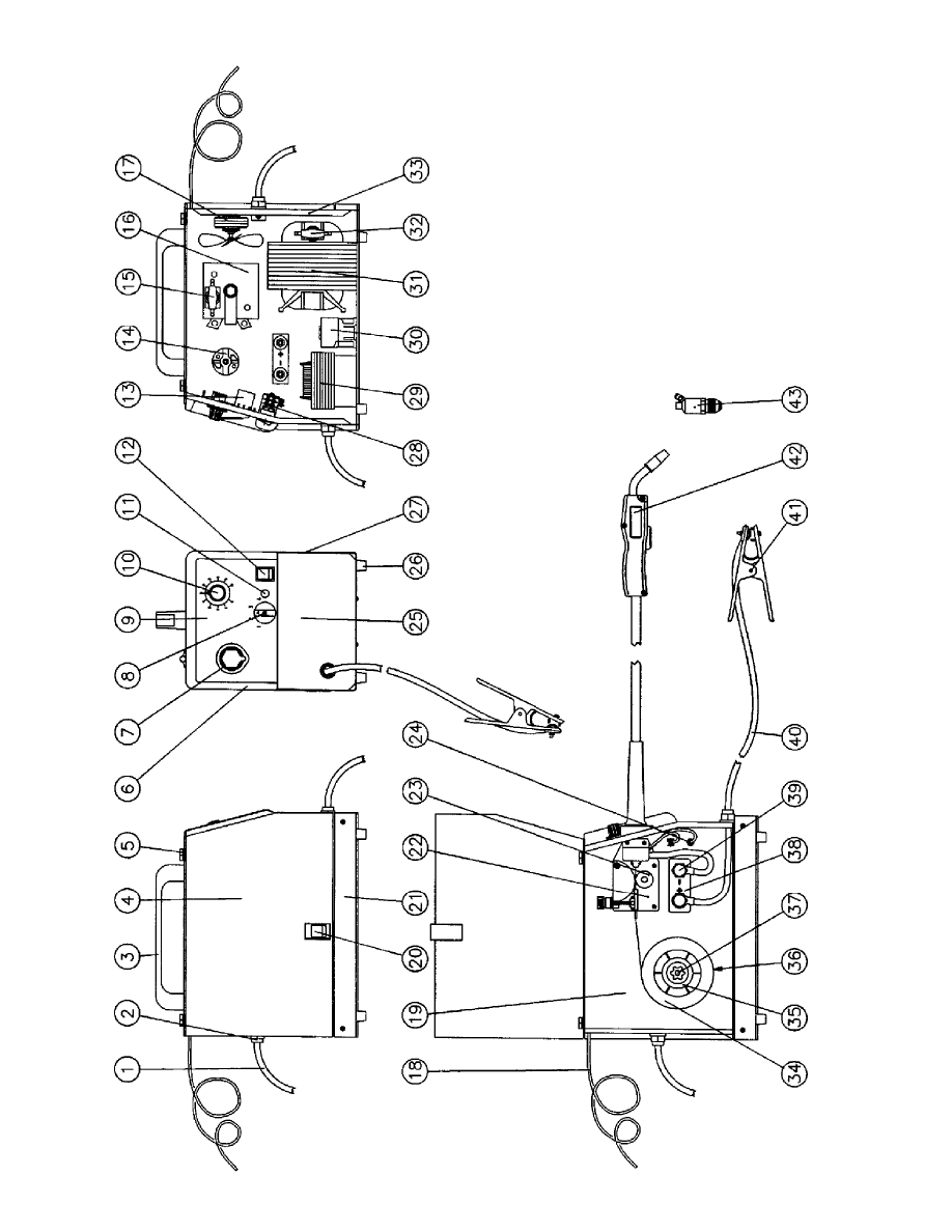
Figur
e
8:
FP
120
19

ITEM
N
O.
P
AR
T
NO.
DESCRIPTION
Q
TY
.
1
1
444-0433
INPUT
PO
WER
CABLE
1
2
1
444-0428
CABLE
CLAMP
2
3
1
444-0473
HANDLE
1
4
1444-0474
SIDE
P
ANEL
MIG
100
FP
1
5
1
444-0435
PLASTIC
HINGE
FOR
SIDE
P
ANEL
2
6
1
444-0476
FR
ONT
P
ANEL
FRAME
1
7
1
444-0477
T
ORCH
GR
OMMET
1
8
1
444-0478
SWITCH
KNOB
1
9
1
444-0479
FR
ONT
P
ANEL
ADHESIVE
PLA
TE
1
10
1444-0480
PO
TENTIOMETER
KNOB
1
11
1444-0481
ORANGE
PILO
T
LAMP
110V
1
12
1444-0482
GREEN
PILO
T
LIGHT
SWITCH
1
13
1444-0483
P
.C.
BO
ARD
1
14
1444-0484
WIRE
FEEDING
MO
T
OR
24V
1
15
1444-0456
THERMOST
A
T
1
16
1444-0432
RECTIFIER
1
17
1444-0486
COMPLETE
F
AN
1
18
1444-0487
GAS
HOSE
1
19
1444-0488
DIVIDING
P
ANEL
1
20
1444-0426
DOOR
LA
TCH
1
21
1444-0490
LO
WER
P
ANEL
1
22
1444-0491
BLA
CK WIRE
FEEDER
1
23
1444-0427
WIRE
FEED
R
OLL
1
24
1444-0493
INTERMEDIA
TE
COUPLER
FOR
GAS
HOSE
1
25
1444-0494
FR
ONT
P
ANEL
1
26
1444-0495
PLASTIC
FOO
T
4
27
1444-0496
UPPER
P
ANEL
1
28
1444-0497
SWITCH
1
29
1444-0457
CHOKE
1
30
1444-0498
CONT
A
C
T
O
R
1
ITEM
N
O.
DESCRIPTION
QTY
.
31
1444-0458
TRANSFORMER
1
32
1444-0470
THERMOST
A
T
1
33
1444-0499
B
A
CK
P
ANEL
1
34
1444-0500
MILD
STEEL WIRE
REEL
1
35
1444-0430
SPOOL
HOLDER
RET
AINING
RING
1
36
1444-0429
FIXED
SPOOL
HOLDER
D.16-50
1
37
1444-0431
SPOOL
HOLDER
KNOB W/NUT0
1
38
1444-0504
GAS/NO
GAS
CHANGE
BO
ARD
1
39
1444-0505
PLASTIC
KNOB
2
40
1
444-0725
GR
OUND
CABLE
1
41
1
443-0025
GR
OUND
CLAMP
1
42
1
444-0405
FP-200
T
ORCH
1
43
0387-1232
GAS
REGULA
T
OR
WITHOUT
GA
UGE
1
(Note:
Must
replace.
Repair
parts
not
a
v
ailable)
FP
120
P
A
R
TS
LIST
20
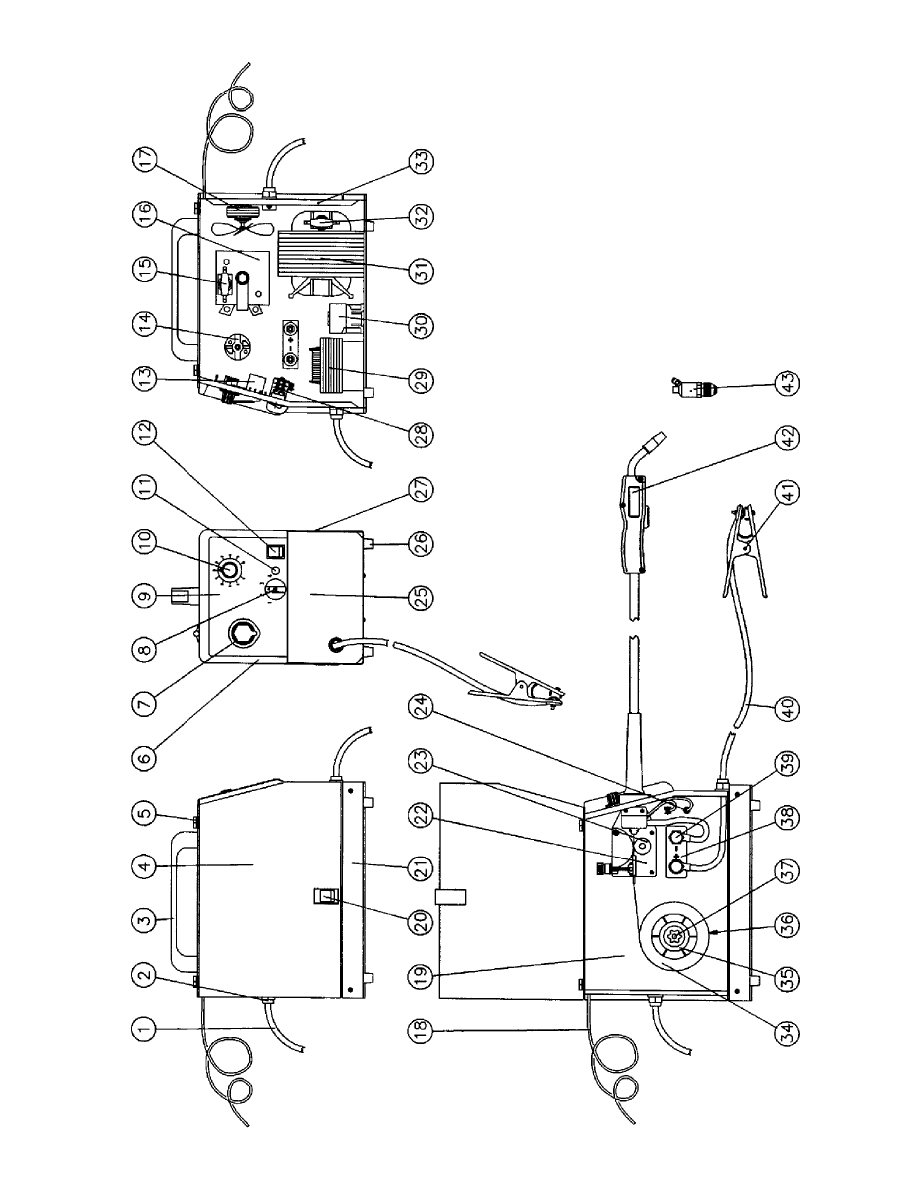
Figur
e
9:
FP
130
21

ITEM
N
O.
DESCRIPTION
Q
TY
.
1
1
444-0433
INPUT
PO
WER
CABLE
1
2
1
444-0428
CABLE
CLAMP
FOR
HOLE
2
3
1
444-0473
HANDLE
1
4
1444-0474
SIDE
P
ANEL
1
5
1
444-0435
PLASTIC
HINGE
FOR
SIDE
P
ANEL
2
6
1
444-0476
FR
ONT
P
ANEL
FRAME
1
7
1
444-0477
T
ORCH
GR
OMMET
1
8
1
444-0478
SWITCH
KNOB
1
9
1
444-0479
FR
ONT
P
ANEL
ADHESIVE
PLA
TE
1
10
1444-0480
PO
TENTIOMETER
KNOB
1
11
1444-0481
ORANGE
PILO
T
-LAMP
110V
1
12
1444-0482
GREEN
PILO
T
-LIGHT
SWITCH
1
13
1444-0483
P
.C.
BO
ARD
1
14
1444-0484
WIRE
FEEDING
MO
T
O
R
1
15
1444-0443
THERMOST
A
T
1
16
1444-0432
RECTIFIER
1
17
1444-0486
COMPLETE
F
AN
1
18
1444-0487
GAS
HOSE
1
19
1444-0488
DIVIDING
P
ANEL
1
20
1444-0426
DOOR
LA
TCH
1
21
1444-0490
LO
WER
P
ANEL
1
22
1444-0491
BLA
CK WIRE
FEEDER
1
23
1444-0427
WIRE
FEED
R
OLL
1
24
1444-0493
INTERMEDIA
TE
COUPLER
FOR
GAS
HOSE
1
25
1444-0494
FR
ONT
P
ANEL
1
26
1444-0495
PLASTIC
FOO
T
4
27
1444-0496
UPPER
P
ANEL
1
28
1444-0497
SWITCH
1
29
1444-0461
CHOKE
1
30
1444-0498
CONT
A
C
T
O
R
1
ITEM
N
O.
DESCRIPTION
Q
TY
.
31
1444-0462
TRANSFORMER
1
32
1444-0470
THERMOST
A
T
1
33
1444-0499
B
A
CK
P
ANEL
1
34
1444-0500
MILD
STEEL WIRE
REEL
1
35
1444-0430
SPOOL
HOLDER
RET
AINING
RING
1
36
1444-0429
FIXED
SPOOL
HOLDER
1
37
1444-0431
SPOOL
HOLDER
KNOB
W/NUT
1
38
1444-0504
GAS/NO
GAS
CHANGE
BO
ARD
1
39
1444-0505
PLASTIC
KNOB
2
40
1
444-0725
GR
OUND
CABLE
1
41
1
443-0025
GR
OUND
CLAMP
1
42
1
444-0405
FP-200
T
ORCH
1
43
0387-1232
GAS
REGULA
T
O
R W/OUT
GA
UGE
1
(Note:
Must
replace.
Repair
parts
not
a
v
ailable)
FP
130
P
A
R
TS
LIST
22
Figur
e
10:
FP
160
23

ITEM
N
O.
DESCRIPTION
Q
TY
.
1
1
444-0463
INPUT
PO
WER
CABLE
1
2
1
444-0428
CABLE
CLAMP
2
3
1
444-0473
HANDLE
1
4
1444-0474
SIDE
P
ANEL
1
5
1
444-0435
PLASTIC
HINGE
FOR
SIDE
P
ANEL
2
6
1
444-0478
FR
ONT
P
ANEL
FRAME
1
7
1
444-0477
T
ORCH
GR
OMMET
1
8
1
444-0478
SWITCH
KNOB
1
9
1
444-0479
FR
ONT
P
ANEL
ADHESIVE
PLA
TE
1
10
1444-0480
PO
TENTIOMETER
KNOB
1
11
1444-0464
ORANGE
PILO
T
-LAMP
220V
1
12
1444-0482
GREEN
PILO
T
-LIGHT
SWITCH
1
13
1444-0465
P
.C.
BO
ARD
1
14
1444-0484
WIRE
FEEDING
MO
T
O
R
1
15
1444-0443
THERMOST
A
T
1
16
1444-0466
RECTIFIER
1
17
1444-0467
F
A
N
1
18
1444-0487
GAS
HOSE
1
19
1444-0488
DIVIDING
P
ANEL
1
20
1444-0426
DOOR
LA
TCH
1
21
1444-0490
LO
WER
P
ANEL
1
22
1444-0491
WIRE
FEEDER
1
23
1444-0427
WIRE
FEED
R
OLL
1
24
1444-0493
INTERMEDIA
TE
COUPLER
FOR
GAS
HOSE
1
25
1444-0494
FR
ONT
P
ANEL
1
26
1444-0495
PLASTIC
FOO
T
4
27
1444-0496
UPPER
P
ANEL
1
28
1444-0497
SWITCH
1
29
1444-0468
CHOKE
1
30
1444-0498
CONT
A
C
T
O
R
1
ITEM
N
O.
DESCRIPTION
QTY
.
31
1444-0469
TRANSFORMER
1
32
1444-0470
THERMOST
A
T
1
33
1444-0499
B
A
CK
P
ANEL
1
34
1444-0500
MILD
STEEL WIRE
REEL
1
35
1444-0430
SPOOL
HOLDER
RET
AINING
RING
1
36
1444-0429
FIXED
SPOOL
HOLDER
1
37
1444-0431
SPOOL
HOLDER
KNOB W/NUT
1
38
1444-0504
GAS/NO
GAS
CHANGE
BO
ARD
1
39
1444-0505
PLASTIC
KNOB
2
40
1
44-0725
GR
OUND
CABLE
1
41
1
443-0025
GR
OUND
CLAMP
1
42
1
444-0405
FP-200
T
ORCH
1
43
0387-1232
GAS
REGULA
T
OR
WITHOUT
GA
UGE
1
(Note:
Must
replace.
Repair
parts
not
a
v
ailable)
FP
160
P
A
R
TS
LIST
24
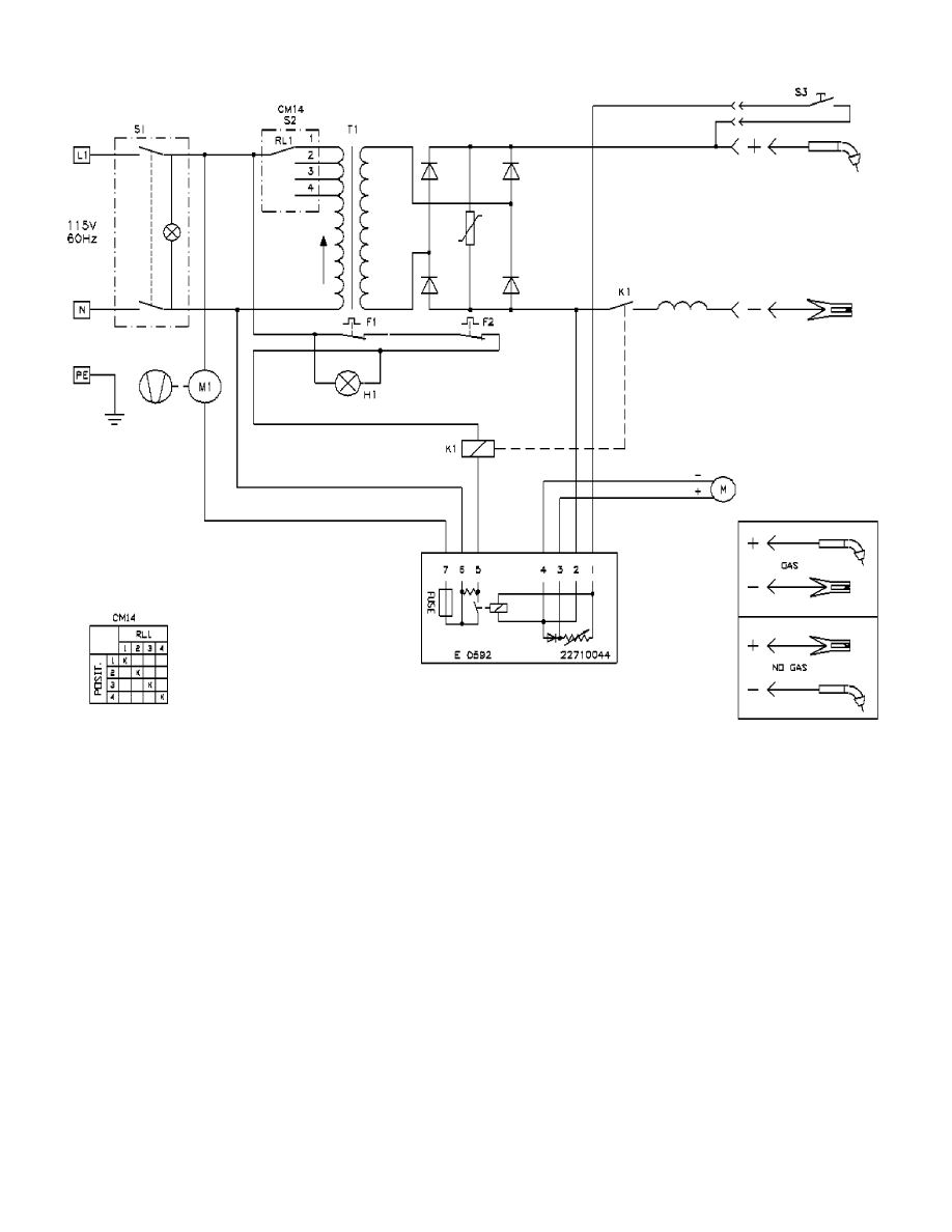
25
Figure 11: FP 120 Wiring Diagram
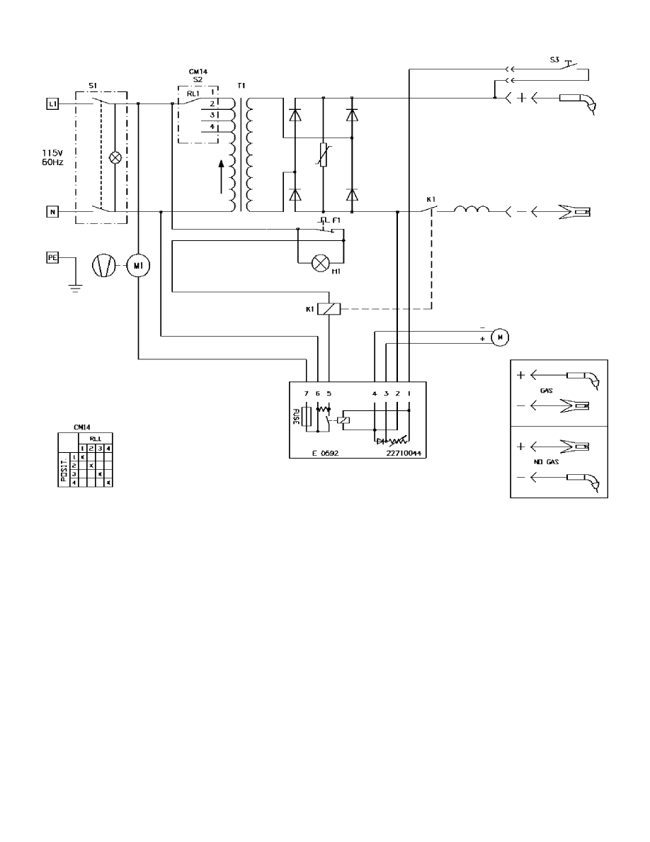
26
Figure 12: FP 130 Wiring Diagram
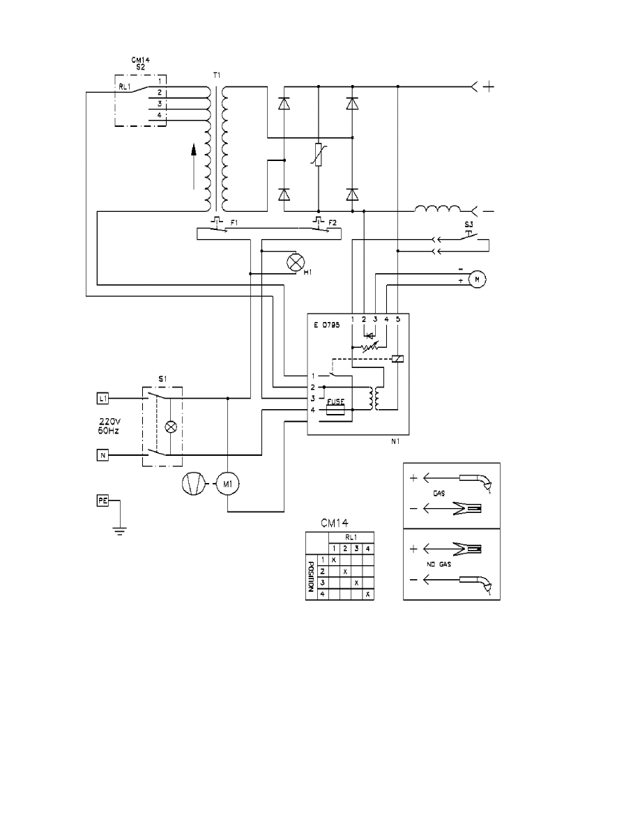
27
Figure 13: FP 160 Wiring Diagram

28
FIREPOWER LIMITED WARRANTY
SCOPE OF LIMITED WARRANTY: Firepower, a division of Thermadyne Industries, Inc. (here-
inafter, "Seller") warrants that its products are free of defects in workmanship or material. If an autho-
rized distributor or the customer of an authorized distributor (hereinafter, collectively, "Purchaser")
who purchases Seller's product, notifies Seller within the time set forth below that the product has a
defect in workmanship or material even though it has been stored, installed, operated, and maintained
in accordance with Seller's specifications, instructions, recommendations and in accordance with rec-
ognized standard industry practice, and the product was not misused, repaired, neglected, altered, or
damaged, the Seller may repair or replace, in its sole discretion, those parts of the product determined
by Seller to be defective in workmanship or material if said defect is not attributable to Purchaser's acts
or omissions.
THIS WARRANTY EXCLUDES ANY WARRANTY OF MERCHANTABILITY, FITNESS
FOR A PARTICULAR PURPOSE, OR OTHER WARRANTY OF QUALITY, WHETHER
EXPRESSED, IMPLIED OR STATUTORY.
LIMITED WARRANTY PERIOD: Except as otherwise limited below, this limited warranty is effec-
tive for twelve months from the date Seller sells the product to an authorized distributor, or for twelve
months after an authorized distributor sells the product to its customer, whichever is longer, except that
in no event will this warranty exceed eighteen months from the date the product is sold from Seller to
an authorized distributor.
Notwithstanding the foregoing,
• Firepower oxygen / acetylene products will be covered by a two-year product replacement warranty
• Firepower plasma cutting equipment will be covered by a one-year (parts & labor) warranty.
• Firepower electric welding machines will be covered by the Firepower 5-2-1 limited warranty.
• 5 years on the transformer
• 2 years on the welding unit
• 1 year on the MIG gun
• Firepower engine-driven welding machines will be covered by a one-year (parts & labor) warranty.
Engines will be covered by the manufacturer's warranty.
• Firepower ADF (auto-darkening) welding helmets will be covered by a one-year warranty. Any
ADF helmet claims must be made directly to Jackson / Morsafe products, Belmont, MI, 800-253-
7281.
• Firepower welding electrodes, MIG (& flux cored) wire, and brazing rods, although manufactured to
AWS Class specifications, are considered perishable items. As, such, these products are sold "as is"
and "with faults" and without warranty, either express or implied, including the warranties of mer-
chant ability and fitness for a particular purpose.
• Products used in rental applications are warranted for one year from the date sold by the Seller to an
authorized distributor, without regard to when they were later sold by the authorized distributor.

U.S.A.
International
Canada
Europe
Asia/Pacific PTE, Ltd.
Mexico
Customer Service
Customer Service
Customer Service
Europa Building
Hillview House Unites 401-403 Calle de Zaragoza #25
P. O. Box 1007
2070 Wyecroft Road
2070 Wyecroft Road
Chorley North Industrial Park1 Jalan Remaja
Col. Santa Cruze Aloyac
Denton TX 76202-1007
Oakville, Ontario L6L5V6
Oakville, Ontario L6L5V6
Chorley, PR6 7BX, England
Singapore 668662
C.P. 03910 Mexico, D.F.
800-426-1888
Canada
Canada
44-1257-261755
65-763-4022
52-539-3708
FAX 800-535-0557
905-827-9777
905-827-1111
FAX 44-1257-261756
FAX 65-763-5812
FAX 525-539-1547
FAX 905-827-9797
FAX 905-827-3648
Telex (383) 1771300 Achame
Printed in Italy
Form No. 0056-1842
July 2001
© Victor Equipment Company, 2001
WORLD HEADQUARTERS: 101 S. Hanley Road
"
St. Louis, MO 63105
"
314-721-5573
"
FAX 314-721-4822
LIMITED WARRANTY CLAIM METHOD: To make a claim under this warranty, Purchaser must
notify Seller of the details of such claim within thirty days of discovering a defect in material or work-
manship. If the claim is covered by this warranty, Seller will direct Purchaser to return the product to
an authorized warranty repair center. The Seller will not be responsible for transportation costs or
risks of any kind under this warranty. The Purchaser will be responsible for all such transportation
costs and risks.
LIMITATION OF LIABILITY: Seller shall not, under any circumstances, be liable for special, indi-
rect, incidental or consequential damages (regardless of the form of action, whether in contract or in
tort including negligence), including, but not limited to, damage or loss of other property or equip-
ment, loss of profits or revenue, cost of capital, cost of purchased or replacement goods, or claims of
Purchaser for service interruption. In no event will this warranty obligate Seller for any amount
exceeding the price of the goods upon which liability is based. Correction of non-conformities, in the
manner and time provided herein, constitutes fulfillment of all Seller's obligations to Purchaser with
respect to Purchaser's purchase of Seller's product.
This warranty is invalid if the product was sold by non-authorized entities. This warranty is invalid if
replacement parts or accessories were used that in Seller's sole opinion impaired the safety or perfor-
mance of seller's product. This warranty supersedes all previous warranties.
The quality system of the Denton and Abilene, Texas locations of Victor Equipment Company,
Victor de Mexico in Hermosillo, Mexico and Victor de Brazil in Rio de Janeiro, Brazil are regis-
tered by Det Norske Veritas (DNV) to meet the requirements of ISO-9001, 1994.
Wyszukiwarka
Podobne podstrony:
160 Omow wspoldzialanie systemow transportu podczas wytwarzania kwasu solnego w zoladku
Wyklad FP II dla studenta
FP w 08
Wyklad FP V
Wyklad FP IV
FP 8 Wydatki budzetu panstwa ma Nieznany
1 Wprowadzenie do FP
FP ocena rentowności papierów wartościowych
FP gr1 2009, Finanse Publiczne
ZMIANY W JST - FP, IV SEMESTR, 3 semestr
FP 7 i 8, Prawo Finansowe, Wykłady IV rok - projekt, PF - wykłady, wykłady PF - 6 semestr
FP MB Wyklad 4
FP 5
fp-wyk11, UE Katowice FiR, finanse publiczne
PiÂmiennictwo do FP w WSZOP 09-10-05, fizjologia pracy
więcej podobnych podstron