A
t first, there was a lot of excite-
ment over that high-profile
project your ready mix compa-
ny was so proud to have a part
in. Then came the bad news. The cylinder
compressive strength test results are low.
The contractor is blaming your company.
He claims it was bad concrete. You think
otherwise.
To aid the investigation, cores will be tak-
en and tested. Knowing the in-place charac-
teristics of the concrete and how they affect
the measured compressive strength of the
cores can go a long way toward establish-
ing that the low-strength cylinders were not
the result of bad concrete.
In-place strength
Concrete coring is generally deemed nec-
essary by unacceptably low laboratory-
cured or field-cured cylinder strengths.
Therefore, core strengths should be ob-
tained from the in-place concrete that repre-
sents the low cylinder strengths. Unfortu-
nately, in practice, the cores aren’t always
removed from locations in the structure rep-
resented by low cylinder strength results.
Fo r example, if 150 cubi c yards ar e
placed in a wall, ACI 318 “Building Code
Requirements for Reinforced Concrete” re-
quires only one strength test. Concrete for
the one strength test is removed from a
middle portion of a single truck. Assuming
8 cubic yards per ready mix truck, it takes
19 truckloads of concrete to fill the wall.
Because ACI 318 requires that cores be re-
moved from the area in question, that
means locating the suspect concrete from
that one truckload.
If accurate placement records are avail-
able, the area of low strength concrete may
be located and cores removed. However,
choosing core locations based on placement
records does not confirm that the one truck-
load of concrete tested is the only low-
strength concrete in the wall. Although re-
moving cores from a suspected low-strength
area satisfies ACI 318 criteria for sampling,
other locations may need testing.
For instance, the one truckload of suspect-
ed low-strength concrete may actually repre-
sent the quality of concrete in other truck-
loads. Using a nondestructive technique to
locate the suspect truckload of concrete pro-
vides a comparison for locating other poten-
tial low-strength areas.
Occasionally, the contractor determines
the area of suspect concrete by pointing to
an arbitrary location. Alternatively, the test-
ing laboratory may core concrete in a loca-
An under-
standing
of concrete
core test-
ing can be
invaluable
when
in-place
concrete
quality is
questioned
By Bruce A.
Suprenant
Core strength variation
of in-place concrete
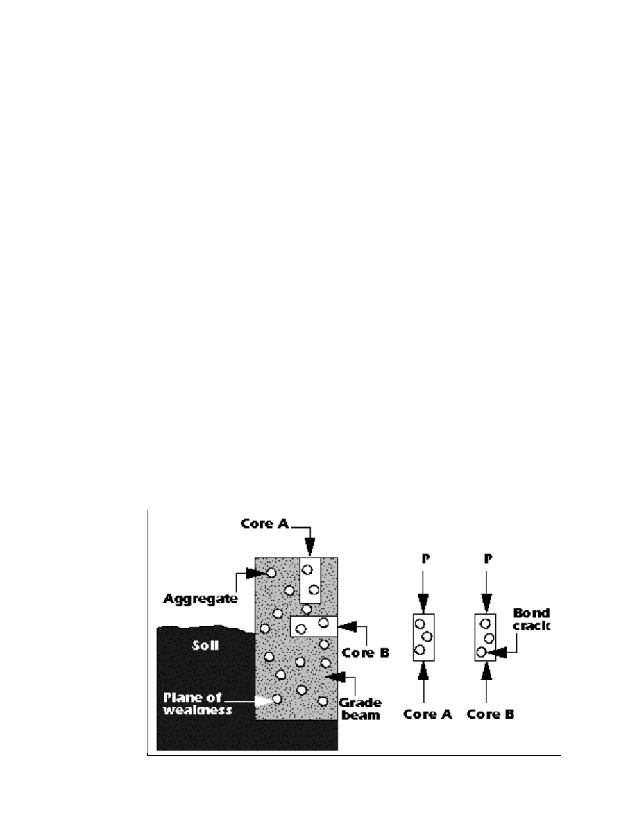
F i g u r e 1 .
Pl a nes of
weakness under coarse
aggregate particles due
to bleeding.
tion accessible to its equipment.
While accurate placement records
are beneficial, verification by a
nondestructive testing technique is
pr ud ent. Id eall y, the engin eer
should be involved in determining
the location for core testing.
Low cylinder strengths may be
due to errors in sampling or testing
and not due to inadequate concrete.
Engineers must decide whether the
low cylinder strength indicates poor
testing, a bad truckload of concrete,
or a bad placement, then, if neces-
sary, plan an appropriate core test-
ing program.
Cores vs. cylinders
Cores do not serve the same pur-
pose as cylinders. Strength of stan-
dard cylinders represents the quality
of concrete delivered. Cylinder com-
pressive strength represents the
quality of concrete batching, mixing,
and transportation, as well as the
sampling, preparation, handling, cur-
ing, and testing of the cylinders.
Strength of cores represents the in-
place concrete strength. In addition
to concrete batching, mixing, and
transportation, core compressive
strengths represent the quality of
placement, consolidation, and cur-
ing, and the techniques for obtaining
and testing cores. Therefore, the re-
lationship between core and cylinder
strength varies because of the char-
acteristics that each specimen repre-
sents.
Coring direction
Cores obtained by drilling in the
direction of concrete casting may
provide a higher strength than cores
obtained by drilling perpendicular
to the direction of casting . The
strength difference due to drilling
direction is generally attributed to
bleeding in fresh concrete, which
creates a weak paste pocket under
coarse aggregate particles (Figure 1).
Because of the bleedwater, the
paste-to-coarse aggregate bond be-
low the aggregate particles may be
w e a k e r .
A load applied parallel to the weak
bond opens a crack, creating a
strength-decreasing flaw. However, a
load applied perpendicular to the
weak bond closes the crack, mini-
mizing the effect of the bleedwater
layer. If this theory holds true, reduc-
ing bleedwater minimizes the effect
of coring direction. Thus, any factor
that affects bleeding, such as the
concrete mix design, mix ingredients,
air content, and placement and con-
solidation techniques, also deter-
mines the strength difference of
cores drilled vertically or horizontal-
ly.
Most slabs and foundations are
cored parallel to the direction of
casting, resulting in no associated
reduction in strength. Walls and
columns are cored perpendicular to
the direction of casting, thus a re-
duction in strength may occur.
The data on the effect of coring
direction is contradictory. It is quite
likely that the compressive strength
of cores drilled horizontally are
stronger than cores drilled vertically.
Practical considerations, however,
like variations in placement, consoli-
dation, and mix variability might ob-
scure a coring direction difference
that is discernible only under pre-
cise control of the mix and con-
struction practices. The current prac-
tice in the industry is to neglect any
effect of coring direction.
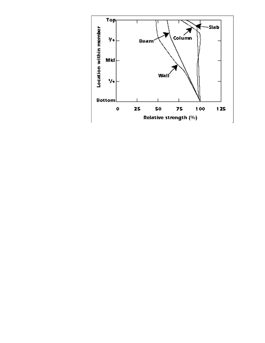
Top-to-bottom strength
variation
It is generally acknowledged that
concrete strength varies within a sin-
gle element. The strength variations
shown in Figure 2 should not be
considered as absolute numbers.
Figure 2 is very useful, however,
when planning a nondestructive sur-
vey to determine the likelihood of a
low-strength cylinder or core loca-
t i o n s .
Laboratory test results indicate two
apparent causes of the strength vari-
ation: strength increase at the bot-
tom attributed to greater static pres-
sures caused by the concrete above
and strength decrease at the top at-
tributed to higher water-cement ra-
tios as a result of bleedwater (Figure
3 ) .
Consolidation
A contractor’s consolidation effort
has a significant effect on concrete
strength. It is estimated that between
5% and 20% of air is entrapped while
placing concrete. Vibrators reduce
the amount of entrapped air by con-
solidating the concrete. The core’s
compressive strength represents the
Figure 2.
Estimated within-member strength variation.
degree of consolidation achieved by
workers and their equipment.
Some state highway departments
studied how the spacing of im-
mersed vibrators affects core com-
pr essive str eng th . On sli pfor m
pavers the vibrators are fixed at a
set spacing. Concrete directly in the
path of the vibrators is consolidated
better than concrete between the
vibrators. Vibrator spacing is cho-
sen based on the radius of influ-
ence, usually 24 inches.
Cores removed from the path of
the vibrator are stronger and denser
than cores removed between vibra-
tors. Cores removed from the bot-
tom are stronger and denser than
those removed from the top. Work
by several highway departments
shows that a reasonable maximum
decrease in a pavement core’s unit
weight compared to the unit weight
of an ASTM cylinder is 4%. This
corresponds to a loss in compres-
sive strength of about 1200 psi.
Effects of curing
The thermal history and curing of
cores is quite different than for stan-
dard cylinders. The structure’s ther-
mal environment might be better or
worse than that provided by labora-
tory curing. Also, most structures
aren’t moist cured like a standard
ASTM cylinder. Field curing is un-
likely to be as good as moist curing.
Field concrete may be subjected
to cold- or hot-weather curing con-
ditions. High temperatures can low-
er concrete strength but lower tem-
peratures could actually produce
stronger concrete at later ages.
The methods for obtaining and
testing a core obscure the effects of
curing. Curing dramatically affects
the concrete surface, but has less of
an effect on the interior concrete.
The outer concrete protects the in-
ner concrete’s humidity and temper-
ature conditioning. When cores are
tested, the restraint of the testing
procedure makes most concrete
cores fail within the middle portion
of the core. Weak outer edges, af-
fected by curing methods, are not
usually represented by the core fail-
ure mode or the resulting test value.
The test results presented indicate
that for vertical members such as
walls and columns, curing had little
effect on core strengths. For slabs,
however, curing is critical to achiev-
ing adequate core strength.
Recommendations for core
locations
For a core drilled perpendicular
to a horizontal surface, ASTM C 42
states, “The location shall be, when
possible, so that its axis is perpen-
dicular to the bed of the concrete
as originally placed and not near
formed joints or obvious edges of a
unit of deposit.” For a core drilled
perpendicular to a vertical surface
or a battered surface, ASTM C 42
states the core “shall be taken from
near the middle of a unit of deposit
when possible and not near formed
joints or obvious edges of a unit of
deposit.”
The Concrete Society Working
Party recommends that “the section
of core to be tested should not in-
clude the top 20%, to a limit of 12
inches, of the lift concerned. The
top 2 inches should not be includ-
ed in any case.” The Nati ona l
Ready Mixed Concrete Association
(NRMCA) r ecommends again st
drilling cores from the top layers of
columns, slabs, walls, or footings.
NRMCA indicates that cores from
the top layer s are 10% to 20%
weaker than cores from the middle
or lower portion. ✥
This article is based on publication
185, “Understanding Concrete
Core Testing,” published by the
National Ready Mixed Concrete
Association (NRMCA). For more in-
formation or to order a copy, con-
tact NRMCA, 900 Spring St., Silver
Spring MD 20910 (phone: 301-
587-1400, fax: 301.585.4219).
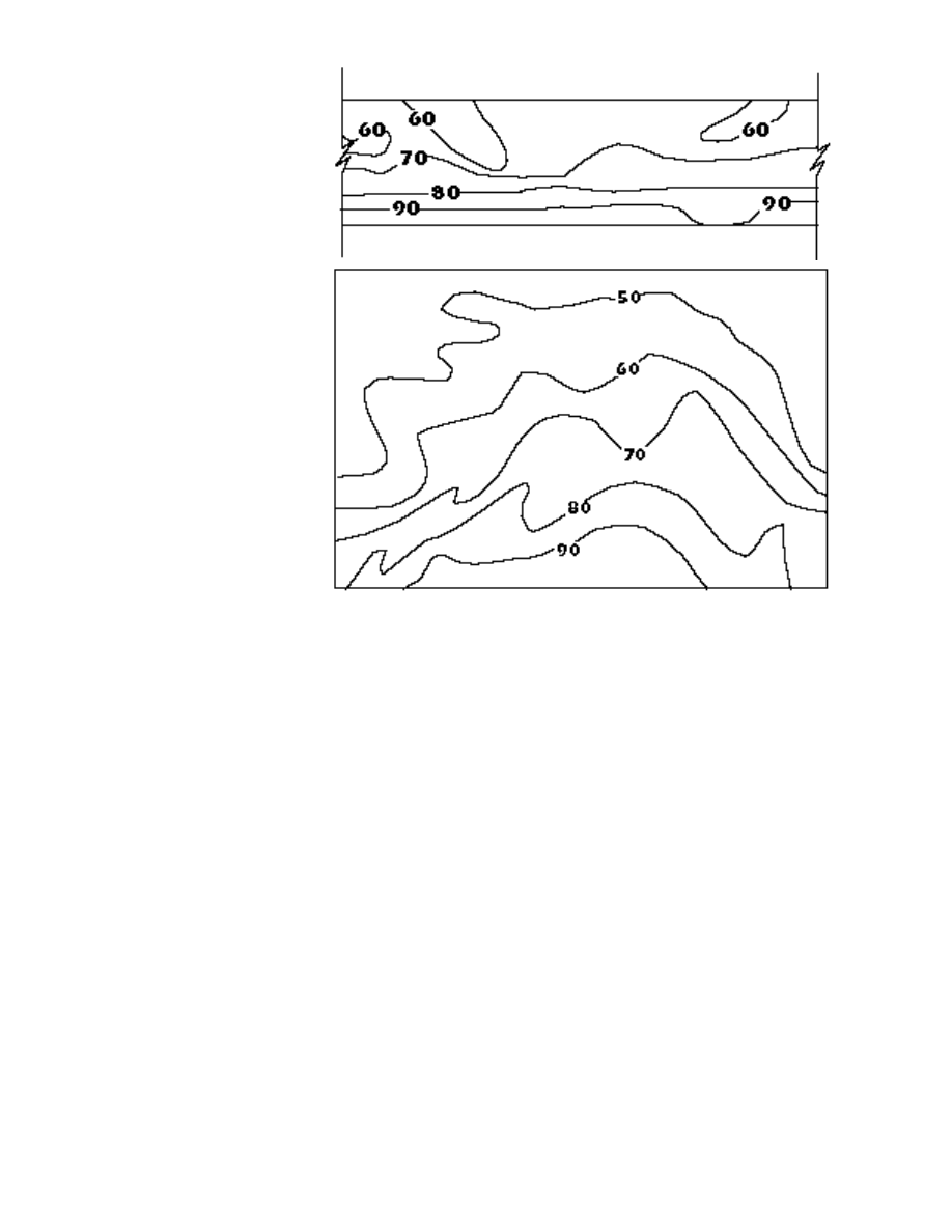
Figure 3.
Typical relative percentage strength contours for a beam (top) and for a wall (bottom).
PUBLICATION #J950134
Copyright © 1995, The Aberdeen Group
All rights reserved
Wyszukiwarka
Podobne podstrony:
making tea in place experiences of women engaged in a japanese tea ceremony
Johnson Summary brief shades of embeddedness Tie strengh and obligations in direct selling parties
Natural variations detected in the isotopic composition of copper possible applications to archeolo
Cleaning In Place Technology(1)
Clean In Place Review
Cleaning In Place Systems
Evaluation of in vitro anticancer activities
Top of Volcano Blown of in Blast!
Cleaning in Place
Cleaning In Place Technology(1)
Clean In Place Review
Laurence M Janifer Agent in Place
variation of 7979 for claire opis
Rohloff 2004 Chemotypical variation of tansy
tekst Selena Gomez Wizards Of Waverly Place Thame po polsku
Prepositions of time, place and transport
więcej podobnych podstron