Use and Care
Instructions
for your new
T1 Turgo
Micro-hydroelectric Generator
Models: MHG-T1
Asian Phoenix Resources Ltd., Canada
READ THIS FIRST
This manual contains important information concerning your new PowerPal T1 Turgo
micro-hydroelectric generator. It covers Model MHG-T1. You should read this
manual carefully before installing PowerPal or allow a trained technician from your
local PowerPal Service Center to install it for you.
Your PowerPal generator is designed to be simple to operate and easy to maintain. If
used in accordance with these instructions your PowerPal will give you many years of
service. PowerPal is also designed with safety in mind, but any electric device can be
dangerous if not used correctly. At several points in this manual, instructions
requiring special attention that must be followed are shown as:
Warning symbol - beware of hazards or unsafe practices that may cause
injury or death.
Caution symbol – beware of hazards or unsafe practices that may damage the
product.
SAFETY FIRST
While electricity improves your life, it can also be dangerous if simple
precautions are not followed:
• Never allow electrical contacts to become wet. Beware of electrocution.
• Never attempt to cut electrical wires or open appliances for repair if the generator
is working. Unplug the main cable first.
• Inform children of the dangers of electrocution. Never allow them to play with
electrical connections.
• Keep fingers away from the moving turbine runner. If partly blocked with debris,
stop the water flow before cleaning.
• If you have any questions about safety, please ask your PowerPal Service Center.
• Product must be earth bonded (grounded).
OPERATING CAUTIONS
Your PowerPal generator is designed for simple operation and low
maintenance. However, the following operating cautions must be followed to
ensure a long life for PowerPal:
• Under conditions of higher water heads than given for each model in this manual,
PowerPal is able to generate higher power outputs than rated. This can also occur
if the intake pipe diameter exceeds the recommended diameter. If maximum
power consumption listed in this manual is exceeded then the PowerPal generator
may be irrepairably damaged and require total rewiring. See the section on
‘Technical Specifications’.
•
Do not forget to grease the bearings at the recommended times. Failure to do this
will result in excessive wear on the bearings and shorten their life.
•
Always ensure that the Electronic Load Controller is set at approximately 220V.
Otherwise, the life of lights and appliances may be reduced.
PowerPal™ T1 Turgo 2

POWERPAL COMPONENTS
Inside your PowerPal box you will find:
• 1 x generator-turbine assembly
• 1 x penstock adaptor flange, internal diameter 150mm
• 1 x rubber gasket
• 4 x M12 foundation nuts and bolts
• 1 x control panel including electronic load controller
• 1 x ballast load
• 1 x Guarantee Card
• 1 x this instruction manual.
Please advise immediately if any parts are missing. Complete your Guarantee Card
and have it signed by your PowerPal dealer.
The PowerPal system consists of two major components – a hydroelectric generator
and an electronic load controller. Other components are necessary and these can be
purchased locally. The penstock (intake pipe) should be made from either steel or
schedule 40 PVC. Your PowerPal dealer can advise you about this.
Therefore, other parts which are not included in the box but which are required to
make PowerPal work are:
• a length of steel or PVC pipe with internal diameter 110mm. Pipe length will
affect your power output (see page 5).
• electrical wire from generator to house. See the section on ‘Technical
Specifications’ for the correct wire size.
• household wiring.
These are available from your dealer or local electrical store.
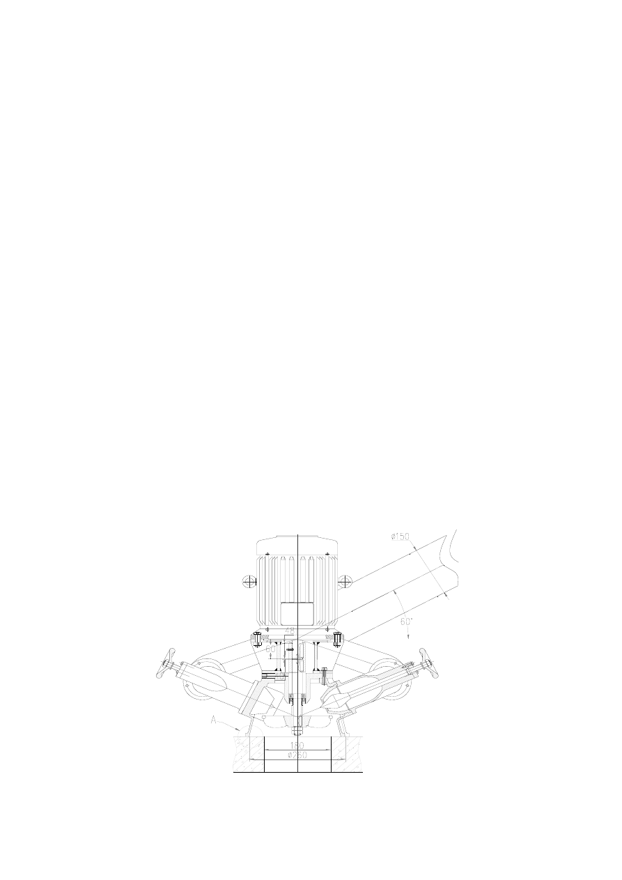
SYSTEM DIAGRAM
The following diagram shows how the non-electrical components fit together. Further
reading of this manual will provide the necessary explanations. The components are:
PowerPal™ T1 Turgo 3
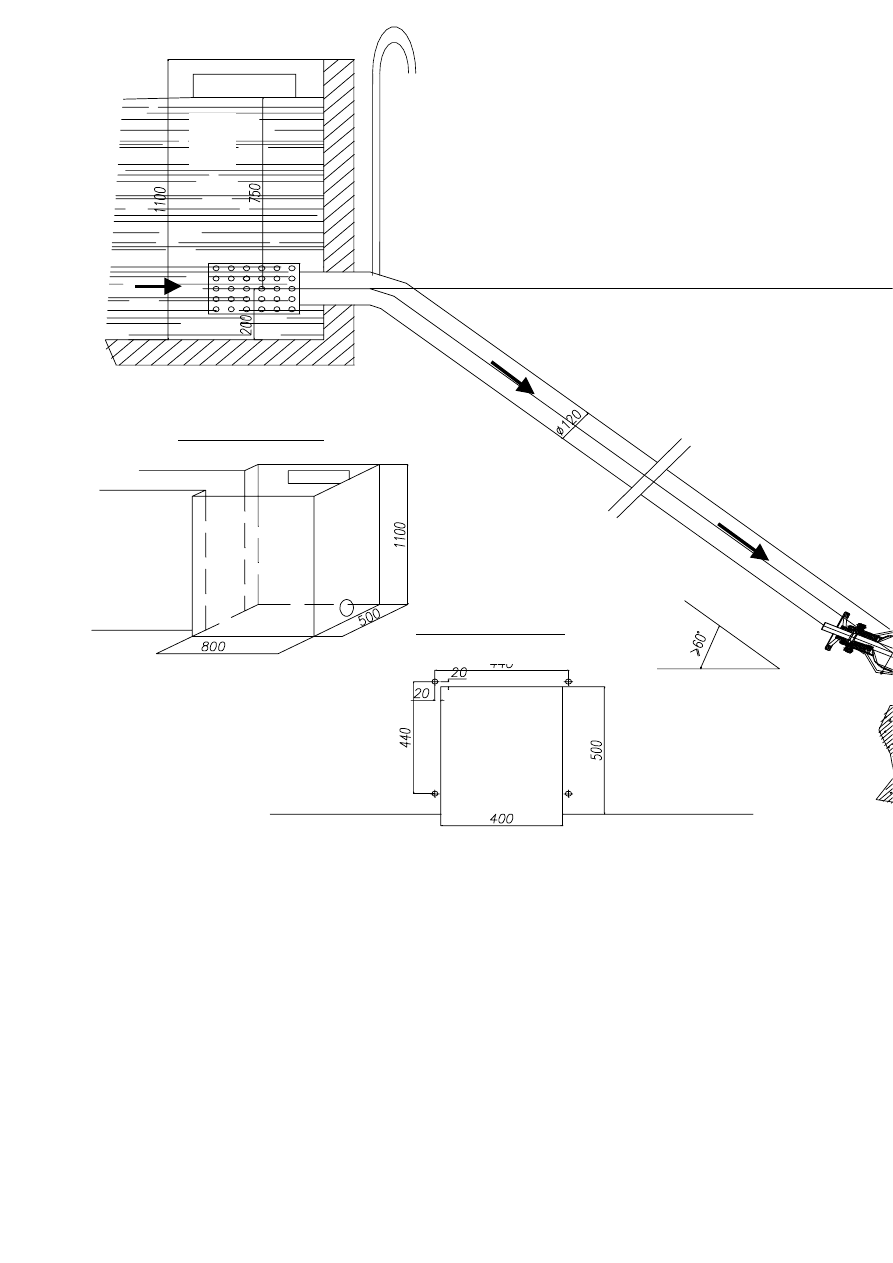
Turbine stand layout
445
Forebay dimensions
D
C
B
A
A.
B.
C.
D.
E.
F.
G.
Di
SELECTING A SITE
PowerPal is designed for use in a wide range of locations. There are two critical
factors that influence power output – head and flow. Head is the vertical distance
between the turbine and the water source (forebay), measured in meters. Flow is the
amount of water that passes through the turbine at any instant, measured in litres per
second (l/sec). The following table shows the various combinations of head and flow
to achieve certain maximum power outputs for each model:
MHG-T1
Gross head H 8 m
9m
10m 11m
Water flow Q 21 l/sec 22 l/sec 23 l/sec 23 l/sec
Turbine output 880W
1.04kW 1.2kW
1.33kW
Gen.
output
660W 788W 900W 1kW
For example, if your site has available 11 meters of head and a water flow of 23 litres
per second then a PowerPal MHG-T1 will produce up to 1kW of electricity.
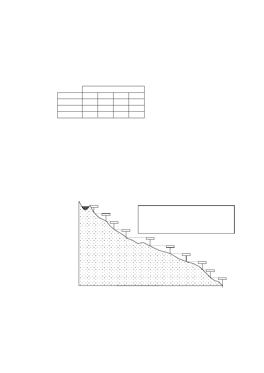
Measuring Gross Head
The gross head is the vertical height from where the water flow enters the penstock
down to the level of the turbine. It is shown in the System Diagram. To measure this,
use a tape measure and a clinometer or spirit level etc. A less accurate but useful
alternative is to make your own level from a transparent tube half-filled with water.
Attach this to the top of a 1m long stick and then point this horizontally at a point
further up the slope as though it were a spirit level. By going to that point and
repeating the process the total gross head can be measured – see the drawing below.
ter
Measuring Gross Head:
Walk up the slope from where you wish to place
the turbine to where the water source is. Or, do
the reverse: walk down the slope from the wa
source to locate the best site for the turbine.
10m
9
8
7
6
5
4
3
2
1
0m
Another method is to use an accurate pressure gauge and a length of hose. Run a
water-filled hose from the forebay to the turbine site and attach the pressure gauge to
the bottom end. The pressure gauge shows 1.422 psi / meter of head e.g. 11.4 psi for a
head of 8m to 24.2 psi for a head of 17m.
This head should be between 8 and 11 meters for the MHG-T1 model. If it is smaller
then the power output will be reduced. If it is larger then your power output will be
PowerPal™ T1 Turgo 5
increased. While increased power output appears desirable, if the head is too large
then the rotor will turn too fast and reduce the life of the bearings unless the spear
valve is used to reduce flow.
Do not attempt to exceed the recommended head height.
Measuring Flow
The best way to measure the water flow is to take a piece of pipe the same diameter as
the penstock, insert it in the stream or dam where the flow is expected to come from,
and measure the flow from there.
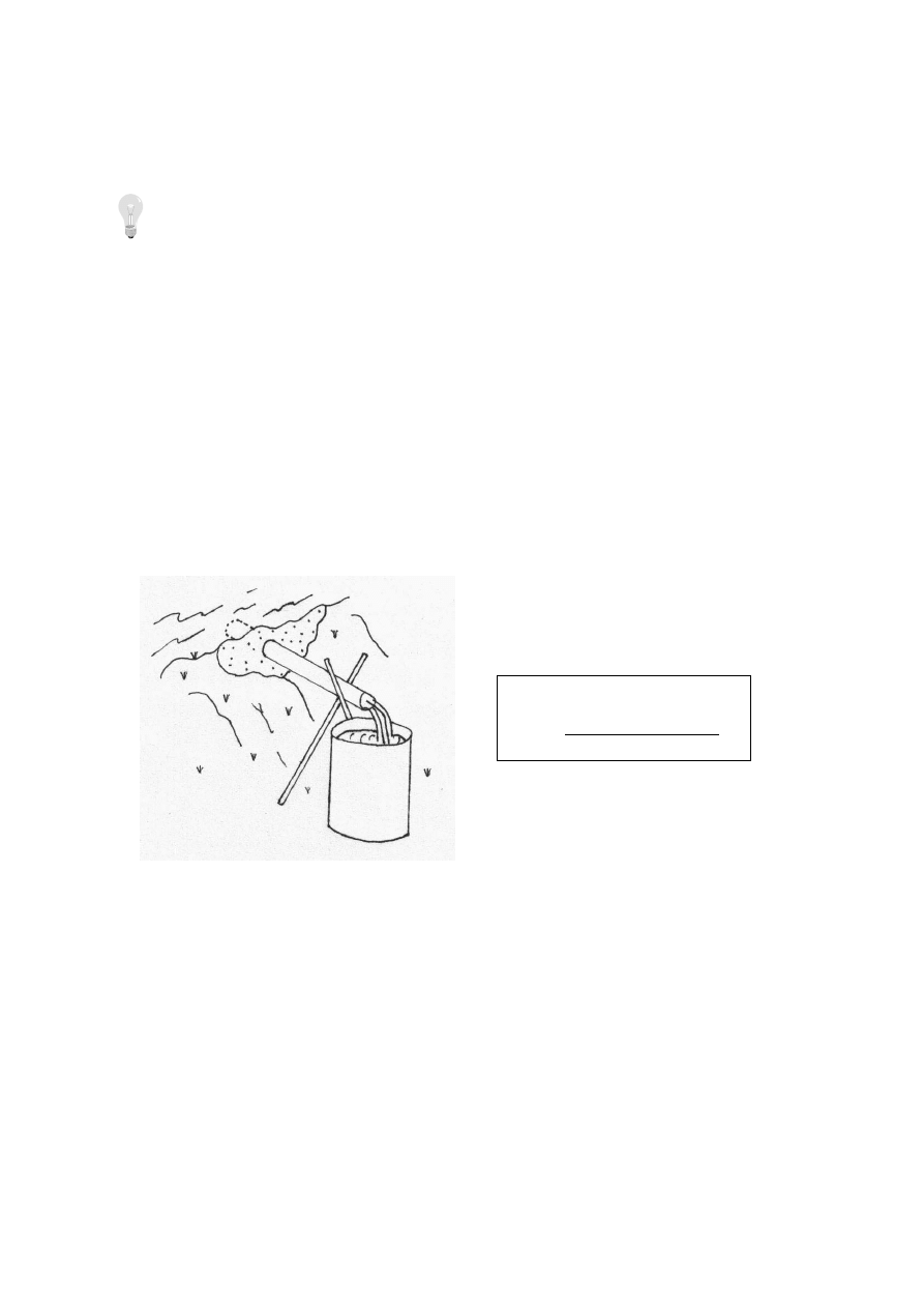
In the diagram below, a short length of pipe (less than 1 meter) is buried into the side
of a small ‘dam’ using mud or improvised sandbags. The top end of the pipe is
completely submerged and part of the normal stream flow is diverted through the
pipe. When this is flowing smoothly, a bucket of known volume is quickly placed to
collect this flow and the time it takes to fill the bucket is recorded. The ideal bucket
size would be 100 or 200 litres (half or a whole empty oil drum), but smaller buckets
will work. Divide the volume of the bucket (in litres) by the time it takes to fill the
bucket (in seconds) to get the approximate flow rate in litres per second.
Measuring Flow:
Flow = volume of bucket (litres)
time to fill bucket (seconds)
SITE PREPARATION
Once the correct head and flow have been located then the length and position of the
penstock can be determined. While vertical head is important, the horizontal slope and
penstock length may vary although penstock inclination should be >60
°.
The penstock should be made of PVC or steel with internal diameter of 150mm and
thickness of at least 3mm. A larger diameter pipe can be used however this is
generally more costly. A gate valve is a good idea and may be installed at the high-
pressure end of the penstock for closing whenever servicing the turbine.
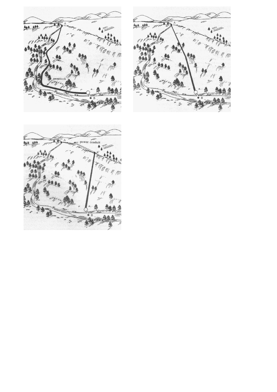
A good way to reduce penstock length is shown in the following diagram.
PowerPal™ T1 Turgo 6
C
A
B
The penstock is shown by the black line
A-B. In the first diagram (A) the penstock
follows the stream. This may lead to
unnecessary length and cost. In diagram
B, the most direct route is selected to
reduce length and cost. Diagram C shows
the best alternative where a side channel
or ‘power conduit’ is cut into the side of
the hill. This carries the water to a point
as close to above the turbine as possible
and best reduces the length of penstock
required.
The power conduit roughly follows the
hill’s contour and need only be a simple
ditch say 30cm x 30cm in section.
When installing the penstock, try to keep it as straight as possible and avoid sharp
turns or angles. To do this, part of the hillslope may need excavating while in other
places the penstock may need supporting with poles etc. Steeper terrain has advan-
tages over more gentle terrain as cost is reduced by the use of a shorter penstock.
The forebay, or water holding tank at the top of the penstock is designed to contain a
water volume of at least 2.5x the volume of water in the penstock i.e. 440 litres.
Dimensions of the ideal design are shown in the system diagram although the main
point is to ensure that the forebay won’t become empty.
The top of the penstock is typically placed not at the bottom but some way up the
forebay wall so that the bottom of the forebay acts as a sink for rotting leaf litter,
deposited sand and mud etc. This sink may need periodic cleaning out. Another good
idea is to cover the end of the penstock with a piece of wire mesh (debris screen) to
keep leaves etc. from flowing in and clogging the turbine. See Appendix A for the
ideal forebay design.
SYSTEM INSTALLATION
PowerPal™ T1 Turgo 7

Mechanical Aspects
After locating a suitable site and completing the civil works, your PowerPal is ready
for installation. To do this:
1. Bolt the turbine to a turbine stand or base which allows at least 300mm clearance
between the turbine and the ground. This clearance is required to prevent
splashback that will disrupt turbine performance. The turbine stand should be
made from concrete with the four M12 foundation bolts embedded. Bolt spacing
is shown in the system diagram but check this against the turbine casing.
2. Turn the handle of the spear valve until the valve is fully closed.
Always turn the handle slowly and smoothly.
3. Affix an elbow bend into the forebay wall. This should be fitted with an
atmospheric vent (hollow bent pipe), which allows air to escape from the
penstock. The upper opening of the atmospheric vent should be higher than the
water level in the forebay. Divert water away from the forebay or else block the
top of the penstock pipe during the installation procedure.
4. Affix a suitable elbow bend to the turbine to allow its connection to the penstock.
A gate valve may also be installed at this point, if required.
5. Start installing the penstock. Assembly can begin from either direction but it is
usually easier to begin uphill – the turbine is much easier to move around than the
forebay is. The penstock should be well secured i.e. strongly supported with
periodic anchors or buried at regular intervals to support its weight when full –
this is particularly important at any bends and at the bottom of the penstock so that
PowerPal cannot be knocked over. At least two people should handle the
penstock, one uphill and one downhill, until it is fitted into both elbow bends.
Electrical Aspects
The generator is a double-winding, capacitive, modified 3-phase induction motor
which has zero-load voltage built up by residual magnetism. Its direction of rotation is
clockwise when viewed from the generator end. It has been modified to produce
single-phase electrical power. This conversion takes place in the control box. Load is
controlled by an electronic load controller (ELC) which is installed as part of the
control box. The ELC is designed to maintain constant voltage by keeping a constant
power on the generator output. To do this, the ELC switches any power not being
used by the consumer to a ballast load (supplied) where the surplus energy is burnt off
as heat. The ELC is wired in parallel with the generator output so that it can’t be
inadvertantly switched out of the circuit. The system is connected as follows:
PowerPal™ T1 Turgo 8
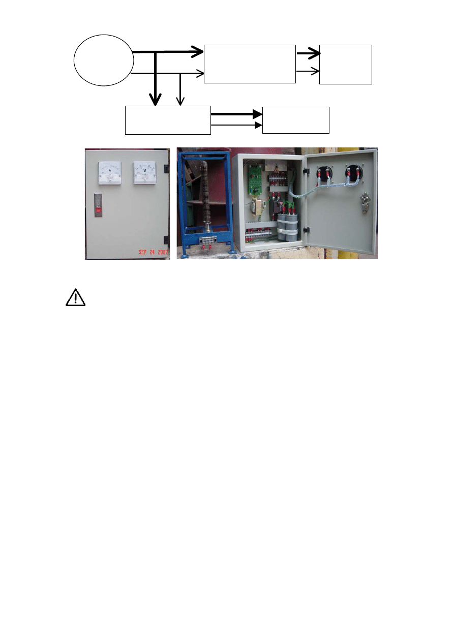
220VAC
house supply
Ballast load
Electronic Load
Controller - ELC
Main network or house
distribution board
hydro
turbine
To connect the electrical components, please follow these steps:
The electrics should be installed by persons competent in mains voltage
wiring. This system operates on a switched neutral basis. Neutral and phase
connections to the load elements should be treated as live at all times!
1. Install the control box (A) in a convenient location that is protected from rain and
sun. This may be either in a powerhouse along with the turbine or else in a house
at the user’s end.
2. Earth-bond (ground) PowerPal. Do this by attaching one end of a suitable length
of wire to PowerPal and the other end to a metal object or metal stake in the
ground nearby PowerPal. Although the risk of electric shock is already low, this
earth-bonding is still best practice.
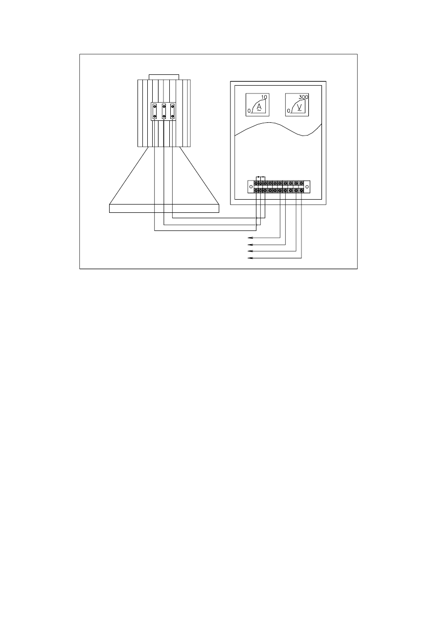
3. Connect the generator to the control box (B). All wiring from the generator to the
control box, from the control box to the user load and from the control box to the
ballast load should be done using insulated multistrand copper wire, the size of
which is given in the Technical Specifications part of this manual. The following
wiring diagram applies:
PowerPal™ T1 Turgo 9
BL1
BL2
(AIR LOAD)
BALLAST LOAD
L2
L1
TO USER
220VAC
40mF
80mF
TERMINAL
5
6
7
8
9
10
1 2
3
4
LC
LB
LA
LA
BOX CONTROL
LB LC
GENERATOR CONTROL
INDUCTION
A1 N1
A3 N3
4. Connect the user load cables L1 and L2 between the control box and the house.
5. Connect the ballast load (C) to the control box and user load cable. The ballast
load is rated 10-15% (maximum) higher than the rated power output of the
generator e.g. 1.5kW for model MHG-T1. As such, it will become hot, up to
100
°C. To prevent injury and the risk of fire, the ballast load must be installed in a
safe place and preferably in an additional enclosure.
6. Close the generator terminal box and the control box door. The system is now
ready for its first operation.
OPERATION
1. Check that the power conduit and forebay are free of debris.
2. Ensure that the turbine is shut down and that all supply lines are electrically dead.
The switch on the door of the control box must be in the ‘off’ position.
3. Fill the forebay and allow the water to flow gradually into the penstock. The spear
valve should be fully closed, then backed out one full turn at this stage. The
turbine runner will rotate and spent water will escape through the floor of the
platform.
4. As the water flow starts to create electric power, the voltage will rise until the
voltmeter on the control box reads 230V. Once this occurs, turn the control box
switch to the ‘on’ position and then adjust the water flow with the spear valve so
that the voltage stays at 230V. The voltage will then fall down after some seconds.
PowerPal™ T1 Turgo 10

When it happens, openning spare valve to adjust water through turbine, look at
voltmeter on the panel is increasing. Turn this valve untill its value is 220V then
stop.
5. Operate like this for 15 minutes while observing any unusual noise, excessive
temperature or other problems and if OK then switch on the power to the user. Up
till now the ballast load has been receiving all the power and should be hot, but
once switching on the user load the power to the ballast load will fall.
6. The voltage should remain stable as loads are switched on or off. If the voltage
falls below 220V then check the water flow conditions. The voltage may need to
be checked and adjusted if the water flow rate changes e.g. a prolonged dry period
may gradually reduce it.
Do not allow electrical contacts to become wet. Use dry hands. Beware of
electrocution.
Avoid plugging appliances directly into PowerPal without using the load
controller. Incorrect voltage may result, which can damage your appliance.
7. Whenever shutting down the system, first close the valve to reduce the flow rate
and once the voltmeter shows 100V, switch the control box to the ‘off’ position.
Then close the valve fully to stop the system.
CARE AND MAINTENANCE
General care for your PowerPal will enhance its life. Following the instructions in this
manual is important.
Try to install PowerPal in a place that is unlikely to be flooded. A simple shelter with
a roof will also help protect the generator from rain or else a small shed can be built
and locked if security is an issue. If the inside of the generator assembly does become
wet it will require drying. No permanent damage will result, but check the bearings to
see if they have collected water. Do not try to dry it near a fire. Before using again,
make sure that the power socket is also dry. Condensation inside the generator is
normal in tropical areas and will not effect the performance of PowerPal.
Greasing the Bearings
PowerPal has three bearings, two in the generator and one in the turbine. The
generator bearings are maintenance-free while the turbine bearing has been greased in
the factory ready for use but requires re-greasing every 3 months of continuous use.
To do this, clean the nipple on the bearing casing and apply extra grease with a grease
gun. There is no need to stop the turbine to grease this bearing.
PowerPal™ T1 Turgo 11
Failure to grease the bearings on
time will shorten their life and
require their replacement. The
increased friction will also reduce
power output. Always clean the
nipple before greasing.
Changing the Bearings and Seal
Apart from greasing the bearing, there are only two tasks that must be completed at
regular intervals. These are the changing of the lower generator bearing & turbine
bearing and the lower bearing seal every two years. See the section on Technical
Specifications at the end of this manual for part numbers. These are commonly
available in most countries but if in doubt contact your dealer. To replace the bearings
and seal, follow these steps:
1. Shut down the system and disconnect the power cable at the generator.
2. Drain the forebay so that the water flow stops. Do not simply block the top of the
penstock. Leave the spear valve open.
3. Wait till the penstock is drained i.e. little or no water flows out of the turbine.
4. Disconnect the turbine from the penstock
5. Unbolt the turbine and remove from the turbine stand.
6. Turn PowerPal on its side (photo A).
7. Unbolt and remove the runner (photo B).
8. Unbolt and remove the generator from the turbine casing (photo C).
9. Unbolt and remove the turbine bearing casing (photo D).
10. The turbine bearing is now visible (photo E) above the seal. Remove these using a
bearing removal tool. The seal is a black rubber ring (center of photo F) and is
there to prevent water entering the generator.
11. Before replacing the bearing ensure that the casing is clean and greased (photo F).
12. To replace the lower generator bearing, disconnect the bearing housing and use a
bearing removal tool.
13. When reassembling, make sure that all parts are correctly in place and that all
bolts are tightened.
14. After PowerPal has been securely reconnected to the turbine stand and penstock
adaptor flange the forebay is refilled and normal water flow is allowed to
continue. Wait until this occurs before reconnecting the cable and appliances.
PowerPal™ T1 Turgo 12
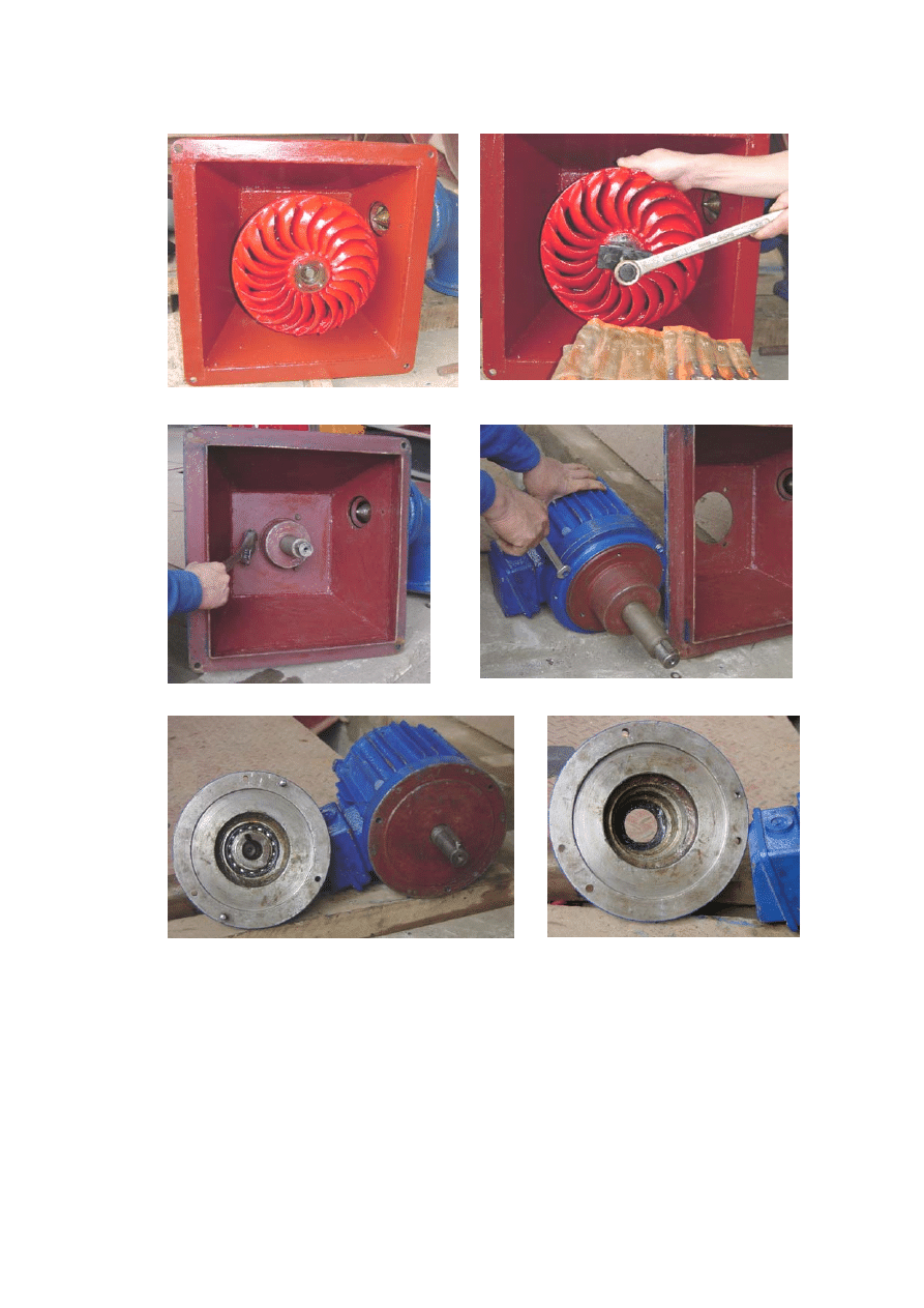
E F
C D
A B
TROUBLESHOOTING
If any problems are encountered, check this section before contacting your Service
Center.
1. Head and flow conditions appear to be OK, but PowerPal will not work.
It is likely that the system has been installed incorrectly. Check this by following the
steps once more.
PowerPal™ T1 Turgo 13

2. PowerPal has provided electricity for a while and suddenly the electricity stops.
If this instruction manual is not followed and power consumption is too high, or if
there is a short circuit in an appliance the circuit breaker in the electronic load
controller will trip. This will stop the electric current. If this occurs, check for possible
causes and rectify. Reset the switch on the circuit breaker to the ‘on’ position.
3. Voltage is 220V under zero-load conditions but falls when a load is applied.
Either a capacitor in the control box has been damaged or excessive load has been
applied. Reduce the load consumption to see if voltage stabilizes and if not have the
control box examined by a competent electrician.
4. Testing in the stream showed that PowerPal was capable of producing the rated
output power (1000W or 2000W, depending on model). However, after running
the electrical cable to the house this output power was found to be less.
Due to resistance from the cable, long cable runs will result in a small loss of output
power. Power loss over a 100m cable run is approximately 10W. For log wire runs it
is possible to install a 4.75~10µf capacitor at the load end or otherwise to increase the
cable diameter.
5. Power output has been falling recently.
Falling output suggests that the turbine is rotating more slowly than usual. Make sure
that the enough water is entering the forebay and ensure that the source river is
adequate for the flow being consumed. Otherwise, check the forebay and penstock
filter and clean if necessary. There may be soft organic debris such as rotten leaves
restricting the spear valve. Try running the valve completely closed and completely
open one or two cycles. This may clear the valve of any foreign material and open it
up to full power again. If that happens, then you should go to the forebay and be sure
that it is clean, and eliminate the cause that allowed the foreign material into the
pipeline in the first place. You can also check that the runner is free of leaves and
other debris and that the turbine bearing has enough grease. Under certain conditions
the generator may lose magnetism and result in loss of power. Its main winding may
be re-magnetized by applying a 3V DC power source and energizing for approx-
imately 30 seconds.
6. On starting, the control panel shows 220-240 volts and zero amps. The circuit
breaker has been turned “on” with the user load “off.” No power goes to the
ballast resistor.
Check the voltage at the right side of the transformer, it should be 220-240 volts.
Check voltage at the left side of the transformer, it should be 18-25 volts. If not, the
transformer is faulty. If yes, check the voltage at the terminals at the top of the circuit
board. This should be 18-25 volts. Check the voltage at the terminals at the bottom of
the circuit board. This should be AC, low voltage. If there is 18-25 volts at the top of
the circuit board and no voltage at the bottom of the circuit board, then something in
PowerPal™ T1 Turgo 14

the circuit board is faulty. If that is the case, try adjusting the potentiometer as
follows:
a) Start the generator and adjust the spear valve to obtain 220-240 volts, 0 amps at the
panel. [Do not turn the circuit breaker on].
b) Adjust the potentiometer on the circuit board very slowly to the left. When you
detect a small decrease in voltage, stop. Turn on the circuit breaker and increase water
to increase power to the unit. Increase power until a load of 2kW is indicated (P =VI).
c) If adjusting the potentiometer does not correct the problem, then contact PowerPal.
The problem is probably with the potentiometer.
TECHNICAL SPECIFICATIONS
MHG-T1
1 Rated
power
output
1000W
2
Maximum allowable load
1200W
3 Intended
voltage
220V~
4
Frequency at rated power output
50 Hz
5
Frequency at runaway speed
70 Hz
6 Runaway
speed
1500rpm
7 Height
600mm
8 Weight
48kg
9
Turbine runner type
Turgo
10 Runner
diameter
270mm
11 Number
of
buckets
20
12 Number
of
nozzles
1
13
Generator
3- phase
14
Generator insulation
Class B
15 Protection
grade
IP44
16
Load controller circuit breaker
10A
17
Turbine bearing size
SKF 1204
18 Seal
size
42x62x10mm
19 Recommended
cable
2.5mm2
20 Operating
temperature
5 to 50
° C
21
Operating humidity
0 to 90%
Notes:
1,2.
Rated power output is the manufacturer’s specified output for the given head
and flow conditions. A higher output is possible if the head is greater or the flow is
faster than recommended. If the maximum allowable load is exceeded then permanent
damage to the stator may occur.
3.
Is approximately 220V when the ELC is used.
5,6.
Runaway speed is the speed of the rotor if no load is applied. This speed is
reduced under load.
18.
We recommend SKF brand or similar high quality bearings.
Also, the diagrams and much useful information on pages 7 and 16 are taken from
Micro-hydropower Sourcebook – A Practical Guide to Design and Implementation in
Developing Countries. NRECA, 1986.
PowerPal™ T1 Turgo 15
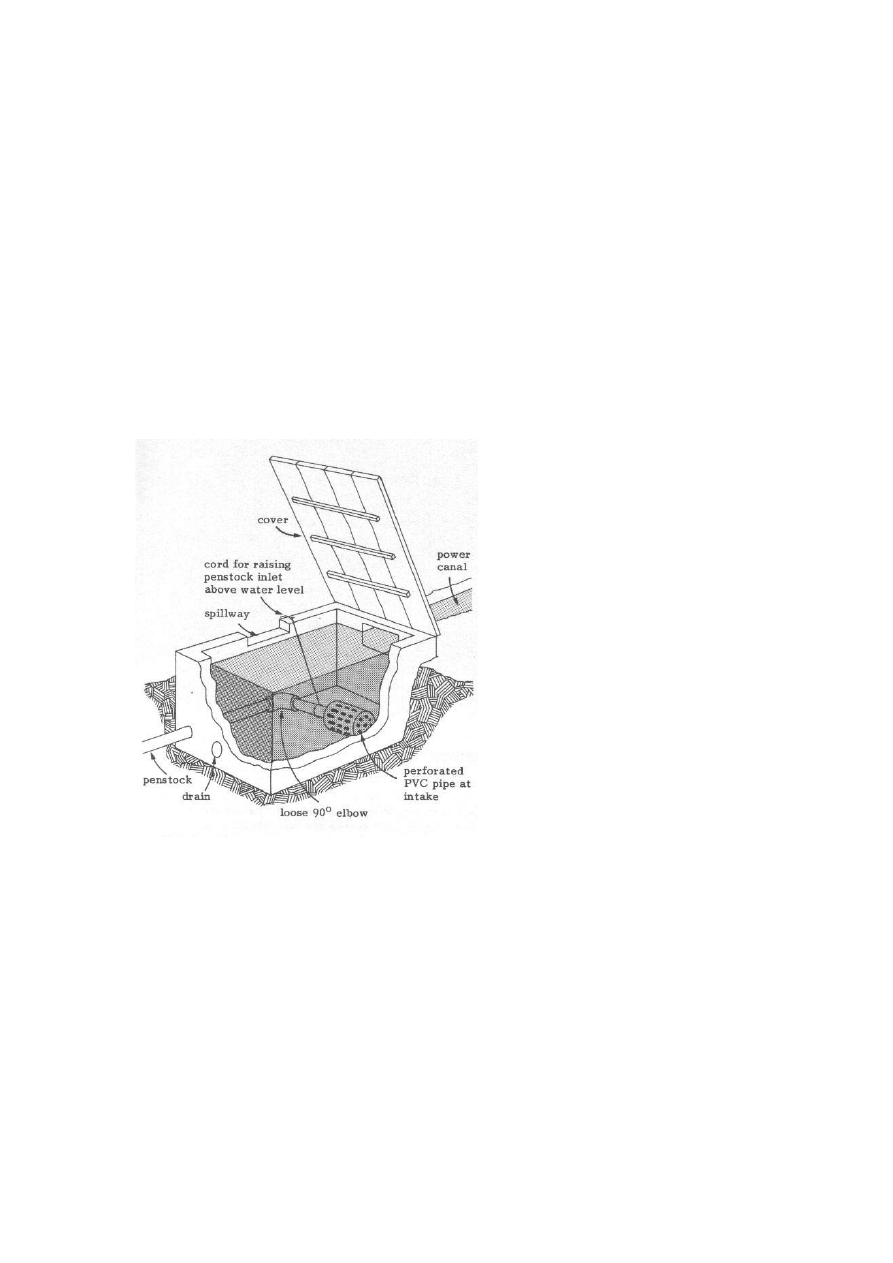
APPENDIX A – FOREBAY DESIGN
The instructions given on page 7 of this manual to design the forebay are adequate for
most cases. The most important aspects of forebay design are:
1) To allow a continual flow of water to the penstock so that the turbine keeps
functioning.
2) To have sufficient safeguards to prevent sand, vegetation and other debris
from entering the penstock which could cause blockages and disrupt the
turbine. This includes a safety aspect to keep away children and animals that
could possibly be injured by the suction of water entering the penstock.
3) To have an easy way to stop the water flow when changing the bearings etc.
The following diagram shows a simple forebay design that may be used to achieve all
the above goals.
the penstock. For example, if using the recommended 110mm diameter penstock then
95 x 1cm diameter holes should be drilled into the inlet screen (or 380 x 0.5cm
diameter holes etc.). The length of the inlet screen doesn’t matter, so long as the
minimum number of holes can be added. Bore casing with narrow, long slits is ideal.
Here, the forebay is made of a
waterproofed box situated
between the power canal (power
conduit) and the penstock. A
loosely fitting elbow is inserted
between the penstock inlet and
the main penstock pipe. Flow to
the penstock is cut off by pulling
the cord so that the inlet is out of
the water. The plugged drain is
used to periodically empty out
sand and leaves or else this can be
shoveled out. The perforated pipe
end further reduces litter intake.
Here the number of holes is
important so that flow is not
obstructed. To allow optimal,
uninterrupted flow, the open part
of the inlet screen should be at
least four times the open area of
The cover will help keep the forebay clean and may be locked to keep away children.
PowerPal™ T1 Turgo 16
Wyszukiwarka
Podobne podstrony:
Instructions for your download
BRAUN recipes for your baby and toddler
42 577 595 Optimized Heat Treatment and Nitriding Parametres for a New Hot Work Steel
Dungeons and Dragons suplement New and Converted Races for D&D 3 5 Accessory
SAF HOLLAND Instructions for Use Universal Disc Brake To
Kalmus, Realo, Siibak (2011) Motives for internet use and their relationships with personality trait
Instructions for the hydraulic system and the flue pipes BRACKET INSTRUCTIONS
Creation of Financial Instruments for Financing Investments in Culture Heritage and Cultural and Cre
Instructions for manually installing FreeSpace Open and mods (Windows)
Suture Materials and Suture Selection for Use in Exotic Pet Surgical
Instructions for manually installing FreeSpace Open and mods (Mac OS X)
Grepstad, Jon Building a Large Format Camera Plans and Instructions for Building a 4 X 5 Monorail
Affirmations Tools For Your Mind, Soul and Spirit By Linda Ann Stewart
How and When to Be Your Own Doctor
Basel II and Regulatory Framework for Islamic Banks
7 3 1 2 Packet Tracer Simulation Exploration of TCP and UDP Instructions
więcej podobnych podstron