
Building a Large Format Camera
Jon Grepstad
Second, revised edition
Oslo 2000

2
3
2000 Jon Grepstad
Hertug Skules gate 12
0652 Oslo, Norway
Second revised edition
First edition: 1996
E-mail: gjon@online.no
World Wide Web: http://home.online.no/~gjon/
Printed in Norway. All rights reserved.
No part of this publication may be reproduced, stored in a retrieval
system, or transmitted, in any form or by any means, electronic,
mechanical, photocopying, or otherwise, without the prior
permission of the author.
ISBN 82-993938-1-7

4

5
Preface
In the spring of 1991 I came across an article on
building your own large format camera. The article,
published in 1988 in a Swedish photo magazine, was
based on the advice and experience of a professional
Swedish camera builder, Kurt Lundell.
In the summer and autumn of 1991 I built my first
monorail camera of oak, brass and aluminum. I was
inspired by Kurt Lundell’s article but collected
information from a large number of sources. I read
articles in photo magazines, bought books about large
format cameras, borrowed books from libraries about
classic cameras, and studied specifications and pictures
in sales brochures for most brands of current view
cameras. On the basis of my reading I made sketches,
then scale drawings on graph paper, and then went to
the local lumber-yard to look for suitable woods. I
experimented with various solutions for details of the
camera and made numerous visits to hardware stores to
find the right types of screws or potential metal parts.
During the construction process a number of drawings
were revised and changed.
I have written this manual because building a large
format camera is a greatly rewarding experience which
I want to share with others. During the past six years I
have spent considerable time on the Internet and have
noticed with increasing frequency questions about
sources and plans for building your own view camera.
A few books or pamphlets are around, in English or
German. Although they are useful as sources of
inspiration or guidance, I feel they all have their
shortcomings. There are several details I think should
be improved. I also think a view camera should not
only be a good tool for making images, but it should
also be a beautiful object in itself.
This manual provides instructions and plans for a 4 x 5
in. monorail camera built of hardwood, and with some
brass and aluminum parts. The focusing system is
based on friction focusing. The lens, of course, will
have to be bought. It is also suggested that you buy the
bellows and the ground glass. However, my book
provides references and sources for those who wish to
make their own bellows, as well as instructions for
grinding your own glass. Building a Large Format
Camera is aimed at woodworkers with average skills
and experience. The basic principles of a camera are
simple. Building a camera requires patience and
accuracy, but is far easier than making, for instance, a
stringed instrument. Building a camera may take
50–80 hours. Part of the pleasure is pondering over
details and alternative designs.
My design is largely modular. Parts may be replaced
with other parts of different designs to meet your needs
and preferences. The front and rear standards, for
instance, may be customized depending on your needs
for camera movements. You may construct an extra
frame for attaching a second bellows for extreme close-
ups or long telephoto lenses. The 4 x 5 spring back may
be replaced with a step-up adapter for the 5 x 7 image

6
format. A lamp housing and a negative carrier may be
added along with a table-top optical bench to transform
the camera into a horizontal enlarger, and so forth.
These plans and instructions are for a 4 x 5 camera. But
the plans may be scaled up for a 5 x 7 or an 8 x 10
camera. Crucial information on the position of the
ground glass for these formats is found in chapter 4.3.
Advice for scaling up is given in chapter 6.5.
If you have questions about the design, please feel free
to contact me. To the extent that my time permits it I
will try to reply. If possible, use e-mail. If you are
using postal mail, please enclose a self-addressed
envelope and international reply coupons to cover
postage. Also, if there are things in this guide you feel
should be improved, please let me know! I would like
Building a Large Format Camera to be an inspiring
and practical guide for woodworkers and
photographers who want to build their own camera.
English is not my native language. I wish to thank my
dear friend Yvette, who read an early draft of this
manual and commented on the language. I am solely
responsible for the final text.
The first edition of this book appeared in April 1996. In
the second edition I have added more photographs of
the camera and have inserted a number of drawings in
the text. I have included instructions for a more
sophisticated design of the ground glass frame. The
bibliography and other references have been updated.
In particular more references to sources on bellows-
making have been included.
Oslo, Norway, 1 January 2000
Jon Grepstad

7
Contents
1 Large Format Cameras
1.1 Benefits of Large Format Cameras
1.2 Drawbacks of Large Format Cameras
2 Designing and Building a Large Format Camera
2.1 List of Materials
3 The Basic Outline
4 The Construction Process
4.1 The Front and Rear Frames
4.2 The Lens Board
4.3 The Spring Back
4.4 Lock Mechanism for the Spring Back
4.5 Lock Mechanism for the Lens Board
4.6
Standards
4.7 The Optical Bench
4.8 Mounting the Lens on the Lens board
4.9 Attaching the Bellows
4.10 Finishing the Wood
5 Testing the Camera
5.1 Testing for Light Leaks
5.2 Testing Focusing
6 Appendices
6.1 Making a Ground Glass
6.2 Making a Bellows
6.3 Making a Camera Case
6.4 Step-up Adapter for the 5 x 7 Format
6.5 Scaling the Plans up for an 8 x 10 Camera
7 Notes on Lenses for Beginners
7.1 Covering Power of Lenses
7.2 Normal, Wide-Angle and Telephoto Lenses
7.3 Buying a Lens
8 Operating the Camera
8.1 Loading Film Holders
8.2 Taking Pictures
8.3 Exposure and Bellows Factor
8.4 Depth of Field, Hyperfocal Distance, Circle
of Confusion and Depth of Focus
8.5 Camera Movements
8.6 Developing Sheet Film
Addendum: A more elaborate ground glass frame
Pictures of the Camera
Literature and References
Addresses (US, UK and Scandinavian)
Conversion Table
Figures (Drawings)

8

9
1 Large Format Cameras
Large format cameras are cameras that take film
generally in sizes 4 x 5 in., 5 x 7 in. or 8 x 10 in.
(or 10 x 12 cm, 13 x 18 cm, 20 x 24 cm). Large format
cameras usually fall into one of two categories:
– field cameras
–
monorail
cameras
Field cameras are collapsible flatbed cameras that fold
up into a box. Monorail cameras are mounted on a
monorail.
1.1 Benefits of Large Format Cameras
Camera movements
Front and rear frames may be moved (rise/fall, shift,
tilt, swing) in order to control image field, perspective
and depth of field. This is a major advantage over
“rigid” 35 mm SLRs and medium format cameras.
Large film size
Large film size gives sharper images and better
tonality. Negatives may be contact printed. The large
negative size (5 x 7 and 8 x 10 even more than 4 x 5)
goes well with alternative processes.
Individual sheets of film
Large format cameras take individual sheets of film.
Change from one type of film to another is therefore
simple. Sheets may be developed individually for
optimum results. Polaroid film may be used for test
shots or for permanent images or negatives.
Contemplative approach
Photography with large format cameras is slow. The
process demands careful planning. Much effort is
invested in each image. The slowness stimulates a
conscious approach to photography.
1.2 Drawbacks of Large Format Cameras
Expensive equipment
Large format cameras are generally expensive, though
second hand cameras may be bought at a reasonable
price.
Heavy and bulky equipment
The equipment is heavier and bulkier than 35 mm and
medium format cameras. A good tripod is required.
Longer exposures

10
When using large format lenses you normally shut
down to apertures f/16–f/32 or more. Exposures are
often longer than in 35 mm and medium format
photography. Some subjects therefore lend themselves
better to large format photography than others.
Manual operation
Large format cameras are basically manual. Whether
this is a drawback or not is debatable. Manual
operation means that most things are slower than in 35
mm and medium format photography: loading film
holders, setting up the camera, focusing and
composing, light measuring, setting aperture, and
exposure. But manual operation is one of the things
that make for the contemplative approach of large
format photography.
On the whole, what you see as benefits and what you
regard as drawbacks may depend on your individual
taste and your personal approach to photography.
2 Designing and Building a Large Format
Camera
Designing and building a large format camera may be
an inexpensive entry to this field of photography.
Building a large format camera is definitely a very
rewarding experience. It is far easier than building a
musical instrument. Taking pictures with a camera you
have designed and built yourself is a great pleasure.
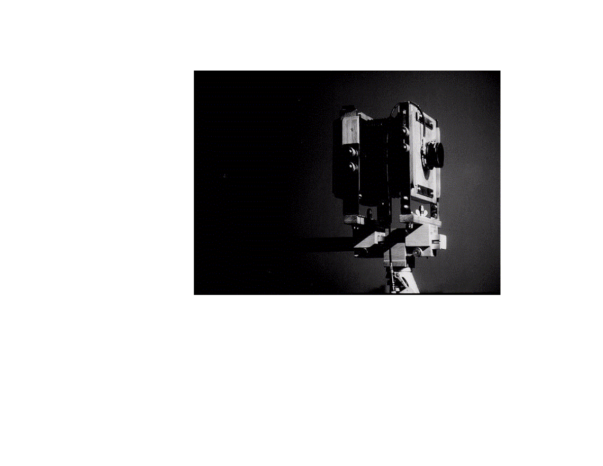
This manual provides plans for a 4 x 5 in. monorail
camera. Materials may amount to $ 60–90, depending
on design and choice of woods and metal parts. The
ground glass and bellows may be bought for a total of
$ 130. If you want to make the ground glass and the
bellows yourself, some references and instructions are
provided. With the optical bench removed the camera
measures approx. 20 x 25 x 10 cm. The weight depends
on your choice of wood and metal parts. A camera built
of oak, my own favorite, will be about 3.0–3.3 kg, the
optical bench included. The optical bench weighs about
1 kg if the sliders and tripod block are made of oak.
Other woods are lighter.
Building a monorail camera is easier than building a
collapsible flatbed (field) camera. Only general
woodworking skills and experience are needed.
Traditional woodworking virtues such as accuracy and
patience are rewarded—and will be reflected in the
final object. To build the camera you need ordinary
woodworking tools: an electric drill (a drill press is
useful, but not necessary), bits for wood and metal, a
bench vise, various saws (backsaw or tenon saw, fret
saw, coping saw and hacksaw), a miter box, a
carpenter’s square (engineer’s try-square), straight tip
and cross-head screwdrivers, metal files, wood files, a
center punch, clamps (miter or corner clamps are useful
but not required), a smoothing plane, a knife, chisels,

11
calipers, a metal ruler, sandpaper of assorted grades. In
addition you will need wood glue, matte black paint for
some internal parts and oil for wood finish.
The materials are mainly wood. The rail is aluminum.
Standards are in 2–3 mm brass. There are some brass
fittings. Various types of screws and threaded inserts or
pronged T-nuts will be needed. Suitable hardwoods are
cherry, mahogany, walnut, rosewood, oak, ash or even
birch. All wood should be well seasoned. You will also
need some plywood. More detailed information about
materials is given below.
Most drawings are to scale 1 : 2. The measurements are
metrical. One crucial measurement (the depth of a
standard film holder) is also given in inches.
A conversion table is found the end of this manual.
A freeware conversion program for Windows can be
downloaded here:
http://home.online.no/~gjon/depth.htm.
2.1 List of Materials
Exact measurements are given in millimeters.
Approximate minimum lengths are in centimeters. My
own choice of materials is determined by the supply of
woods and metal parts in my area. Thus I use 5 or 6
mm oak as the basis of many parts in my design
because planed oak strip or moulding of excellent
quality is easily available with the right dimensions
from my lumber-yard. I have also used teak for
cameras.
Before you start on your camera project, you should
find out what materials are supplied by your local
lumber-yard and hardware store. Many dimensions
may be adjusted to match the materials available. You
may also choose to change some of the details in my
design. The following list of materials is meant only as
a point of departure.
2.1.1 Wood
Frames:
Planed hardwood 30 x 6 mm: approx. 160 cm
Planed hardwood 24 x 6 mm: approx. 160 cm
8 mm plywood: approx. 20 x 40 cm
Planed hardwood 35 x 10 mm: approx. 32 cm (frame
connectors)
Planed hardwood 16 x 6 mm: approx. 80 cm
Veneer strip: 10 x 2 mm: four pieces approx. 15 cm
long.
Lens board:
4 mm birch plywood: 140 x 140 mm
Planed hardwood approx. 20 x 6 mm: approx. 60 cm
Front Panel (undrilled lens board):
4 mm birch plywood: 140 x 140 mm
Planed hardwood approx. 20 x 6 mm: approx. 60 cm

12
Spring Back:
8 mm plywood: 184 x 184 mm (back panel)
Planed hardwood 20 x 6 mm: approx. 80 cm (film
holder seat)
Planed hardwood 10 x 6 mm: approx. 45 cm (film
holder seat)
Planed hardwood 12 x 6 mm: 40 cm (film holder seat)
4 mm birch plywood: approx. 120 x 155 mm (ground
glass frame—exact measurements should be taken from
a film holder)
Planed hardwood 24 x 10 mm: approx. 32 cm (ground
glass frame)
Planed hardwood 24 x 6 mm: approx. 45 cm (ground
glass frame)
Planed hardwood 20 x 5 mm: approx. 22 cm (ground
glass frame)
Standards:
Planed hardwood 30 x 15 mm: approx. 45 cm
Sliders and tripod block:
Planed hardwood 9 x 45 mm: approx. 80 cm
Planed hardwood 15 x 20 mm: approx. 20 cm
Planed hardwood 15 x 6 mm: approx. 20 cm
Planed hardwood 30 x 6 mm: approx. 30 cm
Planed hardwood 18 x 6 mm: approx. 30 cm
4 mm birch plywood: 66 x 45 mm
2.1.2 Metal
Rail:
Aluminum rail 30 x 30 mm: approx. 38 cm
Standards:
Brass 20 x 2 mm: 280 mm (front standard)
Brass 20 x 2 mm: 280 mm (front standard)
Brass 40 x 2 mm: 200 mm (rear standard)
Brass 40 x 2 mm: 200 mm (rear standard)
Angle irons approx. 35 x 35 x 15 mm (two for front
standard)
Lens board lock (retainers):
Brass 125 x 18 x 2 mm (upper lock plate)
Brass 120 x 18 x 2 mm (lower lock plate)
Brass 105 x 10 x 2 mm (cover plate for upper lock)
Spring back lock (retainers):
Brass 40 x 20 x 1 mm (bottom)
Brass 40 x 20 x 1 mm (bottom)
Brass 65 x 45 x 1 mm (top lock)
Brass 65 x 45 x 1 mm (top lock)
Brass 50 x 10 x 1 mm (cover plate for top lock)
Brass 50 x 10 x 1 mm (cover plate for top lock)
Spring back springs:
Leaf springs approx. 165 x 5 mm (two springs)
Ground glass frame:
Brass 100 x 4 x 0.8 mm (for the correct positioning of
the ground glass)
Bellows retainers and reinforcement of corners:

13
Brass 25 x 38 x 1 mm (8 pieces)
Tripod block:
Brass 66 x 45 x 1 mm
2.1.3 Screws, threaded inserts, bolts and nuts
The most common types of screws are not listed.
Length of screws depends on design and is normally
not listed.
Frames:
Control screws (adjustment screws):
Six threaded inserts (or pronged T-nuts): thread
diameter 5 mm (M5)
Six knurled screws or knurled nuts with screws:
diameter 5 mm (M5)
Twelve washers: for screws with diameter 5 mm (M5)
Sliders and tripod block:
For attaching the tripod block to the tripod:
One threaded insert (or pronged T-nut) for the tripod
block: inner diameter 3/8 inch or 10 mm (M10). The
threaded insert should fit the tripod screw, with or
without a tripod screw adapter.
For attaching the crosspiece (“beam”) of the standards
to the sliders:
Two hex-head brass bolts: diameter 6 mm (M6), length
depends on design
Two knurled screws or knurled nuts with screws:
diameter 6 mm (M6)
Two washers for M6 (6 mm) screws (to go under the
wing nuts)
Two brass wing nuts: diameter 6 mm (M6)
Two brass cap nuts (acorn nuts): diameter 6 mm (M6)
Fastening screws for the sliders:
Three brass bolts: diameter 5 mm (M5), length approx.
70 mm
Three brass wing nuts: diameter 5 mm (M5)
Three brass cap nuts (acorn nuts): diameter 5 mm (M5)
Six washers: for screws with diameter 5 mm (M5)
Standards:
For attaching the brass uprights to the crosspiece:
Eight cheese-head (flatheaded) brass machine screws:
length 24 mm
Eight brass cap nuts (acorn nuts)
For the angle-irons:
Eight brass cheese-head machine screws: length 6 mm
Eight brass cap nuts (acorn nuts)
Notes: Pronged T-nuts are sometimes also referred to
as captive nuts or spiked nuts. On how to make knurled
screws from knurled nuts and machine screws, see
section 4.6 and Figure 26.
14
3 The Basic Outline
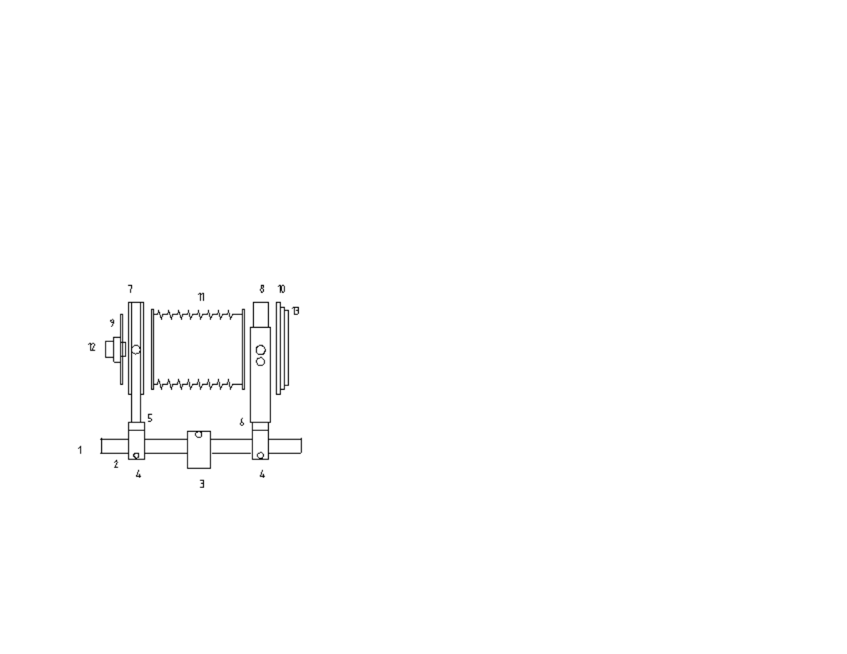
The camera proper rests on an optical bench (1). The
optical bench consists of an aluminum rail (2), a tripod
block (3) and two sliders (4).
The sliders carry the front and rear standards (5 and 6).
The standards in turn hold the front and rear frames (7
and 8). The lens board (9) is attached to the front
frame, the spring back (10) to the rear frame. Between
the front and rear frames is the bellows (11).
Exploded and simplified view of the monorail camera
A lens (12) is mounted on the lens board. The spring
back consists of a back panel, a film holder seat and a
ground glass frame (13). The ground glass frame holds
the ground glass (14) and fits into the film holder seat
(15). Two flat (leaf) springs (16) press the ground glass
frame against the back panel. The ground glass frame
holds the film holder in place when the holder is
inserted.
A simple lock mechanism (17) attaches the spring back
to the rear frame. The spring back may be positioned
for horizontal or vertical formats. Changes from the
horizontal to the vertical format are made by sliding the
two upper locks open, removing the back, rotating it 90
degrees, repositioning it and sliding the locks back in
place.
Threaded inserts (or pronged T-nuts) and knurled
screws (18) are used for holding and locking the front
and rear frames in the standards. On either side of the
frames, between the frames and the standards, there is a
frame connector (21). Wing screws and knurled nuts
(19) are used for fastening or locking the sliders when
focusing. Bolts and wing nuts (20) are used for
fastening the frames to the sliders. A lens board lock
(22 and 23) attaches the lens board to the front frame.
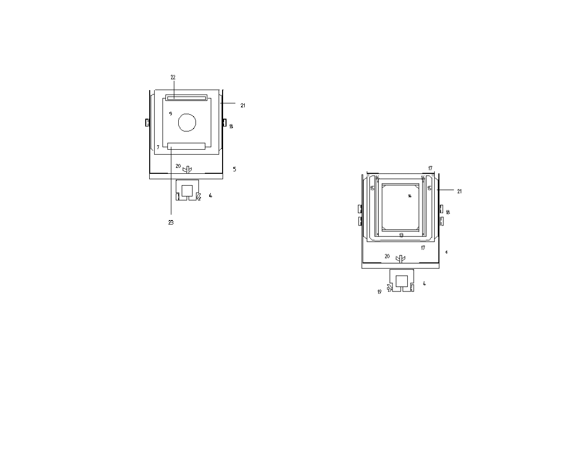
15
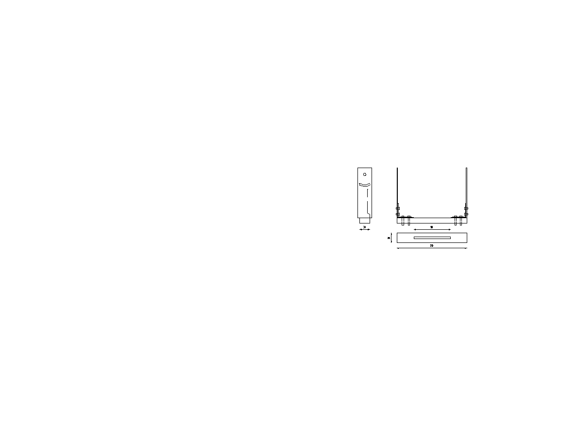
Front view of the monorail camera.
The position of the ground glass is the one really
critical measurement in the camera design. The ground
surface (focusing plane) of the ground glass has to
coincide with the film plane when a film holder is
inserted.
Other important measurements are the dimensions of
the front and rear standards including the positioning of
the holes and slots. These determine the potential rise
and fall of the front frame, and the degree of tilt of the
rear frame.
The internal measurements of the front and rear frames
should accommodate a standard bellows. The film
holder seat in the spring back should be made to the
measurements of a film holder.
Most other measurements of your camera may differ to
some extent from those given in these plans if you want
to change the design outlined here.
End view of the monorail camera
16
4 The Construction Process
Make the front and rear frames first. Then make the
lens board and the spring back. Finally make the
standards and the optical bench.
4.1 The Front and Rear Frames
The frames and the bellows constitute the camera
proper. The frames are made of two strips of planed
hardwood, 30 x 6 mm and 24 x 6 mm, which are glued
together to make a strip 30 x 12 mm with a 6 x 6 mm
rabbet (Figures 4 and 5).
Front frame
Eight pieces, each 184 mm long, are cut and mitered 45
degrees. (The corners may be dovetailed instead of
mitered, but dovetailing is not necessary.) The internal
measurements are 160 x 160 x 24 mm to accommodate
a standard bellows. (Note: The frames of a standard
Cambo bellows are 162 x 162 mm. The bellows frames
may be cut to 160 x 160 mm, or you may increase the
internal measurements by 2–3 mm.)
Four pieces are glued together to form a frame. The
external measurements are 184 x 184 x 30mm. Corner
clamps (used for gluing picture frames) are useful for
holding the pieces in place and for exerting pressure.
They are inexpensive and can be found in a hardware
store.
The next step is to make two plywood squares, with the
same external dimensions, to go inside the frames, one
for the front frame and one for the back. They are made
of 8 mm plywood, 160 x 160 mm. The plywood square
for the front frame has a cutout 120 x 120 mm (Figure
6). The cutout in the piece for the rear frame is 130 x
130 mm (Figure 10). The plywood squares are glued to
the inside of the frames (Figures 7 and 11).
(The front and rear frames may also be made with a
rabbet of 10 x 6 mm, instead of 6 x 6 mm. The
plywood squares will then have be made of 4 mm
plywood, 172 x 172 x 4 mm. The cutouts are the same
as in the description above. The squares are then glued
to the rabbets in the frames.)
For the front frame four strips of 172 x 16 x 6 mm
hardwood are mitered to form a frame to go in the
rabbet on top of the plywood (Figure 4). The pieces are
glued to the plywood and the rabbet in the front frame.
The front frame will now have an opening 140 x 140
17
mm for the lens board. Thin strips of wood (veneer),
140 x 10 x 2 mm, are glued to the plywood to
accommodate the lens board which is 4 mm thick
(Figures 4 and 13).
Front frame with "frame connector"
The front and rear frames will later be attached to the
standards with threaded inserts (or pronged T-nuts) and
knurled screws or knobs. On either side of the frames,
between the frames and the standards, a piece 155 x 35
x 10 mm is added for the threaded insert (Figures 8 and
12). Each piece, or “frame connector”, is fastened to
the frame with two screws. The use of “frame
connectors” may be unique to my camera design. The
advantage is that holes for threaded inserts are made in
the “frame connectors”, not in the frames proper. If you
happen to be inaccurate while drilling the holes for the
inserts, your frame is not spoiled. You just make a new
“frame connector” and drill a new hole.
It also means that at a later stage, when you have been
experimenting with your camera for some time and
have become familiar with camera movements, you
may easily change the pivot points for tilt (by moving
the holes for the inserts forward or back) if you find
that practical for your purposes. You just make a
couple of new “frame connectors”, put the holes where
you want them for your camera movements, and fasten
the pieces to the frames.
In other words, the “frame connectors” are a safeguard
against inaccuracies while you are building the camera
and they give you greater flexibility for customizing
your camera. Note that the holes for the threaded
inserts should be level with the optical axis, i.e. an axis
90 degrees on the center of your lens.
The thickness of the frame connectors depends on the
size of your threaded inserts. Many inserts will need a
thickness (depth) of 12 mm or 15 mm. In this design
the frame connectors are 10 mm which is sufficient if
you are using pronged T-nuts. If you make the frame
connectors thicker you will also have to make the
beams of the standards longer. Because the exact
dimensions of the frame connectors and the positioning
of the holes for the threaded inserts or pronged T-nuts
depend on the design and dimensions of the standards,
it is suggested you make the frame connectors in
conjunction with the standards. See section 4.6.
18
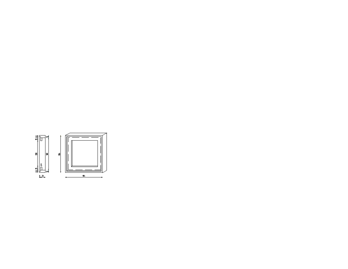
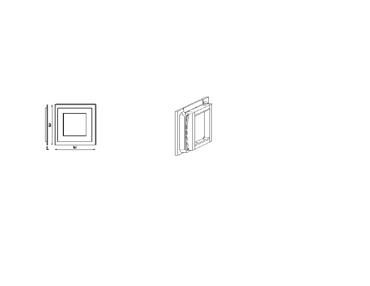
4.2 The Lens Board
The lens board is made of 4 mm birch plywood or other
hard plywood (Figure 13). It may also be made of
strips of 4 mm hardwood glued together to make a
square board. If you use the latter method, care has to
be taken that the board is plane and that it does not
warp.
Lens board
The measurements are 140 x 140 x 4 mm. A light trap
(baffle) on the inside of the lens board is made by
gluing a frame of four pieces of 20 x 6 mm hardwood
on to the back of the lens board. The light trap frame
fits into the 120 x 120 mm cutout in the plywood in the
front frame (Figure 4). To cut a hole for the lens, see
section 4.8.
You should make an extra panel the same size as the
lens board to replace the lens board when the lens
board is not attached. This panel—an undrilled lens
board— helps keep dust away from the interior of the
camera when the camera is stored.
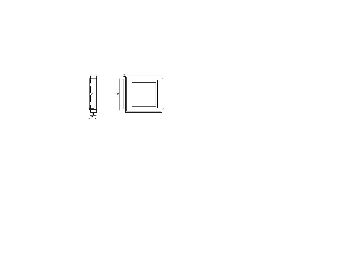
4.3 The Spring Back
Spring back
The panel of the spring back is made of plywood, 184 x
184 x 8 mm (Figures 14, 15 and 16). It may also be
made of a number of pieces of hardwood joined
together. In the latter case great care has to be taken
that the spring back is plane and that it does not warp.
The back panel has a cutout of 100 x 120 mm. A frame
made of four pieces of hardwood, 172 x 20 x 6 mm, is
glued to the inside of the back panel. This frame serves
as a light trap mechanism, similar to the light trap
19
frame of the lens board. It fits into the rabbet in the rear
frame and helps hold the spring back in place.
Use a film holder to mark the critical measurements of
the spring back. Draw a film holder on graph paper.
Use a copier to make a copy on a transparency. Place
the transparency on the back panel. Mark the critical
measurements. My own drawing of a standard film
holder is reproduced in Figure 32. Note that the
external dimensions of standard film holders for 4 x 5
in. and 9 x 12 cm sheet film are the same. The depth of
the film holders is also the same.
Spring back
The groove for the locating ridge of the film holder
(Figure 16) may be routed or cut carefully with a sharp
knife and chisel. The groove should cross the direction
of the grain in the surface layer of the plywood. Use a
thin file to clean the groove. The groove holds the film
holder in place and also serves as a light trap.
The film holder seat (Figure 17) is glued to the back
panel and fastened by screws from the inside. The
internal measurements are taken from a film holder.
Gound glass frame (simple design)
This edition of my book offers two designs of the
ground glass frame. If you choose my basic design of a
ground glass frame, suitable wood for the film holder
seat walls is 20 x 6 mm hardwood strips glued together
to form pieces 20 mm wide and 18 mm thick. Note that
the two vertical pieces have a rabbet approx. 10 x 6
mm to accommodate the leaf springs holding the
ground glass frame (Figure 17).
If you decide to use my more elaborate design of a
ground glass frame, the film holder seat walls should
be approx. 20 x 12 mm with a rabbet of approx. 10 x 6
mm. See figures and detailed instructions in the
Addendum on page 37. The following instructions are
for the basic ground glass frame.

20
Ground glass frame (advanced design)
Get a ground glass before you make the ground glass
frame. A standard ground glass is fairly inexpensive
and may be bought from a view camera dealer. An
intense screen or a ground glass with a fresnel lens in
many circumstances gives a brighter viewing image but
costs more than a simple ground glass and are not
really needed. Usually the corners of the ground glass
are cut off to make it easier to check on vignetting (see
section 8.2) and to permit movement of air when the
bellows is extended or compressed.
A fresnel lens is a thin sheet of plastic with concentric
stepped rings which works like a condenser lens. The
fresnel lens should be placed on top of the ground
glass, between the ground glass and the photographer,
so that the focusing surface of the ground glass is not
displaced. The fresnel patterns, which should face the
photographer, distribute the image brightness over the
ground glass and make the corners lighter.
As mentioned above you may choose between two
ground glass frame designs. If you choose the simple
design (Figures 18 and 19), the ground glass frame is
made of 4 mm birch plywood and a frame of 10 x 24
mm hardwood. A rectangular piece is cut from the
plywood to fit in the film holder seat (approx. 120 x
155 mm). Then a rectangular window (cutout) is made
in the piece of plywood (approx. 101 x 121 mm). The
width of the window should be the same as the width of
the ground glass. The height should be a few mm less
than the ground glass, and slightly larger than the
viewing area of the ground glass. The viewing area is
normally marked by black lines. The hardwood frame
is then glued to the plywood. Two pieces of hardwood
(approx. 4 x 18 mm) are cut the same length as the
internal width of the ground glass frame. These are
locks or retainers for keeping the ground glass in place.
They are screwed on to the bottom and top walls of the
ground glass assembly when the ground glass is
positioned in the frame.
Positioning the ground glass is the most critical detail
in the design. The focusing surface of the ground glass
has to be in the same position as the emulsion of the
film when a film holder is inserted. The critical
measurement is 4.8 mm. (The ANSI standard for the
depth of a standard film holder is 0.1972" plus minus
0.007". Most film has a base of 0.007". When film is
loaded in the film holder, the depth is 0.190". This is
the measurement used by Sinar cameras. Wisner
cameras use a compromise of 0.192" to allow for wear
on the wood and because Tech Pan film has a base of

21
0.004"). 4.8 mm is the distance from the external
surface of the birch plywood to the focusing surface of
the ground glass. Since the plywood is 4 mm, a 0.8 mm
strip of brass is placed between the plywood and the
ground glass at the top and bottom ends of the frame.
You may use a Vernier caliper gauge to check the
measurement. Vernier calipers take measurements to
0.1 mm or less. They are available in some hardware
stores for approx. $ 20. Some hardware stores also have
reasonable micrometers. Both may be bought from
Micro-Tools at http://www.micro-tools.com/
Note 1: If you you are building a 5 x 7 in. camera, the
ANSI standard for the depth of a 5 x 7 film holder is
0.228" plus minus 0.010", or 5.8 mm plus minus 0.25
mm. When 0.007" film is loaded, the depth is 0.221" or
5.6 mm.
Note 2: If you are building an 8 x 10 in. camera, the
ANSI standard for the depth of an 8 x 10 film holder is
0.260" plus minus 0.016", or 6.6 mm plus minus 0.4
mm. When film is loaded, the depth is 0.253" or 6.4
mm.
A spring mechanism (Figures 14 and 15) attaches the
ground glass frame to the film holder seat. The leaf
springs may be made from the spring used in “flexible
sink and drain cleaners” (a long flexible spring with a
ball on one end used for cleaning stopped kitchen
drains etc.) which available in hardware stores. They
are inexpensive. You may also use metal from a
bandsaw blade or other saw blades where the teeth
have been ground or filed off. The leaf springs of a car
windshield wiper can also be used for springs. Some
watchmakers may also have some suitable springs from
older clocks lying around.
You cut two pieces approximately 170 mm each from
the spring. The leaf springs may be fastened to the
rabbet in the film holder seat with one or two screws
each. You may consider placing a small piece of wood
between the screws and the leaf spring. You determine
the pressure the leaf springs exert by making the piece
of wood shorter or longer. My more elaborate ground
glass frame suggests a different retaining mechanism
for the leaf springs.
Either end of the spring rests on a screw or stud in the
ground glass frame (simple ground glass frame design)
or on a piece of brass (more elaborate ground glass
design) and thus exerts pressure on the ground glass
frame. Practice with inserting a film holder to check
that the pressure is right. The ends of the leaf springs
may be bent with a pair of pliers to form a U around the
studs. Make sure the springs are long enough for the
necessary movements.
The type of leaf spring mechanism used in this camera
design dates back to around 1860 in the history of
camera making. It became popular in the US from the
1890's onwards. An interesting alternative spring
mechanism (”rat-trap” style) is found in Partridge
1992.
22
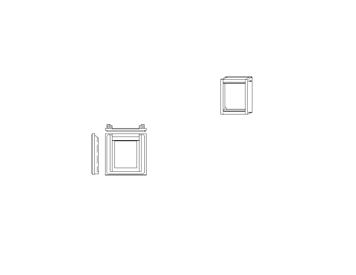
4.4 Lock Mechanism for the Spring Back
The spring back is held in place in the rear frame by
two L-shaped brass pieces at the bottom of the frame
and two movable locks with a cover plate at the top of
the frame. The locks are made of 1 mm brass. This
mechanism makes changes from the horizontal to the
vertical format easy. (Figures 20 and 21). Use a file to
smooth the corners of these and other metal parts.
4.5 Lock Mechanism for the Lens Board
Large format lenses are mounted on lens boards. To
change the lens you change the lens board. There are
various types of mechanisms for holding the lens board
in place. For this camera the lens board locks are three
pieces of 2 mm brass. The lower lens board lock plate
is 120 x 18 x 2 mm and is fastened to the front frame
by two screws. The upper lock consists of the upper
lens board lock plate which is 125 x 18 x 2 mm and a
cover plate of 105 x 10 x 2 mm. The larger piece has
two slanted slots for screws and serves as a sliding
catch (Figure 20).
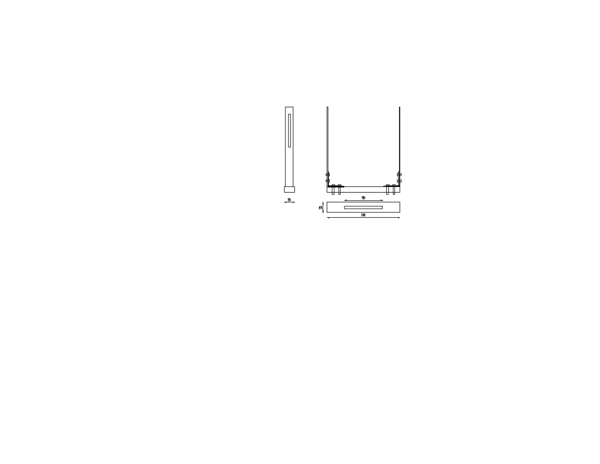
4.6 Standards
Large format cameras have on-axis tilt or base-tilt.
Some have both. On-axis tilt means that the front and
rear frames tilt on the optical axis (center of lens or
film plane). Most monorail cameras have on-axis tilt.
Base-tilt means that the pivot point for the tilt is located
along the bed of the camera. Field cameras generally
have base-tilt for the rear frame.
Front standard
The standards are made of a hardwood ”beam” or
crosspiece (approx. 210 x 30 x 15 mm) and two L-
shaped uprights in 2-3 mm brass. You may cut the
brass yourself with a hacksaw or have a machine shop
do it for you. Each hardwood beam has a
70–110 mm long slot for the slider attachment screw.
The size of the screw determines the width of the slot.
I use M6 (6 mm) screws. The slot makes possible the
shift movements of the front and rear frames.
The uprights of the front standard are two L-shaped
strips of brass, 280 x 20 x 2 mm. The vertical part of
the L-shape is 230 mm. A 95 mm long slot is made in
each standard for the front frame control screw. Use a
23
drill and a fretsaw to make the slot. This slot is for the
rise and fall movement of the front frame. The width of
the slot is determined by the type of screw used to hold
the front frame. I use M5 (5 mm) screws. The control
screws (knurled screws) go into the threaded inserts (or
pronged T-nuts) in the frame connectors. The L-shaped
uprights are fixed to the beam by cheese-head (flat-
headed) machine screws. I use M5 (5 mm) screws here.
The screws are fastened with cap nuts (acorn nuts)
under the hardwood beam. You may also use ordinary
nuts with washers. The corners of the L-shaped
uprights may be reinforced by angle-irons. If necessary
put thin washers between the brass uprights and the
angle-irons.
The uprights of the rear standard are two L-shaped
strips of brass, 200 x 40 x 2 mm. The vertical part of
the L-shape is 150 mm. The rear standards hold the rear
frame by means of two control screws (knurled screws)
on either side. One screw is for the pivot hole, the other
for adjustments (camera movements). The slot for the
adjustment screw is shaped like an arc to allow tilt
movements. The center of the arc is the center of the
pivot hole. The positioning of the circular slot
determines the degree of tilt possible. I suggest the
distance to the pivot hole be 25–30 mm.
Note that when the film holder is in the horizontal
position the maximum degree of backward tilt is
determined by the positioning of the rear standard
uprights. If the frame connectors are 10 mm thick, as
suggested above in section 4.1, the handle of the film
holder dark slide will hit the standard upright when the
tilt is more than approx. 18–20 degrees (depending on
your positioning of the frame connectors and the
positioning of the adjustment slot). If you want more
backward tilt, you may (1) place the insert for the
control screw further to the front of the frame
connector piece or (2) shape the rear brass uprights to
accept more tilt by making a cutout in the lower part of
the upright (Figure 23).
Rear standard
What is said above applies only to backward tilt of the
rear frame when the film holder is in the horizontal
position, not to the forward tilt of the frame. Forward
tilt of the rear frame is not limited by the shape of the
rear standard, only by the control screw arc. Nor is tilt
limited by the standards when the film holder is in the
vertical position.
The front standards will accept 80 mm rise (more than
is needed) and about 15 mm fall of the front frame. If
you want more fall you just make the rear upright

24
longer and raise the pivot hole and the arced slot for the
control screw. If you only occasionally need more front
fall you may set up your camera with the monorail not
in the horizontal position but slanting slightly forward.
My experience is that I need more front rise than fall.
The standards may also be made only of hardwood
(beam and uprights). Metal uprights may look better
but wooden uprights conduct less vibration. My
personal choice is 2 mm brass reinforced with angle-
irons. Vibration has not been a problem.
The front and rear frames are attached to the standards
with knurled screws or knobs. The thread diameter is 5
mm (M5). If you have problems finding the right type
of screws, you may screw a cheese-head (flat-headed)
machine screw into a knurled nut, apply some torque,
and thus get a beautiful knurled screw with the right
dimensions (Figure 26). I use zinc-coated knurled nuts
and brass screws for making control knobs. The screws
fit into the threaded inserts (or pronged T-nuts) in the
frame connectors. A washer is placed between the
knurled screw and the standard. Another washer is
placed between the standard and the frame connector.
The frame connectors should be fastened to the frames
with two screws each. The back of the connectors
should be flush with the back of the frames.
Note that the positioning of the holes for the control
screws affects camera movements. I suggest the holes
be placed 15 mm from the front of the frame
connectors (Figure 24). As the dimensions of your
camera may differ somewhat from my drawings, you
should make sketches based on the exact dimensions of
your camera before you decide on the positioning of
the holes for the control screws in the rear standard.
You may use a protractor to measure tilt angles.
When the camera is set up, the beams (crosspieces) of
the standards rest on the sliders. The 6 mm (M6) screw
in each slider fits in the slot in the beam. A brass wing
nut is used for locking. A washer is placed under the
nut. The end of the 6 mm (M6) screw may be capped
with a brass cap nut (acorn nut). Knurled nuts or
locking levers may be used instead of wing nuts. My
preference is for brass wing nuts because they are easy
to turn and because I avoid plastic knobs or levers for
esthetic reasons. Some black plastic levers go well
with teak, however.
4.7 The Optical Bench
The optical bench consists of an aluminum rail, 30 x 30
x 380 mm), a tripod block and two sliders for carrying
the standards. The sliders are the focusing system of
the camera.
25
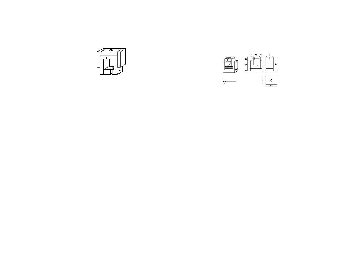
Slider
The sliders and the tripod block are basically of the
same design (Figures 25 and 26). The sliders have an
M6 (6 mm) screw for the standards; the tripod block
has a 3/8 inch or a 10 mm threaded insert (or pronged
T-nut) for the tripod screw. (A standard ¼ inch tripod
screw adapter will fit both the 3/8 inch and the 10 mm
insert.) The sliders and the tripod block are made of
hardwood, preferably of a number of pieces that are
glued together. I use 6 mm and 9 mm hardwood strips.
In my design the sliders are 66 x 66 x 30 mm or 66 x
66 x 45 mm. Thirty mm should be sufficient depth to
produce a sturdy slider but 45 may be even sturdier.
Forty-five mm depth may be too much if you are using
wide angle lenses. However, you can set up your
camera with the tripod block in front of the sliders to
reduce the distance between the front and rear frames.
The sliders and the tripod block may also be made of
metal or Delrin, a strong plastic material. I have good
experience with wood, which I feel gives the right
friction when focusing. Care should be taken that the
internal measurements of the sliders are accurate (30 x
30 mm). They should be made tight and be adjusted by
careful sanding or filing.
Tripod block with screws and brass plate
A hole is drilled in each slider for an M6 (6 mm) hex-
head bolt to hold the beam of the front and rear
standards. The bolt is inserted from inside the slider
before the bottom pieces of the sliders are glued in
place (Figure 25). An M5 (5 mm) wing screw with a
knurled nut is used as a locking screw in each slider. If
you have problems finding a wing screw long enough,
you may make one by screwing a long machine screw
into a wing nut (see the preceding section and Figure
26). On top of the tripod block you may fasten a 2 mm
brass plate with four counter-sunk screws. At the center
of the plate there is a hole slightly larger than the tripod
socket.
4.8 Mounting the Lens on the Lens Board

26
Mark the center of the lens board. Use a compass to
draw a circle the size of the rear thread of your lens.
Cut the hole with a coping saw or fretsaw. Use a file
and sandpaper to make the hole perfectly circular and
slightly larger than the rear thread of your lens but
smaller than the retaining ring of the lens. Place the
rear thread of the lens in the hole and fasten the
retaining ring. Note that different lenses will have rear
rings with different diameters depending on the type of
shutter. Mounting the lens on the lens board should be
the last step in the construction of the camera.
4.9 Attaching the Bellows
The bellows may be glued to the front and rear frames.
An interchangeable bellows, however, has benefits
over a non-removable bellows. You may want to
remove the bellows for giving your camera another
coat of oil, or you may want to have the freedom to use
a bag bellows with short lenses, or to make an
accessory frame for a second bellows for extreme
close-ups or a long telephoto lens.
My personal choice is a kind of brass retaining lock
made of 1 mm brass sheet. The lock also serves to
strengthen the corners of the frames. However, since
each piece is attached with two screws, this mechanism
is not practical for frequent or quick change of bellows
(Figure 27).
An alternative solution, which makes change of
bellows fairly easy, is to attach the bellows to the
frames with one screw in each corner of the bellows
frame.
4.10 Finishing the Wood
Internal wooden parts should be painted matte black.
The external surfaces of the hardwood parts should be
given one or several coats of oil or your favorite wood
finish suitable for the hardwood you have chosen.
Brass parts should be polished with brass polish from
time to time.
5 Testing the Camera

27
5.1 Testing for Light Leaks
If you have followed the instructions and your work
has been accurate there is little danger that the camera
is not light proof. However, to test it for light leaks you
may place it in bright light for half an hour with a film
holder inserted and the film holder’s dark slide pulled
out while the shutter is closed. When you develop the
film there should be no fogging. If you have made the
bellows yourself or have bought a second hand bellows
and want to test it for pinholes, you can use the same
method. You can also put the camera in a dark room
and put a flashlight into the bellows (ground glass
holder removed). Light will then leak from pinholes.
5.2 Testing Focusing
Put a long folding rule or a long tape measure on the
floor of room. Place objects at regular intervals along
the rule. Expose with maximum aperture to reduce
depth of field. Develop, check results. Use a depth of
field scale (or calculations) to check the results. The
front and rear frames should be in a neutral position (no
tilt) when you are testing.
6 Appendices
6.1 Making a Ground Glass
This manual assumes that you buy the ground glass.
They are fairly inexpensive for 4 x 5 cameras but rather
expensive for larger formats. A brightscreen or a
ground glass with a fresnel lens give a brighter viewing
image in many circumstances. A standard ground glass
may cost about $ 20–30 and is available from large
format camera dealers. Brightscreens and fresnel lenses
will be more expensive.
Sheets of ground glass may also be bought from a
glazier. Coarse-grain ground glass makes focusing on
finer details difficult. You may also make a ground
glass of excellent quality yourself. Take a sheet of plate
glass (about 12 x 12 in.), spread half a teaspoonful of
# 600 carborundum (silicon carbide) or # 500
corundum grit onto the plate, saturate the grit with a
teaspoonful of water. The 4 x 5 ground glass-to-be is
then placed on the grit and gently rotated. The grinding
may take about five to ten minutes. You may find it
useful to have an extra ground glass in case your
regular ground glass breaks. Carborundum should be
available in lapidary shops.
6.2 Making a Bellows
This manual also assumes that you buy a standard
bellows or has a bellows custom made for you. You
will find some bellows makers listed under Addresses
at the end of the book or in my View Camera
Construction FAQ at
28
http://home.online.no/~gjon/lffaq.htm. Standard
bellows for most brands of cameras tend to be
expensive. However, there is a standard Cambo
bellows which is available at a price of approximately $
105. A custom made bellows may be about $ 130. If
you want to make the bellows yourself, useful advice is
found in West 1995, pp. 35–44, in Robinson 1996,
Romney 1990, and in Camera Making, a fascinating
collection of articles from the British magazine
Amateur Photographer 1887–1995. Hasluck 1907 is an
old valuable source (chapter ”Miscellaneous Items”).
An excellent online source is Doug Bardell's web site
at http://www.cyberbeach.net/~dbardell/bellows.html.
To make a bellows you will need two kinds of fabrics,
one for the inner lining, the other for the outer
covering. For the lining you may use dull black fabric
or rubberized nylon. The cover may be rubberized
nylon, fabric used for lightproof curtains, or thin
leather. The latter may be a more expensive option.
For the ribs you will need thin card stock.
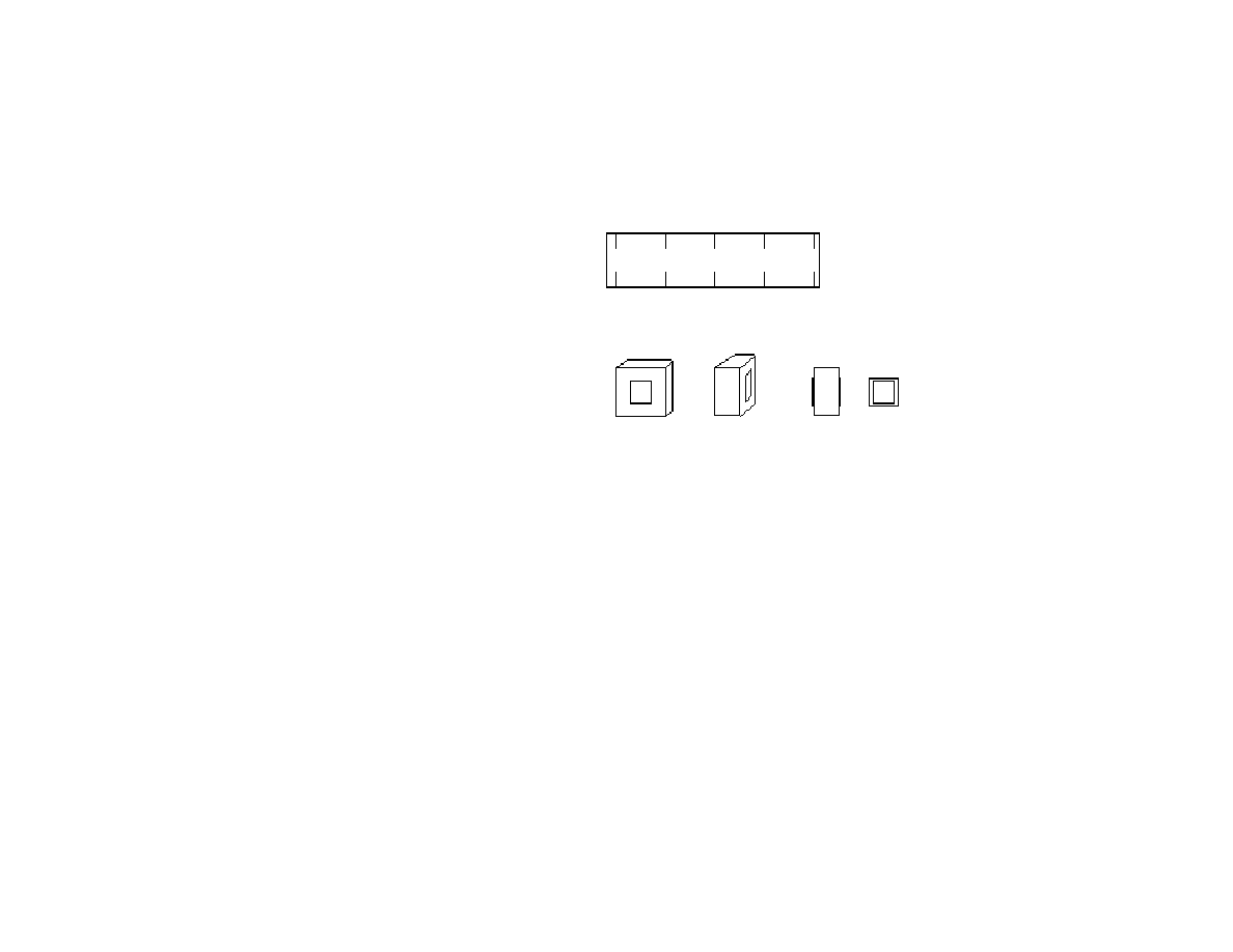
To make a bag bellows for wide-angle photography is
considerably easier than making a pleated bellows
(Figure 28). Bag bellows are used to facilitate camera
movements when you are using wide-angle lenses.
They are also useful for normal lenses if you need a lot
of movements, e.g. front rise or fall. To make a bag
bellows you need some light proof material, approx. 30
x 120 cm (available in some stores which sell curtains
and shades and from darkroom equipment dealers),
textile glue and two 3–4 mm plywood squares, 160 x
160 mm for the bellows frames.
Bag bellows
Make a paper dummy first. Cut the material as in
Figure 28. A cutout, 130 x 130 mm, is made in the
plywood squares. The bellows is glued to the plywood
squares. The frames have to accommodate the bellows
retaining locks of the front and rear frames. You may
also glue two smaller squares, 140 x 140 mm with a
cutout 130 x 130 mm, on the inside of the bellows to
make the construction stronger. Make sure the internal
of your bellows does not reflect light. You may also
use thin leather for the bellows and aluminum for the
bellows frames. The bellows in Figure 28 has a
maximum extension of approx. 220 mm. If you need a
larger bellows you just increase the dimensions.

29
6.3 Making a Camera Case
The camera with accessories fits easily in a standard
backpack. The monorail with the tripod block and
sliders attached is taken off the camera proper and
packed separately. So is the lens board with lens. You
should have an undrilled lens board for the front frame
to keep dust away when your lens board with the lens is
removed. The lens board with the lens should be
packed carefully to deaden shocks. Even though it
takes some space, you may decide to make a special
case for the lens board (Figure 29).
A standard backpack or a bag is most practical for
transporting your camera. For storing it you may make
a case of aluminum profiles and 7 mm laminated
flooring. An alternative to laminated flooring is
plywood. My own camera case has a compartment
structure of teak which fits the internal measurements
of the case. The camera with standards goes into one
compartment, the rail in another, accessories in a third,
etc. (Figure 30).
6.4 Step-up Adapter for the 5 x 7 Format
A step-up adapter for the 5 x 7 inch format may replace
the 4 x 5 inch spring back. A basic sketch is found in
Figure 31. Unlike the rest of the plans in this manual,
this sketch has not been tested by my own experience.
I have not so far made a step-up adapter myself since
I do not have a lens for this format. The basic
construction, however, dates back to the 1880’s in the
history of camera making. A similar step-up adapter is
available today for Osaka, Nagaoka, Wista and other
field cameras. I offer the sketch merely for inspiration
for those who would like to try to build one. The sketch
is for a tapered step-up adapter. An adapter with
rectangular sides is easier to make and should work
equally well. The step-up panel and film holder seat
should be made to the measurements of a film holder.
Since the film plane is pushed rather far back from the
standards camera movements are, of course, altered.
6.5 Scaling the Plans up for an 8 x 10 Camera
The plans in this book may be scaled up for building an
8 x 10 camera. The critical measurements—the depth
of film holders—are found in section 4.3 above. If you
decide to build an 8 x 10 camera, you should start with
the back frame. Get an 8 x 10 film holder and adapt the
dimensions to the film holder. In order to reduce
weight and bulk you may consider making the front
frame smaller than the rear frame and have a tapered
bellows instead of a square one. You may use the plans
and dimensions in this book for the front frame. In fact,
if you have already built a 4 x 5 camera based on the
plans in this book, the front frame may be used also for
an 8 x 10 camera, provided the bellows is detachable.
When you have made the front and rear frames, and the
spring back, you should make the standards and the
optical bench. Wood may be a better choice than metal
for the standards of an 8 x 10 camera. Before you make
the standards you have to decide what camera

30
movements you want. The optical bench may be built
around a monorail as in this book, or you may use two
rails as in Rudolf Mittelmann's design, at
http://www.geocities.com/SoHo/Suite/7013/foto/index.
html
For a beautiful and functional 8 x 10 camera built of
teak and based on my design, and with a bellows made
according to Doug Bardell's instructions, see Marcus
Carlsson's camera, at
http://home.online.no/~gjon/marcus.htm.
For an 8 x 10 camera under construction, see my web
pages at: http://home.online.no/~gjon/lf8x10.htm.
Lenses in shutters for 8 x 10 cameras tend to be
expensive. Lenses in barrel, e.g. processing lenses
which are not mounted in a shutter, are fairly
inexpensive on the used market, for instance on eBay.
With expose times of 1 second or more you may use a
lens cap for shutter, or you may buy a reasonable
Packard shutter. See my View Camera Construction
FAQ at http://home.online.no/~gjon/lffaq.htm.
7 Notes on Lenses for Beginners
7.1 Covering Power of Lenses
Lenses for large format cameras have to allow for
camera movements—rise and fall, shift, tilt and swing.
Therefore the circle of good definition or image
circle—the circular area in the image plane where the
lens forms an image of acceptable definition—has to be
larger than a film sheet itself. This is a major difference
between lenses for large format cameras and lenses for
rigid-bodied 35 mm cameras or medium format
cameras.
The diagonal of a 4 x 5 in. film sheet is is approx.150
mm. If a lens has a circle of good definition with a
diagonal of 210 mm, there will be a total of approx. 60
–70 mm for rise/fall or right/left shift, distributed on
each side. More exactly, there will be 38 mm for rise
and fall, 33 mm for lateral shift on either side when the
film is the horizontal position.
The circle of good definition (lens coverage) is a
crucial specification to look for when buying a lens. It
should be noted that stopping down a lens usually
increases the circle. Lens manufacturers typically
specify the covering power of a lens with the
diaphragm set at f/22. If a larger aperture is used, the
covering power will decrease. A normal lens with a
focal length of 150 mm will typically have an image
circle of approx. 210 mm at f/22; at f/5.6 the circle may
be approx. 174 mm. At f/22 the angle of view is 70
degrees, at f/5.6 only 60 degrees. Lenses with a large
circle of good definition generally have more lens
elements than lenses with less covering power.

31
7.2 Normal, Wide-Angle and Telephoto Lenses
Normal lenses have a focal length corresponding more
or less to the diagonal of the film. A typical normal
lens
for a 4 x 5 in. camera has a focal length of 150 mm or
180 mm. 210 mm is also considered a normal lens,
sometimes referred to as a long normal.
Wide-angle lenses have a focal length shorter than the
film sheet diagonal. For 4 x 5 in. cameras the focal
length of wide-angles may extend from 65 to 120 mm.
A typical wide-angle lens would be 90 mm. To use a
short wide-angle lens you may need a recessed lens
board. Instead of pleated bellows a bag bellows is often
used to facilitate camera movements.
A telephoto lens for a 4 x 5 in. camera typically has a
focal length of 360 mm. Telephoto lenses and short
wide-angle lenses are expensive.
The following table indicates how large format lenses
for 4 x 5 compare to lenses for 35 mm cameras or
medium format cameras.
Film
D
iagon
al
Focal length
35 mm
43 mm
25
32
43
52 60 90
6x6 cm
80 mm
46
58
75
95 110
165
6x9 cm
100 mm
58
75
100
120 135 210
4x5 in.
150 mm
90
120
150
180 210 320
7.3 Buying a Lens
When you buy a lens you should plan ahead. Because
lenses are expensive most people will start out with a
single lens, usually a normal lens. A lens 150–210 mm
is often regarded as a good choice for most general
purposes. If you are planning to get a wide-angle lens
later, or a telephoto lens, this should be taken into
consideration when settling on a focal length for a first
lens. Steve Simmons (1987) gives good advice on
building a lens system for a 4 x 5 camera. A lens with a
large circle of good definition, a lens allowing camera
movements, should be preferred to the more
inexpensive lenses with less covering power.
A new lens is expensive. Second hand lenses are
available in some stores or are advertised in photo
magazines. In the US, the Shutterbug magazine is often
referred to as a good source. On the Internet, eBay is a
good source: http://www.ebay.com/ For black and
white photography an older lens may give good results.
Some sources for used lenses and other equipment are
listed under Addresses at the end of this book. Sources
for information about lenses are listed under Internet
sources.

32
8 Operating the Camera
One of the most readable introductions to large format
photography is Steve Simmons: Using the View
Camera—A Creative Guide to Large Format
Photography (New York: Amphoto 1987, revised
edition 1992). I recommend the book warmly. The
following is only meant as a very simple guide.
8.1 Loading Film Holders
Sheet film generally comes in packages of 10, 25 or
100 sheets. The sheets are often packaged in a foil in a
box within another box. Each sheet of film has a notch
pattern cut into one of its corners. The notch pattern
identifies the type of film and also helps you locate the
emulsion side of the film in the dark. You should get
familiar with the film holders before trying to load
film.
Place your film holders on a table. Turn off the lights.
Open the film box, then open the foil or pouch inside
the box and remove the piece of cardboard from the top
of the film stack. Locate the notch pattern. Your index
finger should rest on the notch pattern (top right-hand
corner) when the emulsion side is facing you.
Take one sheet of film in your right hand, your index
finger resting on the notch pattern in the top the right-
hand corner. Open the flap at the bottom end of the
film holder. Slide the film sheet under the guide rails
inside the holder. Close the flap when the sheet of film
is inserted properly. Push the dark slide into the holder.
The dark slide locks the film flap of the holder. The
white side of the handle of the dark slide should face
outwards. After exposure the dark slide is turned so
that the black side of the handle is out. In this way you
know which film sheets have been exposed and which
have not. Exposure data may be written in the label
area on the film holder.
8.2 Taking Pictures
1. Set up the tripod.
2. Set up the camera.
3. Open the shutter using the preview lever.
4. Focus and compose the image. Use a loupe or a
magnifying glass to check sharpness. The loupe must
allow for the thickness of the ground glass.
5. Calculate exposure taking bellows factor into
account. You may use a separate light meter or the light
meter of a SLR for measuring the light.
6. Stop down the lens.
7. Check the corners for possible vignetting. Look
through the cut out corners of the ground glass. You
should see the whole lens opening in the diaphragm.
8. Close the shutter.
9. Set shutter speed.
10. Cock the shutter.
11. Insert the film holder.
12. Pull out the dark slide.
13. Wait a while before exposure to let the camera
come to rest to avoid vibrations.

33
14. Expose.
15. Reverse the dark slide, black side of handle out, and
reinsert the slide.
16. Take out the film holder.
17. Write exposure data on the film holder label.
8.3 Exposure and Bellows Factor
Bellows extension may affect exposure. This is the case
when the camera-to-subject distance is less than ten
times the focal length of the lens. Thus, if you are using
a 150 mm lens, the bellows factor has to be taken into
account if the camera-to-subject distance is less than
150 cm. Increased bellows extension means that less
light reaches the film plane. The mathematical formula
for calculating effective f-stop in close-up work is as
follows:
f-stop x lens-to-film plane distance
focal length of lens
In other words: Multiply the indicated f-stop by the
lens-to-film plane distance and divide by the focal
length of the lens.
A rule of thumb: For every 25 per cent increase in
bellows length, add one half-stop of exposure. For a 50
per cent increase in bellows extension, add one stop.
8.4 Depth of Field, Hyperfocal Distance, Circle of
Confusion, and Depth of Focus
Depth of field is the amount of subject depth measured
toward and away from the camera lens that appears
acceptably sharp in the image.
The hyperfocal distance is the focusing distance that
gives the most depth of field for a given f-number
setting. In other words: the point (or plane) you focus
at in order to achieve a depth of field that extends to
infinity. The focusing point or plane is called the
principal point of focus in theoretical discussions of the
optics of depth of field. When focusing at the
hyperfocal distance, everything from half that distance
to infinity will be sharp in the image. Thus if the
hyperfocal distance is 8 m, everything from 4 m on will
appear sharp in the image.
Hyperfocal distance may also be explained as follows:
When a lens is focused on infinity, the depth of field
extends from infinity to a point nearer the camera. The
distance from the camera to this near limit of the sharp
field is called the hyperfocal distance. If the lens is
focused on the hyperfocal distance, the depth of field
extends from half the hyperfocal distance to infinity.
The formula for calculating hyperfocal distance is:
H = F x F
f x d
Key:
H = hyperfocal distance

34
F = lens focal length
f = lens f-number
d = diameter of circle of confusion
The circle of confusion, sometimes called the circle of
least confusion, is a circle so small that it is no longer
perceived as a circle but as a point by the human at eye
at an average viewing distance. If an image of a point is
a circle larger than the circle of confusion, the image
will be seen as out of focus and blurry. If the image of
the point is smaller than the circle of confusion, the
image is perceived as being in focus and sharp. The
diameter of the circle of confusion is an important
factor in the perception of basic image sharpness. Note
that the diameter of least confusion depends on the
degree of enlargement of the negative. A negative
made for large enlargements requires a smaller circle of
confusion than a negative made for smaller
enlargements or for contact printing. In a normal print
viewed at an average distance the circle of confusion is
often taken to be 0.3 or 0.25 mm. In smaller film
formats the circle of confusion will be smaller to allow
for enlargement.
For our purposes here the diameter of the circle of
confusion for film size 4 x 5 in. is taken to be 0.15 mm.
(For critical work the diameter may be set at 0.09 mm.
For film size 6 x 6 cm or 2 ¼ x 2 ¼ in. the circle of
confusion is often stipulated at 0.075 mm. For 35 mm
the circle of confusion is often set at 0.03 mm.)
Depth of field extends on either side of the principal
plane of focus. Depth of focus similarly extends before
and behind the film plane. In other words, depth of
focus is the area where the film plane my be placed and
still produce an image of acceptable sharpness. It is, so
to speak, the focusing latitude seen from the point of
view of the film. The formula for determining depth of
focus is:
DFoc = EA x d x 2
Key:
Dfoc = depth of focus
EA = effective aperture
d = diameter of circle of confusion
Example:
If the effective aperture is 22 and the diameter of the
circle of confusion is 0.15 mm, depth of focus is 22 x
0.15 mm x 2 = 6.6 mm. In other words 3.3 mm on
either side of the the film plane.
If you have little bellows extension, effective aperture
will be roughly identical with the f-stop. (The f-stop is
the aperture when the focusing distance is set at
infinity.) If your subject requires considerable bellows
extension, effective aperture will differ from the f-
numbering. If the lens-to-subject distance is more than
ten times the focal length of the lens, you do not have
to worry about effective aperture. You may take the
effective aperture to be identical to the numerical
aperture (f-stop). If subject-to-lens distance is less than

35
ten times the focal length of your lens, you should take
effective aperture into consideration. The formula for
calculating effective aperture is:
EA = v
da
Key:
EA = effective aperture
v = lens-to-film distance
da = diameter of the lens aperture
The diameter of the lens aperture is the focal length of
the lens divided by the f-stop. If your 150 mm lens is
set at f/22, the diameter of the lens aperture is 7.22 mm.
Example:
If the lens-to-image distance is 220 mm and the
diameter of the lens aperture is 7.22 mm (f-stop 22),
effective aperture is approximately 30.5.
When the hyperfocal distance is known, the near and
far limits of depth of field can be calculated. The
formula for calculating the near limit of depth of field:
NL = H x u
H + (u – F)
Key:
NL = near limit of depth of field
H = hyperfocal distance
u = lens-to-subject distance (principal plane of focus)
F = lens focal length
The formula for calculating the far limit of depth of
field is:
FL = H x u
H – (u – F)
Key:
FL = Far limit of depth of field
H = hyperfocal distance
u = lens-to-subject distance (principal plane of focus)
F = lens focal length
A pocket calculator is useful when doing these
calculations. There are also computer programs
(freeware or shareware) available. See Addresses at the
end of this guide.
8.4.1 Depth of Field and Hyperfocal Distance
The formulas listed here may look rather daunting to
the beginner. They are included partly as background
for the following table showing depth of field and
hyperfocal distance.
The table gives a survey of hyperfocal distances for
various lenses for 4 x 5 in. cameras, set at various

36
f-stops. Near limits of depth of field in unenclosed
numbers. Hyperfocal distances in parentheses. Figures
are rounded off. Circle of confusion is 0.15 mm.
Focal
Length
f/4 f/5.6
f/8 f/11
65 mm
3.5 m (7 m)
2.5 m (5 m)
1.75 m (3.5 m)
1.3 m (2.6 m)
90 mm
6.75 (13.5)
4.8 (9.6)
3.4 (6.75)
2.5 (4.9)
105 mm
9.2 (18.4)
6.5 (13.1)
4.6 (9.2)
3.4 (6.7)
120 mm
12 (24)
8.6 (17.1)
6 (12)
4.4 (8.7)
135 mm
15 (30)
10.8 (21.6)
7.6 (15.2)
5.5 (11)
150 mm
13.4 (26.8)
9.4 (18.75)
6.8 (13.6
165 mm
16.2 (32.4)
11.4 (22.7)
8.3 (16.5)
210 mm
13.5 (27)
Focal
Length
f/16 f/22 f/32 f/45
65 mm
09 m (1.8 m)
0.65 m (1.3 m)
0.44 m (0.88 m)
0.31 m (0.625)
90 mm
1.7 (3.4)
1.25 (2.5)
0.85 (1.7)
0.6 (1.2)
105 mm
2.3 (4.6)
1.6 (3.3)
1.2 (2.3)
0.8 (1.6)
120 mm
3 (6)
2.2 (4.4)
1.5 (3)
1 (2.1)
135 mm
3.8 (7.6)
2.8 (5.5)
1.9 (3.8)
1.4 (2.7)
150 mm
4.7 (9.4)
3.4 (6.8)
2.4 (4.7)
1.65 (3.3)
165 mm
5.7 (11.3)
4.2 (8.25)
2.9 (5.7)
2 (4)
210 mm
9.2 (18.4)
6.5 (13.4)
4.6 (9.2)
3.3 (6.5)
300 mm
13.5 (27.3)
9.4 (18.8)
6.5 (13.3)
37
8.5 Camera Movements
One of the great benefits of large format cameras is
camera movements. Camera movements make it
possible to control perspective, depth of field and
image area.
In discussions of camera movements one has to
distinguish between (a) film plane, (b) lens plane, and
(c) subject plane (plane of focus). As long as the
subject plane and the film plane are parallel,
perspective is not changed. Swinging or tilting the lens
plane changes the subject plane but has no effect on
perspective. Swinging or tilting the film plane alters
perspective. Swinging or tilting both lens plane and
film plane alters perspective.
In short:
1 Swinging or tilting the front frame changes depth of
field but does not alter perspective.
2 Swinging or tilting the back frame changes both
perspective and depth of field.
3 Vertical and parallel lines in the subject (e.g.
building, trees) are rendered parallel if the film plane is
parallel to the subject.
No movements
Large format lenses have long focal lengths and thus
limited depth of field. A large format camera used
without any movements produces images with
unaltered perspective and limited depth of field.
Subject plane and film plane are parallel.
Rise and fall
Raising or lowering the front frame affects the image
field (the part of the subject covered by the film) but
does not change perspective or depth of field. Subject
plane and film plane are parallel. Typical situation
(front rise): photographing a tall building or a
mountain.
Shift
Shifting the front or rear frame is the horizontal
equivalent of rise and fall. Shift (lateral movements)
does not change perspective or depth of field but
affects the image field. Shift centers the subject when
we are not standing in front of the subject.
38
Front swing or tilt
Swinging or tilting the lens plane alters subject plane
but does not change perspective.
Back swing or tilt
Swinging or tilting the film plane alters perspective and
changes the subject plane.
Summary
Rise/fall and shift are used to center a tall or elongated
subject. Front tilt or swing is used to control the subject
plane to increase depth of field. Back swing or tilt is
used to alter the perspective or the proportions of the
subject.
To render vertical and parallel lines (e.g. a building) as
vertical and parallel the film plane has to be vertical.
If the subject plane, lens plane and film plane are
parallel, the focal plane will coincide with the subject
plane.
If the subject plane is not parallel with the film plane,
tilting or swinging the lens plane may have the focal
plane coincide with the subject plane.
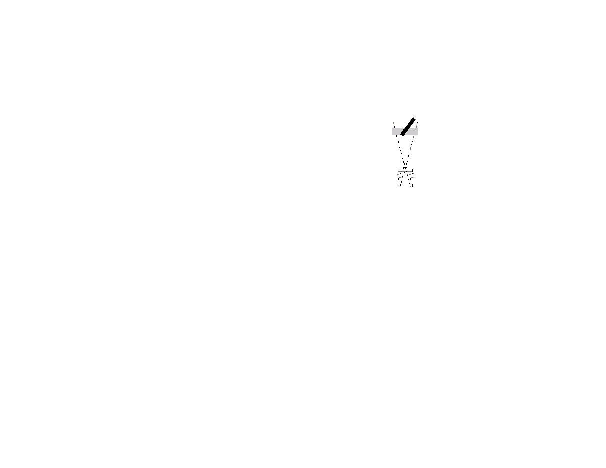
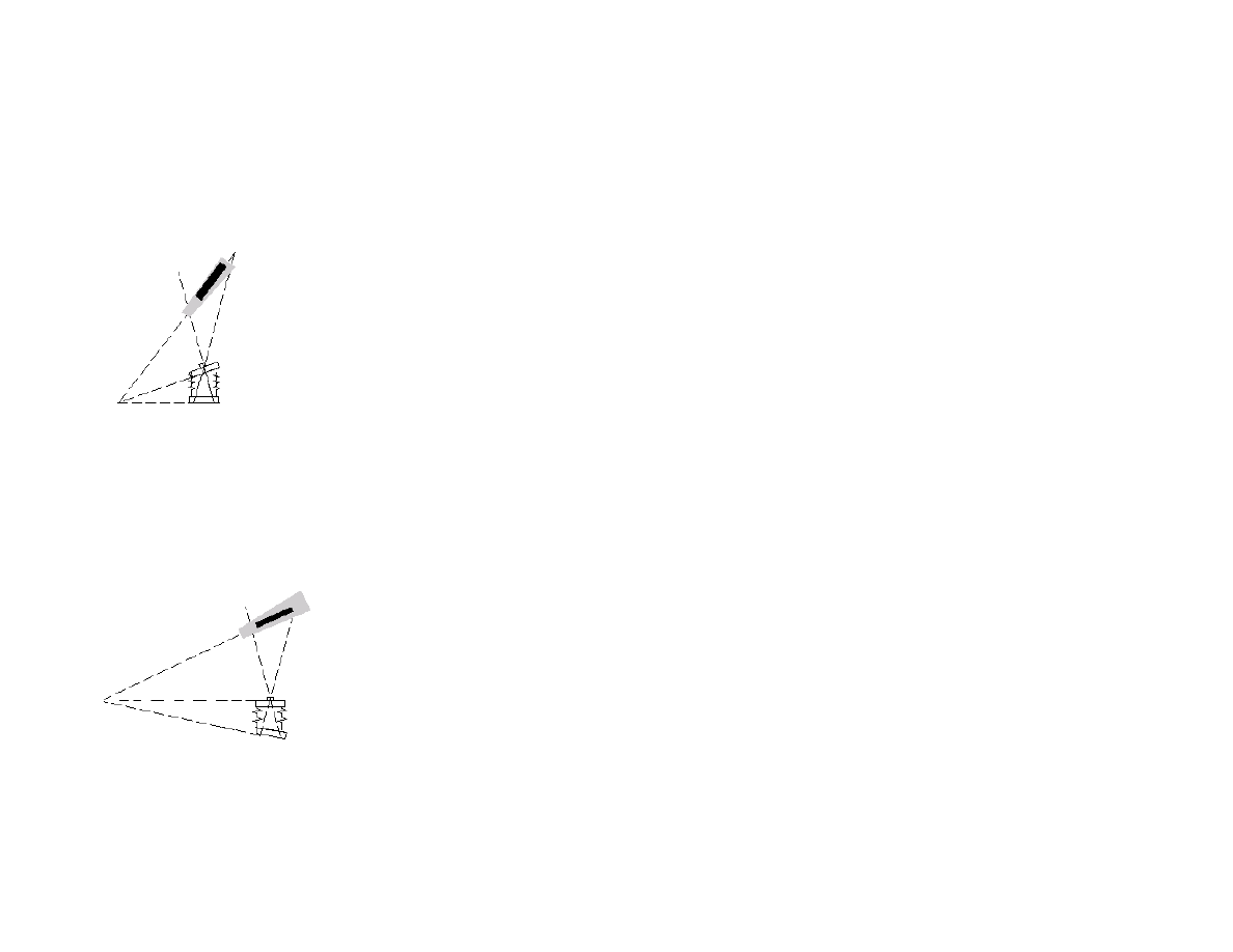
The Scheimpflug Rule
The principles behind camera movements and depth of
field are summarized in the Scheimpflug rule (named
after Theodor Scheimpflug, an Austrian army captain
with an interest in photogrammetry). The rule states
that a subject will be rendered with the greatest
sharpness when the extended lines drawn from the
subject plane, the film plane and the lens plane all meet
(intersect) at one point. (See the above figures.)

39
8.6 Developing Sheet Film
Color film (positive or negative) should be processed
by a lab. You give the lab the film in a light proof box.
Ask the lab to give you the box back. Light proof boxes
are useful.
You may process your black and white film yourself –
in a tank, a drum or in trays. I suggest you start with
trays.
Develop only one or two sheets at a time until you get
some experience. With practice you may process six 4
x 5 in. sheets at a time. For 4 x 5 in. film use 8 x 10 in.
trays. Use gloves to avoid skin contact with the
chemicals.
Lay out three trays—one for the developer, one for the
stop bath, one for the fixer. In addition you need one
pre-soak tray for each sheet of film. Put the sheets in
the pre-soak trays with the emulsion side up to make
sure there are no bubbles on the film’s surface.
When you move the sheet of film into the developer,
the emulsion side should be down. As you put each
sheet of film in the developer, it should be swished
back and forth to avoid air bubbles sticking to the
emulsion. Slide another sheet of film into the developer
tray and repeat the same procedure. Be careful so you
do not scratch the emulsion. The same procedure is
repeated for a third sheet of film, if you are developing
that many sheets at a time.
You agitate the film sheets by taking the bottom sheet,
freeing it from the pile and placing it on top of the
stack. This is a slow and continuous process. You
should turn the entire stack four times every minute.
You should also rotate the stack 90 degrees every two
minutes so that the film is pulled in different directions.
When the timer buzzes, you move the film, sheet by
sheet, into the stop bath. Swish the sheets gently so that
the entire emulsion quickly comes into contact with the
acetic acid. Agitate the stack of film the same way as
you did during development. The film sheets are then
moved into the fixer and agitated. When the fixing time
is up, you turn on the lights.
The sheets may be washed in a tray of running water
and are then given a rinse in a very weak dilution of a
wetting agent (Photo-Flo or other). You then hang the
negatives to dry in a dust-free place. The developer and
stop bath are normally dumped. The fixer can be used
again.
Film sheets may also be processed in a drum, e.g. Jobo
Multitank 2521. For tank development, see Steve
Simmons 1987.
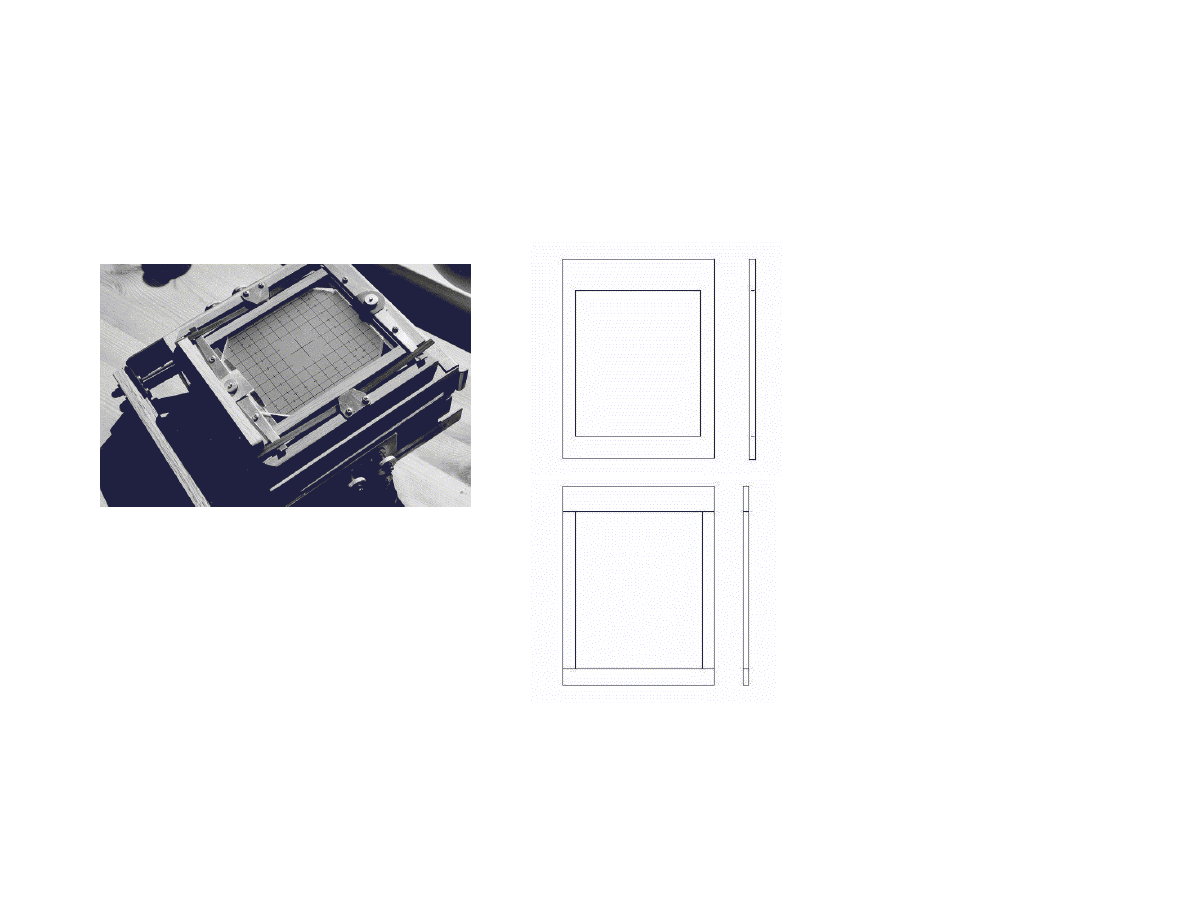
40
Addendum: A more elaborate
ground glass frame
The ground glass frame in the first edition of my book
Building a Large Format Camera (1996) is fairly
simple (see above 4.3 and Figures 18 and 19). The
following is my most recent design of a ground glass
frame. Both designs work well. My latest design,
however, is more elegant and makes it easy to add or
remove a fresnel lens in the field. This ground glass
frame is thinner than in my first design (approx. 10–11
mm).
Figure I (top right): The ground glass frame is made
of 4 mm birch plywood and a frame of 5 or 6 mm
hardwood strip. The external dimensions of the ground
glass frame are approx. 120 x 160 mm. A rectangular
window (cutout) is made in the piece of plywood
(approx. 101 x 121 mm). The width of the window
should be the same as the width of the ground glass.
Figure II (above): Pieces of 5 or 6 mm hardwood strip
are cut to form a frame which is glued on top of the
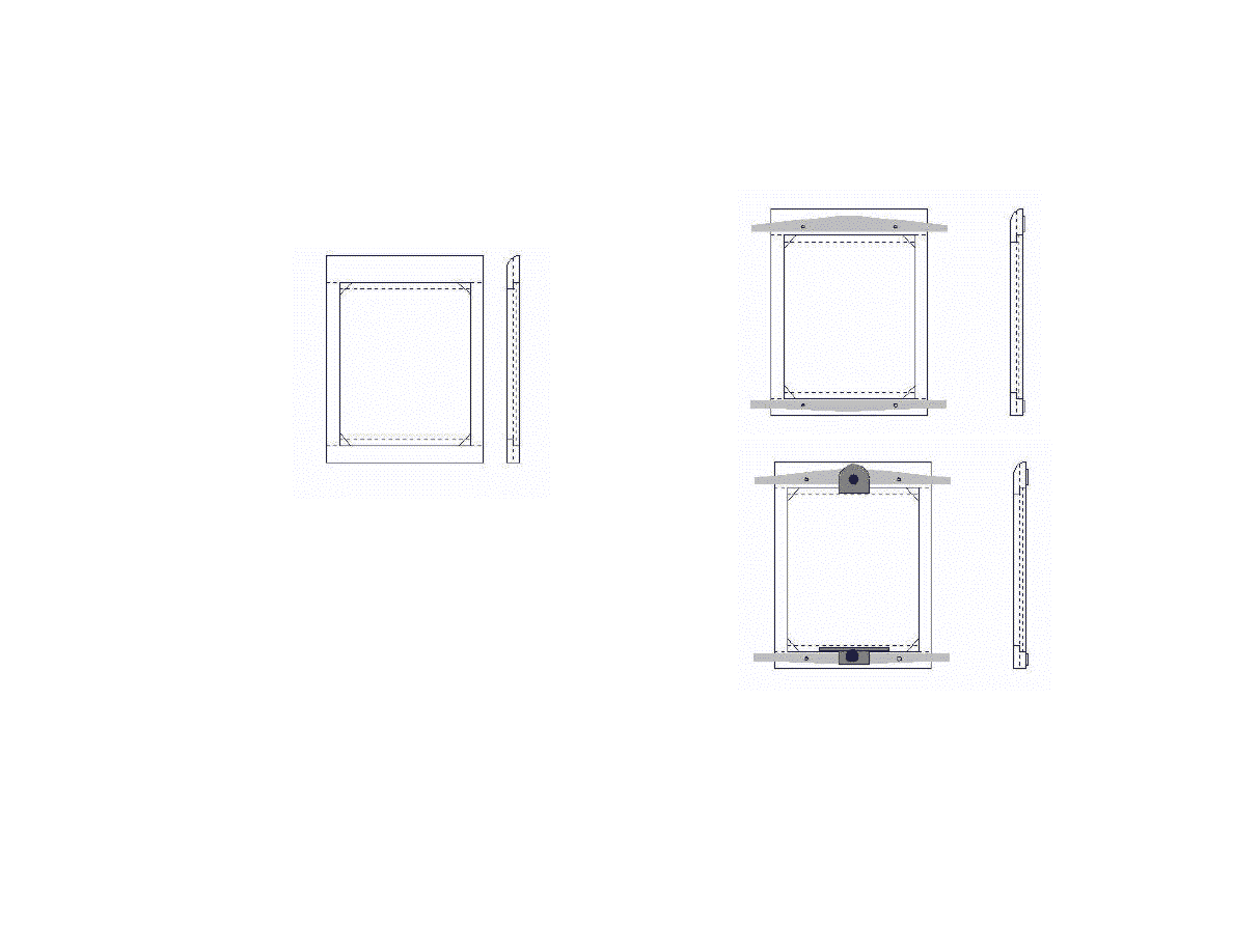
41
birch plywood. The top piece is about 20 mm wide and
the bott
om
piece13 mm wide. When they are glued to
the plywood there will be a 5 mm ledge for the ground
glass.
Figure III (above): When the ground glass eventually
is installed two pieces of 0.8 mm brass shim are placed
between the birch plywood and the ground glass so that
the focusing surface of the ground glass is 4.8 mm from
the bottom surface of the ground glass frame. The
ANSI standard has a plus minus tolerance of 0.18 mm.
Use a pair of Vernier calipers or a micrometer to check
the measurements.
Figure IV (top right): The grey strips in the figure are
made from 1.5 or 2 mm brass. The strips will
eventually go under the leaf springs which keep the
ground glass frame in place in the film holder seat.
Three holes are drilled in the brass strips, two for the
screws attaching the strips to the ground glass holder,
the third in the middle for the retaining mechanism
which holds the ground glass in place.
Figure V (above): The mechanism which holds the
ground glass in place is made of 1 mm brass. (See
Figure VI.) A hole is drilled in both
pieces. There will
be a screw from underneath the ground glass frame
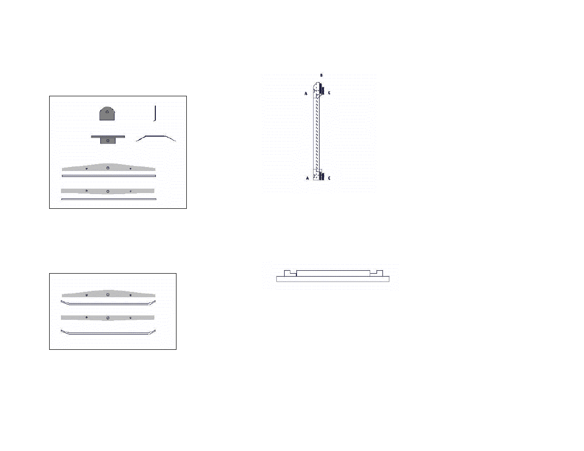
42
which goes through the hole. A thumb nut, the black
disk in the drawing, is used for fastening.
Figure VI : The drawing shows the pieces of brass
from above and in profile. The bottom piece is bent to
form a spring which exerts a certain pressure on the
ground glass. The top piece is bent about 60–70
degrees.
Figure VII: The ends of the brass strips are bent
upwards to keep the leaf spring in place.
Figure VIII: The brass strips (B) and the ground glass
retaining mechanism are held in place by screws (A)
from underneath the ground glass frame. Knurled nuts
(thumb nuts) (C) are used for fastening.
Figure IX: Top view of the camera back with film
holder seat and ground glass frame. Leaf springs and
retainers for leaf springs not shown. The film holder
seat may be made
of 6 x 20 mm hardwood strip with 6
x 10 mm hardwood strip glued on top to form a rabbet
approx. 6 x 10 mm for the leaf springs.
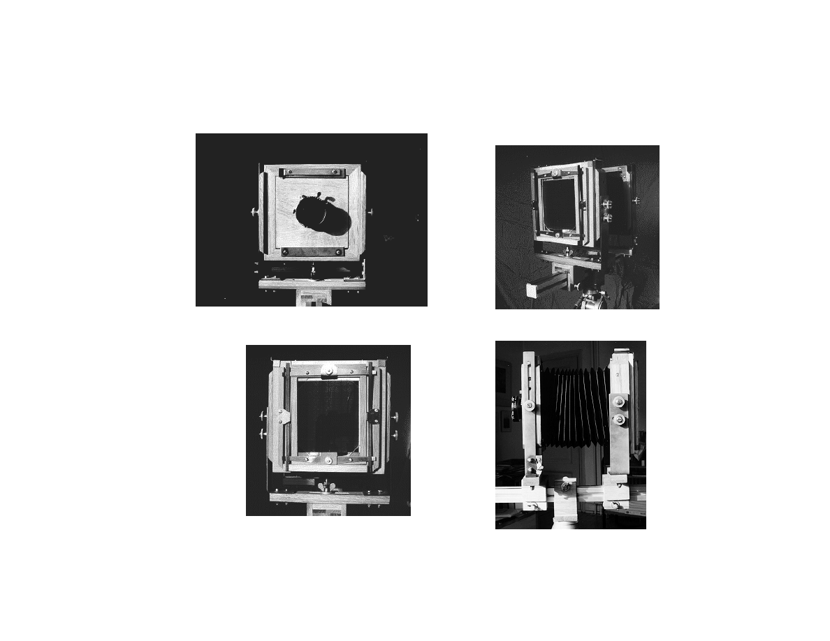
43
Pictures of the Camera
Front, rear and side view of the camera.
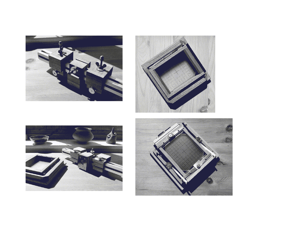
44
The optical bench viewed from above and from below.
Right: The two ground glass frame designs. In the second picture
a film holder is inserted in the spring back.
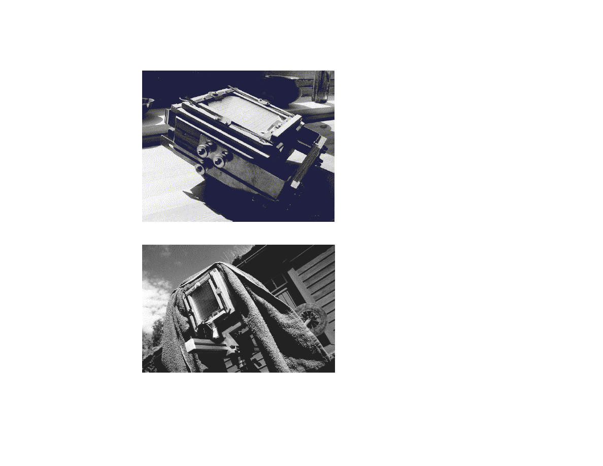
45
Left: The camera folded is about 25 x 25 x 10 cm.
Below: A picture of the back of my 4 x 5 in. camera. A blue towel
served as a focusing cloth on this hot summer day in the western
part of Norway. A loupe case resting on the monorail. The
picture was taken while I was testing a new springback.
Larger versions of these pictures are found at my web site:
http://home.online.no/~gjon/jgcam.htm.

46
Literature and References
Adams, Ansel. The Camera. 11th printing. Boston–Toronto–
London: Little, Brown and Company, 1991. 210 pages.
ISBN 0-8212-1092-0.
Alt, Patrick. "Refurbishing View Cameras." View Camera,
March/April 1995. Sacrameento, CA.
Altenbernd, Nicholas. "Budget Large Format. A Do-It-
Yourself Enlarger Project." Camera and Darkroom, January
1993, pp. 12–16. N. Hollywood, CA. (Enlarger back for 4 x
5 Bender camera.)
Blaker, Alfred A. "Applied Depth of Field". Camera and
Darkroom Photography, March–September 1991. N.
Hollywood, CA.
Camera Making. Elstree, Herts: Oldtimer Cameras Ltd.,
1996. 226 pages. (Amateur Photographer Articles on
camera and bellows making 1887–1995.) Oldtimer Cameras
Ltd., P. O. Box 28, Elstree, Herts WD6 4SY, England.
Davis, Dennis. "Wooden Cameras from the United
Kingdom." View Camera, May–June 1991, pp. 53–58.
Sacrameento, CA. (The Lisjon camera kit (no longer
availbale), the Nesbitt and Walker cameras.)
Englander, Joe. "ReadyLoad, QuickLoad, Shoot. A
Comparison of 4x5 Film Holders." Camera and Darkroom,
April 1995, pp. 52–57. (Comparison of film holder depths.)
Fader Photo Works. Porta Vu II. 4 x 5 View Camera Kit.
Assembly Instructions. Ann Arbor, Mich: Fader Photo
Works, n.d. 8 pp.
Foto for alle. Populær Mekanik, 1, 1951. København
(Copenhagen): Forlaget P.M., 1951. 96 pages.
Fuller, Tom. "Five–Seven. The forgotten format revisited."
Camera and Darkroom , January 1994, pp. 52–58. N.
Hollywood, CA. (Information on 5x7 step-up adapter for
4x5 field cameras.)
Fuller, Tom. "The Bender 4x5 View Camera Kit." Camera
and Darkroom Photography, June 1991, pp. 25–27. Beverly
Hills, CA.
Gutierrez, Al. "Build a View Camera." Popular Science Do-
It-Yourself Yearbook 1992. pp. 111–118. ISBN 0-696-
11111-X.
Hasluck, Paul N. The Book of Photography—Practical,
Theoretic and Applied. London–Paris–New York &
Melbourne: Cassell And Company, 1907. (The chapter
"Miscellaneous Items" has instructions for making square
and tapered bellows.)
Helm, Peter. Selbstbau einer Grossformat-Fachkamera.
Titz-Gevelsdorf: Verlag Peter Helm, 1989. 6th edition. 84
pages. ISBN 3-88673-000-X. (Instructions for making a
simple monorail camera of metal.)
Håkansson, Patrik and Lundell, Kurt. "Bygg din egen
storformatskamera." Aktuell fotografi 7–8, 1988, pp. 64–68.
Stockholm 1988. Also see correction in Aktuell fotografi 9,
1988.

47
Höglund, Arne. "Förstorad förstoringsapparat." Foto, July–
August 1987, pp. 68–69. Stockholm 1987. (Sketches for a
DIY 4 x 5 inch enlarger.)
Johnson, Evan P. "A Brake for Your Dolly." Photography
Handbook. A Fawcett Book 106. Greenwich, CT: Fawcett
Publications, 1950. pp. 90–91, 138. (Plans for a wooden
tripod dolly with brakes.)
Layton, John. "Designing and building your own camera,"
View Camera, March–April 1995, pp. 38–44. Sacramento,
CA.
Layton, John. "Build your own 4 x 5 field-view camera,"
View Camera, November–December 1996, pp.48–56.
Sacrameento, CA.
Michelsen, Jim. "Stabilt fotostativ." Teknikk og hobby, okt.
1955. pp. 74–75. Oslo: Nasjonalforlaget 1955. (Plans for
wooden tripod.)
Mönks, Thomas. Grossformatkamera selbst gebaut.
Stuttgart: Lindemanns Verlag, 1991. (Third edition)
Newlands, Gerald. "Think Big. A do-it-yourself slide-copier
project." Camera and Darkroom, June 1993, pp. 14–15. N.
Hollywood, CA.
Ott, Joseph. "Universal Enlarger." Popular Mechanics.
Chicago: Popular Mechanics Company, 1942. pp. 118–121.
Partridge, Graham. 5 x 4 Camera. Henly-on-Thames 1992.
35 pages. (Plans for a rigid baseboard, non-collapsible,
flatbed camera. Also plans for a tapered bellows.)
Photography with large format cameras. Kodak Publication
O–18. Rochester: Eastman Kodak Company, 1988. 96
pages. ISBN 0-87985-476-6.
Rittsel, Pär. "Ett välpussat bygge för stora bilder." Foto,
October 1980, pp. 20–21. Stockholm, 1980. (About the
Lester Fader camera kit.)
Robinson, Mike. "How to build a camera bellows." View
Camera, July–August 1996, pp.52–54. Sacrameento, CA.
Romney, Edward H. Bellows Making Text. Drayton, SC,
1977 and 1990. 14 pages.
Romney, Ed and James Tannehill. Build a view camera. 23
pages. Drayton, SC, 1979. ISBN 1-886996-63-6. (Plans for
easily built 2 x 3 metal view camera, expandable to 4 x 5.
Romney, Ed. Build a wooden plate camera. 15 pages.
Drayton, SC, 1995. (Reprint of anonymous encyclopedia
article. 73 scale drawings of a typical 3x4 or 4x5 camera
such as Sinclair Una, Cycle Graphic or Century.)
Spreadbury, S. "Into View. A Home-Made 4 x 5in Camera."
Amateur Photographer, 13 March 1982.
pp. 127–128.
Simmons, Steve. Using the View Camera. 2nd edition. New
York: Amphoto, 1987. 144 pages. ISBN 0-8174-6347-X.
Revised edition 1992. (Excellent introduction to large
format photography.)
Sittenauer, Herbert. "Alptraum Grossformat." Fotomagazin
4/94. pp. 74-76.

48
Smith, Arthur H. "Spring Back for your Camera."
Photography Handbook. A Fawcett Book 106. Greenwich,
CT: Fawcett Publications, 1950. pp. 101–103.
Stone, Jim. A User's Guide to the View Camera. Boston:
Little Brown and Company, 1987. 192 pages.
Stroebel, Leslie D. View Camera Technique. 5th edition.
New York–Boston–London: Focal Press 1986. 310 pages.
ISBN 0-240-51711-3. 6th edtion 1993, 320 pages. ISBN: 0-
240-80158X . (The classic reference work on large format
photography.)
Stroebel, Leslie D. View Camera Basics. Boston–Oxford–
Melbourne: Focal Press, 1995. 162 pages.
ISBN 0-240-80220-9.
Tomosy, Thomas. Restoring Classic & Collectible Cameras.
Buffalo, NY: Amherst Media, 1998. 176 pages. ISBN 0-
936262-59-1. (Instructions on bellows making etc.)
Wernersson, Mats. "Vi bygger en storformatskamera for
2 200 kr." Foto, 11/1996, pp. 58–59. Helsingborg, 1996.
(About the Bender kit.)
West, Bert. Build your own view camera. Highland Park, IL:
Dogstar Publishing, 1995. 112 pages. ISBN 1-886757-07-0.
(Useful instructions for making pleated bellows.)
"Wooden Camera Wrap-up." View Camera, November–
December 1994, pp. 32–37. Sacrameento, CA.
(Round table discussion with leading US wooden field
camera manufacturers.)
Zeichner, Robert A. "How to Align your Ground Glass."
View Camera, November–December 1996. pp 57–59.
Sacrameento, CA.
Internet sources:
Archive of the International Society of Handbuilt Cameras.
http://www.mail-archive.com/cameramakers@ilist.net/
Bardell, Doug. Field Cameras.
http://www.cyberbeach.net/~dbardell/
Bardell, Doug. How to make bellows.
http://www.cyberbeach.net/~dbardell/
eBay: http://www.ebay.com/
Online auction site. (Used lenses, cameras, camera parts,
bellows etc.)
Grepstad, Jon. View Camera Construction FAQ.
http://home.online.no/~gjon/
Grepstad, Jon. Depth of Field and Other Technical
Information. http://home.online.no/~gjon/
Grepstad, Jon. Photographic Lenses—Some Books, Articles
and Online Information. http://home.online.no/~gjon/
Gudzinowicz, Michael. Large-Format Lens Specifications.
http://www.graflex.org/lenses/lens-spec.html
International Society of Handbuilt Cameras.
http://www.cnsp.com/mdesign/handbuil.htm
Micro-Tools, http://www.micro-tools.com/

49
Camera repair/restoration tools, vernier calipers,
micrometers etc.
Mittelmann, Rudolf. Large Format Photography. (Plans).
http://www.geocities.com/SoHo/Suite/7013/foto/index.html
Mottweiler, Kurt. Bellows Design.
http://www.cnsp.com/mdesign/links.htm
Quang-Tuan Luong. Large Format Photography.
http://www.cs.berkeley.edu/~qtluong/photography/lf/index.h
tml
Technical Books on Photography by Harald M. Merklinger.
http://Fox.nstn.ca:80/~hmmerk/ (Articles, diagrams and
.mov-files about depth of field, the Scheimpflug rule, and
the "Hinge rule".)
Vail, James. View Camera Construction Plans.
http://www.srv.net/~vail/
History of Camera Design – Some Sources
Coe, Brian. Cameras. From Daguerrotypes to Instant
Pictures. Gothenburg: Nordbok, 1978. 240 pages. (One of
the best sources on the subject.)
Gernsheim, Helmut and Alison. The History of Photography
from the Camera Obscura to the Beginning of the Modern
Era. New York: McGraw-Hill,1969. 599 pages.
Lothrop, Eaton S. A Century of Cameras from the Collection
of the International Museum of Photography at George
Eastman House. Dobbs Ferry, New York: Morgan &
Morgan, 1973. 150 pages. ISBN 0-87100-044-x.
Pizzighelli, G. Anleitung zur Photographie für Anfänger.
Druck und Verlag von Wilhelm Knapp, 1887. Facsimile
Lindemanns Verlag, Stuttgart 1992. 160 pages. ISBN 3-
928126-40-7.
Smith, R.C. Antique Cameras. London and Vancouver:
David & Charles 1975.
Stroebel, Leslie D. View Camera Technique. 5th edition.
New York–Boston–London: Focal Press, 1986. 310 pages.
ISBN 0-240-51711-3.
Talén, C.W. Amatørfotografen. Kristiania (Oslo): Steen’ske
Bogtrykkeri og Forlag, 1901. (Third edition). 282 pages.
Willsberger, Johann. Fotofaszination—Kameras, Bilder,
Fotografen. Bertelsmann Lexikon-Verlag: Gütersloh–
Berlin–München–Wien, 1975. Danish edition.
Kamerakavalkade gennem 150 år. ISBN 87-15-08232-6.
Addresses (US, UK and Scandinavian)
American Science & Surplus, 3605 Howard Street, Skokie,
IL 60076. Phone (708) 982-0870. Fax (800) 934-0722.
(Ground glass and other items. Mail order.)
Andrews Cameras, 16 Broad Street, Teddington,
Middlesex, TW11 8RF, United Kingdom.
Phone (0181) 977 1064. Fax (0181) 977 4716. (Used lenses
and other equipment.)
Beattie Systems, Inc., 2407 Guthrie Ave., Cleveland, TN
37311. Phone 800-251-6333 or 423-479-8566.
http://www.beattiesystems.com/index.html
(Beattie intenscreens.)

50
Bender Photographic, 19691D Beaver Valley Road,
Leavenworth, WA 98826. Phone (800)776-3199 or
(509)763-2626. Fax (509)763-1043.
http://www.benderphoto.com/ (The Bender kit.)
W.M. Berg, 499 Ocean Avenue, East Rockaway, NY 11518.
Phone (516) 596 1700. Fax (516) 599 3274.
http://www.wmberg.com/ (Thumbs screws, knurled thumb
nuts, threaded inserts, gears etc. B 97 is their master catalog.
M 92 a catalog of metric parts and components.)
Calumet Photographic, 890 Supreme Dr., Bensenville, IL
60106. Phone 1-800-225-8638 (1-800-CALUMET).
http://www.calumetphoto.com/ (Standard Cambo bellows.)
Camera Bellows Ltd., Unit 3-5, St Pauls Road, Balsall
Heath, Birmingham B12 8NG, United Kingdom. Phone
(0121) 440 1695. Fax (0121) 440 0972. (Custom made
bellows.)
Darkroom Aids Co., 3449 N. Lincoln Ave., Chicago, IL
60657. Phone (312) 248-4301.(Bellows cloth.)
Edmund Scientific, 101 East Gloucester Pike, Barrington,
NJ 08007-1380. Phone (609) 573-6879. Fax (609) 573-1379
(orders). International Department: Phone (609) 573-6879.
Fax (609) 573-6882. http://www.edmundscientific.com/
(Annual Refence Catalog, Hobbyist Edition, and
Industrial/Educational Catalog.)
Galupki, Jürgen. Schärfentiefe. A Quick Basic depth-of-field
calculator for MS-DOS. German text. Foto online
http://www.fotoline.ch/wissen/formtab/s-tiefe.htm
S.K. Grimes, 153 Hamlet Ave., P.O. Box 1724,
Woonsocket, RI 02895. http://www.skgrimes.com/
Email: skgrimes@skgrimes.com. Phone 401-762-0857.
Fax 401-762-0847. (Services for large format
photographers, mounting of barrel lenses in shutters,
cleaning of shutters, new shutters, adapters etc.).
Kozik Cameratechniek, Oude Sluis 6, 3111 Pk Schiedam,
The Netherlands. Phone (010) 4703661. Fax (010) 4703661
(The Kozik kit, custom made bellows, used lenses.)
Oldtimer Cameras Ltd., P. O. Box 28, Elstree, Herts WD6
4SY, England. Phone (0181) 953 5479 or 953 2263. Fax
(0181) 905 1705. Email: oldtimercameras@mcmail.com
Graham Partridge, 28 Bradley Road, Nuffield, Henley-on-
Thames RG9 5SG. Phone (0491) 641155.
(Plans for 4 x 5 rigid baseboard camera.)
Photo-Graphic Systems, 412 Central S.E. Alburquerque,
NM 87102. Phone (505) 247-9780. Fax (505) 243-4407.
http://www.pgsys.com/ (Used lenses and other equipment.)
Prokom ab, P.O. Box 430, 35106 Växjö, Sweden. Phone
(070) 730 55 00. (Used lens and other equipment.)
Romney Publishing, P. O. Box 487, Drayton SC 29333.
Phone (864) 597 1882. http://www.edromney.com/
(Bellows making text, plans for 2 x 3 metal camera, etc.)
Jonathan M. Sachs, 12 Ash Street, Cambridge, MA 02138.
(Depth of field, a freeware depth of field calculator for
Windows.) http://www.dl-c.com/dl.html

51
Schönherrs foto, Upplandsgatan 16, P.O. Box 45126, 10430
Stockholm, Sweden. Phone (08) 32 76 47.
http://www.schoenherrsfoto.se/ (Used lenses.)
Shutterbug, Patch Publishing, 5211 S. Washington Ave.,
Titusville, FL 32780. http://www.shutterbug.net/ (Magazine,
ads for second hand lenses etc.)
Stephen Shuart – "Large Format Specialist", PO Box 419,
Kane, PA 16735-0419, Phone (814) 837-7786. Fax (814)
837-2248. E-mail: shuart@penn.com.
http://www.stephenshuart.com/
(Ground glass, used lenses and camera parts.)
M.R. Warner & Son Ltd., 22-26 Chapel Ash,
Wolverhampton, W. Midlands WV3 OTS, United Kingdom.
Phone (01902) 455255. (Used lenses and other equipment.)
Tandy Leather Company, P.O. Box 791, Fort Worth, TX
76101. http://www.tandyleather.com/index.html
(Leather for bellows. Have stores in most states in the US.)
View Camera, Steve Simmons Inc. , 1400 S St.,
Sacramento, CA 95814. E-mail: largformat@aol.com
http://www.viewcamera.com/ (Magazine)
Western Bellows Company, 9340 7th St., Suite G, Rancho
Cucamonga, CA 91730-5664. Phone (909) 980-0606.
Large Format Cameras and Lenses (US addresses
mainly)
Arca Swiss Inc.: 442 W. Belden Street,
Chicago, IL 60614-3816. Phone: 773 248-2513.
Fax 773 248-2774 (Arca-Swiss, Phototechnik AG, CH-8810
Horegn, Switzerland. Phone (1) 725 61 60. Fax (1) 725 64
37.)
Ballester: Manufacturas Ballester, Monaco No. 291, Col.
Zacahuitzco, Mexico 03550 D.F.
Phone (011) 525-674-4929. Fax (011) 525-672-2499.
Caltar: Calumet Photographic, 890 Supreme Dr.,
Bensenville, IL 60106. Phone: 1-800-225-8638 (1-800-
CALUMET).
Cambo: Calumet Photographic, 890 Supreme Dr.,
Bensenville, IL 60106. Phone: 1-800-225-8638 (1-800-
CALUMET). Or: Cambo Fotografische Industrie B.V.,
Postbus 200, 8260 AE Kampen, The Netherlands. Phone:
(038) 3314644. Fax: (038) 3315110.
Canham Large-Format Cameras: 2038 E. Downing, Mesa,
AZ 85213. Phone (602) 964-8624.
Ebony: Ebony Co., Ltd., Shin Oyama Building 1st Fl., 38-12
Oyama Kanai-cho, Itabashi-ku, Tokyo 173, Japan, Phone:
+81-3-39723170. Fax: +81-3-59953738. E-mail:
hiromi@ebonycamera.com. Or: Robert White, Unit 4 Alder
Hills Industrial Estate, 16 Alder Hills, Poole, Dorset BH12
4AR, Phone: +44 1202 723046. Fax +44 1202 737428. E-
mail: sales@robertwhite.co.uk
Fatif: Fatif S.r.l., Via Maniago, 12 - 20134 Milano, Italy.
Phone +(39) (0)2-2157843. Fax +(39) (0)2-2153151
Gandolfi Ltd.: 24 Focus 303, South Way, Andover, Hants
SP10 5 NY, United Kingdom. Phone (0264) 35 78 59.

52
Gowland: Peter Gowland, 609 Hightree Road, Santa
Monica, CA 90402. Phone (310) 454-7867.
GranView: 2050 Executive Drive, Palm Springs, CA 92262.
Phone (760) 323-9575. Fax (760) 323-9644
Hoffman Camera Corp.: 19 Grand Ave., Farmingdale, NY
11735. Phone (516) 694-4470.
Horseman Creative: P.O. Box 440028, St. Louis, MO
63144. Phone (800) 501-6866. Fax (800) 501-6867.
Inka: Inka Instruments Factory, Kampen b.v., P.O. Box 52,
8260 AB Kampen, The Netherlands. Phone (5202) 11932.
Fax (5202) 260478.
Kirby Camera: Rayment Kirby, Coggers Farm, Horam,
Heathfield, East Sussex TN21 OLF, United Kingdom.
Phone (04353) 2148.
Kozik: Kozik Cameratechniek, Oude Sluis 6, 3111 Pk
Schiedam, The Netherlands. Phone (010) 4703661. Fax
(010) 4703661.
Linhof: HP Marketing Corp., 16 Chapin Rd., Pine Brook,
NJ 07058. Phone (201) 808 9010. Linhof Präzisions-
Kamera-Werke GMBH, P.O. Box 701229 D-8000 Munich
70. Phone (089) 72492-0. Fax (089) 72492250.
Lotus View Camera: viewcamera@weisserlotus.co.at
http://www.lotusviewcamera.at/
Nagaoka: The Lens and Repro Equipment Corp., 33 West
17th St., New York, NY 10011. Phone (212) 675-1900.
Nikon Inc.: 1300 Walt Whitman Rd., Melville, NY 11747.
Phone (516) 547-4200.
Osaka: Bromwell Marketing, 3 Allegheny Center, #111,
Pittsburgh, PA 15212-5319. Phone (412) 321-4118.
Phillips: Phillips & Sons, P.O. Box 1281 Midland, MI
48641-1281. Phone/Fax (517) 835 7897.
Rodenstock: HP Marketing Corp., 16 Chapin Rd., Pine
Brook NJ 07058. Phone (201) 808-9010.
Schneider Corp.: 400 Crossways Park Dr., Rochester, NY
14624. Phone (516) 496-8500.
Sinar: SinarBron Imaging, 17 Progress Street, Edison, NJ
08820. Phone (908) 754-5800. Fax (908) 754-5807. (Sinar
AG, Shaffhausen, CH-8245 Feuerthalen, Switzerland. Phone
(053) 293535. Fax (053) 293578.)
Toho: Toho Machine Co, 20-11 Naka-Jujo 3-Chome,
Kita-Ku, Tokyo 114, Japan. Phone 81-33-908-0320
Fax 81-33-908-0522.
Toyo-View: Mamiya America Corporation, 8 Westchester
Plaza, Elmsford, NY 10523. Phone (914) 347-3300. Fax
(914) 347-3309.
Walker: Calumet Photographic, 890 Supreme Dr.,
Bensenville, IL 60106. Phone: 1-800-225-8638 (1-800-
CALUMET). Robert White, Unit 4 Alder Hills Ind Est,
16 Alder Hills, Poole, Dorset, BH12 4AR,
United Kingdom, Phone +44 (0)1202 723046,
Fax +44 (0)1202 737428

53
Wisner Classic Manufacturing co. Inc.: P.O. Box 21,
Marion, MA 02738. Phone (508) 748-0975.
Wista: Fields and Views Inc., P.O. Box 132, Old Chatham,
NY 12136. Phone (212) 779-1471.
Zone VI: Calumet Photographic, 890 Supreme Dr.,
Bensenville, IL 60106. Phone: 1-800-225-8638 (1-800-
CALUMET).
Conversion Table
1 mm = 0.039370 inch
1 inch = 25.400 mm
inch
mm
1
25.400
2 50.800
3 76.200
4 101.600
5 127.000
6 152.400
7 177.800
8 203.200
9 228.600
10 254.000
11 279.400
12 303.800
½ 12.700
¼ 6.3500
¾ 19.0500
1/8 3.1750
3/8 9.5250
5/8 15.8750
7/8 22.2250
1/16 1.58750
3/16 4.76250
5/16 7.93750
7/16 11.11250
9/16 14.28750
11/16 17.46250
13/16 20.63750
15/16 23.81250
1/32 0.79375
2/32 2.38125
5/32 3.96875
7/32 5.55625
9/32 7.14375
11/32 8.73125
13/32 10.31875
15/32 11.90625
17/32 13.49375
19/32 15.08125
21/32 16.66875
23/32 18.25625
25/32 19.84375
27/32 21.43125
29/32 23.01875
31/32 24.60625
Conversion software
(freeware) can be
downloaded from:
http://home.online.no/
~gjon/depth.htm
About the
Author
I was born in
Norway in 1944 and
have lived nearly all my life here.
I studied English, French and literary theory at the
University of Bergen in Norway, and also spent a year in the
US as a foreign student at Wesleyan
Photograph: Eli Berge University,
Middletown,
Connecticut, studying English and American literature, and
Italian and Latin.

54
As a young boy and teenager I was fascinated by
woodworking and mechanics. I remember I admired my
grandfather, who owned a small farm and who died when
my mother was only five years old, for building an organ
from a kit. I also admired one of my uncles, an arts and craft
teacher, who built a beautiful fishing rod from bamboo and
hickory. From the age of eleven I used to read regularly the
Norwegian edition of Mechanix Illustrated. When I was in
my early teens I built a camera tripod based on an article in
that magazine. Thirty years later I built a similar tripod using
materials which were not available to me in my boyhood.
I developed an interest in visual form and photography when
I was a young boy, but photography was pretty expensive
when I grew up. My father, who was a teacher in a
countryside community, had a Kodak Brownie E. My own
first camera was a 35 mm Dacora Dignette with a Steinheil
Cassar lens, which my parents bought me second hand in
1959. It cost NOK 150, which was quite a lot of money at
the time. The camera served me well for years and I still
have it.
I started working more seriously on photography in the late
1980s. In 1991 my interests turned to large format
photography and I built my first large format camera. In
1996 I wrote the first version of Building a Large Format
Camera, which has been bought by ardent amateur
photographers and woodworkers in North and South
America, Europe, Australia, Asia and Africa. I updated and
revised the book in December 1999. Since 1990 I have also
been doing a lot of pinhole photography. My article
"Pinhole Photography—History, Images, Cameras,
Formulas", written in 1996, is available at web servers in
Europe, the US and Australia and was reviewed by the
international photo magazine Zoom in their November–
December 1999 issue.
I am currently an adviser and head of information at the
Norwegian Language Council, an agency under the
Norwegian Ministry of Cultural Affairs.
In my spare time I enjoy reading—my interests range from
philosophy and the social sciences to poetry. I enjoy
listening to jazz and classical music, spending time on the
Internet and outdoors—and doing photography or
woodworking. My main interest in photography is
landscapes. I lead a quiet and simple life and do not usually
write articles like this about myself.
Wyszukiwarka
Podobne podstrony:
Eurocode 2 Part 1 1 2004 NA UK Design of concrete structures General rules and rules for buildin
Applications and opportunities for ultrasound assisted extraction in the food industry — A review
Law and Practice for Architects
2 grammar and vocabulary for cambridge advanced and proficiency QBWN766O56WP232YJRJWVCMXBEH2RFEASQ2H
Caliber and?atures?tails for Seiko Sports Stopwatches
Control and Instrumentation Engineer?scription
Free Energy Bedini Device And Method For Pulse Charging A Battery Patent Info 2004
CCI Job Interview Workbook 20 w PassItOn and Not For Group Use
Types of A V Aids and relevance for LT
Caliber and?atures?tails for Seiko Quartz Hybrid Watches
Student Roles and Responsibilities for the Masters of Counsel
Caliber and?atures?tails for Seiko Quartz Kinetic Watches
Prospects and challenges for Arctic Oil Development
Caliber and?atures?tails for Seiko Perpetual?lendar Watches
Applications and opportunities for ultrasound assisted extraction in the food industry — A review
Law and Practice for Architects
2 grammar and vocabulary for cambridge advanced and proficiency QBWN766O56WP232YJRJWVCMXBEH2RFEASQ2H
więcej podobnych podstron