
2009 ACCESSORIES & EQUIPMENT
Power Sliding Door - Service Information - Grand Caravan, Town & Country
DESCRIPTION
DESCRIPTION
Some vehicles are equipped with a power sliding door system. The components of the power sliding door
system are:
Power sliding door drive assembly
Power Sliding Door Control Module (PSDM)
Totally Integrated Power Module (TIPM)
ElectroMechanical Instrument Cluster (EMIC) (also known as the Cab Compartment Node/CCN)
Read Door Control Modules (RDCM)
Wireless Ignition Node (WIN)
Next Generation Controller (NGC)
Sliding door wire harness and chain link track (Contains the wiring harness that connects the door
electrical to the body electrical)
Controller Area Network (CAN) data bus
B-pillar switches
Overhead console switches
Key fob switches
Power sliding door cinching latches (includes the latch ratchet primary (ajar) switch, sector gear switch,
pawl switch, handle switch and cinch/release motor)
Each power sliding door is equipped with a power sliding door drive assembly with PSDM. The drive assembly
is mounted to the body in the lower sliding door sill area with the use of five retaining nuts. The PSDM is
mounted directly to the inboard side of the drive assembly with two retaining screws. The power sliding door
motor is also located on the inboard side of the drive assembly. Unlike the PSDM which can be serviced
separately, the motor is not available as a service item and must be replaced with the drive assembly should it
become damaged or inoperative. The wire harness and chain link track and the power sliding door drive
assembly are visible with the door open in the lower door sill area.
The cinching latch assembly is located in the rear of the power sliding door, near the body line. The latch has
integral components (latch ratchet primary (ajar) switch, sector gear switch pawl switch, handle switch and
cinch/release motor) that are responsible for the cinching and latching of the sliding door to the body striker. In
addition the latch components also send status messages back to the PSDM via the RDCM and CAN data bus
circuit.
One quick pull on the handle will cause the door to begin a power cycle. The handle switch located on the cinch
latch is used as an additional input to initiate door operation. Pulling the handle again while the door is moving
in mid-travel will terminate the power cycle to put the door in manual mode, and there will be no handle
2009 Dodge Grand Caravan SE
2009 ACCESSORIES & EQUIPMENT Power Sliding Door - Service Information - Grand Caravan, Town & Country
2009 Dodge Grand Caravan SE
2009 ACCESSORIES & EQUIPMENT Power Sliding Door - Service Information - Grand Caravan, Town & Country
steve
Monday, May 23, 2011 1:59:18 PM
Page 1
© 2006 Mitchell Repair Information Company, LLC.
steve
Monday, May 23, 2011 1:59:22 PM
Page 1
© 2006 Mitchell Repair Information Company, LLC.

activation allowed until the door is back in full open or closed position. After the handle is pulled and the door
activated, there is a one second delay before the second pull can be acknowledge by the system to cancel the
power door. That means one cannot pull the handle twice in a row, trying to get the door into manual mode.
Power close (only) in gear feature. The door can be power closed when the vehicle is out of Park or Neutral.
The B-pillar switch is located on the lower B-pillar trim panel and allows the rear occupants to power open or
close the sliding doors. The B-pillar switch is an R-Mux switch that has a resistance of 3.6K ohms and 16K
ohms depending on switch position. When pressed the B-pillar switch will have a nominal resistance of 3.9K.
The overhead power sliding door switches, including lock out switch, are mounted in the front overhead console
of the vehicle. The switches are not serviced individually, they are part of a switch pod. Refer to Electrical -
Message Systems/Overhead Console - Removal . The switch has resistors in parallel of 1.76K ohms, 3.17K
ohms and 15K ohms. When pressed, the switch will have a nominal resistance of 1.76K ohms for the right
sliding door button, 3.76K ohms for the left sliding door button and when not pressed, the switch will have a
nominal resistance of 15K ohms.
Software technology has enabled the PSDM to detect resistance to door travel. This allows the power sliding
door to stop and reverse direction any time an obstruction is felt or any of the command switches are operated.
Battery voltage is supplied to the power sliding door system through a 40 amp fuse, located in the Totally
Integrated Power Module (TIPM) assembly. The power sliding door lockout switch located in the front
overhead console prevents opening or actuation of the power sliding door system when activated. In the
unlikely event that the power sliding door system develops a fault, the power sliding door can still be operated
manually from the interior or exterior door handle similar to a standard manual sliding door.
The PSDM communicates on the Controller Area Network (CAN) data bus circuit. Therefore, the PSDM can
generate and store its own Diagnostic Trouble Codes (DTC's). The hard wired circuits for the power sliding
door system may be diagnosed using conventional diagnostic tools and procedures. Refer to POWER
SLIDING DOOR MODULE, LEFT (PSDML) - ELECTRICAL DIAGNOSTICS and/or POWER
SLIDING DOOR MODULE, RIGHT (PSDMR) - ELECTRICAL DIAGNOSTICS . However,
conventional diagnostic methods will not prove conclusive in the diagnosis of the electronic controls and
communication between other modules and devices that provide some features of the power sliding door
system. The most reliable, efficient, and accurate means to diagnose the switches, modules, data bus or the
electronic controls and communication related to the power sliding door system operation requires the use of a
diagnostic scan tool. Refer to POWER SLIDING DOOR MODULE, LEFT (PSDML) - ELECTRICAL
DIAGNOSTICS and/or POWER SLIDING DOOR MODULE, RIGHT (PSDMR) - ELECTRICAL
DIAGNOSTICS .
NOTE:
It may be possible to generate Sliding Door Diagnostic Trouble Codes during
normal power sliding door operation. Refer to POWER SLIDING DOOR
MODULE, LEFT (PSDML) - ELECTRICAL DIAGNOSTICS and/or POWER SLIDING
DOOR MODULE, RIGHT (PSDMR) - ELECTRICAL DIAGNOSTICS for a complete
list of diagnostic routines.
WARNING:
Be certain to read all warnings and cautions in power sliding door
operation before attempting any service of the power sliding door system
or components.
2009 Dodge Grand Caravan SE
2009 ACCESSORIES & EQUIPMENT Power Sliding Door - Service Information - Grand Caravan, Town & Country
steve
Monday, May 23, 2011 1:59:18 PM
Page 2
© 2006 Mitchell Repair Information Company, LLC.

OPERATION
OPERATION
Battery voltage is supplied to the power sliding door system through a 40 amp fuse, located in the Totally
Integrated Power Module (TIPM) assembly. With the push of a power sliding door open/close command switch
(key fob, overhead console or B-pillar mounted) a signal is received by the Power Sliding Door Control Module
(PSDM). The PSDM receives this signal via the Controller Area Network (CAN) Data Bus circuit. The PSDM
then signals the power sliding door cinching latch to release the door to the unlatched and movable position.
The power sliding door drive assembly motor then starts an open cycle.
The overhead power sliding door switch is mounted in the front overhead console of the vehicle. The switches
are not serviced individually, they are part of a switch pod. Refer to Electrical - Message Systems/Overhead
Console - Removal . The switch has resistors in parallel of 1.76K ohms, 3.17K ohms and 15K ohms. When
pressed, the switch will have a nominal resistance of 1.76K ohms for the right sliding door button, 3.76K ohms
for the left sliding door button and when not pressed, the switch will have a nominal resistance of 15K ohms.
The status of the overhead power sliding door switches is continually monitored by the circuitry within the
ElectroMechanical Instrument Cluster (EMIC) (also known as the Cab Compartment Node/CCN). The
instrument cluster receives input messages from the overhead power sliding door switches over a hardwired
connection. Whenever the instrument cluster receives an input from the overhead power sliding door switches it
sends a function command signal to the selected PSDM. This message from the cluster to the PSDM is
delivered via the Controller Area Network (CAN) data bus.
The B-pillar switch is located on the lower B-pillar trim panel and allows the rear occupants to power open or
close the sliding doors. The B-pillar switch is an R-Mux switch that has a resistance of 3.6K ohms and 16K
ohms depending on switch position. When pressed the B-pillar switch will have a nominal resistance of 3.9K.
The B-pillar switches are hardwired to the Totally Integrated Power Module (TIPM). The PSDM receives the
message for operation status via the Controller Area Network (CAN) data bus. If all the necessary conditions
are met the PSDM will then perform the requested operation. The B-pillar switch lockout feature must be
disabled and the sliding door must be unlocked in order for the B-pillar switch to function.
The key fobik switch sends a signal to the Wireless Ignition Node (WIN). The PSDM receives the message
from the WIN for operation status via the Controller Area Network (CAN) data bus. If all the necessary
conditions are met the PSDM will then perform the requested operation. The vehicles theft alarm must be
disabled and the sliding door must be unlocked in order for the key fob switch to function.
When one of the PSDMs receives a command signal it checks the following:
PRNDL Status
Vehicle Speed Status
Ignition Status
Vehicle Theft Alarm Armed/Disarmed Status
Sliding Door Latch Status
Sliding Door Full Open Status
2009 Dodge Grand Caravan SE
2009 ACCESSORIES & EQUIPMENT Power Sliding Door - Service Information - Grand Caravan, Town & Country
steve
Monday, May 23, 2011 1:59:18 PM
Page 3
© 2006 Mitchell Repair Information Company, LLC.

Ambient Temperature
Door Lock Status
Sliding Door B-Pillar Switch Lockout Status
Sliding Door Window Up/Down Status
One quick pull on the handle will cause the door to begin a power cycle. The handle switch located on the cinch
latch is used as an additional input to initiate door operation. Pulling the handle again while the door is moving
in mid-travel will terminate the power cycle to put the door in manual mode, and there will be no handle
activation allowed until the door is back in full open or closed position. After the handle is pulled and the door
activated, there is a one second delay before the second pull can be acknowledge by the system to cancel the
power door. That means one cannot pull the handle twice in a row, trying to get the door into manual mode.
Power close (only) in gear feature. The door can be power closed when the vehicle is out of Park or Neutral.
If the appropriate conditions exist the PSDM will send a command signal to the selected Rear Door Control
Module (RDCM) so the sliding door can be latched/unlatched as needed. This command signal is sent via the
CAN data bus. Once the PSDM senses the latch function it will power the motor on the power sliding door
drive assembly to open/close the sliding door as requested by the overhead power sliding door switches.
During the door cycle, if the PSDM detects sufficient resistance to door travel, such as an obstruction in the
door's path, it will immediately stop door movement and reverse door travel to the full open or closed position.
The ability for the PSDM to detect resistance to door travel is accomplished by hall effect sensors detecting the
door motor speed.
The PSDM has the ability to learn. Anytime a door is opened or closed using the power sliding door system the
module learns from its cycle. If a replacement power sliding door component is installed or a door adjustment is
made, the module must re-learn the effort required to open or close the door. A learn cycle can be performed
with a complete cycle of the door, using any one of the command switches or with the use of a scan tool. See
Electrical - Power Systems/Power Sliding Door - Standard Procedure for detailed instructions.
The power sliding door system is designed with a number of system inhibitors. These inhibitors are necessary
for safety and/or feasibility of the power sliding door system. The power sliding door system inhibitors are:
The power sliding door must be in the full open or closed position in order for the power sliding door
system to start a normal cycle. If the door is not in this position (based on the input from the switches
integral to the cinching latch assembly) the PSDM will only perform a power open cycle.
The transmission must be in park or neutral in order for the power sliding door system to start a power
open cycle. For power close cycle, the transmission can be out of park or neutral.
The front overhead console lockout switch must be in the "UNLOCKED" position in order for the power
sliding door systems B-pillar switches to function.
If multiple obstacles are detected during the same power open or close cycle the power sliding door may
go into full manual mode.
If severe Diagnostic Trouble Codes (DTC) are stored in the PSDM the power sliding door may go into
full manual mode.
Due to the high pressure created in the passenger compartment with the blower motor on high, the power
2009 Dodge Grand Caravan SE
2009 ACCESSORIES & EQUIPMENT Power Sliding Door - Service Information - Grand Caravan, Town & Country
steve
Monday, May 23, 2011 1:59:18 PM
Page 4
© 2006 Mitchell Repair Information Company, LLC.

sliding door may not complete a power close cycle unless a window is cracked, allowing the pressure to
escape. This situation will only be experienced on some vehicles, or vehicles with brand new side door
weather seals installed.
The hard wired circuits for the power sliding door switches may be diagnosed using conventional diagnostic
tools and procedures. Refer to POWER SLIDING DOOR MODULE, LEFT (PSDML) - ELECTRICAL
DIAGNOSTICS and/or POWER SLIDING DOOR MODULE, RIGHT (PSDMR) - ELECTRICAL
DIAGNOSTICS . However, conventional diagnostic methods will not prove conclusive in the diagnosis of the
electronic controls and communication between other modules and devices that provide some features of the
power sliding door system. The most reliable, efficient, and accurate means to diagnose the power sliding door
switches or the electronic controls and communication related to the power sliding door system operation
requires the use of a diagnostic scan tool. Refer to POWER SLIDING DOOR MODULE, LEFT (PSDML) -
ELECTRICAL DIAGNOSTICS and/or POWER SLIDING DOOR MODULE, RIGHT (PSDMR) -
ELECTRICAL DIAGNOSTICS .
POWER SLIDING DOOR SYSTEM WARNINGS
DIAGNOSIS AND TESTING
POWER SLIDING DOOR SYSTEM
The power sliding door system was designed to be diagnosed with an appropriate diagnostic scan tool. The most
reliable, efficient, and accurate means to diagnose the power sliding door system requires the use of a scan tool
and the proper diagnostic procedures information. The scan tool can be used to observe various switch statuses
throughout the power sliding door system to help the technician diagnose a defective switch or component. The
scan tool can also be used to actuate various components throughout the power sliding door system to help the
technician diagnose a defective component.
WARNING:
Always disconnect the negative battery cable before attempting any
power sliding door system service.
WARNING:
Extreme care must be taken to prevent objects from entering the doors
path once the door reaches the cinch motor contact (approximately 1 inch
before fully closed). Never place objects in the power sliding door when
cinching closed. The obstacle detection function is inoperative during the
cinch phase and damage to the vehicle, power sliding door system or
components and/or personal injury may occur.
WARNING:
Never attempt to enter or exit the vehicle while the power sliding door is
in motion. You could damage the power sliding door system or
components and/or cause personal injury.
WARNING:
Never attempt to drive away with the power sliding door in motion. You
could damage the power sliding door system or components and/or
cause personal injury.
2009 Dodge Grand Caravan SE
2009 ACCESSORIES & EQUIPMENT Power Sliding Door - Service Information - Grand Caravan, Town & Country
steve
Monday, May 23, 2011 1:59:18 PM
Page 5
© 2006 Mitchell Repair Information Company, LLC.
In order to obtain conclusive testing of the power sliding door system, the Controller Area Network (CAN) data
bus, and all of the electronic modules that provide inputs to, or receive outputs from the power sliding door
system components must be checked. Any diagnosis of the power sliding door system should begin with, the
use of a scan tool and the appropriate diagnostic service information.
Refer to POWER SLIDING DOOR MODULE, LEFT (PSDML) - ELECTRICAL DIAGNOSTICS
and/or POWER SLIDING DOOR MODULE, RIGHT (PSDMR) - ELECTRICAL DIAGNOSTICS for
complete circuit schematic or connector pin-out information.
The following are quick reference diagnostic tables to help when diagnosing and testing the power sliding door
system.
SYMPTOM DRIVEN POWER SLIDING DOOR SYSTEM DIAGNOSIS
NOTE:
Before any testing of the power sliding door system is attempted, the battery
should be fully-charged.
CONDITION
POSSIBLE CAUSES
CORRECTION
Door opens unexpectedly
Inoperative Power Sliding
Door Control Module (PSDM),
Instrument Cluster (also known
as Cab Compartment Node) or
Totally Integrated Power
Module (TIPM)
Using an appropriate scan tool, check
for any PSDM Diagnostic Trouble
Codes (DTCs). Diagnose any DTCs
with the proper diagnostic procedures
information. If no DTCs exist, cycle
door while monitoring system status
with the scan tool. If no power sliding
door function exists check for loose
wire connections, Refer to POWER
SLIDING DOOR MODULE, LEFT
(PSDML) - ELECTRICAL
DIAGNOSTICS and/or POWER
SLIDING DOOR MODULE,
RIGHT (PSDMR) - ELECTRICAL
DIAGNOSTICS for complete circuit
schematic or connector pin-out
information.
-
Inoperative latch assembly
Check wiring/cable connections
-
-
Check for DTCs, replace latch if
necessary
-
Inoperative open/close
command switch
Check for shorted or defective switch
-
-
Check for shorted switch signal
wiring. Repair as necessary
-
Inoperative striker
Striker misaligned or loose. Adjust as
necessary. Refer to Body/Doors -
Sliding/DOOR, Sliding -
Adjustments
-
-
Striker damaged
2009 Dodge Grand Caravan SE
2009 ACCESSORIES & EQUIPMENT Power Sliding Door - Service Information - Grand Caravan, Town & Country
steve
Monday, May 23, 2011 1:59:18 PM
Page 6
© 2006 Mitchell Repair Information Company, LLC.

-
-
Replace striker if necessary
Door will not open manually using
inside handle
The child lock out switch is in
the "LOCKED" position
Ensure the child lock out switch is in
the "UNLOCKED" position
-
Inoperative inside handle
assembly
Check for broken inside handle
assembly
-
-
Check cable connections at latch and
handle assembly
-
-
Check for binds or kinks in cable.
-
-
Check for foreign matter preventing
the operation of handle assembly
-
-
Replace the handle if necessary
-
Inoperative latch assembly
Check cable connections
-
-
Check for foreign matter preventing
the operation of latch assembly
-
-
Replace latch if necessary
-
Inoperative inside handle cable
assembly
Check cable for binding
-
-
Check cable for broken condition
-
-
Replace the cable, if necessary
-
Binding or sticking of
components
Check for foreign matter preventing
the operation of door
-
-
Establish location of binding
-
-
Replace necessary components
Door will not open manually using
outside handle
Inoperative outside handle
assembly
Check for broken outside handle
assembly
-
-
Check cable connections at latch and
handle assembly.
-
-
Check for binds or kinks in cable.
-
-
Check for foreign matter preventing
the operation of handle assembly
-
-
Replace the handle if necessary
-
Inoperative latch assembly
Check cable connections
-
-
Check for foreign matter preventing
the operation of latch assembly
-
-
Replace latch assembly, if necessary
-
Inoperative outside handle
cable assembly
Check cable for binding
-
-
Check cable for broken condition
-
-
Replace the cable, if necessary
-
Binding or sticking of
components
Check for foreign matter preventing
the operation of door
-
-
Establish location of binding
-
-
Replace necessary components
Sliding door will not open/close
2009 Dodge Grand Caravan SE
2009 ACCESSORIES & EQUIPMENT Power Sliding Door - Service Information - Grand Caravan, Town & Country
steve
Monday, May 23, 2011 1:59:19 PM
Page 7
© 2006 Mitchell Repair Information Company, LLC.
manually
Binding or sticking of
components
Establish location of binding. Replace
necessary components
-
Inoperative latch assembly
Check cable connections
-
-
Check for foreign matter preventing
the operation of latch assembly
-
-
Replace latch assembly, if necessary
Sliding door will not open/close
under power
Binding or sticking of
components
Open and close door manually to
assess binding or high effort to move
door. Establish location of binding
and replace necessary components
-
Inoperative Power Sliding
Door Control Module (PSDM),
Instrument Cluster (also known
as Cab Compartment Node) or
Totally Integrated Power
Module (TIPM)
Using an appropriate scan tool, check
for any PSDM Diagnostic Trouble
Codes (DTCs). Diagnose any DTCs
with the proper diagnostic procedures
information. If no DTCs exist, cycle
door while monitoring system status
with the scan tool. If no power sliding
door function exists check for loose
wire connections, Refer to POWER
SLIDING DOOR MODULE, LEFT
(PSDML) - ELECTRICAL
DIAGNOSTICS and/or POWER
SLIDING DOOR MODULE,
RIGHT (PSDMR) - ELECTRICAL
DIAGNOSTICS for complete circuit
schematic or connector pin-out
information.
-
Inoperative latch assembly
Check for blown fuse and wire
connections
-
-
Check cable connections
-
-
Check for foreign matter preventing
the operation of latch assembly
-
-
Troubleshoot using the proper
diagnostic procedures information.
-
-
Replace latch assembly, if necessary
-
Inoperative power sliding door
drive assembly
Troubleshoot using the proper
diagnostic procedures information.
-
Inoperative full open switch
Troubleshoot using the proper
diagnostic procedures information.
-
Wiring problems (system or
vehicle)
Check for open/shorted wiring and
loose wire connections, Refer to
POWER SLIDING DOOR
MODULE, LEFT (PSDML) -
ELECTRICAL DIAGNOSTICS
and/or POWER SLIDING DOOR
MODULE, RIGHT (PSDMR) -
2009 Dodge Grand Caravan SE
2009 ACCESSORIES & EQUIPMENT Power Sliding Door - Service Information - Grand Caravan, Town & Country
steve
Monday, May 23, 2011 1:59:19 PM
Page 8
© 2006 Mitchell Repair Information Company, LLC.
ELECTRICAL DIAGNOSTICS for
complete circuit schematic or
connector pin-out information.
Power open/close obstacles
Binding or sticking of
components
Open and close door manually to
ensure smooth operation of hinges
and rollers. Establish location of
binding and repair or replace
components as necessary
-
-
Check for debris or foreign material
in lower door track area. Repair as
necessary
-
Low battery voltage
Check vehicle charging system
operation. Repair charging system
and charge battery as necessary
-
Inoperative striker
Striker misaligned or loose. Adjust as
necessary. Refer to Body/Doors -
Sliding/DOOR, Sliding -
Adjustments
-
-
Striker damaged
-
-
Repair or replace striker if necessary
-
Inoperative latch assembly
Check for foreign matter preventing
the operation of latch assembly
-
-
Check wire connection
-
-
Pawl and/or ratchet switch
inoperative
-
-
Full open switch inoperative
-
-
Replace latch if necessary
-
Inoperative hold open latch
cable
NOTE:
Inspect for damage to lower hinge
assembly and hold open latch.
Slack should be visible in hold
open latch cable without tension on
latch. If no slack is present or
damage to components is visible,
repair or replace components as
necessary.
-
-
Check tension on hold open latch
cable
-
-
Replace hold open latch cable, if
necessary
-
Inoperative power sliding door
drive assembly
Troubleshoot using the proper
diagnostic procedures information.
-
-
Check for loss of signal between
PSDM and drive assembly motor
-
-
Check wire connections
-
-
Replace power sliding door drive
2009 Dodge Grand Caravan SE
2009 ACCESSORIES & EQUIPMENT Power Sliding Door - Service Information - Grand Caravan, Town & Country
steve
Monday, May 23, 2011 1:59:19 PM
Page 9
© 2006 Mitchell Repair Information Company, LLC.
assembly if necessary
-
Stuck or intermittent
inside/outside handle switch
signal
Using an appropriate scan tool, check
for any PSDM Diagnostic Trouble
Codes (DTCs). Diagnose any DTCs
with the proper diagnostic procedures
information. If no DTCs exist, cycle
door while monitoring door handle
switch status with the scan tool. If
handle switch status is inaccurate,
replace the switch as necessary. If no
handle switch problem exists check
for loose wire connections, Refer to
POWER SLIDING DOOR
MODULE, LEFT (PSDML) -
ELECTRICAL DIAGNOSTICS
and/or POWER SLIDING DOOR
MODULE, RIGHT (PSDMR) -
ELECTRICAL DIAGNOSTICS for
complete circuit schematic or
connector pin-out information.
-
-
Repair or replace handle switch as
necessary
-
Wiring problems (system or
vehicle)
Check for open/shorted wiring and
loose wire connections, Refer to
POWER SLIDING DOOR
MODULE, LEFT (PSDML) -
ELECTRICAL DIAGNOSTICS
and/or POWER SLIDING DOOR
MODULE, RIGHT (PSDMR) -
ELECTRICAL DIAGNOSTICS for
complete circuit schematic or
connector pin-out information.
Power loss during power door
operation
Wiring problems (system or
vehicle)
Check for open/shorted wiring and
loose wire connections, Refer to
POWER SLIDING DOOR
MODULE, LEFT (PSDML) -
ELECTRICAL DIAGNOSTICS
and/or POWER SLIDING DOOR
MODULE, RIGHT (PSDMR) -
ELECTRICAL DIAGNOSTICS for
complete circuit schematic or
connector pin-out information.
-
Low battery voltage
Check vehicle charging system
operation. Repair charging system
and charge battery as necessary
-
Inoperative Power Sliding
Using an appropriate scan tool, check
2009 Dodge Grand Caravan SE
2009 ACCESSORIES & EQUIPMENT Power Sliding Door - Service Information - Grand Caravan, Town & Country
steve
Monday, May 23, 2011 1:59:19 PM
Page 10
© 2006 Mitchell Repair Information Company, LLC.
Door Control Module (PSDM),
Instrument Cluster (also known
as Cab Compartment Node) or
Totally Integrated Power
Module (TIPM)
for any PSDM Diagnostic Trouble
Codes (DTCs). Diagnose any DTCs
with the proper diagnostic procedures
information. If no DTCs exist, cycle
door while monitoring system status
with the scan tool. If no power sliding
door function exists check for loose
wire connections, Refer to POWER
SLIDING DOOR MODULE, LEFT
(PSDML) - ELECTRICAL
DIAGNOSTICS and/or POWER
SLIDING DOOR MODULE,
RIGHT (PSDMR) - ELECTRICAL
DIAGNOSTICS for complete circuit
schematic or connector pin-out
information.
-
Inoperative power sliding door
drive assembly
Troubleshoot using the proper
diagnostic procedures information.
No latching in primary and/or
secondary positions
Inoperative inside/outside
handle assembly
Go to that "POSSIBLE CAUSE" and
review "CORRECTIONS"
-
Inoperative latch assembly
Check wire connections and for
blown fuse
-
-
Check cable connections
-
-
Check for foreign matter preventing
the operation of latch assembly
-
-
Troubleshoot using the proper
diagnostic procedures information.
-
-
Replace latch assembly, if necessary
-
Binding or sticking of
components
Establish location of binding and
replace necessary components
-
Inoperative Power Sliding
Door Control Module (PSDM),
Instrument Cluster (also known
as Cab Compartment Node) or
Totally Integrated Power
Module (TIPM)
Using an appropriate scan tool, check
for any PSDM Diagnostic Trouble
Codes (DTCs). Diagnose any DTCs
with the proper diagnostic procedures
information. If no DTCs exist, cycle
door while monitoring system status
with the scan tool. If no power sliding
door function exists check for loose
wire connections, Refer to POWER
SLIDING DOOR MODULE, LEFT
(PSDML) - ELECTRICAL
DIAGNOSTICS and/or POWER
SLIDING DOOR MODULE,
RIGHT (PSDMR) - ELECTRICAL
DIAGNOSTICS for complete circuit
schematic or connector pin-out
2009 Dodge Grand Caravan SE
2009 ACCESSORIES & EQUIPMENT Power Sliding Door - Service Information - Grand Caravan, Town & Country
steve
Monday, May 23, 2011 1:59:19 PM
Page 11
© 2006 Mitchell Repair Information Company, LLC.
information.
-
Door seal force too high
Inspect seals for damage, mis-
assembly, foreign matter. Refer to
Body/Doors - Sliding/DOOR,
Sliding - Adjustments for door
adjustment procedure and
specifications
-
Inoperative power sliding door
drive assembly
Troubleshoot using the proper
diagnostic procedures information.
-
Inoperative striker
Striker misaligned or loose. Adjust as
necessary. Refer to Body/Doors -
Sliding/DOOR, Sliding -
Adjustments
-
-
Striker damaged
-
-
Repair or replace striker if necessary
Latch drags or hesitates during
cinch operation
Inoperative latch assembly
Partially open effected power sliding
door. Use a screwdriver to place latch
in the secondary position, latch
should start to cinch. Observe latch to
confirm smooth operation of cinch
function. If latch is dragging,
hesitating then resuming, fails to
cinch completely or is humming
excessively, replace latch assembly.
Latch will not fully release from
primary position
Inoperative latch assembly
Check wire connections and for
blown fuse
-
-
Check cable connections
-
-
Check for foreign matter preventing
the operation of latch assembly
-
-
Troubleshoot using the proper
diagnostic procedures information.
-
-
Replace latch assembly, if necessary
-
Inoperative fuel filler door
lockout mechanism
Check operation of fuel filler door
lockout mechanism.
-
Inoperative Power Sliding
Door Control Module (PSDM),
Instrument Cluster (also known
as Cab Compartment Node) or
Totally Integrated Power
Module (TIPM)
Using an appropriate scan tool, check
for any PSDM Diagnostic Trouble
Codes (DTCs). Diagnose any DTCs
with the proper diagnostic procedures
information. If no DTCs exist, cycle
door while monitoring system status
with the scan tool. If no power sliding
door function exists check for loose
wire connections, Refer to POWER
SLIDING DOOR MODULE, LEFT
(PSDML) - ELECTRICAL
DIAGNOSTICS and/or POWER
2009 Dodge Grand Caravan SE
2009 ACCESSORIES & EQUIPMENT Power Sliding Door - Service Information - Grand Caravan, Town & Country
steve
Monday, May 23, 2011 1:59:19 PM
Page 12
© 2006 Mitchell Repair Information Company, LLC.
SLIDING DOOR MODULE,
RIGHT (PSDMR) - ELECTRICAL
DIAGNOSTICS for complete circuit
schematic or connector pin-out
information.
-
Inoperative striker
Striker misaligned or loose. Adjust as
necessary. Refer to Body/Doors -
Sliding/DOOR, Sliding -
Adjustments
-
-
Striker damaged
-
-
Repair or replace striker if necessary
-
Cables worn and stretched
Replace cables as necessary
-
Binding or sticking of
components
Establish location of binding and
repair or replace necessary
components
Key fob, B-pillar or overhead
console switch does not operate
power sliding door
Blown Fuse
Check fuse and replace
-
Battery voltage low
Check vehicle charging system
operation. Repair charging system
and charge battery as necessary
-
Inoperative latch assembly
Check for foreign matter preventing
the operation of latch assembly
-
-
Check wire connection
-
-
Pawl and/or ratchet switch
inoperative
-
-
Full open switch inoperative
-
-
Replace latch if necessary
-
Wiring problems (system or
vehicle)
Check for open/shorted wiring and
loose wire connections, Refer to
POWER SLIDING DOOR
MODULE, LEFT (PSDML) -
ELECTRICAL DIAGNOSTICS
and/or POWER SLIDING DOOR
MODULE, RIGHT (PSDMR) -
ELECTRICAL DIAGNOSTICS for
complete circuit schematic or
connector pin-out information.
-
Inoperative Power Sliding
Door Control Module (PSDM),
Instrument Cluster (also known
as Cab Compartment Node) or
Totally Integrated Power
Module (TIPM)
Using an appropriate scan tool, check
for any PSDM Diagnostic Trouble
Codes (DTCs). Diagnose any DTCs
with the proper diagnostic procedures
information. If no DTCs exist, cycle
door while monitoring system status
with the scan tool. If no power sliding
2009 Dodge Grand Caravan SE
2009 ACCESSORIES & EQUIPMENT Power Sliding Door - Service Information - Grand Caravan, Town & Country
steve
Monday, May 23, 2011 1:59:19 PM
Page 13
© 2006 Mitchell Repair Information Company, LLC.
door function exists check for loose
wire connections, Refer to POWER
SLIDING DOOR MODULE, LEFT
(PSDML) - ELECTRICAL
DIAGNOSTICS and/or POWER
SLIDING DOOR MODULE,
RIGHT (PSDMR) - ELECTRICAL
DIAGNOSTICS for complete circuit
schematic or connector pin-out
information.
-
Inoperative key fob
Verify inoperative key fob by trying
other key fob functions
-
-
Replace key fob battery
-
-
Reprogram key fob
-
-
Replace key fob if necessary
-
Inoperative power sliding door
drive assembly
Troubleshoot using the proper
diagnostic procedures information.
-
-
Check for foreign matter preventing
the operation of gear motor assembly
-
-
Check wire connections
-
-
Replace power sliding door drive
assembly if necessary
Door does not stay open
Inoperative hold open latch
assembly
Check wire/cable connections
-
-
Replace hold open latch, if necessary
-
Inoperative hold open latch
striker
Replace hold open latch striker, if
necessary
High inside/outside opening effort
Inoperative latch assembly
Check wire connections and for
blown fuse
-
-
Check cable connections
-
-
Check for foreign matter preventing
the operation of latch assembly
-
-
Troubleshoot using the appropriate
diagnostic procedures information
-
-
Replace latch assembly, if necessary
-
Inoperative inside/outside
handle assembly
Go to that "POSSIBLE CAUSE" and
review "CORRECTIONS"
-
Binding or sticking of
components
Establish location of binding and
repair or replace components as
necessary
Latch overcinch or lack of cinch
Latch assembly pawl switch
inoperative
Using an appropriate scan tool, check
for any PSDM Diagnostic Trouble
Codes (DTCs). Diagnose any DTCs
with the proper diagnostic procedures
information. If no DTCs exist, cycle
2009 Dodge Grand Caravan SE
2009 ACCESSORIES & EQUIPMENT Power Sliding Door - Service Information - Grand Caravan, Town & Country
steve
Monday, May 23, 2011 1:59:19 PM
Page 14
© 2006 Mitchell Repair Information Company, LLC.
door while monitoring pawl switch
status with the scan tool. Close
effected door to the primary position.
Pawl switch should read "ON" with
latch released and "OFF" with latch
cinched. Slam door aggressively to
the primary position and recheck pawl
switch readings. If pawl switch status
is inaccurate in any of the tests,
replace the switch as necessary. If no
pawl switch problem exists check for
loose wire connections, Refer to
POWER SLIDING DOOR
MODULE, LEFT (PSDML) -
ELECTRICAL DIAGNOSTICS
and/or POWER SLIDING DOOR
MODULE, RIGHT (PSDMR) -
ELECTRICAL DIAGNOSTICS for
complete circuit schematic or
connector pin-out information.
Door continues to cinch closed
during power mode
Inoperative latch assembly
Check wire connections and for
blown fuse
-
-
Check for foreign matter preventing
the operation of latch assembly
-
-
Troubleshoot using the appropriate
diagnostic procedures information
-
-
Replace latch assembly, if necessary
-
Inoperative Power Sliding
Door Control Module (PSDM),
Instrument Cluster (also known
as Cab Compartment Node) or
Totally Integrated Power
Module (TIPM)
Using an appropriate scan tool, check
for any PSDM Diagnostic Trouble
Codes (DTCs). Diagnose any DTCs
with the proper diagnostic procedures
information. If no DTCs exist, cycle
door while monitoring system status
with the scan tool. If no power sliding
door function exists check for loose
wire connections, Refer to POWER
SLIDING DOOR MODULE, LEFT
(PSDML) - ELECTRICAL
DIAGNOSTICS and/or POWER
SLIDING DOOR MODULE,
RIGHT (PSDMR) - ELECTRICAL
DIAGNOSTICS for complete circuit
schematic or connector pin-out
information.
-
Wiring problems (system or
vehicle)
Check for open/shorted wiring and
loose wire connections, Refer to
POWER SLIDING DOOR
2009 Dodge Grand Caravan SE
2009 ACCESSORIES & EQUIPMENT Power Sliding Door - Service Information - Grand Caravan, Town & Country
steve
Monday, May 23, 2011 1:59:19 PM
Page 15
© 2006 Mitchell Repair Information Company, LLC.
MODULE, LEFT (PSDML) -
ELECTRICAL DIAGNOSTICS
and/or POWER SLIDING DOOR
MODULE, RIGHT (PSDMR) -
ELECTRICAL DIAGNOSTICS for
complete circuit schematic or
connector pin-out information.
Door continues to open during
power mode (runaway motor)
Inoperative Power Sliding
Door Control Module (PSDM),
Instrument Cluster (also known
as Cab Compartment Node) or
Totally Integrated Power
Module (TIPM)
Using an appropriate scan tool, check
for any PSDM Diagnostic Trouble
Codes (DTCs). Diagnose any DTCs
with the proper diagnostic procedures
information. If no DTCs exist, cycle
door while monitoring system status
with the scan tool. If no power sliding
door function exists check for loose
wire connections, Refer to POWER
SLIDING DOOR MODULE, LEFT
(PSDML) - ELECTRICAL
DIAGNOSTICS and/or POWER
SLIDING DOOR MODULE,
RIGHT (PSDMR) - ELECTRICAL
DIAGNOSTICS for complete circuit
schematic or connector pin-out
information.
-
Inoperative hold open latch
assembly
Check wire/cable connections
-
-
Replace hold open latch, if necessary
-
Inoperative power sliding door
drive assembly
Troubleshoot using the proper
diagnostic procedures information.
-
-
Check for foreign matter preventing
the operation of gear motor assembly
-
-
Check wire connections
-
-
Replace power sliding door drive
assembly if necessary
-
Wiring problems (system or
vehicle)
Check for open/shorted wiring and
loose wire connections, Refer to
POWER SLIDING DOOR
MODULE, LEFT (PSDML) -
ELECTRICAL DIAGNOSTICS
and/or POWER SLIDING DOOR
MODULE, RIGHT (PSDMR) -
ELECTRICAL DIAGNOSTICS for
complete circuit schematic or
connector pin-out information.
Door opens very slowly
Inoperative power sliding door
drive assembly
Troubleshoot using the proper
diagnostic procedures information.
2009 Dodge Grand Caravan SE
2009 ACCESSORIES & EQUIPMENT Power Sliding Door - Service Information - Grand Caravan, Town & Country
steve
Monday, May 23, 2011 1:59:19 PM
Page 16
© 2006 Mitchell Repair Information Company, LLC.
POWER SLIDING DOOR SYSTEM INHIBITORS
The power sliding door system is designed with a number of system inhibitors. These inhibitors are necessary
for safety and feasibility of the power sliding door system. Refer to power sliding door system inhibitors noted
below:
The Power Sliding Door Control Module (PSDM) will inhibit operation of the power sliding door in
extreme temperatures. These temperatures will be approximately -22°F (-33°C) and 149°F (65°C). The
thermistor assembly internal to the PSDM monitors the temperature.
The vehicle's transmission must be in park or neutral for the power sliding door to operate.
The vehicle's speed must be zero for the power sliding door to operate.
The vehicle's electrical system voltage must be within specification for the power sliding door system to
operate. A low-voltage cut-off is built into the power sliding door system to prevent the vehicle's battery
from discharging to the point were the vehicle cannot be operated. The PSDM operating voltage is 10.5 V
- 16 V.
If the vehicle's ignition switch is in the "START" position, the power sliding door will pause.
If multiple obstacles are detected during the same power open or close cycle, the PSDM will abort that
power cycle and go into full manual operation.
If severe Diagnostic Trouble Codes (DTC's) are stored in the PSDM the system may not operate.
-
-
Check for foreign matter preventing
the operation of gear motor assembly
-
-
Check wire connections
-
-
Replace power sliding door drive
assembly if necessary
-
Binding or sticking of
components
Establish location of binding and
repair or replace necessary
components
Squeaks, noises and rattles
Foreign material in door
compartment
Remove foreign material
-
Loose components
Check and tighten loose components
as necessary
-
Missing stabilizers, bumpers or
anti-rattle components
Check to ensure components are
present. Replace as necessary
-
Misadjusted stabilizers,
bumpers or anti-rattle
components
Adjust components as necessary
-
Poor door track lubrication
Lubricate the front portions of the
side door tracks with "Door Ease®"
or equivalent
-
Clicking noise when door
opens/closes and stops. Have
to manually close/open door.
Perform power sliding door learn
cycle. See Electrical - Power
Systems/Power Sliding Door -
Standard Procedure.
2009 Dodge Grand Caravan SE
2009 ACCESSORIES & EQUIPMENT Power Sliding Door - Service Information - Grand Caravan, Town & Country
steve
Monday, May 23, 2011 1:59:19 PM
Page 17
© 2006 Mitchell Repair Information Company, LLC.

POWER SLIDING DOOR SYSTEM INHIBIT MONITORS
The following is a list of inhibit monitors as observed by an appropriate scan tool.
POWER SLIDING DOOR SYSTEM INHIBIT MONITORS TABLE
INHIBIT MONITOR
POSSIBLE CAUSES
CORRECTION
OPEN INHIBIT - VOLTAGE
TOO LOW
Low or dead battery
Charge or replace battery
CLOSE INHIBIT - VOLTAGE
TOO LOW
Power or ground to the power
sliding door control module
Check power/ground circuits and
repair as necessary
-
Inaccurate voltage reading
from the power sliding door
control module
Compare the power sliding door
control module battery reading through
the scan tool with a voltmeter reading
at the power sliding door control
module power/ground connections. If a
voltage difference of 0.5V or greater is
present replace the power sliding door
control module
OPEN INHIBIT - VOLTAGE
TOO HIGH
Charging system over voltage
concern
Diagnose charging system and repair
as necessary
CLOSE INHIBIT - VOLTAGE
TOO HIGH
Inaccurate voltage reading
from the power sliding door
control module
Compare the power sliding door
control module battery reading through
the scan tool with a voltmeter reading
at the power sliding door control
module power/ground connections. If a
voltage difference of 0.5V or greater is
present replace the power sliding door
control module
OPEN INHIBIT -
TEMPERATURE TOO LOW
Temperature was below -30°
C (-22°F) when the operation
was attempted
Inform customer of temperature
operating range
CLOSE INHIBIT -
TEMPERATURE TOO LOW
Inaccurate temperature
reading from the power
sliding door control module
Allow vehicle to sit in a constant
temperature environment for one hour
with the effected sliding door open.
Check the power sliding door control
module temperature reading using a
scan tool. If the reading is greater than
4.5°C (8°F) off, replace the power
sliding door control module
OPEN INHIBIT -
TEMPERATURE TOO HIGH
Temperature was above 65°C
(149°F) when the operation
was attempted
Inform customer of temperature
operating range
CLOSE INHIBIT -
TEMPERATURE TOO HIGH
Inaccurate temperature
reading from the power
sliding door control module
Allow vehicle to sit in a constant
temperature environment for one hour
with the effected sliding door open.
Check the power sliding door control
2009 Dodge Grand Caravan SE
2009 ACCESSORIES & EQUIPMENT Power Sliding Door - Service Information - Grand Caravan, Town & Country
steve
Monday, May 23, 2011 1:59:19 PM
Page 18
© 2006 Mitchell Repair Information Company, LLC.

module temperature reading using a
scan tool. If the reading is greater than
4.5°C (8°F) off, replace the power
sliding door control module
OPEN INHIBIT - NOT IN
PARK/NEUTRAL
Operator attempted "power
open" when vehicle was not
in Park/Neutral
Inform customer of operating
restrictions
-
Ignition status problem
Verify the ignition switch status reads
correctly using a scan tool. Repair as
necessary
-
Transmission range sensor
problem
Using a scan tool observe the Bussed
inputs to the power sliding door
control module. Verify PRNDL status
reads correctly. If NOT OK, verify
proper operation of the transmission
range sensor, repair as necessary.
-
Overhead console switch
Using a scan tool, observe overhead
console switch reading. Verify the
reading is correct under different
voltage and driving conditions. Repair
as necessary
-
Key fob/Sentry Key Remote
Entry Module (SKREEM)
Verify proper operation of the key fob
and keyless entry system. Repair as
necessary
-
B-pillar switch
Using a scan tool, observe inputs to the
power sliding door control module.
Verify the B-pillar switch reading is
correct under different voltage and
driving conditions. Repair as necessary
CLOSE INHIBIT - NOT IN
PARK/NEUTRAL
Operator attempted "power
close" when vehicle was not
in Park/Neutral
Inform customer of operating
restrictions
-
Ignition status problem
Verify the ignition switch status reads
correctly using a scan tool. Repair as
necessary
-
Transmission range sensor
problem
Using a scan tool observe the Bussed
inputs to the power sliding door
control module. Verify PRNDL status
reads correctly. If NOT OK, verify
proper operation of the transmission
range sensor, repair as necessary.
-
Overhead console switch
Using a scan tool, observe overhead
console switch reading. Verify the
reading is correct under different
voltage and driving conditions. Repair
as necessary
2009 Dodge Grand Caravan SE
2009 ACCESSORIES & EQUIPMENT Power Sliding Door - Service Information - Grand Caravan, Town & Country
steve
Monday, May 23, 2011 1:59:19 PM
Page 19
© 2006 Mitchell Repair Information Company, LLC.

-
Key fob/Sentry Key Remote
Entry Module (SKREEM)
Verify proper operation of the key fob
and keyless entry system. Repair as
necessary
-
B-pillar switch
Using a scan tool, observe inputs to the
power sliding door control module.
Verify the B-pillar switch reading is
correct under different voltage and
driving conditions. Repair as necessary
OPEN INHIBIT - NON-ZERO
VEHICLE SPEED
Operator attempted "power
open" when vehicle is in
Neutral and rolling
Inform customer of operating
restrictions
-
Ignition status problem
Verify the ignition switch status reads
correctly using a scan tool. Repair as
necessary
-
Vehicle speed sensor
Using a scan tool observe the Bussed
inputs to the power sliding door
control module. Verify vehicle speed
reads correctly. If NOT OK, verify
proper operation of the vehicle speed
sensor, repair as necessary.
-
Overhead console switch
Using a scan tool, observe overhead
console switch reading. Verify the
reading is correct under different
voltage and driving conditions. Repair
as necessary
-
Key fob/Sentry Key Remote
Entry Module (SKREEM)
Verify proper operation of the key fob
and keyless entry system. Repair as
necessary
-
B-pillar switch
Using a scan tool, observe inputs to the
power sliding door control module.
Verify the B-pillar switch reading is
correct under different voltage and
driving conditions. Repair as necessary
CLOSE INHIBIT - NON-ZERO
VEHICLE SPEED
Operator attempted "power
close" when vehicle is in
Neutral and rolling
Inform customer of operating
restrictions
-
Ignition status problem
Verify the ignition switch status reads
correctly using a scan tool. Repair as
necessary
-
Vehicle speed sensor
Using a scan tool observe the Bussed
inputs to the power sliding door
control module. Verify vehicle speed
reads correctly. If NOT OK, verify
proper operation of the vehicle speed
sensor, repair as necessary.
-
Overhead console switch
Using a scan tool, observe overhead
2009 Dodge Grand Caravan SE
2009 ACCESSORIES & EQUIPMENT Power Sliding Door - Service Information - Grand Caravan, Town & Country
steve
Monday, May 23, 2011 1:59:19 PM
Page 20
© 2006 Mitchell Repair Information Company, LLC.

console switch reading. Verify the
reading is correct under different
voltage and driving conditions. Repair
as necessary
-
Key fob/Sentry Key Remote
Entry Module (SKREEM)
Verify proper operation of the key fob
and keyless entry system. Repair as
necessary
-
B-pillar switch
Using a scan tool, observe inputs to the
power sliding door control module.
Verify the B-pillar switch reading is
correct under different voltage and
driving conditions. Repair as necessary
OPEN INHIBIT - IGNITION IN
START POSITION
Operator attempted "power
open" with the ignition in the
Start position
Inform customer of operating
restrictions
-
Ignition status problem
Verify the ignition switch status reads
correctly using a scan tool. Repair as
necessary
-
Overhead console switch
Using a scan tool, observe overhead
console switch reading. Verify the
reading is correct under different
voltage and driving conditions. Repair
as necessary
-
Key fob/Sentry Key Remote
Entry Module (SKREEM)
Verify proper operation of the key fob
and keyless entry system. Repair as
necessary
-
B-pillar switch
Using a scan tool, observe inputs to the
power sliding door control module.
Verify the B-pillar switch reading is
correct under different voltage and
driving conditions. Repair as necessary
CLOSE INHIBIT - IGNITION IN
START POSITION
Operator attempted "power
close" with the ignition in the
Start position
Inform customer of operating
restrictions
-
Ignition status problem
Verify the ignition switch status reads
correctly using a scan tool. Repair as
necessary
-
Overhead console switch
Using a scan tool, observe overhead
console switch reading. Verify the
reading is correct under different
voltage and driving conditions. Repair
as necessary
-
Key fob/Sentry Key Remote
Entry Module (SKREEM)
Verify proper operation of the key fob
and keyless entry system. Repair as
necessary
2009 Dodge Grand Caravan SE
2009 ACCESSORIES & EQUIPMENT Power Sliding Door - Service Information - Grand Caravan, Town & Country
steve
Monday, May 23, 2011 1:59:19 PM
Page 21
© 2006 Mitchell Repair Information Company, LLC.
-
B-pillar switch
Using a scan tool, observe inputs to the
power sliding door control module.
Verify the B-pillar switch reading is
correct under different voltage and
driving conditions. Repair as necessary
OPEN INHIBIT - IN-PLANT
MODE
Power Open will not function
because the power sliding
door control module is in the
In-Plant mode
Using a scan tool, perform the power
sliding door control module learn
cycle. See Electrical - Power
Systems/Power Sliding Door -
Standard Procedure. If learn cycle
does not correct the problem replace
the power sliding door control module
CLOSE INHIBIT - IN-PLANT
MODE
Power Close will not function
because the power sliding
door control module is in the
In-Plant mode
Using a scan tool, perform the power
sliding door control module learn
cycle. See Electrical - Power
Systems/Power Sliding Door -
Standard Procedure. If learn cycle
does not correct the problem replace
the power sliding door control module
OPEN INHIBIT - GEAR/SPEED
MISMATCH
Power Open will not function
because of a conflict between
the PRNDL and vehicle speed
inputs
Using a scan tool observe the Bussed
inputs to the power sliding door
control module. Verify vehicle speed
reads correctly. If NOT OK, verify
proper operation of the vehicle speed
sensor, repair as necessary.
-
-
Using a scan tool observe the Bussed
inputs to the power sliding door
control module. Verify PRNDL status
reads correctly. If NOT OK, verify
proper operation of the transmission
range sensor, repair as necessary.
-
-
Verify the ignition switch status reads
correctly using a scan tool. Repair as
necessary
-
-
The inhibitor could have been operator
induced by placing the transmission in
Park when the vehicle is still rolling
and immediately attempting an Open
Power Sliding Door command
CLOSE INHIBIT -
GEAR/SPEED MISMATCH
Power Close will not function
because of a conflict between
the PRNDL and vehicle speed
inputs
Using a scan tool observe the Bussed
inputs to the power sliding door
control module. Verify vehicle speed
reads correctly. If NOT OK, verify
proper operation of the vehicle speed
sensor, repair as necessary.
-
-
Using a scan tool observe the Bussed
2009 Dodge Grand Caravan SE
2009 ACCESSORIES & EQUIPMENT Power Sliding Door - Service Information - Grand Caravan, Town & Country
steve
Monday, May 23, 2011 1:59:19 PM
Page 22
© 2006 Mitchell Repair Information Company, LLC.

inputs to the power sliding door
control module. Verify PRNDL status
reads correctly. If NOT OK, verify
proper operation of the transmission
range sensor, repair as necessary.
-
-
Verify the ignition switch status reads
correctly using a scan tool. Repair as
necessary
-
-
The inhibitor could have been operator
induced by placing the transmission in
Park when the vehicle is still rolling
and immediately attempting a Close
Power Sliding Door command
CYCLE INHIBIT - NOT FULLY
OPEN OR FULLY CLOSED
Operator induced by placing
the sliding door in the primary
or secondary latch position
when the door was open
Inform customer of proper power
sliding door/latch operation
-
Conflict in power sliding door
latch switches and full open
switch
Using a scan tool, observe the sliding
door latch "Full Open, Primary,
Secondary, Sector and Paw" switch
readings with the sliding door in the
fully open position. Verify that the
"Full Open, Primary, Secondary and
Paw" readings are all "Closed" and the
"Sector" reading is "Open". Repair as
necessary
-
-
Using a scan tool, observe the sliding
door latch "Full Open, Primary,
Secondary, Sector and Paw" switch
readings with the sliding door in the
fully closed position. Verify that the
"Full Open, Primary, Secondary,
Sector and Paw" readings are all
"Open". Repair as necessary
-
Full open switch
Using a scan tool, verify proper
operation of the full open switch
during a power sliding door cycle.
Switch reading should be "closed" with
the sliding door near the fully opened
position and "open" in all other
positions. Repair as necessary
-
-
Using a scan tool, verify proper
operation of the full open switch
during a manual sliding door cycle.
Switch reading should be "closed" with
the sliding door near the fully opened
2009 Dodge Grand Caravan SE
2009 ACCESSORIES & EQUIPMENT Power Sliding Door - Service Information - Grand Caravan, Town & Country
steve
Monday, May 23, 2011 1:59:19 PM
Page 23
© 2006 Mitchell Repair Information Company, LLC.

position and "open" in all other
positions. Repair as necessary
OPEN INHIBIT - DOOR
LOCKED
Operator attempted "power
open" when the vehicle was
locked
Inform customer of proper power
sliding door/latch operation
-
Invalid lock status received by
the power sliding door control
module
Using a scan tool observe the Bussed
inputs to the power sliding door
control module. Cycle the power door
locks using the key fob, auto locks and
interior lock switches. Verify the
"Lock" status reads correctly, repair as
necessary.
OPEN INHIBIT - VTA ARMED
A power sliding door "power
open" cycle could not be
initiated because the Vehicle
Theft Alarm (VTA) was
armed
Normal operation, inform customer of
operating restrictions
-
Invalid VTA status
Verify proper operation of the VTA
system and instrument cluster or Cab
Compartment Node (CCN) bussed
outputs using a scan tool and the
appropriate diagnostic information.
Repair as necessary
OPEN INHIBIT - OVERHEAD
CONSOLE LOCKOUT
A power sliding door "power
open" cycle could not be
initiated because the overhead
console lockout switch was
active
Normal operation, inform customer of
operating restrictions
-
Invalid overhead console
switch lockout status
Verify proper operation of the
overhead console switch lockout and
instrument cluster or Cab
Compartment Node (CCN) bussed
outputs using a scan tool and the
appropriate diagnostic information.
Repair as necessary
OPEN CANCELLED - HANDLE
ACTIVE
Operator induced by grabbing
the exterior handle switch
while a "power open" cycle
was taking place
Inform customer of operating
restrictions
-
Exterior handle switch
Using a scan tool, observe inputs to the
power sliding door control module.
Verify the exterior handle switch
reading is approximately 2.4V with
handle activated and greater than 4.6V
when released.
-
-
Using a digital multi-meter, measure
2009 Dodge Grand Caravan SE
2009 ACCESSORIES & EQUIPMENT Power Sliding Door - Service Information - Grand Caravan, Town & Country
steve
Monday, May 23, 2011 1:59:19 PM
Page 24
© 2006 Mitchell Repair Information Company, LLC.

the resistance of the exterior handle
switch. The multi-meter should read
approximately 4.7K ohms activated
and "open" with handle released.
Repair as necessary
CLOSE CANCELLED -
HANDLE ACTIVE
Operator induced by grabbing
the exterior handle switch
while a "power close" cycle
was taking place
Inform customer of operating
restrictions
-
Exterior handle switch
Using a scan tool, observe inputs to the
power sliding door control module.
Verify the exterior handle switch
reading is approximately 2.4V with
handle activated and greater than 4.6V
when released.
-
-
Using a digital multi-meter, measure
the resistance of the exterior handle
switch. The multi-meter should read
approximately 4.7K ohms activated
and "open" with handle released.
Repair as necessary
OPEN REVERSAL - GEAR OR
SPEED STATE CHANGE
Operator shifted vehicle out
of Park/Neutral while a
"power open" cycle was in
progress
Inform customer of operating
restrictions
-
Vehicle speed sensor
Using a scan tool observe the Bussed
inputs to the power sliding door
control module. Verify vehicle speed
reads correctly. If NOT OK, verify
proper operation of the vehicle speed
sensor, repair as necessary.
-
Transmission range sensor
problem
Using a scan tool observe the Bussed
inputs to the power sliding door
control module. Verify PRNDL status
reads correctly. If NOT OK, verify
proper operation of the transmission
range sensor, repair as necessary.
OPEN REVERSAL - USER
INPUT
Operator activated either a
key fob button, B-pillar
switch or overhead console
sliding door switch while a
"power open or close" cycle
was in progress
Inform customer of operating
restrictions. The B-pillar or overhead
console sliding door switch may have
been double pressed or the key fob
buttons may get inadvertently pressed
when in a pocket or purse. Rapid
pressing of the buttons may also be the
cause
-
Overhead console sliding
Using a scan tool, observe overhead
2009 Dodge Grand Caravan SE
2009 ACCESSORIES & EQUIPMENT Power Sliding Door - Service Information - Grand Caravan, Town & Country
steve
Monday, May 23, 2011 1:59:19 PM
Page 25
© 2006 Mitchell Repair Information Company, LLC.

door switch
console sliding door switch reading.
Verify the reading is correct under
different voltage and driving
conditions. Repair as necessary
-
Key fob/Sentry Key Remote
Entry Module (SKREEM)
Using a scan tool, verify the key fob
button status readings from the
SKREEM are correct
-
-
Verify key fob is operating properly
and buttons are not sticking. Repair as
necessary
-
B-pillar switch
Using a scan tool, observe inputs to the
power sliding door control module.
Verify the B-pillar switch reading is
correct under different voltage and
driving conditions. Repair as necessary
CLOSE REVERSAL - USER
INPUT
Operator activated either a
key fob button, B-pillar
switch or overhead console
sliding door switch while a
"power open or close" cycle
was in progress
Inform customer of operating
restrictions. The B-pillar or overhead
console sliding door switch may have
been double pressed or the key fob
buttons may get inadvertently pressed
when in a pocket or purse. Rapid
pressing of the buttons may also be the
cause
-
Overhead console sliding
door switch
Using a scan tool, observe overhead
console sliding door switch reading.
Verify the reading is correct under
different voltage and driving
conditions. Repair as necessary
-
Key fob/Sentry Key Remote
Entry Module (SKREEM)
Using a scan tool, verify the key fob
button status readings from the
SKREEM are correct
-
-
Verify key fob is operating properly
and buttons are not sticking. Repair as
necessary
-
B-pillar switch
Using a scan tool, observe inputs to the
power sliding door control module.
Verify the B-pillar switch reading is
correct under different voltage and
driving conditions. Repair as necessary
OPEN OBSTACLE
An obstacle was detected
while a "power open" cycle
was taking place
Normal operation, inform customer of
operating restrictions
-
Binding or sticking of
components
Using a scan tool, move sliding door
manually to the "Door Position"
indicated in the Inhibit Monitor record.
Establish location of
2009 Dodge Grand Caravan SE
2009 ACCESSORIES & EQUIPMENT Power Sliding Door - Service Information - Grand Caravan, Town & Country
steve
Monday, May 23, 2011 1:59:19 PM
Page 26
© 2006 Mitchell Repair Information Company, LLC.
obstruction/binding and replace
necessary components
-
The power sliding door
control module is not properly
calibrated
Using a scan tool, perform the power
sliding door control module learn
cycle. Refer to Electrical - Power
Systems/Power Top/MOTOR,
Sunroof - Removal . If learn cycle
does not correct the problem replace
the power sliding door control module
CLOSE OBSTACLE
An obstacle was detected
while a "power close" cycle
was taking place
Normal operation, inform customer of
operating restrictions
-
Binding or sticking of
components
Using a scan tool, move sliding door
manually to the "Door Position"
indicated in the Inhibit Monitor record.
Establish location of
obstruction/binding and replace
necessary components
-
The power sliding door
control module is not properly
calibrated
Using a scan tool, perform the power
sliding door control module learn
cycle. See Electrical - Power
Systems/Power Sliding Door -
Standard Procedure. If learn cycle
does not correct the problem replace
the power sliding door control module
OPEN INHIBIT - RDCM
TIMEOUT
Power open cycle could not
take place because RDCM
timed out while releasing
latch.
Check for blown fuse and wire
connections. Check cable connections.
Check for foreign matter preventing
the operation of latch assembly.
Troubleshoot using the proper
diagnostic procedures information.
-
-
CLOSE INHIBIT - RDCM
TIMEOUT
Power close cycle could not
take place because RDCM
timed out while releasing
latch
Check for blown fuse and wire
connections. Check cable connections.
Check for foreign matter preventing
the operation of latch assembly.
Troubleshoot using the proper
diagnostic procedures information.
-
-
OPEN INHIBIT - USER INPUT
DURING CLUTCH PULSING
Power Open cycle could not
take place because PSD
system has enter clutch
pulsing mode.
Using an appropriate scan tool, check
for any PSDM Diagnostic Trouble
Codes (DTCs). diagnose any DTCs
with the proper diagnostic procedures
information. If no DTCs exist, cycle
door while monitoring system status
with the scan tool. If no power sliding
door function exist check for loose
wire connections, Refer to POWER
-
2009 Dodge Grand Caravan SE
2009 ACCESSORIES & EQUIPMENT Power Sliding Door - Service Information - Grand Caravan, Town & Country
steve
Monday, May 23, 2011 1:59:19 PM
Page 27
© 2006 Mitchell Repair Information Company, LLC.
-
SLIDING DOOR MODULE, LEFT
(PSDML) - ELECTRICAL
DIAGNOSTICS and/or POWER
SLIDING DOOR MODULE,
RIGHT (PSDMR) - ELECTRICAL
DIAGNOSTICS for complete circuit
schematic or connector pin-out
information.
CLOSE INHIBIT - USER INPUT
DURING CLUTCH PULSING
Power Close cycle could not
take place because PSD
system has enter clutch
pulsing mode.
Using an appropriate scan tool, check
for any PSDM Diagnostic Trouble
Codes (DTCs). diagnose any DTCs
with the proper diagnostic procedures
information. If no DTCs exist, cycle
door while monitoring system status
with the scan tool. If no power sliding
door function exist check for loose
wire connections, Refer to POWER
SLIDING DOOR MODULE, LEFT
(PSDML) - ELECTRICAL
DIAGNOSTICS and/or POWER
SLIDING DOOR MODULE,
RIGHT (PSDMR) - ELECTRICAL
DIAGNOSTICS for complete circuit
schematic or connector pin-out
information.
-
-
OPEN INHIBIT - PSDM
MEMORY RESET
Power open cycle count
corruption during/ prior to
cycle time because module
had power short or system
reset.
Using an appropriate scan tool, check
for any PSDM Diagnostic Trouble
Codes (DTCs). diagnose any DTCs
with the proper diagnostic procedures
information. If no DTCs exist, cycle
door while monitoring system status
with the scan tool. If no power sliding
door function exist check for loose
wire connections, Refer to POWER
SLIDING DOOR MODULE, LEFT
(PSDML) - ELECTRICAL
DIAGNOSTICS and/or POWER
SLIDING DOOR MODULE,
RIGHT (PSDMR) - ELECTRICAL
DIAGNOSTICS for complete circuit
schematic or connector pin-out
information.
-
-
CLOSE INHIBIT - PSDM
MEMORY RESET
Power close cycle count
corruption during/Prior to
cycle time because module
had power short or system
reset.
Using an appropriate scan tool, check
for any PSDM Diagnostic Trouble
Codes (DTCs). diagnose any DTCs
with the proper diagnostic procedures
information. If no DTCs exist, cycle
2009 Dodge Grand Caravan SE
2009 ACCESSORIES & EQUIPMENT Power Sliding Door - Service Information - Grand Caravan, Town & Country
steve
Monday, May 23, 2011 1:59:19 PM
Page 28
© 2006 Mitchell Repair Information Company, LLC.
-
door while monitoring system status
with the scan tool. If no power sliding
door function exist check for loose
wire connections, Refer to the
appropriate wiring information for
complete circuit schematic or
connector pin-out information.
-
OPEN INHIBIT - LATCH/DOOR
MISMATCH
Power open could not take
place because the door state
and latch states are not
matching.
Using an appropriate scan tool, check
for any PSDM Diagnostic Trouble
Codes (DTCs). diagnose any DTCs
with the proper diagnostic procedures
information. If no DTCs exist, cycle
door while monitoring system status
with the scan tool. If no power sliding
door function exist check for loose
wire connections, Refer to POWER
SLIDING DOOR MODULE, LEFT
(PSDML) - ELECTRICAL
DIAGNOSTICS and/or POWER
SLIDING DOOR MODULE,
RIGHT (PSDMR) - ELECTRICAL
DIAGNOSTICS for complete circuit
schematic or connector pin-out
information.
-
-
CLOSE INHIBIT -
LATCH/DOOR MISMATCH
Power close could not take
place because the door state
and latch states are not
matching.
Using an appropriate scan tool, check
for any PSDM Diagnostic Trouble
Codes (DTCs). diagnose any DTCs
with the proper diagnostic procedures
information. If no DTCs exist, cycle
door while monitoring system status
with the scan tool. If no power sliding
door function exist check for loose
wire connections, Refer to POWER
SLIDING DOOR MODULE, LEFT
(PSDML) - ELECTRICAL
DIAGNOSTICS and/or POWER
SLIDING DOOR MODULE,
RIGHT (PSDMR) - ELECTRICAL
DIAGNOSTICS for complete circuit
schematic or connector pin-out
information.
-
-
WRONG SOFTWARE VERSION Current power sliding door
control module software
version does not match
bootloader and possibly
hardware version
If an updated software version is
available, reflash the power sliding
door control module. If updated
software is not available, replace the
power sliding door control module
2009 Dodge Grand Caravan SE
2009 ACCESSORIES & EQUIPMENT Power Sliding Door - Service Information - Grand Caravan, Town & Country
steve
Monday, May 23, 2011 1:59:19 PM
Page 29
© 2006 Mitchell Repair Information Company, LLC.

STANDARD PROCEDURE
POWER SLIDING DOOR LEARN CYCLE
The power sliding door learn cycle enables the power sliding door control module to learn or relearn critical
information (travel limits, resistance to door travel, door position, etc.) which allows the system to perform
properly and safely. To perform a power sliding door learn cycle do the following:
1. Obtain an appropriate scan tool.
2. Connect the scan tool to the vehicle and check for any power sliding door system stored trouble codes,
correct and erase any stored codes.
3. Close effected sliding door.
4. Using the scan tool, select the Power Sliding Door Control Module (PSDM) Menu, More Options,
System Tests and select the Open Door Test.
5. Using the scan tool check "routine status" for a pass or fail message. If the Open Door Test did not pass,
the scan tool will display the reason to aid in system diagnosis or rerunning the Open Door Test routine.
6. Using the scan tool, select the Power Sliding Door Control Module (PSDM) Menu, More Options,
System Tests and select the Close Door Test.
7. Using the scan tool check "routine status" for a pass or fail message. If the Close Door Test did not pass,
the scan tool will display the reason to aid in system diagnosis or rerunning the Close Door Test routine.
8. Follow the instructions on the scan tool to complete the test.
9. The power sliding door learn cycle is complete.
In order to obtain conclusive testing of the power sliding door system, the Controller Area Network (CAN) data
bus, and all of the electronic modules that provide inputs to, or receive outputs from the power sliding door
system components must be checked. Any diagnosis of the power sliding door system should begin with, the
use of a scan tool and the appropriate diagnostic service information.
POWER SLIDING DOOR ADJUSTMENT
In order for the power sliding door system to function properly the door must move freely and smoothly. The
power sliding door system can accommodate for some minor changes in the effort required to move the door.
However, in extreme conditions the door may need to be mechanically adjusted for proper fit. Refer to
Body/Doors - Sliding/DOOR, Sliding - Adjustments .
If a problem exists with the power sliding door and it is suspected to be extreme effort, check for proper door
alignment and adjustment first, then check the door tracks and drive unit for free manual operation. Refer to
NOTE:
Any time a power sliding door component is removed, replaced, door
adjustment is performed or diagnostic trouble codes are addressed and erased,
a learn cycle must be performed.
NOTE:
If the power sliding door will not complete a full cycle a problem exists in
the power sliding door system.
2009 Dodge Grand Caravan SE
2009 ACCESSORIES & EQUIPMENT Power Sliding Door - Service Information - Grand Caravan, Town & Country
steve
Monday, May 23, 2011 1:59:19 PM
Page 30
© 2006 Mitchell Repair Information Company, LLC.
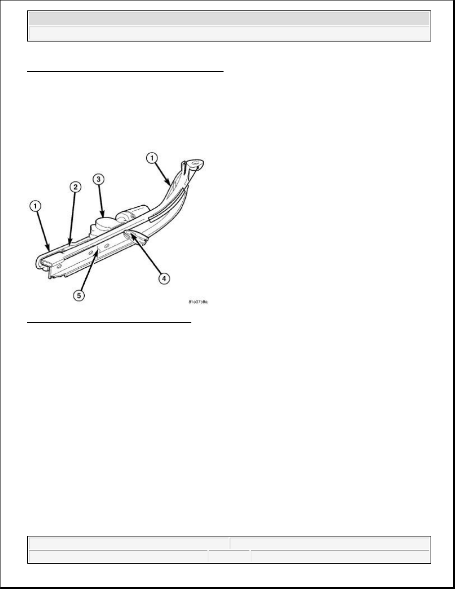
Body/Doors - Sliding/DOOR, Sliding - Adjustments for detailed instructions.
DRIVE ASSEMBLY
DESCRIPTION
DESCRIPTION
Fig. 1: Power Sliding Door Drive Assembly
Courtesy of CHRYSLER LLC
All vehicles equipped with power sliding doors will have two power sliding door drive assemblies. One drive
assembly for the left sliding door and one for the right. The drive assemblies are mounted in the vehicle body
cavity where the manual lower sliding door track would normally be located. The drive assemblies are attached
to the sliding door lower hinge via a drive bracket (also referred to as the drive tensioner). This bracket is
attached to a cable that moves fore and aft to open and close the power sliding doors.
The power sliding door drive assembly consists of the following parts:
The sliding door track (5)
The power sliding door drive cable, drive tensioner and pulleys (4)
The power sliding door motor (3)
The Power Sliding Door Control Module (PSDM) (2)
The power sliding door drive assembly wire harnesses (1)
The following are the serviceable components of the power sliding door drive assembly:
The PSDM
The PSDM to drive motor wire harness
2009 Dodge Grand Caravan SE
2009 ACCESSORIES & EQUIPMENT Power Sliding Door - Service Information - Grand Caravan, Town & Country
steve
Monday, May 23, 2011 1:59:19 PM
Page 31
© 2006 Mitchell Repair Information Company, LLC.

The lower door track, cable and motor
The power sliding door drive motor is not serviced as a separate component. If the motor is inoperative or
damaged the complete power sliding door drive assembly must be replaced. See Electrical - Power
Systems/Power Sliding Door/DRIVE ASSEMBLY - Removal. Whenever a new power sliding door drive
assembly service part is installed and the PSDM is functioning properly, the original PSDM must be transferred
to the new drive assembly. Refer to Electrical - Electronic Control Modules/Electronic Control
Modules/MODULE, Door - Removal , for the appropriate procedure.
REMOVAL
REMOVAL
WARNING:
To avoid serious or fatal injury on vehicles equipped with airbags, disable
the supplemental restraint system before attempting any steering wheel,
steering column, airbag, occupant classification system, seat belt
tensioner, impact sensor, or instrument panel component diagnosis or
service. Disconnect and isolate the battery negative (ground) cable, then
wait two minutes for the system capacitor to discharge before performing
further diagnosis or service. This is the only sure way to disable the
supplemental restraint system. Failure to take the proper precautions
could result in accidental airbag deployment.
WARNING:
To avoid serious or fatal injury, never strike or drop the side impact
sensor, as it can damage the impact sensor or affect its calibration. The
side impact sensor enables the system to deploy the side Supplemental
Restraint System (SRS) components. If an impact sensor is accidentally
dropped during service, the sensor must be scrapped and replaced with a
new unit. Failure to observe this warning could result in accidental,
incomplete, or improper side SRS component deployment.
2009 Dodge Grand Caravan SE
2009 ACCESSORIES & EQUIPMENT Power Sliding Door - Service Information - Grand Caravan, Town & Country
steve
Monday, May 23, 2011 1:59:19 PM
Page 32
© 2006 Mitchell Repair Information Company, LLC.
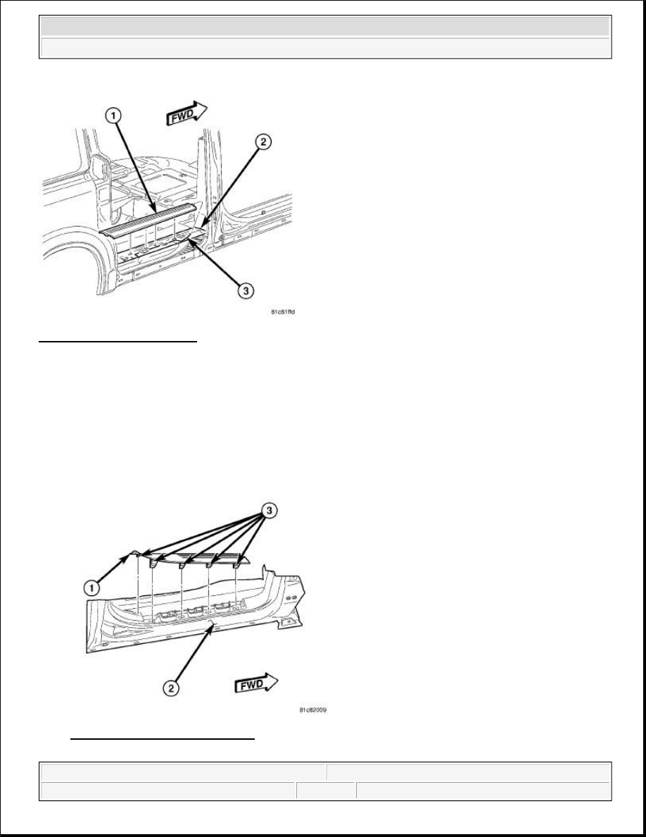
Fig. 2: Sliding Door Sill Plate
Courtesy of CHRYSLER LLC
1. Disconnect and isolate the battery negative cable.
2. Remove the sliding door sill plate.
a. Using a trim stick C-4755 or equivalent, pull up on the inside edge of the sill plate (1) to disengage
the clips from the body (3).
b. Carefully disengage the retaining tabs from the lower B-Pillar trim panel (2).
c. Remove the sill plate from the vehicle.
Fig. 3: Lower B-Pillar Trim Panel
Courtesy of CHRYSLER LLC
2009 Dodge Grand Caravan SE
2009 ACCESSORIES & EQUIPMENT Power Sliding Door - Service Information - Grand Caravan, Town & Country
steve
Monday, May 23, 2011 1:59:19 PM
Page 33
© 2006 Mitchell Repair Information Company, LLC.
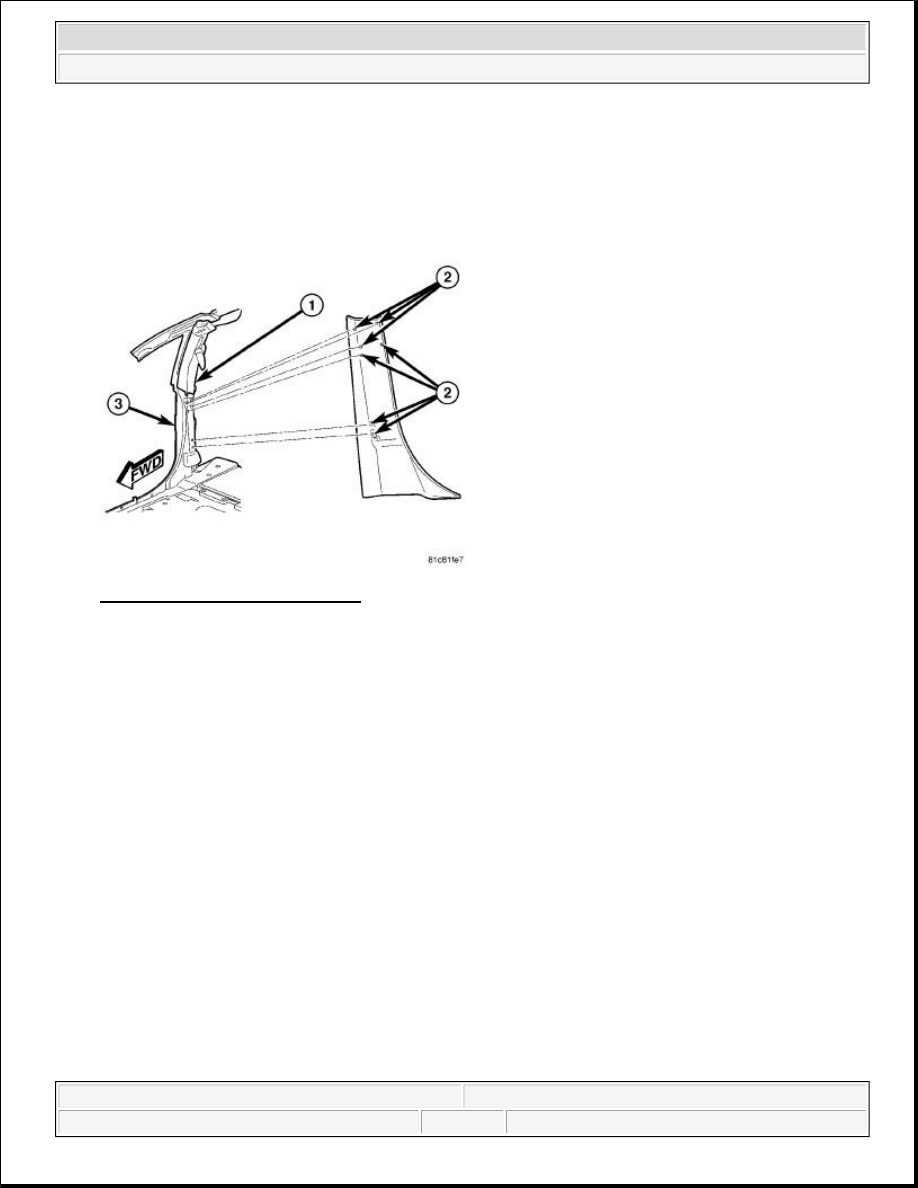
3. Remove the front door sill plate.
a. Using a trim stick C-4755 or equivalent, pull up on the inside edge of the sill plate (1) to disengage
the retaining clips (3) from the body (2).
b. Carefully disengage the retaining tab from the lower B-Pillar trim panel and remove the sill plate.
Fig. 4: Upper B-Pillar Trim Panel
Courtesy of CHRYSLER LLC
4. Remove the lower B-Pillar trim panel.
a. Using a trim stick C-4755 or equivalent, pull the B-Pillar trim panel away from the B-Pillar (3) to
disengage the retaining clips (2).
b. Disconnect the power sliding door B-Pillar switch electrical connector and remove the trim panel.
2009 Dodge Grand Caravan SE
2009 ACCESSORIES & EQUIPMENT Power Sliding Door - Service Information - Grand Caravan, Town & Country
steve
Monday, May 23, 2011 1:59:19 PM
Page 34
© 2006 Mitchell Repair Information Company, LLC.
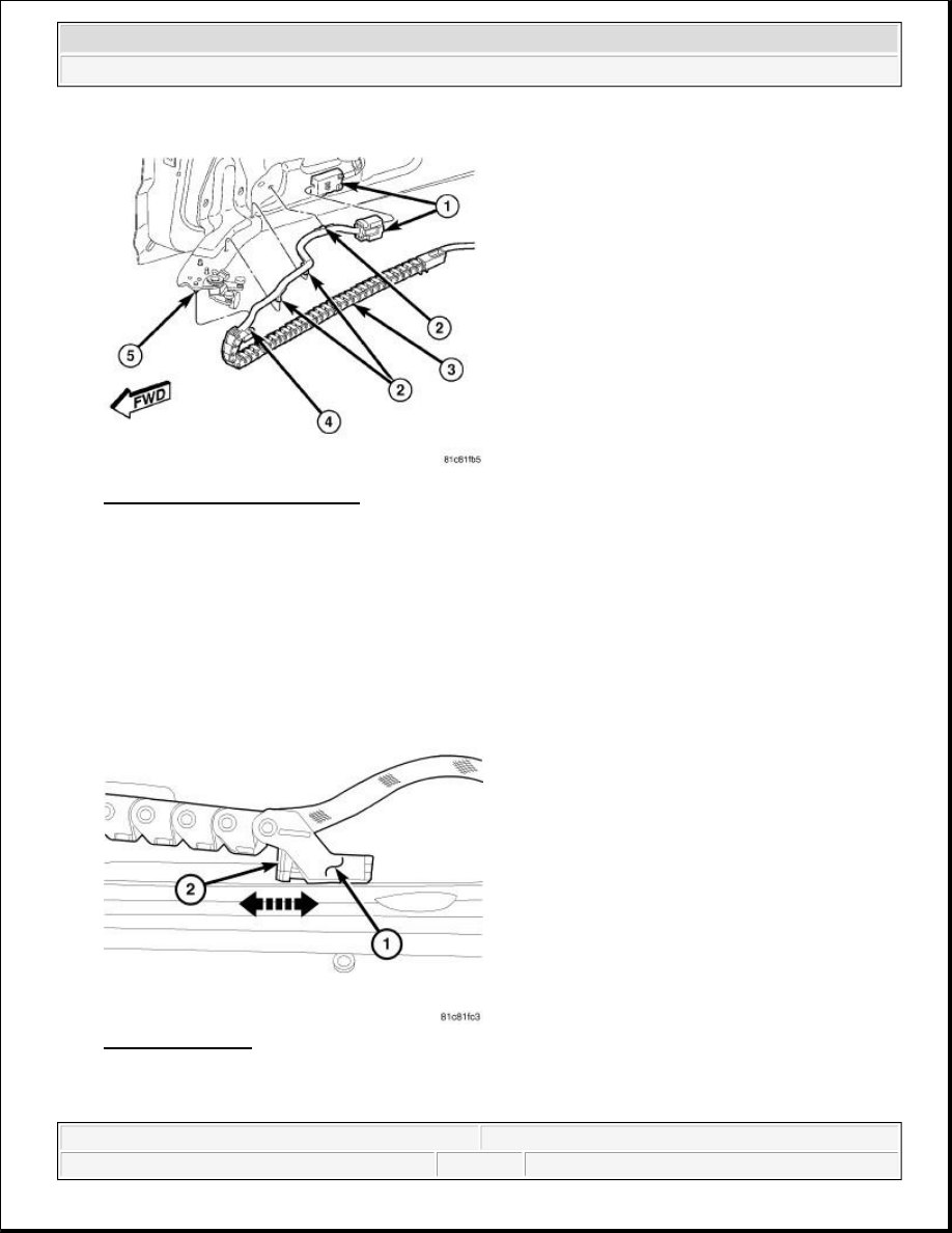
Fig. 5: Sliding Door Inner Panel
Courtesy of CHRYSLER LLC
5. Disconnect the sliding door wire harness connector from the bottom of the sliding door (1).
Fig. 6: Chain Link
Courtesy of CHRYSLER LLC
6. Using door trim panel tool C-4829A or equivalent, remove the wire harness routing clips (2) from the
NOTE:
Care should be taken when removing the z-clips used to attach the
harness to the sliding door lower hinge. Should the clips become
damaged or broken in any way, they should be replaced to ensure harness
is properly secured to the hinge.
2009 Dodge Grand Caravan SE
2009 ACCESSORIES & EQUIPMENT Power Sliding Door - Service Information - Grand Caravan, Town & Country
steve
Monday, May 23, 2011 1:59:19 PM
Page 35
© 2006 Mitchell Repair Information Company, LLC.
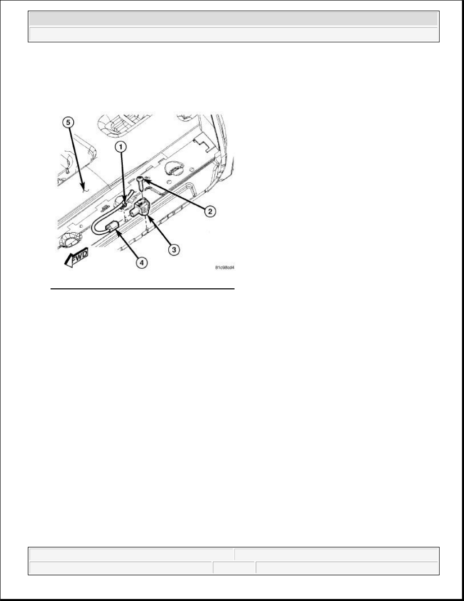
sliding door and the top of the sliding door lower hinge (5).
7. Pull locking tab (2) forward to release the rear wire harness chain link clip. Pull the chain link (1) down
off of the mounting pin on the sliding door lower hinge.
Fig. 7: Second Row Seating Side Impact Sensor
Courtesy of CHRYSLER LLC
8. Remove the screw (2) that secures the side impact sensor to the lower sliding door channel panel.
9. Disconnect the body wire harness connector (4) from the side impact sensor (3) on the top of the lower
sliding door channel panel.
10. Pull the side impact sensor straight up from the mounting location to unsnap the anti-rotation pin on the
base of the sensor from the clearance hole in the lower sliding door channel panel.
11. Remove the side impact sensor from the vehicle.
2009 Dodge Grand Caravan SE
2009 ACCESSORIES & EQUIPMENT Power Sliding Door - Service Information - Grand Caravan, Town & Country
steve
Monday, May 23, 2011 1:59:19 PM
Page 36
© 2006 Mitchell Repair Information Company, LLC.
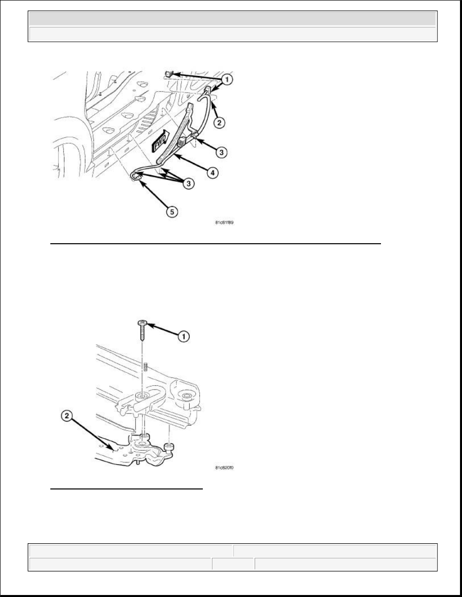
Fig. 8: Power Sliding Door Wire Harness & Second Row Seating Side Impact Sensors
Courtesy of CHRYSLER LLC
12. Using door trim panel tool C-4829A or equivalent, remove the wire harness routing clips located under
the drive assembly (3).
13. Pull the harness (4) out of the body channel and set aside.
Fig. 9: Driver Tensioner Retaining Bolt
Courtesy of CHRYSLER LLC
14. Remove the sliding door drive tensioner bolt (1) and remove the tensioner from the sliding door lower
hinge (2).
2009 Dodge Grand Caravan SE
2009 ACCESSORIES & EQUIPMENT Power Sliding Door - Service Information - Grand Caravan, Town & Country
steve
Monday, May 23, 2011 1:59:19 PM
Page 37
© 2006 Mitchell Repair Information Company, LLC.
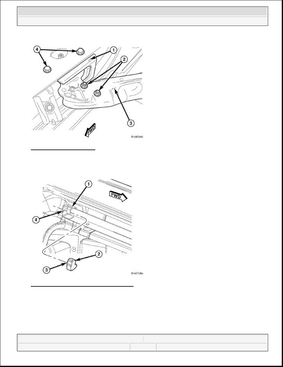
Fig. 10: Hold-Open Striker
Courtesy of CHRYSLER LLC
15. Remove the hold-open striker retaining bolts (4) and remove the hold open striker (1).
Fig. 11: Sliding Door Upper Track Bumper
Courtesy of CHRYSLER LLC
16. Apply masking tape to outside surface of quarter panel below the center roller channel, rearward of the
door opening.
17. Apply masking tape to door jamb area, rearward of the upper roller channel.
18. Remove the sliding door upper track bumper (2) by pulling out on the bottom edge of the bumper to
disengage the retaining feature (3) from the slot in the track (4).
2009 Dodge Grand Caravan SE
2009 ACCESSORIES & EQUIPMENT Power Sliding Door - Service Information - Grand Caravan, Town & Country
steve
Monday, May 23, 2011 1:59:19 PM
Page 38
© 2006 Mitchell Repair Information Company, LLC.
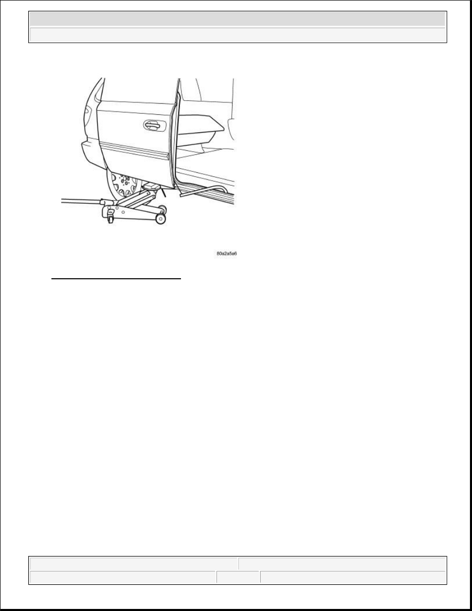
Fig. 12: Supporting Sliding Door
Courtesy of CHRYSLER LLC
19. Support sliding door on a suitable lifting device with a padded upper surface. The door must be moveable
forward and reward with lifting device in place.
20. Slide door rearward until the upper sliding door hinge roller disengages from the upper channel.
21. Continue moving the door rearward until the lower rollers exit the lower track.
NOTE:
Do not remove the door hinges from the door as it is not necessary for
servicing of the drive assembly. Removal of the hinges can effect door to
body fit resulting in abnormal door operation.
2009 Dodge Grand Caravan SE
2009 ACCESSORIES & EQUIPMENT Power Sliding Door - Service Information - Grand Caravan, Town & Country
steve
Monday, May 23, 2011 1:59:19 PM
Page 39
© 2006 Mitchell Repair Information Company, LLC.
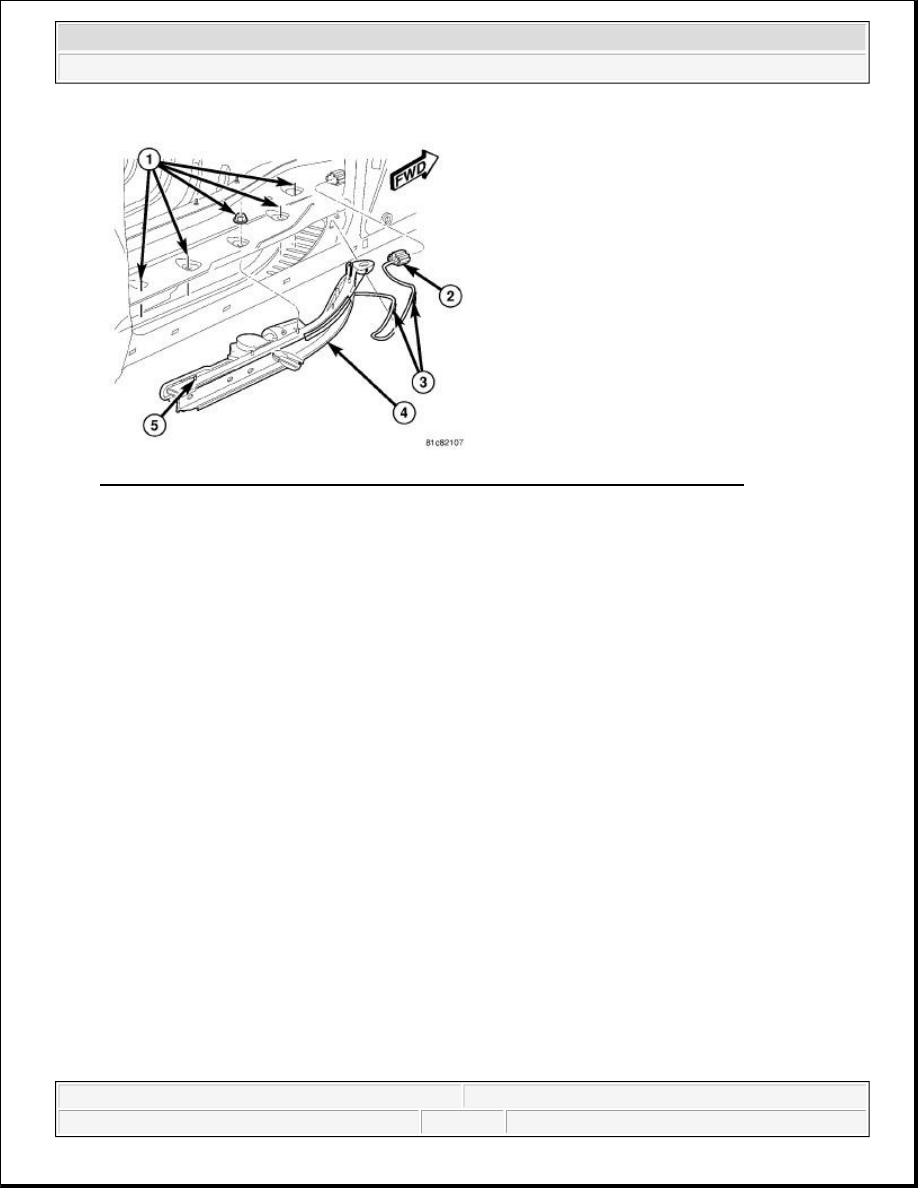
Fig. 13: Power Sliding Door Drive Assembly Retaining Nuts & Electrical Connector
Courtesy of CHRYSLER LLC
22. If necessary, remove the sliding door inner seal from the bottom of the door opening.
23. Remove the five power sliding door drive assembly retaining nuts (1).
24. Disconnect the power sliding door drive assembly electrical connector (3) at the front of the B-Pillar.
25. Carefully remove the wire harness routing clip from the body (2).
26. Carefully remove the power sliding door drive assembly (4) from the vehicle.
INSTALLATION
INSTALLATION
WARNING:
To avoid serious or fatal injury on vehicles equipped with airbags, disable
the Supplemental Restraint System (SRS) before attempting any steering
wheel, steering column, airbag, seat belt tensioner, impact sensor, or
instrument panel component diagnosis or service. Disconnect and isolate
the battery negative (ground) cable, then wait two minutes for the system
capacitor to discharge before performing further diagnosis or service.
This is the only sure way to disable the SRS. Failure to take the proper
precautions could result in accidental airbag deployment.
WARNING:
To avoid serious or fatal injury, never strike or drop the side impact
sensor, as it can damage the impact sensor or affect its calibration. The
side impact sensor enables the system to deploy the side Supplemental
Restraint System (SRS) components. If an impact sensor is accidentally
dropped during service, the sensor must be scrapped and replaced with a
new unit. Failure to observe this warning could result in accidental,
incomplete, or improper side SRS component deployment.
2009 Dodge Grand Caravan SE
2009 ACCESSORIES & EQUIPMENT Power Sliding Door - Service Information - Grand Caravan, Town & Country
steve
Monday, May 23, 2011 1:59:19 PM
Page 40
© 2006 Mitchell Repair Information Company, LLC.
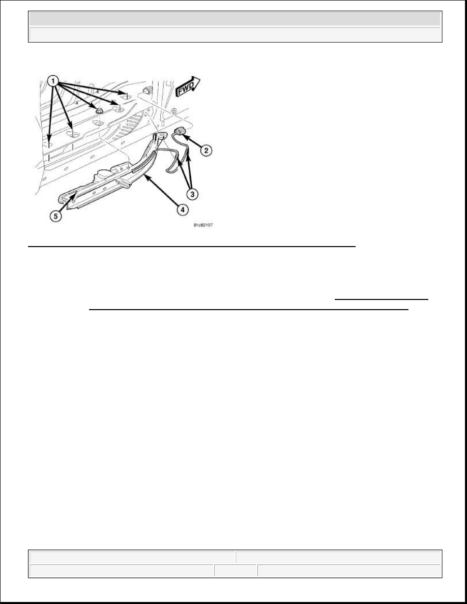
Fig. 14: Power Sliding Door Drive Assembly Retaining Nuts & Electrical Connector
Courtesy of CHRYSLER LLC
1. Position the power sliding door drive assembly into the vehicle.
a. Insert the drive assembly (4) into the sliding door sill cavity, curved end first by the B-Pillar area.
b. Rotate the straight end of the drive assembly toward the vehicle so that the entire assembly is in the
sill cavity.
c. Lift the drive assembly up to insert the studs (5) into the floor pan holes.
d. Install the five power sliding door drive assembly retaining nuts (1) finger tight.
2. Tighten the power sliding door drive assembly retaining nuts (1).
a. Tighten the forward most nut to 9 N.m (80 in. lbs).
b. Tighten the rearward most nut to 9 N.m (80 in. lbs).
c. Tighten the remaining three nuts, front to back to 9 N.m (80 in. lbs).
3. Attach the wiring harness retaining clips to the body (3).
4. Connect the power sliding door drive assembly electrical connector (2) at the front of the B-Pillar.
NOTE:
The service power sliding door drive assembly does not include the Power
Sliding Door Control Module (PSDM). The PSDM must be transferred from the
original drive assembly to the new service part. Refer to Electrical - Electronic
Control Modules/Electronic Control Modules/MODULE, Door - Installation for
the PSDM installation procedure.
2009 Dodge Grand Caravan SE
2009 ACCESSORIES & EQUIPMENT Power Sliding Door - Service Information - Grand Caravan, Town & Country
steve
Monday, May 23, 2011 1:59:19 PM
Page 41
© 2006 Mitchell Repair Information Company, LLC.
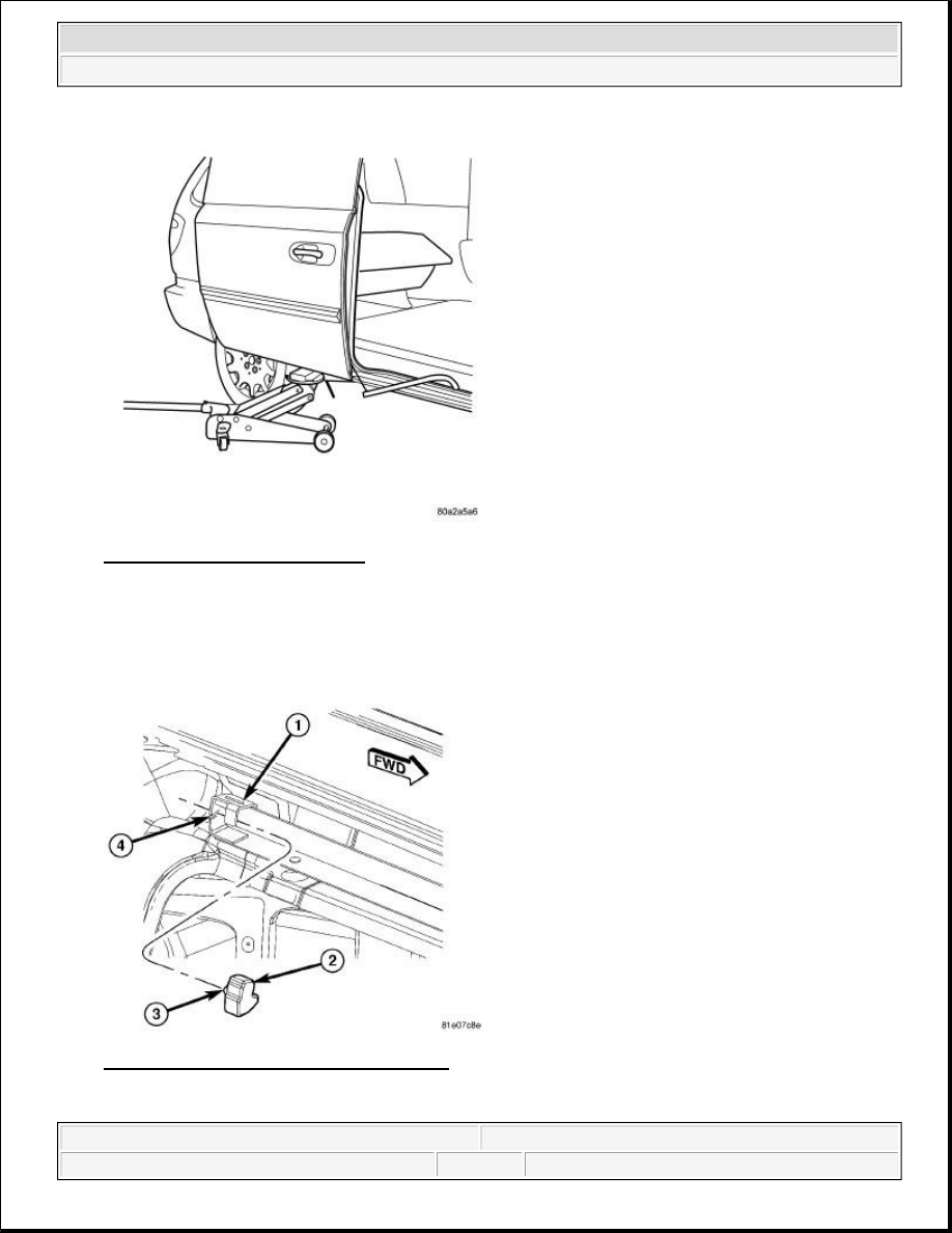
Fig. 15: Supporting Sliding Door
Courtesy of CHRYSLER LLC
5. With the door still supported with an appropriate lifting device, roll door forward until lower roller
engages into rear of the lower track.
6. Continue rolling the door forward to engage the upper sliding door hinge into the upper channel.
Fig. 16: Sliding Door Upper Track Bumper
Courtesy of CHRYSLER LLC
2009 Dodge Grand Caravan SE
2009 ACCESSORIES & EQUIPMENT Power Sliding Door - Service Information - Grand Caravan, Town & Country
steve
Monday, May 23, 2011 1:59:19 PM
Page 42
© 2006 Mitchell Repair Information Company, LLC.
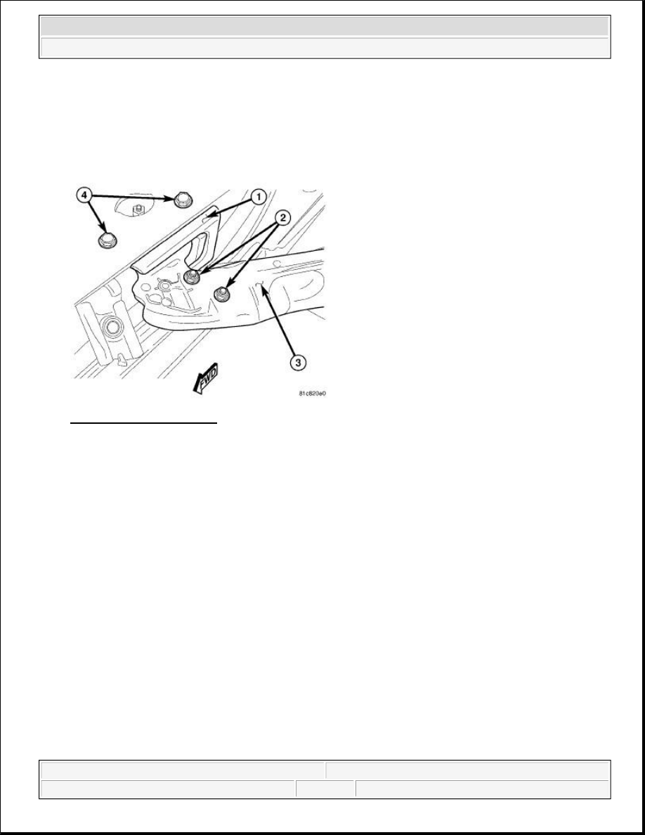
7. Install the power sliding door upper track bumper.
a. Roll top edge of bumper (2) under track flange (1) ensuring the back surface of bumper is
contacting the surface on track.
b. Push on left corner of bumper to positively seat retaining feature (3) into the track slot (4).
Fig. 17: Hold-Open Striker
Courtesy of CHRYSLER LLC
8. If removed during power sliding door drive assembly removal, install the sliding door inner seal onto the
bottom of the door opening.
9. Position the hold-open striker (1) into the lower sill cavity.
10. Install the hold open striker retaining bolts. Tighten bolts, forward most bolt first, to 10 N.m (90 in. lbs).
11. Remove the lifting device supporting the door.
2009 Dodge Grand Caravan SE
2009 ACCESSORIES & EQUIPMENT Power Sliding Door - Service Information - Grand Caravan, Town & Country
steve
Monday, May 23, 2011 1:59:19 PM
Page 43
© 2006 Mitchell Repair Information Company, LLC.
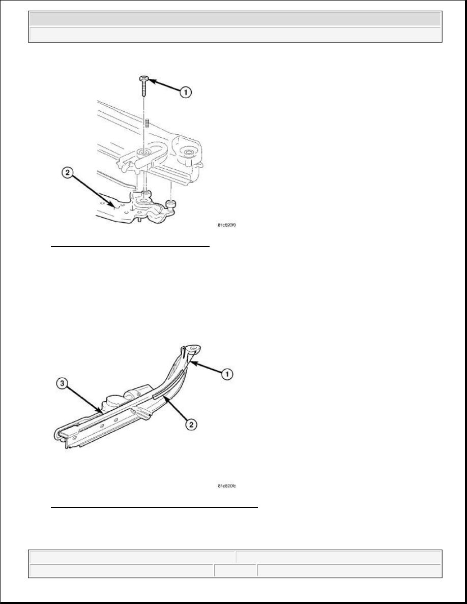
Fig. 18: Driver Tensioner Retaining Bolt
Courtesy of CHRYSLER LLC
12. Install the sliding door drive tensioner onto the sliding door lower hinge.
a. Position the drive tensioner onto the top of the lower hinge (2) so that the alignment pin engages
with the hole.
b. Install the drive tensioner retaining bolt (1). Tighten bolt to 14.5 N.m (130 in. lbs).
Fig. 19: Drive Cable, Cable Guide & Drive Assembly
Courtesy of CHRYSLER LLC
CAUTION: Damage to the power sliding door and drive assembly can result
2009 Dodge Grand Caravan SE
2009 ACCESSORIES & EQUIPMENT Power Sliding Door - Service Information - Grand Caravan, Town & Country
steve
Monday, May 23, 2011 1:59:19 PM
Page 44
© 2006 Mitchell Repair Information Company, LLC.
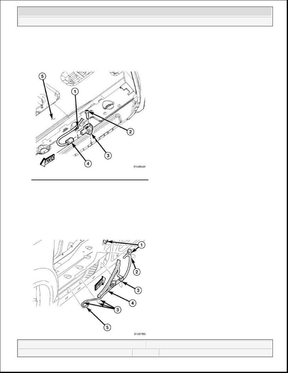
Fig. 20: Second Row Seating Side Impact Sensor
Courtesy of CHRYSLER LLC
13. Position the side impact sensor (3) to the top of the lower sliding door channel panel.
14. Align the anti-rotation pin on the base of the sensor with the clearance hole in the lower sliding door
channel panel, then press down on the sensor firmly and evenly to snap the pin into place.
15. Install and tighten the screw (2) that secures the side impact sensor to the lower sliding door channel
panel. Tighten the screw to 9 N.m (80 in. lbs.).
from improper alignment of the drive cable. Insure the drive cable (1)
is positioned on the cable guide (2) at the front of the drive assembly
(3).
2009 Dodge Grand Caravan SE
2009 ACCESSORIES & EQUIPMENT Power Sliding Door - Service Information - Grand Caravan, Town & Country
steve
Monday, May 23, 2011 1:59:19 PM
Page 45
© 2006 Mitchell Repair Information Company, LLC.
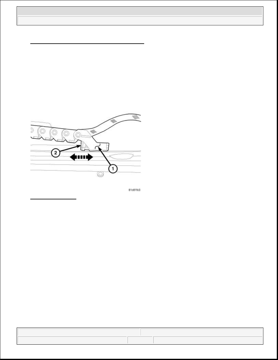
Fig. 21: Side Impact Sensor Electrical Connector
Courtesy of CHRYSLER LLC
16. Install the power sliding door wire harness.
a. Position the wire harness (4) into the track cavity and install the pushpin clips (3) located under the
drive assembly.
b. Connect the side impact sensor electrical connector (5).
c. If the door harness B-Pillar connector was disconnected, reconnect it at this time (1).
Fig. 22: Chain Link
Courtesy of CHRYSLER LLC
17. Position the power sliding door wire harness chain link (1) onto the mounting pin on the lower side of the
sliding door lower hinge. Push locking tab rearward to secure the rear harness chain link clip (2).
2009 Dodge Grand Caravan SE
2009 ACCESSORIES & EQUIPMENT Power Sliding Door - Service Information - Grand Caravan, Town & Country
steve
Monday, May 23, 2011 1:59:19 PM
Page 46
© 2006 Mitchell Repair Information Company, LLC.

Fig. 23: Sliding Door Inner Panel
Courtesy of CHRYSLER LLC
18. Connect the sliding door wire harness connector at the bottom of the sliding door (1).
19. Install pushpin clips on top of sliding door lower hinge and sliding door inner panel (2).
Fig. 24: Upper B-Pillar Trim Panel
Courtesy of CHRYSLER LLC
20. Install the lower B-Pillar trim panel.
a. Insert the mounting tab at the top of the lower B-Pillar trim panel into the upper B-Pillar trim panel
(1).
b. Align the retaining clips (2) with the mounting slots in the B-Pillar (3).
2009 Dodge Grand Caravan SE
2009 ACCESSORIES & EQUIPMENT Power Sliding Door - Service Information - Grand Caravan, Town & Country
steve
Monday, May 23, 2011 1:59:19 PM
Page 47
© 2006 Mitchell Repair Information Company, LLC.
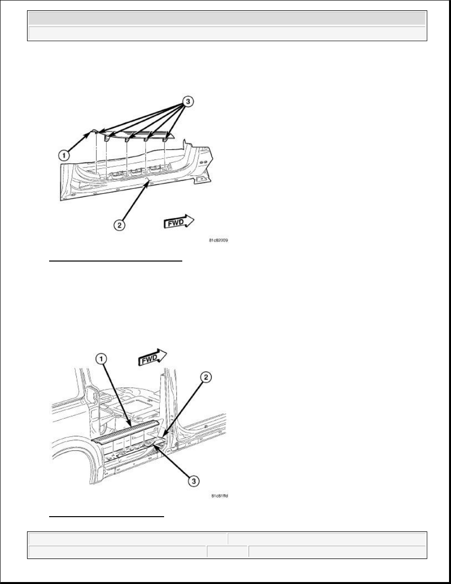
c. Push the trim panel toward the B-Pillar to fully seat all retaining clips.
Fig. 25: Lower B-Pillar Trim Panel
Courtesy of CHRYSLER LLC
21. Install the front door sill plate.
a. Insert the mounting tab at the rear of the front door sill plate into the lower B-Pillar trim panel (1).
b. Align the retaining clips (3) with the mounting slots in the door opening (2).
c. Push down on the sill plate to fully seat all retaining clips.
Fig. 26: Sliding Door Sill Plate
Courtesy of CHRYSLER LLC
2009 Dodge Grand Caravan SE
2009 ACCESSORIES & EQUIPMENT Power Sliding Door - Service Information - Grand Caravan, Town & Country
steve
Monday, May 23, 2011 1:59:19 PM
Page 48
© 2006 Mitchell Repair Information Company, LLC.
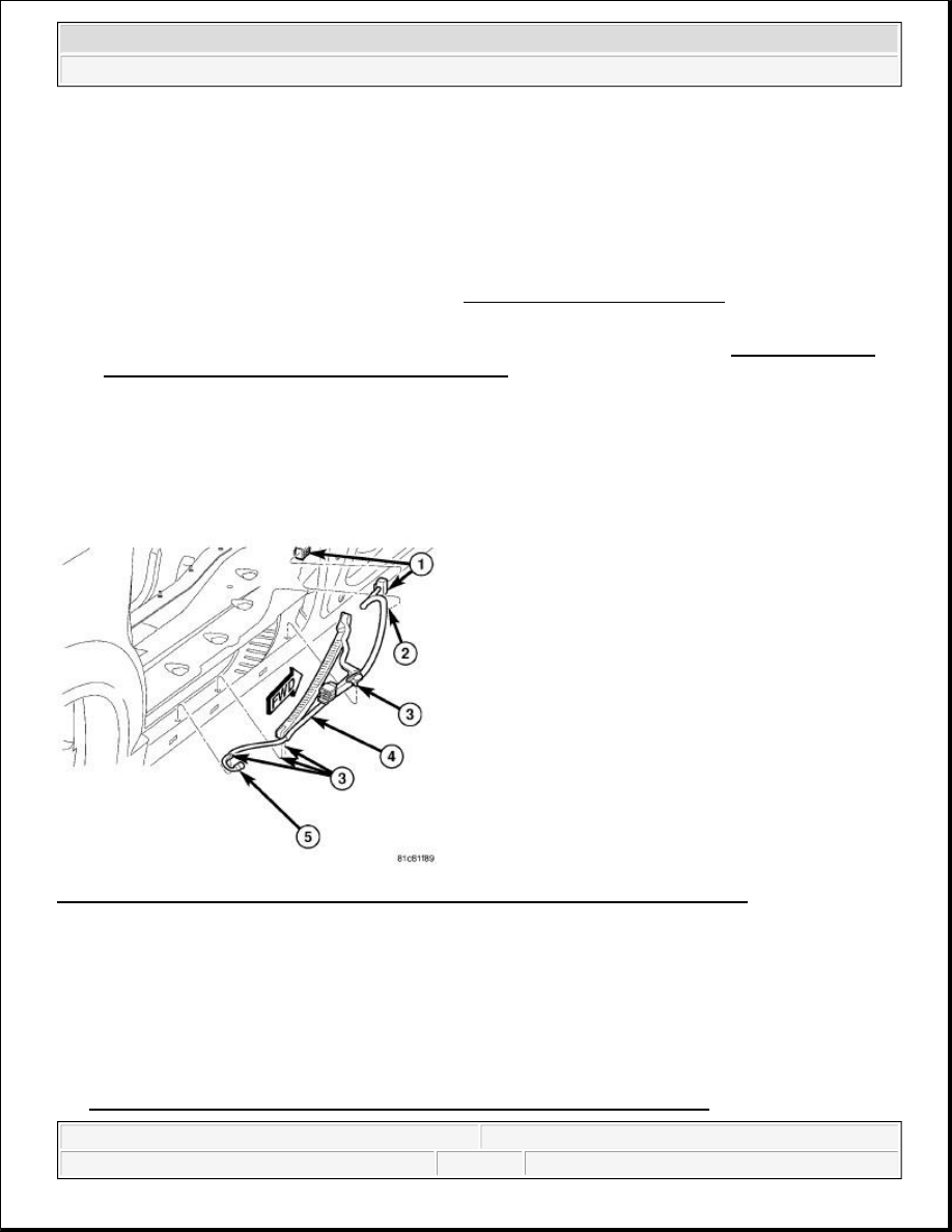
22. Install the sliding door sill plate.
a. Insert the mounting tab at the front of the sliding door sill plate into the lower B-Pillar trim panel
(2).
b. Align the retaining clips on the sill plate (1) with the mounting slots in the door opening (3).
c. Push down on the sill plate to fully seat all retaining clips.
23. Perform the Supplemental Restraint System (SRS) verification test procedure due to removal of the
second row seating side impact sensor. Refer to Restraints - Standard Procedure .
24. Connect the battery negative cable.
25. Perform the power sliding door learn cycle and verify proper system operation. See Electrical - Power
Systems/Power Sliding Door - Standard Procedure.
HARNESS, WIRING
DESCRIPTION
DESCRIPTION
Fig. 27: Power Sliding Door Wire Harness & Second Row Seating Side Impact Sensors
Courtesy of CHRYSLER LLC
The power sliding door wire harness (4) supplies power (12 v), ground and various hardwired and data bus
electrical signals to the power sliding door components and the rear door control module for various power door
functions. The harness connects at the B-pillar at one end (1) and the sliding door at the other. It is secured to
the body with push pin style retainers (2 and 3). A plastic chain or wiring track covers the wire harness
assembly and is used to protect the wire harness from abrasion and/or tangling. This wiring track is replaced
with the wire harness assembly. The wire harness assembly also supplies the connection for the second row
seating side impact sensors (5). Should the harness be damaged it should be replaced as a complete assembly.
See Electrical - Power Systems/Power Sliding Door/HARNESS, Wiring - Removal.
2009 Dodge Grand Caravan SE
2009 ACCESSORIES & EQUIPMENT Power Sliding Door - Service Information - Grand Caravan, Town & Country
steve
Monday, May 23, 2011 1:59:19 PM
Page 49
© 2006 Mitchell Repair Information Company, LLC.

OPERATION
OPERATION
The wire harness and plastic wiring track provide a safe and reliable means of supplying power, ground and
various hardwired and data bus electrical signals to the power sliding door components and the rear door control
module for various power door functions. During sliding door movement the wiring track is designed to fold
and unfold like the links in a chain.
REMOVAL
REMOVAL
WARNING:
To avoid serious or fatal injury on vehicles equipped with airbags, disable
the supplemental restraint system before attempting any steering wheel,
steering column, airbag, occupant classification system, seat belt
tensioner, impact sensor, or instrument panel component diagnosis or
service. Disconnect and isolate the battery negative (ground) cable, then
wait two minutes for the system capacitor to discharge before performing
further diagnosis or service. This is the only sure way to disable the
supplemental restraint system. Failure to take the proper precautions
could result in accidental airbag deployment.
WARNING:
To avoid serious or fatal injury, never strike or drop the side impact
sensor, as it can damage the impact sensor or affect its calibration. The
side impact sensor enables the system to deploy the side Supplemental
Restraint System (SRS) components. If an impact sensor is accidentally
dropped during service, the sensor must be scrapped and replaced with a
new unit. Failure to observe this warning could result in accidental,
incomplete, or improper side SRS component deployment.
2009 Dodge Grand Caravan SE
2009 ACCESSORIES & EQUIPMENT Power Sliding Door - Service Information - Grand Caravan, Town & Country
steve
Monday, May 23, 2011 1:59:19 PM
Page 50
© 2006 Mitchell Repair Information Company, LLC.
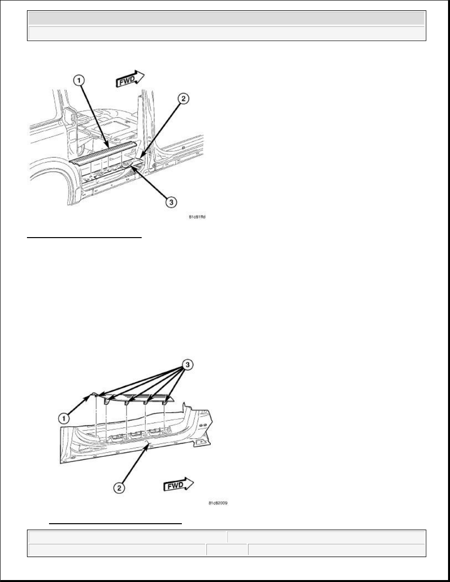
Fig. 28: Sliding Door Sill Plate
Courtesy of CHRYSLER LLC
1. Disconnect and isolate the battery negative cable.
2. Remove the sliding door sill plate.
a. Using a trim stick C-4755 or equivalent, pull up on the inside edge of the sill plate (1) to disengage
the clips from the body (3).
b. Carefully disengage the retaining tabs from the lower B-Pillar trim panel and rear quarter trim panel
(2).
c. Remove the sill plate from the vehicle.
Fig. 29: Lower B-Pillar Trim Panel
2009 Dodge Grand Caravan SE
2009 ACCESSORIES & EQUIPMENT Power Sliding Door - Service Information - Grand Caravan, Town & Country
steve
Monday, May 23, 2011 1:59:19 PM
Page 51
© 2006 Mitchell Repair Information Company, LLC.
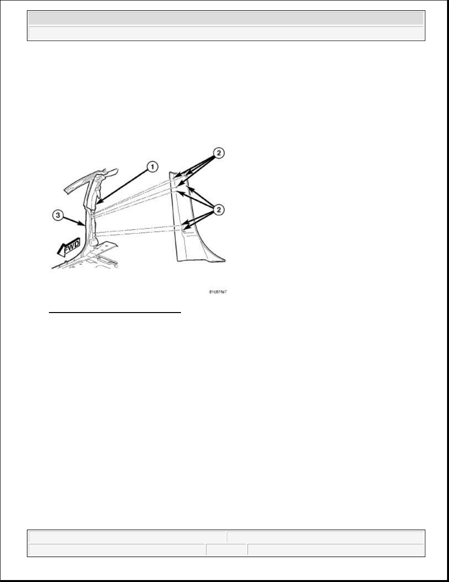
Courtesy of CHRYSLER LLC
3. Remove the front door sill plate.
a. Using a trim stick C-4755 or equivalent, pull up on the inside edge of the sill plate (1) to disengage
the retaining clips (3) from the body (2).
b. Carefully disengage the retaining tab from the lower B-Pillar trim panel and remove the sill plate.
Fig. 30: Upper B-Pillar Trim Panel
Courtesy of CHRYSLER LLC
4. Remove the lower B-Pillar trim panel.
a. Using a trim stick C-4755 or equivalent, pull the B-Pillar trim panel away from the B-Pillar (3) to
disengage the retaining clips (2).
b. Disconnect the power sliding door B-Pillar switch electrical connector and remove the trim panel.
2009 Dodge Grand Caravan SE
2009 ACCESSORIES & EQUIPMENT Power Sliding Door - Service Information - Grand Caravan, Town & Country
steve
Monday, May 23, 2011 1:59:19 PM
Page 52
© 2006 Mitchell Repair Information Company, LLC.
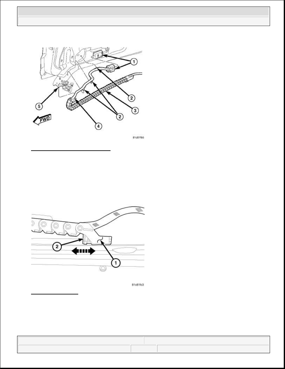
Fig. 31: Sliding Door Inner Panel
Courtesy of CHRYSLER LLC
5. Disconnect the sliding door wire harness connector from the bottom of the sliding door (1).
6. Using door trim panel tool C-4829A or equivalent, remove the wire harness routing clips (2) from the
sliding door and the top of the sliding door lower hinge.
Fig. 32: Chain Link
Courtesy of CHRYSLER LLC
7. Pull locking tab (2) forward to release the rear wire harness chain link clip. Pull the chain link (1) down
off of the mounting pin on the sliding door lower hinge.
2009 Dodge Grand Caravan SE
2009 ACCESSORIES & EQUIPMENT Power Sliding Door - Service Information - Grand Caravan, Town & Country
steve
Monday, May 23, 2011 1:59:19 PM
Page 53
© 2006 Mitchell Repair Information Company, LLC.
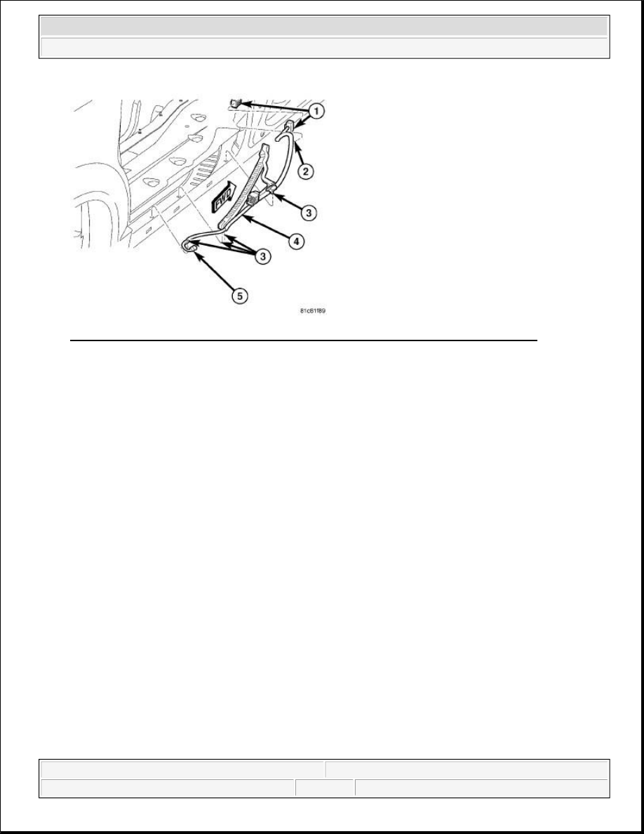
Fig. 33: Power Sliding Door Wire Harness & Second Row Seating Side Impact Sensors
Courtesy of CHRYSLER LLC
8. Disconnect the second row seating side impact sensor electrical connector (5).
9. Using door trim panel tool C-4829A or equivalent, remove the wire harness routing clips located under
the drive assembly (3) and near the B-pillar (2).
10. Disconnect the wire harness connector at the B-pillar (1).
11. Pull the harness (4) out of the body channel and remove from vehicle.
INSTALLATION
INSTALLATION
WARNING:
To avoid serious or fatal injury on vehicles equipped with airbags, disable
the Supplemental Restraint System (SRS) before attempting any steering
wheel, steering column, airbag, seat belt tensioner, impact sensor, or
instrument panel component diagnosis or service. Disconnect and isolate
the battery negative (ground) cable, then wait two minutes for the system
capacitor to discharge before performing further diagnosis or service.
This is the only sure way to disable the SRS. Failure to take the proper
precautions could result in accidental airbag deployment.
WARNING:
To avoid serious or fatal injury, never strike or drop the side impact
sensor, as it can damage the impact sensor or affect its calibration. The
side impact sensor enables the system to deploy the side Supplemental
Restraint System (SRS) components. If an impact sensor is accidentally
dropped during service, the sensor must be scrapped and replaced with a
new unit. Failure to observe this warning could result in accidental,
incomplete, or improper side SRS component deployment.
2009 Dodge Grand Caravan SE
2009 ACCESSORIES & EQUIPMENT Power Sliding Door - Service Information - Grand Caravan, Town & Country
steve
Monday, May 23, 2011 1:59:19 PM
Page 54
© 2006 Mitchell Repair Information Company, LLC.
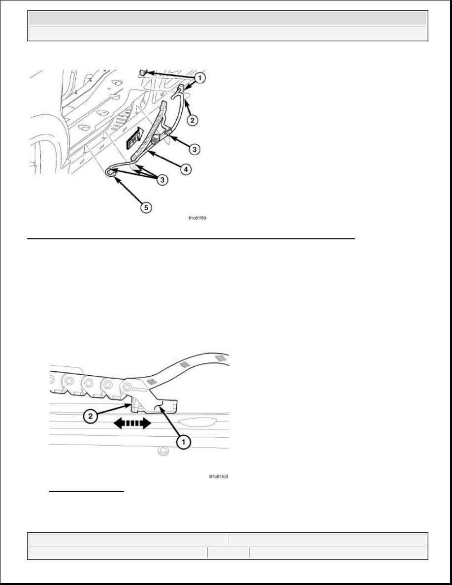
Fig. 34: Power Sliding Door Wire Harness & Second Row Seating Side Impact Sensors
Courtesy of CHRYSLER LLC
1. Position the wire harness (4) into the sliding door track cavity and install the pushpin clips (3) located
under the drive assembly.
2. Install the pushpin clip at the B-pillar (2).
3. Connect the sliding door wire harness B-pillar connector (1).
4. Connect the side impact sensor electrical connector (5).
Fig. 35: Chain Link
Courtesy of CHRYSLER LLC
5. Position the power sliding door wire harness chain link (1) onto the mounting pin on the lower side of the
sliding door lower hinge. Push locking tab rearward to secure the rear harness chain link clip (2).
2009 Dodge Grand Caravan SE
2009 ACCESSORIES & EQUIPMENT Power Sliding Door - Service Information - Grand Caravan, Town & Country
steve
Monday, May 23, 2011 1:59:19 PM
Page 55
© 2006 Mitchell Repair Information Company, LLC.
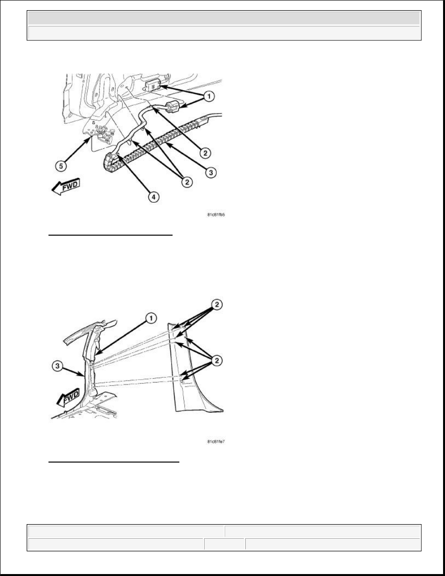
Fig. 36: Sliding Door Inner Panel
Courtesy of CHRYSLER LLC
6. Connect the sliding door wire harness connector at the bottom of the sliding door (1).
7. Install pushpin clips on top of sliding door lower hinge and sliding door inner panel (2).
Fig. 37: Upper B-Pillar Trim Panel
Courtesy of CHRYSLER LLC
8. Install the lower B-Pillar trim panel.
a. Insert the mounting tab at the top of the lower B-Pillar trim panel into the upper B-Pillar trim panel
(1).
b. Align the retaining clips (2) with the mounting slots in the B-Pillar (3).
2009 Dodge Grand Caravan SE
2009 ACCESSORIES & EQUIPMENT Power Sliding Door - Service Information - Grand Caravan, Town & Country
steve
Monday, May 23, 2011 1:59:19 PM
Page 56
© 2006 Mitchell Repair Information Company, LLC.

c. Push the trim panel toward the B-Pillar to fully seat all retaining clips.
Fig. 38: Lower B-Pillar Trim Panel
Courtesy of CHRYSLER LLC
9. Install the front door sill plate.
a. Insert the mounting tab at the rear of the front door sill plate into the lower B-Pillar trim panel (1).
b. Align the retaining clips (3) with the mounting slots in the door opening (2).
c. Push down on the sill plate to fully seat all retaining clips.
Fig. 39: Sliding Door Sill Plate
Courtesy of CHRYSLER LLC
2009 Dodge Grand Caravan SE
2009 ACCESSORIES & EQUIPMENT Power Sliding Door - Service Information - Grand Caravan, Town & Country
steve
Monday, May 23, 2011 1:59:19 PM
Page 57
© 2006 Mitchell Repair Information Company, LLC.

10. Install the sliding door sill plate.
a. Insert the mounting tab at the front of the sliding door sill plate into the lower B-Pillar trim panel
(2).
b. Align the retaining clips on the sill plate (1) with the mounting slots in the door opening (3).
c. Push down on the sill plate to fully seat all retaining clips.
Connect the battery negative cable.
SWITCH, B-PILLAR
DESCRIPTION
DESCRIPTION
The B-pillar switches are located on the interior of the vehicle, on the B-pillar trim panels. These switches serve
as an open and close command switch for the appropriate power sliding door.
For switch on the overhead console removal. Refer to Electrical - Message Systems/Overhead Console -
Removal . Refer to Electrical - Message Systems/Overhead Console - Installation .
OPERATION
OPERATION
The B-pillar switch is located on the lower B-pillar trim panel and allows the rear occupants to power open or
close the sliding doors. The B-pillar switch is an R-Mux switch that has a resistance of 3.6K ohms and 16K
ohms depending on switch position. When pressed the B-pillar switch will have a nominal resistance of 3.9K.
The B-pillar switches are hardwired to the Totally Integrated Power Module (TIPM). The Power Sliding Door
Control Module (PSDM) receives the message for operation status via the Controller Area Network (CAN) data
bus. If all the necessary conditions are met the PSDM will then perform the requested operation. The B-pillar
switch lockout feature must be disabled and the sliding door must be unlocked in order for the B-pillar switch to
function.
The hard wired circuits for the B-pillar sliding door switches may be diagnosed using conventional diagnostic
tools and procedures. Refer to POWER SLIDING DOOR MODULE, LEFT (PSDML) - ELECTRICAL
DIAGNOSTICS and/or POWER SLIDING DOOR MODULE, RIGHT (PSDMR) - ELECTRICAL
DIAGNOSTICS . However, conventional diagnostic methods will not prove conclusive in the diagnosis of the
electronic controls and communication between other modules and devices that provide some features of the
power sliding door system. The most reliable, efficient, and accurate means to diagnose the B-pillar switches or
the electronic controls and communication related to the power sliding door system operation requires the use of
a diagnostic scan tool. Refer to the appropriate diagnostic information.
REMOVAL
REMOVAL
2009 Dodge Grand Caravan SE
2009 ACCESSORIES & EQUIPMENT Power Sliding Door - Service Information - Grand Caravan, Town & Country
steve
Monday, May 23, 2011 1:59:19 PM
Page 58
© 2006 Mitchell Repair Information Company, LLC.
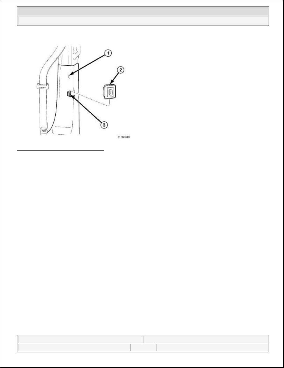
Fig. 40: Sliding Door B Pillar Switch
Courtesy of CHRYSLER LLC
1. Disconnect and isolate the battery negative cable.
2. Using a trim stick (special tool # C-4755) or equivalent, gently pry the leading upper edge of the B-pillar
switch (2) away from the B-pillar trim (1).
3. Once the upper edge is free from the B-pillar trim, rock the switch out of the switch opening.
4. Disconnect the B-pillar switch electrical connector (3).
5. Remove the B-pillar switch from the vehicle.
INSTALLATION
INSTALLATION
2009 Dodge Grand Caravan SE
2009 ACCESSORIES & EQUIPMENT Power Sliding Door - Service Information - Grand Caravan, Town & Country
steve
Monday, May 23, 2011 1:59:19 PM
Page 59
© 2006 Mitchell Repair Information Company, LLC.

Fig. 41: Sliding Door B Pillar Switch
Courtesy of CHRYSLER LLC
1. Position the B-pillar switch (2) into the vehicle.
2. Connect the B-pillar switch electrical connector (3).
3. Hook the lower edge of the B-pillar switch (2) onto the B-pillar trim panel (1) and push the switch firmly
into position.
4. Connect the battery negative cable.
2009 Dodge Grand Caravan SE
2009 ACCESSORIES & EQUIPMENT Power Sliding Door - Service Information - Grand Caravan, Town & Country
steve
Monday, May 23, 2011 1:59:19 PM
Page 60
© 2006 Mitchell Repair Information Company, LLC.
Wyszukiwarka
Podobne podstrony:
POWER DOOR LOCKS
Power Door Lock Circuit
door locks power
BMW E38 schematic Power door locks
93ZJ Secc 8P Power Door Locks
prezentacja power media
Power D, zebranie zarządu
karty płatnicze (power point)
elastyczność popytu (power point)
kryptologia w bankowości (power point)
europejski system nagród (power point)
TQM zarządzanie jakością (power point)
V80 Power Management 11May04
Popular Mechanics Repairing Power Antennas
74 Sliding Roof Convertible
[ebook renewable energy] Home Power Magazine 'Correct Solar Panel Tilt Angle to Sun'
Iron Maiden Power Slave
McMartin LT2000D Power Amplifier
1 Fragment wywiadu z zespołem Full Power Spirit
więcej podobnych podstron