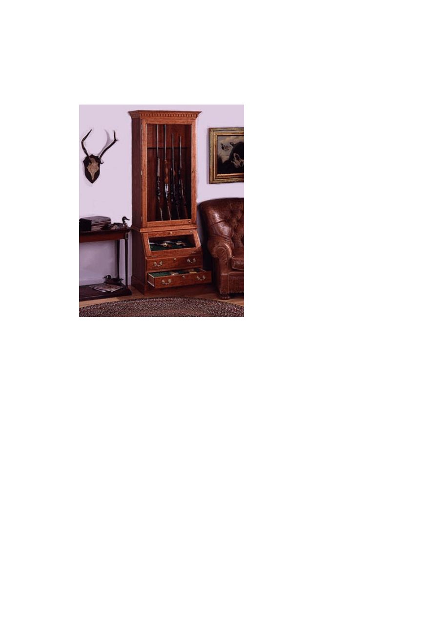
Top Gun
A well-crafted cherry cabinet for long arms and pistols.
Many firearms are laid flat and slid under a bed, or they are
stood in a closet or buried in a drawer. Others are simply
laid across bland-looking racks. It doesn't have to be that
way. Firearms should be stored in a convenient and secure
place that allows us to admire and handle them or easily
remove them for hunting or target practice. We think this
gun cabinet succeeds on all counts. Long arms are stood in
the upper case, pistols displayed in the lower case.
Supplies and ammunition may be stored in the two drawers
below. With security in mind, the upper and lower doors are
equipped with locks, as are the drawers. The glazing is
impact-resistant acrylic sheet.
A gun cabinet can be an eye-catching piece of furniture,
and we've designed this piece to be as elegant as anything
else you would want to build. It's constructed of cherry
plywood and solid cherry. The upper and lower cases are
lighted with 20-watt, low-voltage halogen lamps. And the
moldings, hardware and proportions all suggest refinement,
not merely storage.
As projects go, this requires rather advanced skills. If
you've already built a cabinet of one type or another, then it
should be well within your capability. If you haven't built a
cabinet yet, then study the plans and materials list carefully
before beginning.
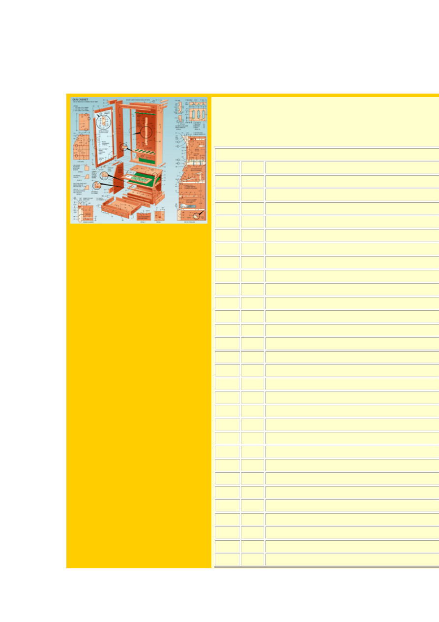
MATERIALS LIST--GUN CABINET
Key No. Size and description
A1
2
3/4 x 11 7/16 x 55" cherry plywood (side)
A2
2
3/16 x 3/4 x 55" cherry (edge band)
B
2
3/4 x 10 7/8 x 27 1/2" cherry ply. (top/bottom
C
1
1/4 x 27 3/4 x 53 1/2" cherry plywood (back)
D1
1
3/4 x 3 7/8 x 27" cherry (rail)
D2
1
3/4 x 1 5/8 x 27" cherry (rail)
D3
2
3/4 x 1 x 52 3/4" cherry (stiffener)
E1
1
1/2 x 9 7/16 x 27" plywood (butt rest)
E2
1
1/4 x 9 7/16 x 27" plywood (butt rest)
E3
1
3/16 x 3/4 x 27" cherry (edge band)
F
1
3/4 x 21/2 x 27" cherry (barrel rest)
G1
1
3/4 x 2 3/4 x 32 1/2" cherry (molding)
G2
2
3/4 x 2 3/4 x 13 5/8" cherry (molding)
H1
1
3/4 x 1 1/4 x 31" cherry (molding)
H2
2
3/4 x 1 1/4 x 12 7/8" cherry (molding)
I1
1
3/4 x 1 3/4 x 30" cherry (molding)
I2
2
3/4 x 1 3/4 x 12 3/8" cherry (molding)
J1
1
5/8 x 3/4 x 30 1/4" cherry (molding)
J2
2
3/4 x 7/8 x 12 5/8" cherry (molding)
K1
2
3/4 x 2 3/8 x 50 1/8" cherry (stile)
K2
2
3/4 x 2 3/8 x 22 7/8" cherry (rail)
K3
1
1/8 x 23 1/2 x 46" acrylic sheet
K4
1
1/4 x 5/16 x 144" cherry (retainer)
L1
2
3/4 x 17 13/16 x 28" cherry plywood (side)
L2
1
3/16 x 3/4 x 120" cherry (edge band)
M
1
3/4 x 12 x 27" cherry plywood (top)
N
1
3/4 x 17 1/4 x 27 1/2" cherry plywood (bottom
O
1
1/4 x 23 1/4 x 27 3/4" cherry plywood (back)
P1
1
3/4 x 17 7/16 x 27 1/2" plywood (shelf)

P2
1
3/16 x 3/4 x 27" cherry (edge band)
Q1
1
3/4 x 5 1/8 x 27" cherry (rail)
Q2
1
3/4 x 1/4 x 27" cherry (rail)
Q3
1
3/4 x 7/8 x 27" cherry (rail)
R1
1
3/4 x 1 x 27" cherry (divider)
R2
1
3/4 x 1 x 26 1/4" cherry (divider)
R3
2
3/4 x 1 x 7 1/4" cherry (divider)
S1
1
3/8 x 16 x 26 7/8" plywood (platform)
S2
1
3/4 x 3 5/8 x 26 7/8" cherry (support)
S3
1
3/4 x 1 1/2 x 26 7/8" cherry (cleat)
T1
1
3/4 x 4 x 30" cherry (molding)
T2
2
3/4 x 4 x 18 3/4" cherry (molding)
U1
1
1/2 x 3/4 x 29 1/2" cherry (molding)
U2
2
1/2 x 3/4 x 12 1/8" cherry (molding)
U3
2
1/2 x 3/4 x 18 1/2" cherry (molding)
U4
1
1/2 x 3/4 x 29 1/2" cherry (molding)
V1
2
3/4 x 5 x 27 5/8" cherry (drawer face)
V2
4
1/2 x 3 3/4 x 25 1/2" plywood (drawer
front/back)
V3
4
1/2 x 3 3/4 x 16" plywood (drawer side)
V4
2
1/4 x 15 1/2 x 25 1/2" plywood (drawer
bottom)
W1
2
3/4 x 2 3/8 x 11 1/4" cherry (stile)
W2
2
3/4 x 2 3/8 x 22 7/8" cherry (rail)
W3
1
1/8 x 7 1/8 x 23 1/2" acrylic sheet
W4
1
1/4 x 5/16 x 72" cherry (retainer)
X*
1
self-adhesive green felt, part GF 27
Y*
2
drawer slides, part GR 6040
Z*
2
door knobs, part SBH 88
AA* 2 pr. drawer pulls, part SBH 83
BB# 1
twin-ball catch, part LA 511 3 PB
CC# 3 pr. hinges, part AO 7697 3
DD* 1
lid support, part 96J6
EE# 4
locks, part N8073 03 642
FF
5
5/16" carriage bolts
GG
16
5/16 x 2" dowels
HH
3
1 1/2" No. 8 fh screws
II
3
1 1/4" No. 8 rh screws

JJ
4
1 1/4" No. 6 fh screws
KK
10
1" No. 6 drywall screws
LL
46
1/2" No. 6 pan head screws
MM
10
1 1/2" finish nails
NN
40
1" finish nails
OO
4
1" 18-ga. brass escutcheon pins, part 853-60
PP
63
5/8" 19-ga. nails
Misc:Watco Danish Oil, semigloss polyurethane,
sandpaper, wood glue.
*Constantine's, 2050 Eastchester Rd., Bronx, NY 10461;
800-223-8087.
#Woodworker's Hardware, P.O. Box 180, Sauk Rapids,
MN 56379; 800-383-0130.
+Woodworker's Supply, 1108 North Glenn Rd., Casper,
WY; 800-645-9292.
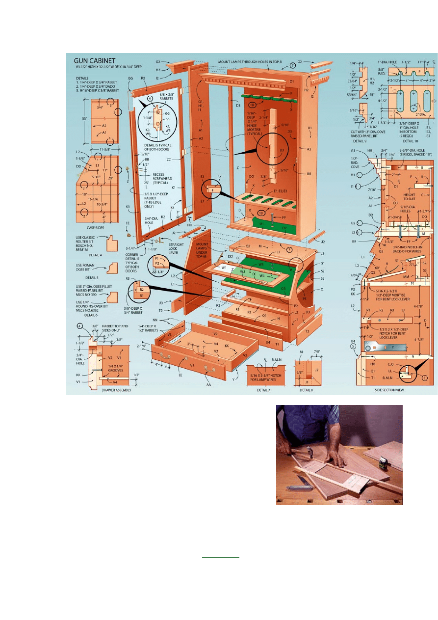
Case Construction
The gun cabinet is really two separate cases built
from cherry plywood. To make each case look like
it is built from solid lumber, edge bands are glued
to the front edge of each case panel. The drawer
fronts and doorframes are solid cherry.
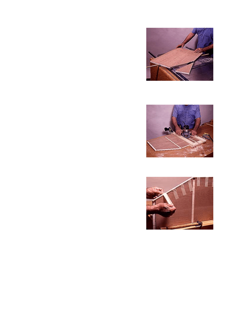
The first step in case construction is to rough cut
the plywood into smaller panels that you then cut
to finished size on a table saw. The rough cut is
made with a circular saw. Be sure to position the
plywood so that the surface that will become the
outside is facing down.
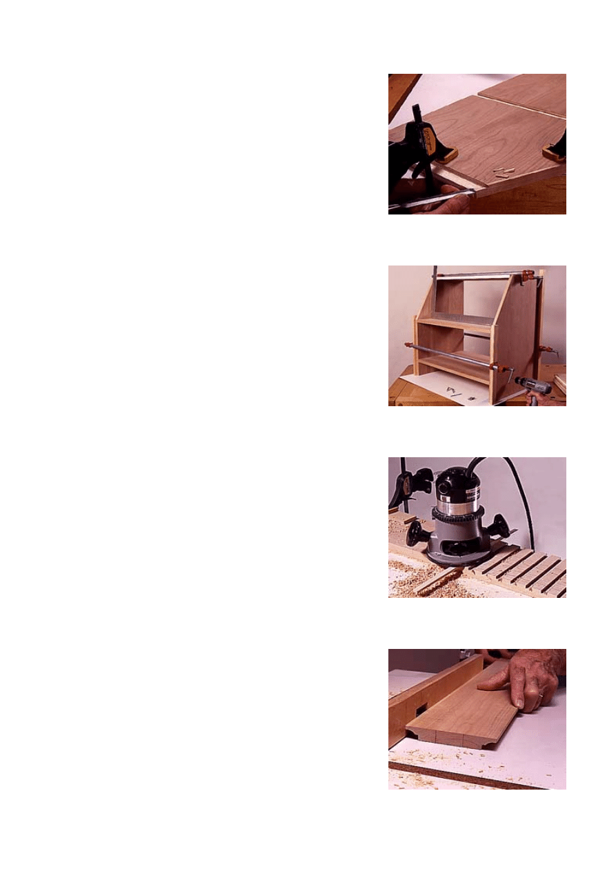
The finished cuts are made on the
. To
1--Use a strip of wood and a pair of blocks
to position the guide strip on the case
side. Nail the strip to the panel.
make the angled cuts on the lower case pieces,
take each rough-cut panel and nail a 3/8 x 3/4 x
24-in.-long tack strip to it as a guide. The tack
strip rides in the saw's miter gauge slot. To
position the tack strip accurately, first nail a
positioning strip to the panel and then butt spacer
blocks to it. Butt the tack strip to the blocks, and
nail it in place (Photo 1). Slide the tack strip into
the miter gauge slot, and feed the panel through
the blade (Photo 2).
The next step is to cut the dadoes and rabbets in
the case panels with a router and straight bit.
When cutting the dadoes for the horizontal
panels, be sure to use a 23/32-in. straight bit
because this is the actual thickness of 3/4-in.
plywood.
Mark the position of the dadoes on each side
panel and make a dado jig to guide the router.
Note that the jig uses a pair of guide rails that are
spaced apart by a distance equal to the router's
width. The two guide rails are fastened with
crossrails at either end, and these are positioned
so the panel slides snugly between them. Use the
router and the panel to position the rails. To cut
the dadoes, clamp the jig in place and run the
router right through the crossrails at either end
(Photo 3). This ensures a nice clean cut with no
tearout at either end of the dado and a dado of
the exact width needed.
Next, use a smooth-cutting blade to rip the edge
strips. Cut them to finished length, apply glue to
them and the panel edges, and then hold them in
place with masking tape (Photo 4). Drive a tiny
1/2-in. 20-ga. brad near the end of each strip to
help hold it in place. When the glue has dried,
carefully plane the strips flush to the panel's
surface, and use a chisel to cut the strip away at
the top corner of the lower case (Photo 5).
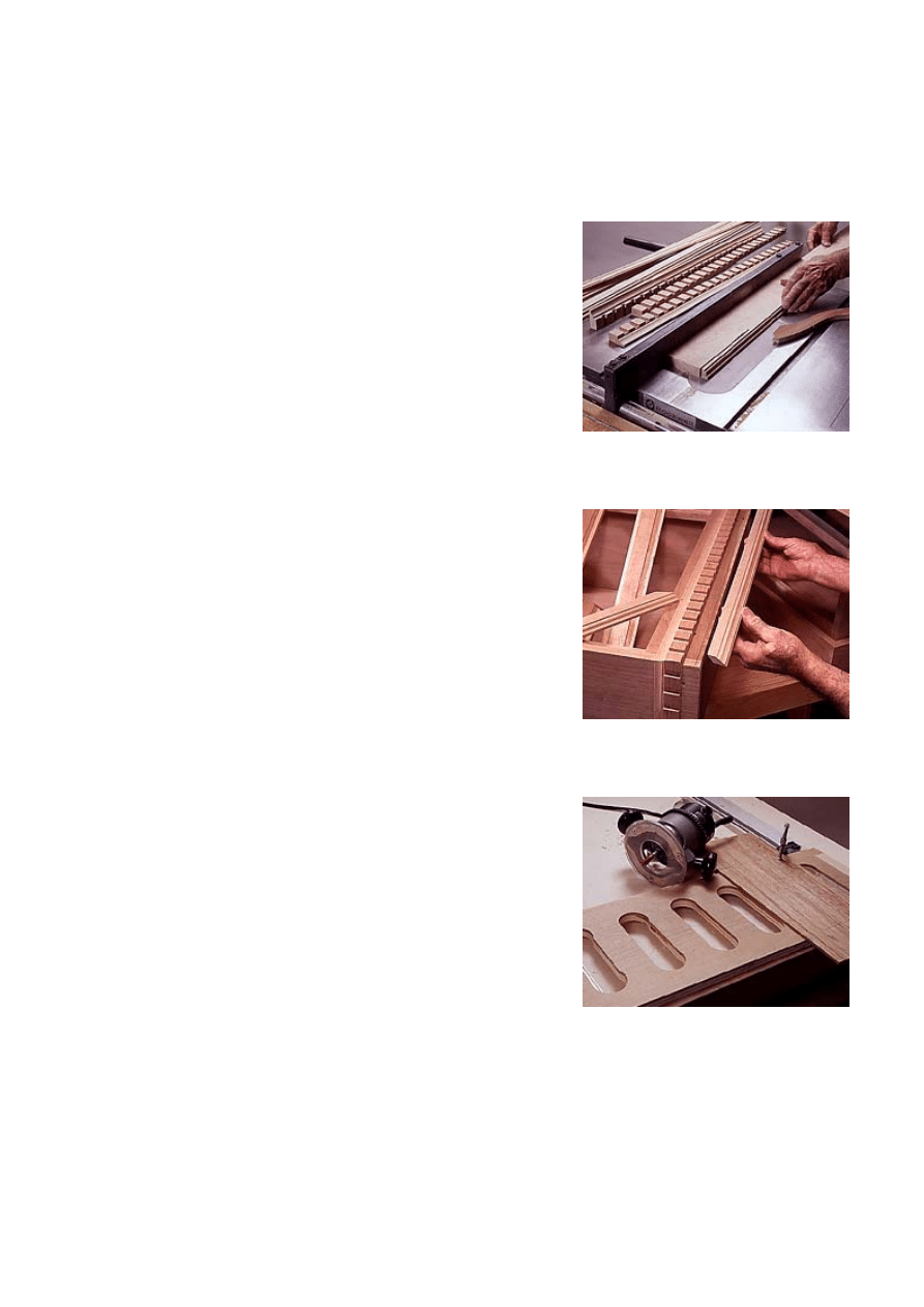
Before assembling the case, remember to bore
holes for the low-voltage lighting in the horizontal
panels of the upper case. Also, make the
crossrails for the upper case. The upper case
sides, crossrails and horizontal panels are glued
and clamped together. Drive screws through the
case sides and into the horizontal panels. Do the
same with the lower case--in both instances the
2--To cut the angle on each side panel,
slide the guide strip in the miter gauge
groove and push the panel through the
blade.
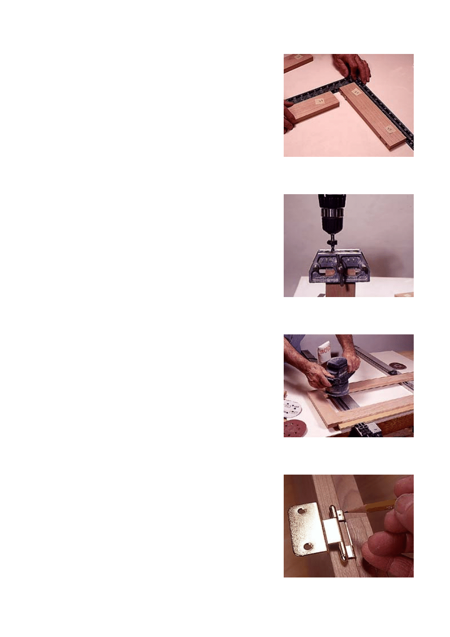
3--Use a router with a straight bit and a
parallel fence jig to cut the rabbets and
dadoes in the case sides.
4--The edge banding is glued, and held in
place using masking tape. A pair of brads
in each band keeps it from slipping.
screws will be hidden by the moldings. Mark, cut
and install the stiffeners in the upper case. Note
that the stiffeners are notched behind the top rail
and the left one is mortised to clear the hinge leaf.
Cut and temporarily install the back panel, and
then cut the shallow wiring recess in the top
horizontal panel.
Glue, clamp and screw the lower case sides to
the horizontal panels (Photo 6). Next, attach the
beveled upper and lower middle rails with glue
and screws. Note that the drawer divider is not
permanently installed in the lower case until after
the drawers are mounted and the locks are
installed in the drawer fronts.
Moldings
The cabinet's dentil molding is made with a router
and a 1/2-in.-dia. straight bit. Bolt a fence to the
router's base 53/64 in. from the bit. Rip the
molding stock and joint its edges so they are
parallel and the ends square. Make the first dado
cut, move the fence into the groove, make the
second cut and continue on in this fashion until
the molding is complete (Photo 7). Make several
passes on the router table to cut the thumbnail
molding on the dentil's lower edge (Photo 8).
5--The edge banding blocks the rabbet at
the top of the lower case. Use a chisel to
pare away the edge band at this point.
6--Glue and clamp the case sides to the
horizontal panels and drive screws into
the upper and lower panels.
7--The dentil molding is cut using a router
with a guide strip screwed to its base. The
strip rides in the previously cut dado.
8--Cut the molding on the lower edge of
the dentil molding using a router table and
a cove raised-panel bit.
Cut the rest of the moldings for the cabinet on the
router table, then rip them off on the table saw
(Photo 9).
Attach the moldings to the case, beginning with
the dentil. Clamp it in place, and mark its miters.
Bore pilot holes in it for alignment nails. Glue and
clamp the molding and drive the nails through it.
Attach the side dentil moldings in the same
sequence.
To apply the ogee molding above the dentil,
follow the same sequence, but don't nail the
molding to the case. Attach it to the dentil molding
with nails from above (Photo 10).
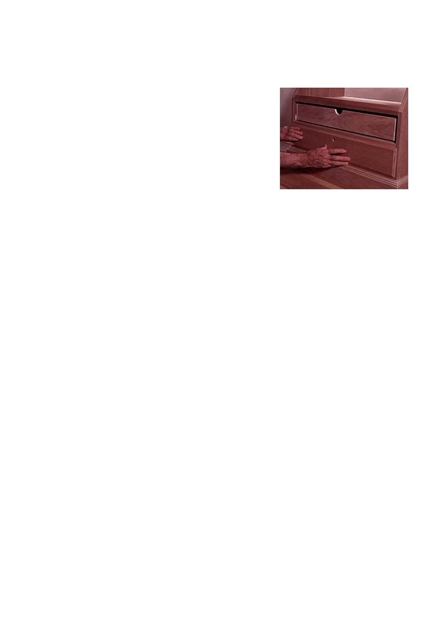
Supports, Doors, Drawers And Lighting
Make the butt-rest panel, then bore 2-in.-dia.
holes in it, and saw out the waste between them.
Trim the cutouts using a router and flush-trimming
bit. Run the router against a plywood fence
clamped to the panel (Photo 11).
Cut out the barrel rest, bore a series of 1-in.-dia.
holes in it, and make a series of cuts tangent to
the holes using a sabre saw. Make the pistol
platform, cover it with felt and leave it aside to be
installed after the cabinet is finished.
Next, rip and crosscut the door rails and stiles.
Mark the centerlines on the pieces, and use a
dowel jig to bore holes in either the rails or the
stiles. Insert dowel centers in the holes and align
the parts using a framing square. Press the parts
together (Photo 12), and use a dowel jig to bore
holes on the marks (Photo 13). Insert dowels in
the holes, then glue and clamp the assembly.
Sand the doors using a random-orbit oscillating
sander (Photo 14).
Cut the glazing rabbets inside the doors, and cut
the molded edges on them. Cut the door's glazing
strips, and round the strip ends to fit the rabbets.
Buy acrylic glazing cut to size, then sand the
glazing s corners to fit the rabbets. Install the
9--Cut the ogee moldings on the edge of a
wide board, then rip the molding off the
board on the table saw.
10--The ogee molding above the dentil is
held in place with glue, and nails driven
into the molding below.
11--Smooth the slots in the butt rest using
a flush-trimming bit and a router. Run the
router along a fence clamped in place.
glazing after the case is finished.
Now, lay the upper and lower cases on their
backs, and temporarily install the door hinges.
Lay each door in place over the hinge. Press
down on the door, so that a small dimple on the
hinge marks the hinge's position on the door
(Photo 15). Remove the door, and lay it on the
workbench. Position a hinge on the dents and use
the hinge as a template to bore the screwholes.
Rip, crosscut and joint the drawer parts, then cut
the rabbets and grooves in the parts. Also cut a
half circle in each drawer box for lock clearance.
Glue and clamp the drawer boxes. Make the
drawer fronts and bore a lock hole in each.
Install the drawer slides in the case per the
manufacturer's directions. Mount each drawer box
in its slides and drive four drywall screws through
each drawer front. Hold the drawer front in front of
the drawer boxes and press the drawer front
against the drywall screws to mark the drawer
front location on the box (Photo 16). Bore pilot
holes on the marks, mount the locks on the
drawer fronts, and install the drawer fronts.
Mark the location of the lock cam levers on the
drawer divider and on the bottom of the pistol
compartment shelf. Remove the divider and shelf,
and then cut the mortises to accommodate the
lock cam lever. Reinstall the divider.
Now stack the cases, clamp them together and
bore holes for the connecting bolts. Bolt the two
cases together and carefully finish-sand. We
applied two coats of Watco Cherry Danish Oil
Finish, followed by two coats of semigloss
polyurethane. The finish was applied on the
doors, drawers and case assembly separately.
Install these components after you are through
applying finish on them. The pistol compartment
shelf, the glazing in the doors, the gun supports
and the plywood back panels are installed after
finishing.
The final touch is to install two 3-light, 20-watt
halogen Combilight kits. The product is sold at
home centers and lighting showrooms. To locate
a distributor, contact Lusa Lighting, 26235
12--With dowel centers inserted, press the
door parts together while aligning them
with a framing square.
13--Use the marks created by the dowel
centers to position the dowel jig. Bore the
remaining dowel holes.
14--Sanding door rails and stiles can be
tricky. Use a random-orbit oscillating
sander to avoid crossgrain sanding.
Technology Dr., Valencia, CA 91355; 800-779-
2946.
15--Small dimples on the hinges will mark
the location of the screwholes when the
door is pressed on top of them.
16--Press each drawer face onto its
drawer box. Four screws driven through
the box make registration marks on the
drawer face.
Wyszukiwarka
Podobne podstrony:
Cabinet Gun Cabinet ( Part 1)
Cabinet Gun Cabinet (Part 2)
Corner Buffet Cabinet(1)
cabinetmakerupho00sher
Corner Cabinet 1
Plan and Install Kitchen Cabinets
bathroom cabinet szafka lazienkowa
Brydcliffe Cabinet
Display Cabinet 2
box taurus cabinets manual
Display Cabinet 3
Atlantic E New IP66 Cabinet id Nieznany
Mobile File Cabinet
I Ogólnopolski Kongres Naukowo Szkoleniowy CABINES Polska ~Dermatologia w kosmetyce i kosmetologii~
constitution of cabinet commitee on uidai 2009
Kitchen Base Cabinet
Corner Buffet Cabinet(1)
Cabinet Compact TV Cabinet
Cabinet Kitchen Island
więcej podobnych podstron