
28-1
Ignition system, checking
General notes on ignition system
Always switch off the ignition before connecting
or disconnecting the battery, otherwise the
engine control module may be damaged.
The engine control module is equipped with On
Board Diagnostic (OBD).
For trouble-free operation of the electrical
components a voltage of at least 11.5 V is
necessary.
During some of the tests it is possible that the
control module will detect and record a
malfunction. The DTC memory must therefore
be checked and if necessary erased when all
tests and repair work have been completed.
After completing troubleshooting, repairs or
component tests, it is possible that the engine
will start, run for a short period and then cut out.
If this happens it may be that the immobilizer is
blocking the engine control module. In such
cases the DTC memory must be checked and if
necessary the control module must be adapted.
Page 1 of 82
Ignition system, checking
1/17/2006
http://127.0.0.1:8080/audi/servlet/Display?action=Goto&type=repair&id=AUDI.C5.FU03.28.1.66.14

28-2
Safety precautions
To prevent injuries to persons and/or damage to
the fuel injection and ignition system, the
following must be noted:
WARNING!
Be alert when working on or near the engine.
High ignition secondary voltage can cause
serious personal injury and damage vehicle
components.
DO NOT touch or disconnect ignition wiring
when the engine is running or being turned
at starter speed.
DO NOT operate the starter if fuel injectors
are removed.
Always switch off the ignition before
connecting or disconnecting the battery,
otherwise the engine control module may be
damaged.
The ignition must be switched off before
connecting or disconnecting injection or
ignition system wiring or tester cables.
In order to run the engine at starting speed
Page 2 of 82
Ignition system, checking
1/17/2006
http://127.0.0.1:8080/audi/servlet/Display?action=Goto&type=repair&id=AUDI.C5.FU03.28.1.66.14

without actually starting it (e.g. to test
compression), disconnect the connectors
from the output stages of the ignition coils
and from all the fuel injectors. After
completing the work, check and erase the
DTC memory.
The ignition must always be switched off
when cleaning the engine.
Page 3 of 82
Ignition system, checking
1/17/2006
http://127.0.0.1:8080/audi/servlet/Display?action=Goto&type=repair&id=AUDI.C5.FU03.28.1.66.14

28-3
CAUTION!
Before disconnecting the battery:
Stop the engine.
Be sure of proper radio code (for vehicles
equipped with coded anti-theft radio).
When connecting and disconnecting
electrical test equipment (LED voltage tester,
multimeter, etc.):
Be sure the ignition is switched OFF.
Use correct adapters from VAG1594
connector test kit
Page 4 of 82
Ignition system, checking
1/17/2006
http://127.0.0.1:8080/audi/servlet/Display?action=Goto&type=repair&id=AUDI.C5.FU03.28.1.66.14
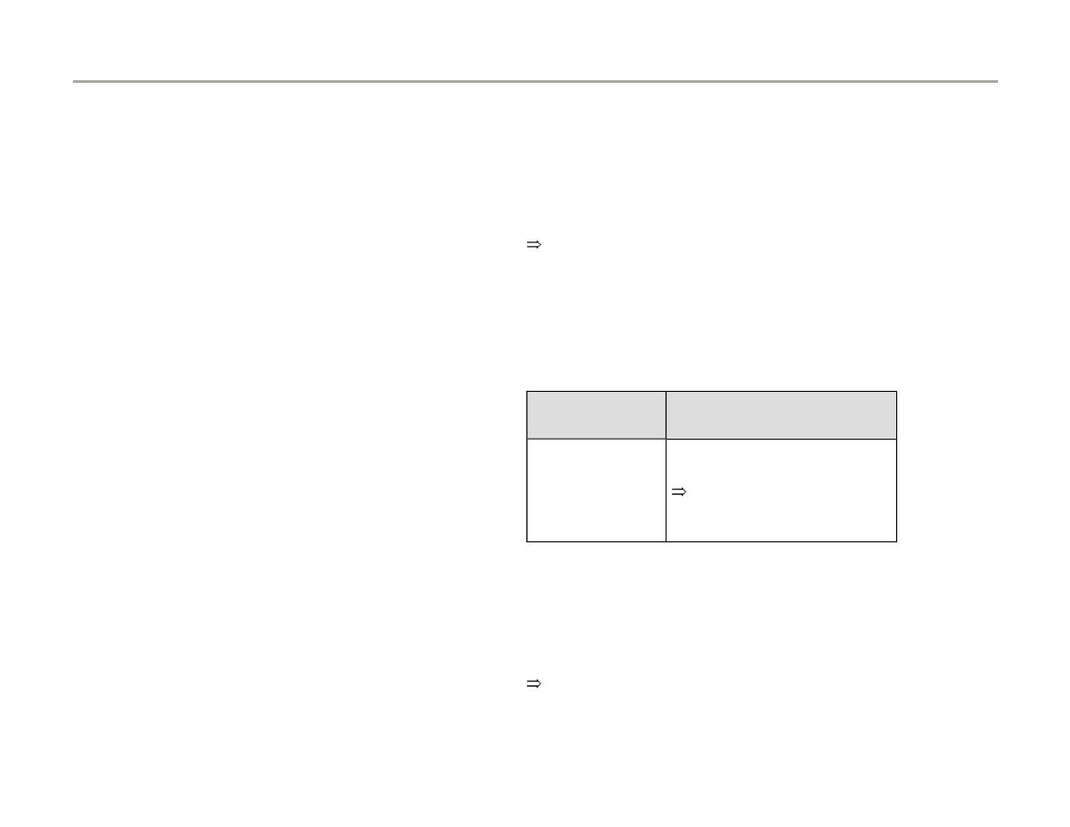
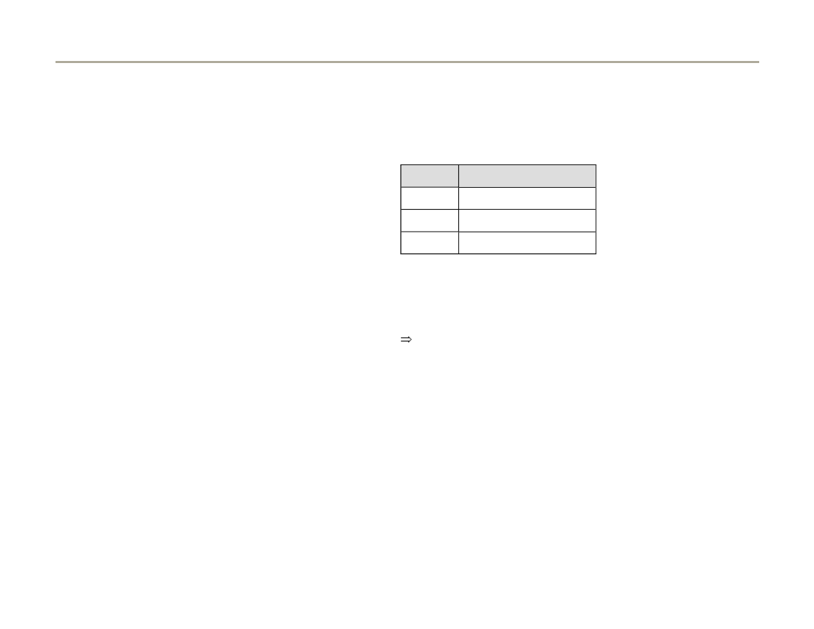
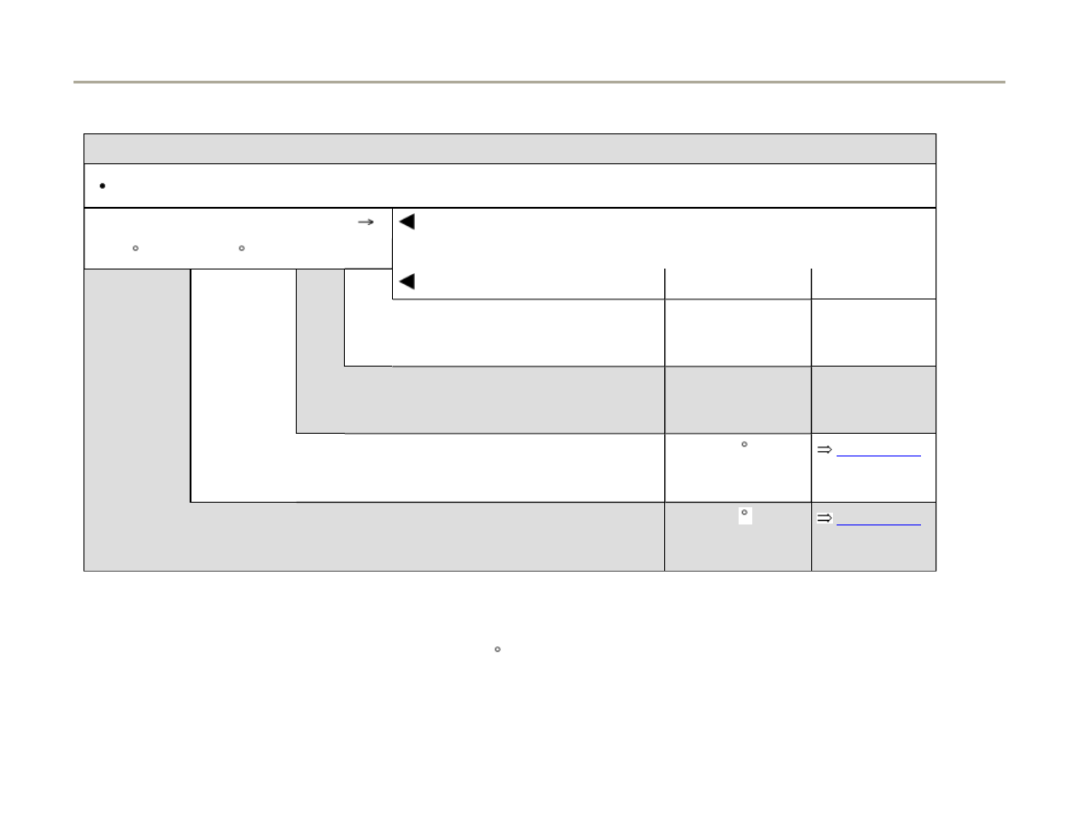
28-4
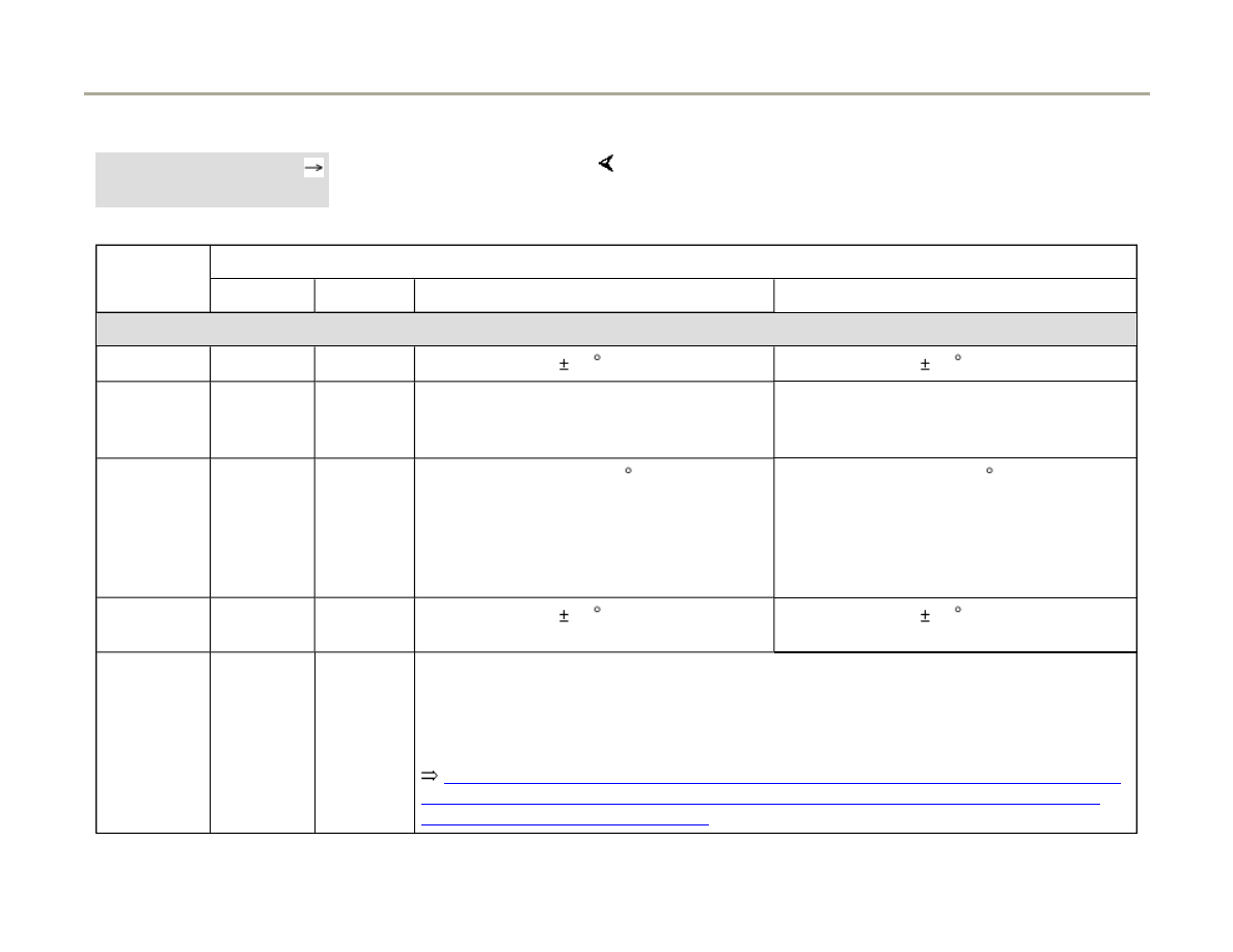
Technical data, ignition system
Engine code
APB (TLEV engine)
BEL (LEV engine)
Engine idle RPM
Not adjustable -
controlled by Idle Air
Control (IAC)
650 - 750 RPM
RPM limit
Operates by closing
throttle valve
Operates by shutting
off fuel injectors
approx. 6800 RPM
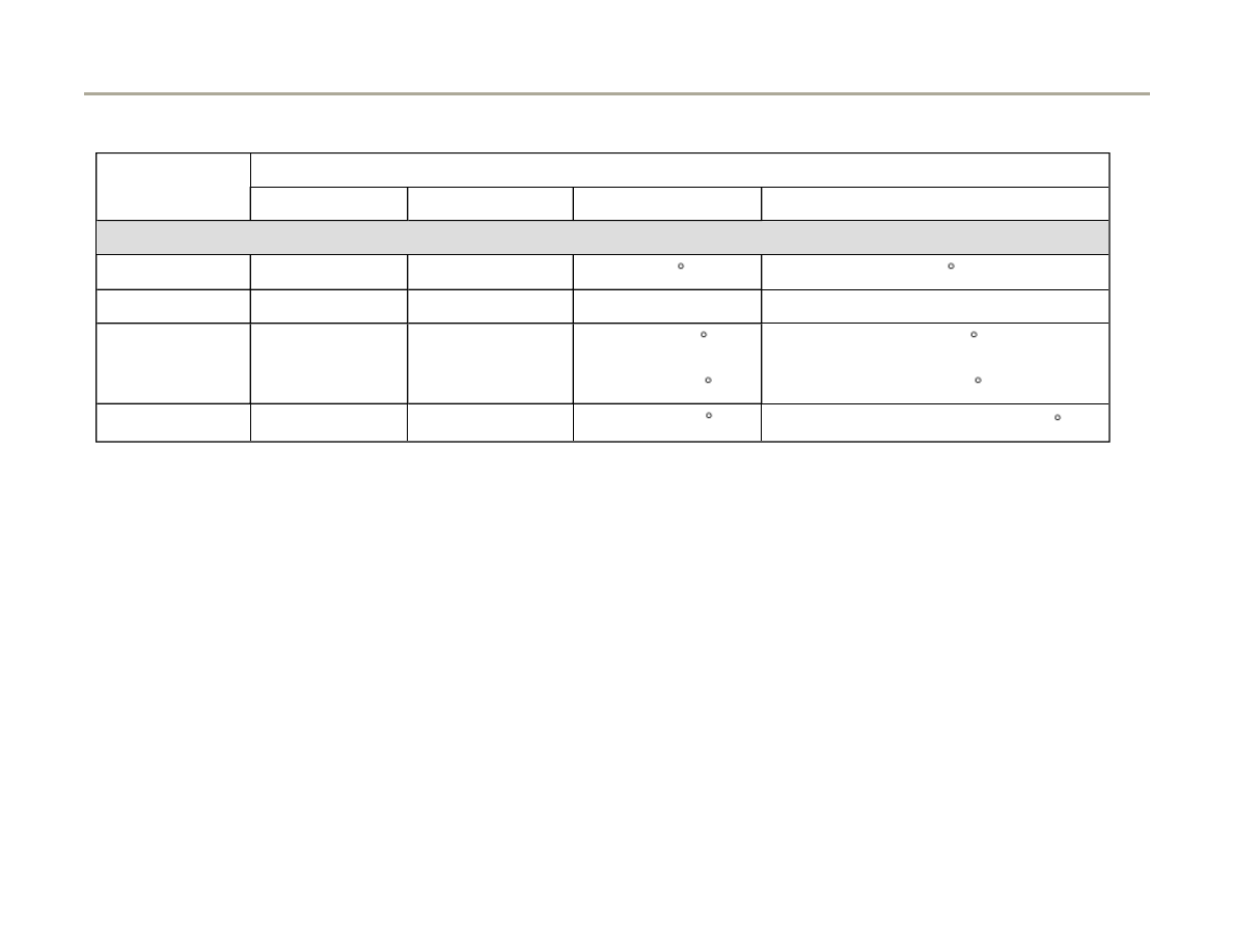
Ignition timing is
determined by the control
module.
Ignition timing cannot be
adjusted.
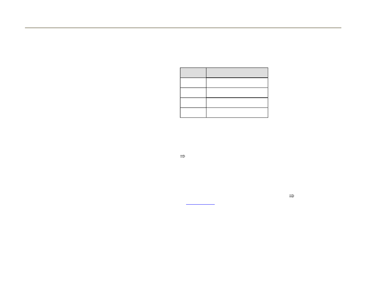
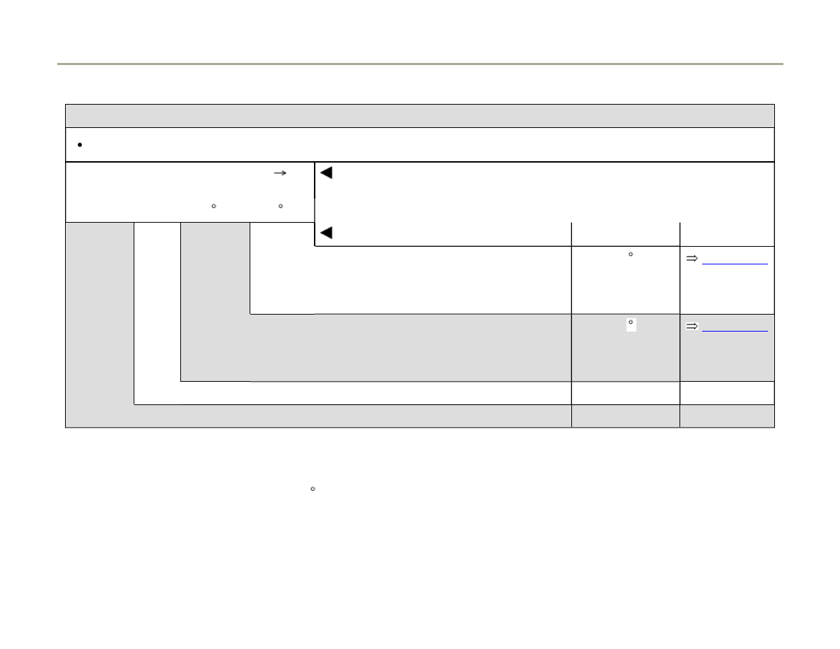
Ignition system
Single-coil system with 6 ignition coils located above spark plug connectors and installed directly
on spark plugs. On
PB engine power output stages are located as separate components in
air cleaner housing. On BELengine power output stages are integrated into ignition coils.
Spark plugs
connectors
Resistance approx.: 2k Ohm
Page 5 of 82
Ignition system, checking
1/17/2006
http://127.0.0.1:8080/audi/servlet/Display?action=Goto&type=repair&id=AUDI.C5.FU03.28.1.66.14

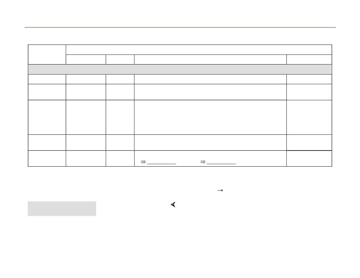
Firing order
1-4-3-6-2-5
Page 6 of 82
Ignition system, checking
1/17/2006
http://127.0.0.1:8080/audi/servlet/Display?action=Goto&type=repair&id=AUDI.C5.FU03.28.1.66.14

28-5
Ignition coils, checking
Note:
The following procedure is for vehicles with
engine code APB. The procedure for vehicles
with engine code BEL is on
Page 28-11
.
Misfiring is recognized by the On Board
Diagnostic (OBD). This means a non-working
cylinder is stored with the cylinder number in
the DTC memory. This has an advantage in
case of a malfunction the trouble shooting
procedure can be started at a certain cylinder.
Check the DTC memory of the Engine Control
Module (ECM) before commencing trouble
shooting.
Test conditions
No DTCs stored relating to any of the fuel
injectors
Determine a non-working or misfiring cylinder as
follows:
Page 7 of 82
Ignition system, checking
1/17/2006
http://127.0.0.1:8080/audi/servlet/Display?action=Goto&type=repair&id=AUDI.C5.FU03.28.1.66.14

28-6
- With engine running disconnect harness
connectors in sequence from fuel injectors, and
observe engine performance.
or
- Compare spark plugs of all cylinders with each
other and check for soot on electrodes.
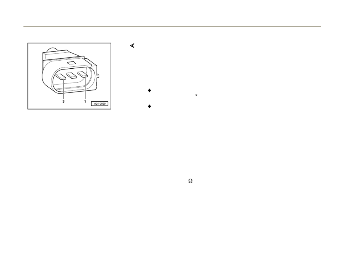
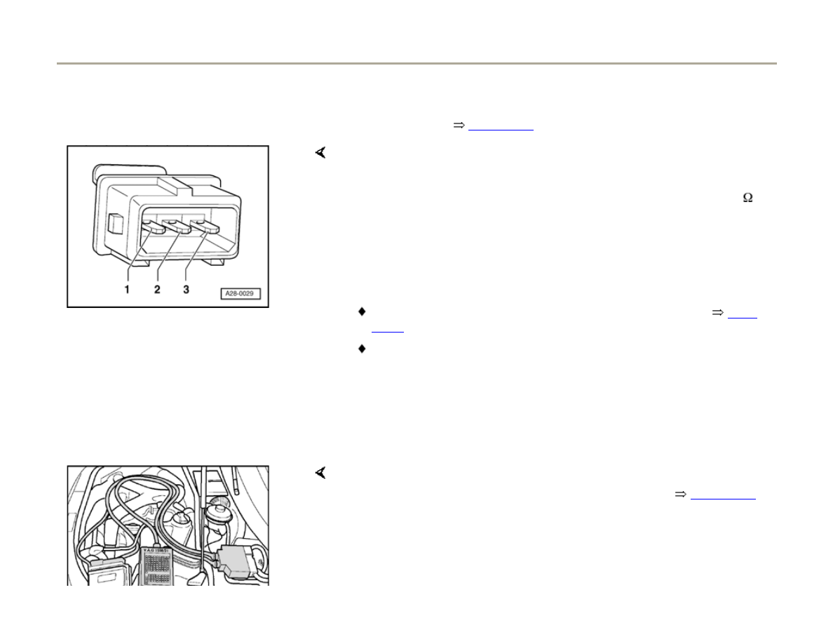
When the faulty cylinder has been identified:
- Connect hand-held multimeter (resistance
measurement) to spark plug connector:
Note:
The spark plug connector can be disconnected
from the ignition coil.
Specification: approx.: 2k Ohm.
Page 8 of 82
Ignition system, checking
1/17/2006
http://127.0.0.1:8080/audi/servlet/Display?action=Goto&type=repair&id=AUDI.C5.FU03.28.1.66.14

28-7
If specification is not obtained:
- Replace spark plug connector.
If specification is obtained:
- Exchange spark plug from faulty (misfiring)
cylinder with one from another cylinder. Visually
check spark plug for damage, e.g. cracks on
ceramic body of spark plug.
- If malfunction (misfire) occurs now on other
cylinder, replace spark plug.
If the malfunction remains at the same cylinder:
- Exchange ignition coil from faulty (misfiring)
cylinder with one from another cylinder. Visually
check ignition coil for damage (ignition coil could
be cracked or bursted)
- If malfunction occurs now on other cylinder,
replace ignition coil.
Page 9 of 82
Ignition system, checking
1/17/2006
http://127.0.0.1:8080/audi/servlet/Display?action=Goto&type=repair&id=AUDI.C5.FU03.28.1.66.14
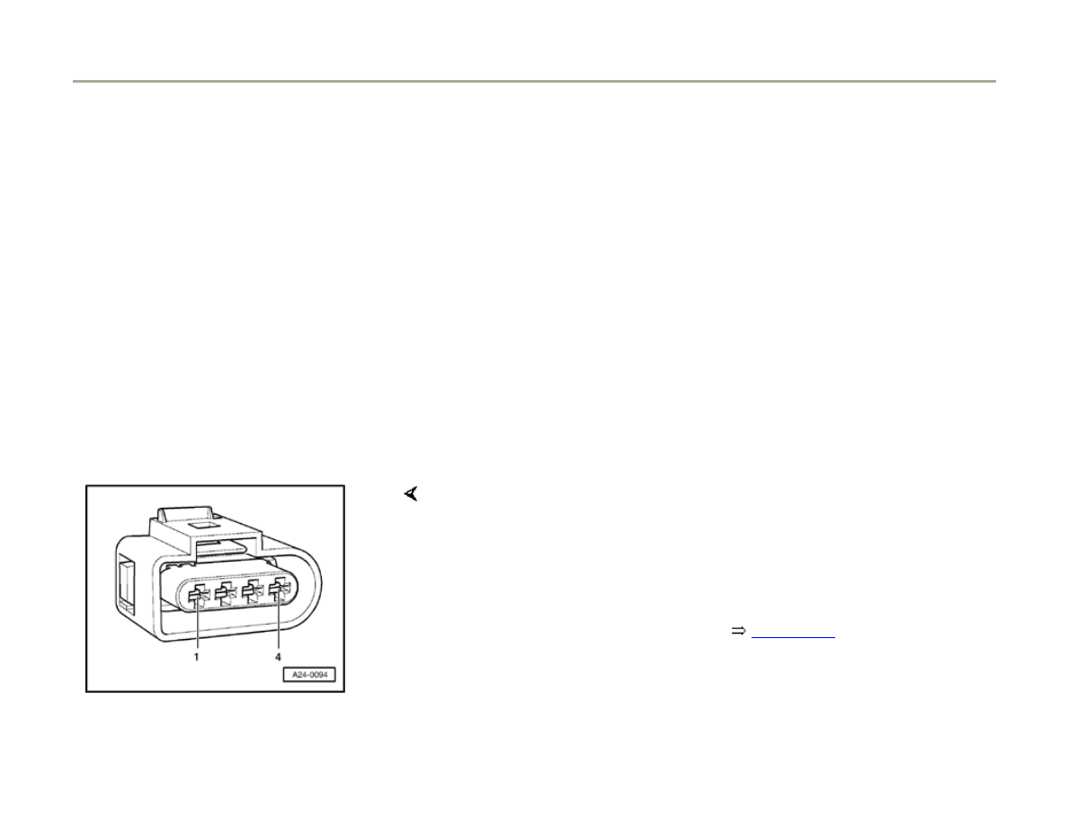
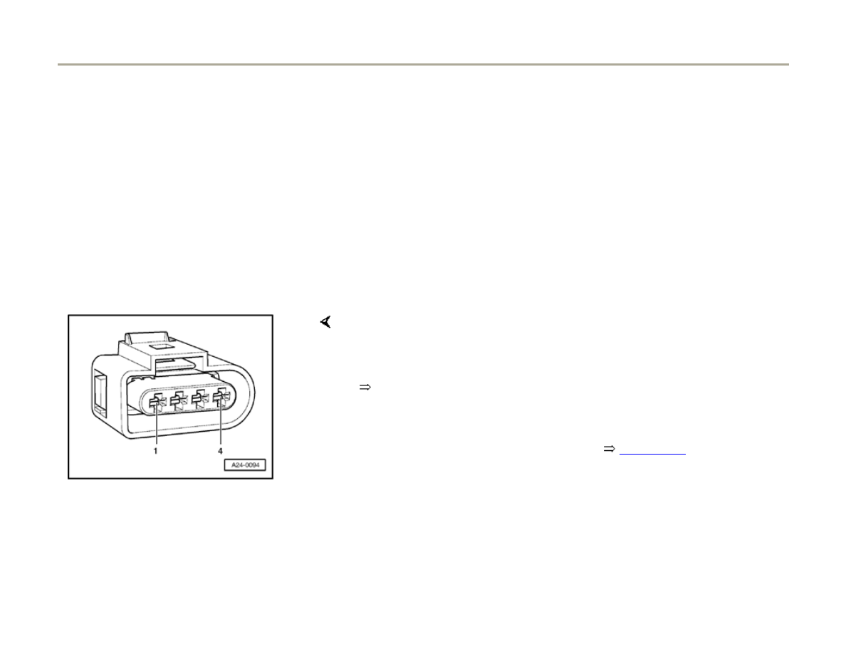
28-8
If malfunction remains at the same cylinder.
- Disconnect harness connector from ignition
coil.
Electrical Wiring Diagrams, Troubleshooting & Component Locations
If the Ground (GND) connection is OK.
- Check Ground (GND) connection between socket 4a and engine
Ground (GND) for open circuit and short circuit to B+.
- Repair any open/short circuit as necessary.
- Connect hand-held multimeter (voltage range) to terminal 15 of
harness connector and Ground (GND).
- Disconnect harness connector from fuel injector of cylinder to be
tested.
- Operate starter.
Specification: approx. battery voltage
Page 10 of 82
Ignition system, checking
1/17/2006
http://127.0.0.1:8080/audi/servlet/Display?action=Goto&type=repair&id=AUDI.C5.FU03.28.1.66.14
28-9
If the specification is not obtained:
- Check wiring.
Electrical Wiring Diagrams, Troubleshooting &
Component Locations
If the specification is obtained:
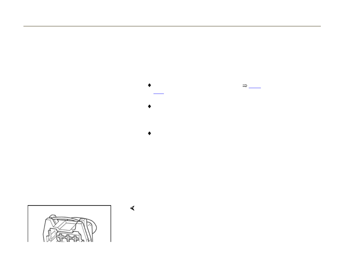
- Disconnect 3-pin harness connectors on power
output stages for ignition coils; component
locations overview
Page 24-5
.
- Connect LED voltage tester to 3-pin connectors
for both output stages.
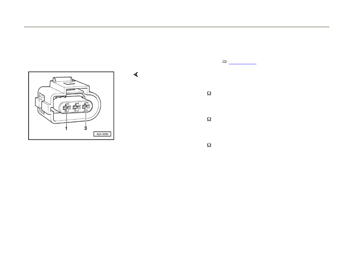
If the specifications are not obtained:
- Connect LED voltage tester VAG1527 to following contacts on
connectors for power output stages:
3-pin harness connector
terminal
Specification
(with starter activated)
1 + Ground (GND)
LED voltage tester must
2 + Ground (GND)
light up
3 + Ground (GND)
Page 11 of 82
Ignition system, checking
1/17/2006
http://127.0.0.1:8080/audi/servlet/Display?action=Goto&type=repair&id=AUDI.C5.FU03.28.1.66.14

- Switch ignition off.
Page 12 of 82
Ignition system, checking
1/17/2006
http://127.0.0.1:8080/audi/servlet/Display?action=Goto&type=repair&id=AUDI.C5.FU03.28.1.66.14
28-10
- Check following wiring connections for open circuits and/or short to B+
or Ground (GND).
Black 3-pin connector on power
output stage, terminal
3-pin connector on ignition
coil, terminal
1
1 (cylinder 1)
2
1 (cylinder 2)
3
1 (cylinder 3)
- Check following wiring connections for open circuits and/or short to B+
or Ground (GND).
Brown 3-pin connector on power
output stage, terminal
3-pin connector on ignition
coil, terminal
1
1 (cylinder 4)
2
1 (cylinder 5)
3
1 (cylinder 6)
- Eliminate any open/short circuit as necessary.
Page 13 of 82
Ignition system, checking
1/17/2006
http://127.0.0.1:8080/audi/servlet/Display?action=Goto&type=repair&id=AUDI.C5.FU03.28.1.66.14

28-11
Ignition coils, checking, Engine code BEL
Note:
The ignition coil and the power output stage are
integrated in one component.
Requirements
No DTCs stored relating to any of the fuel
injectors
Determine a non-functional or misfiring cylinder
as follows:
- Check misfire recognition,
Page 28-66
If a misfire is recognized:
- Continue with cylinder displayed using test "If a
misfire is recognized".
If no misfire is recognized:
- With engine running, disconnect connectors
from injectors one at a time and observe how
engine is running.
Page 14 of 82
Ignition system, checking
1/17/2006
http://127.0.0.1:8080/audi/servlet/Display?action=Goto&type=repair&id=AUDI.C5.FU03.28.1.66.14

28-12
or
- Compare spark plugs of all cylinders with each
other and look for corroded electrodes.
If the faulty cylinder is found:
- Exchange spark plug from faulty cylinder with
one from another cylinder.
If problem cylinder moves with the spark plug:
- Replace spark plug.
Page 15 of 82
Ignition system, checking
1/17/2006
http://127.0.0.1:8080/audi/servlet/Display?action=Goto&type=repair&id=AUDI.C5.FU03.28.1.66.14
28-13
If the fault remains with the cylinder:
- Exchange ignition coil from faulty cylinder with
one from another cylinder.
- If fault now appears in another cylinder, replace
ignition coil.
If the fault remains with the cylinder:
- Check Ground wiring of ignition coil.
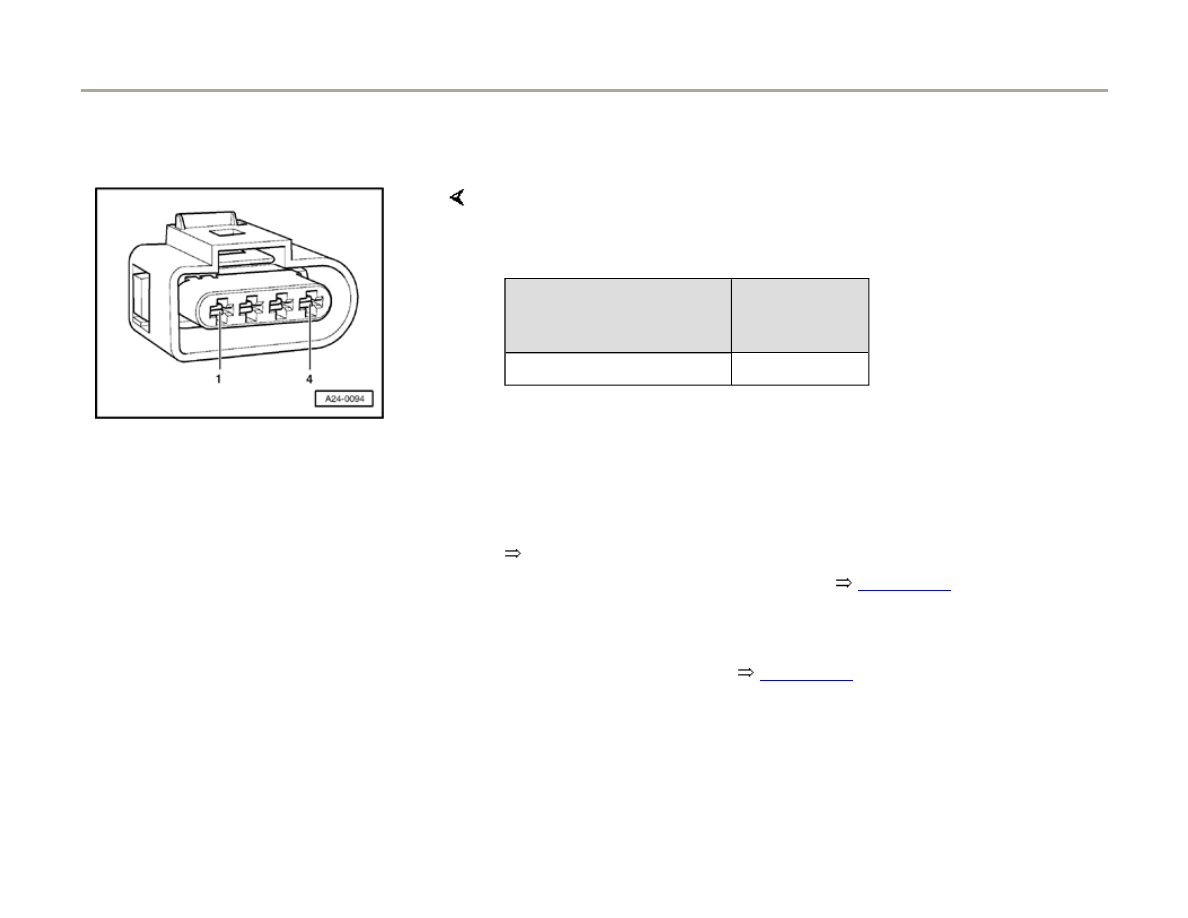
Checking Ground wiring of ignition coil
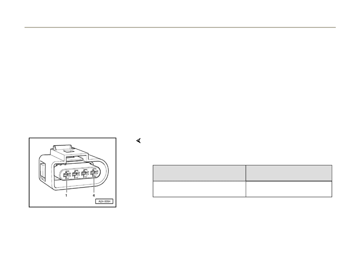
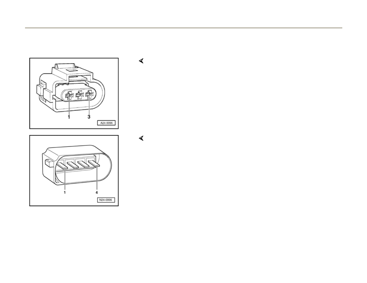
- Disconnect 4-pin connector on respective
ignition coil.
If Ground wiring is OK:
- Check Ground wiring on socket 4 of 4-pin connector after engine
Ground for open circuit or short circuit to B+.
- Eliminate any open or short circuits.
- Check voltage supply to ignition coil
Page 28-14
.
Page 16 of 82
Ignition system, checking
1/17/2006
http://127.0.0.1:8080/audi/servlet/Display?action=Goto&type=repair&id=AUDI.C5.FU03.28.1.66.14
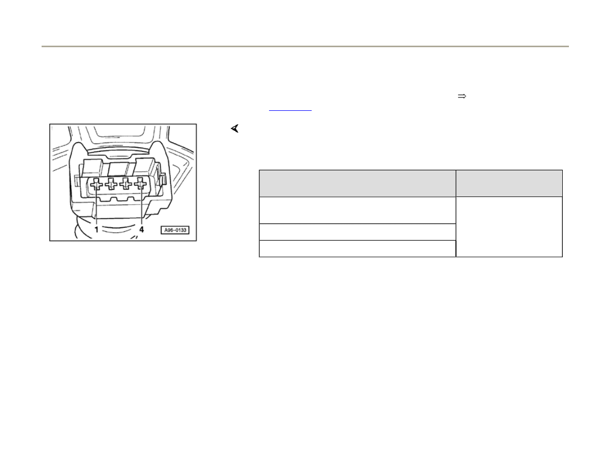
28-14
Checking voltage supply of the ignition coils
Specified value: approx. battery voltage
If the specified value is not attained:
Electrical Wiring Diagrams, Troubleshooting & Component Locations
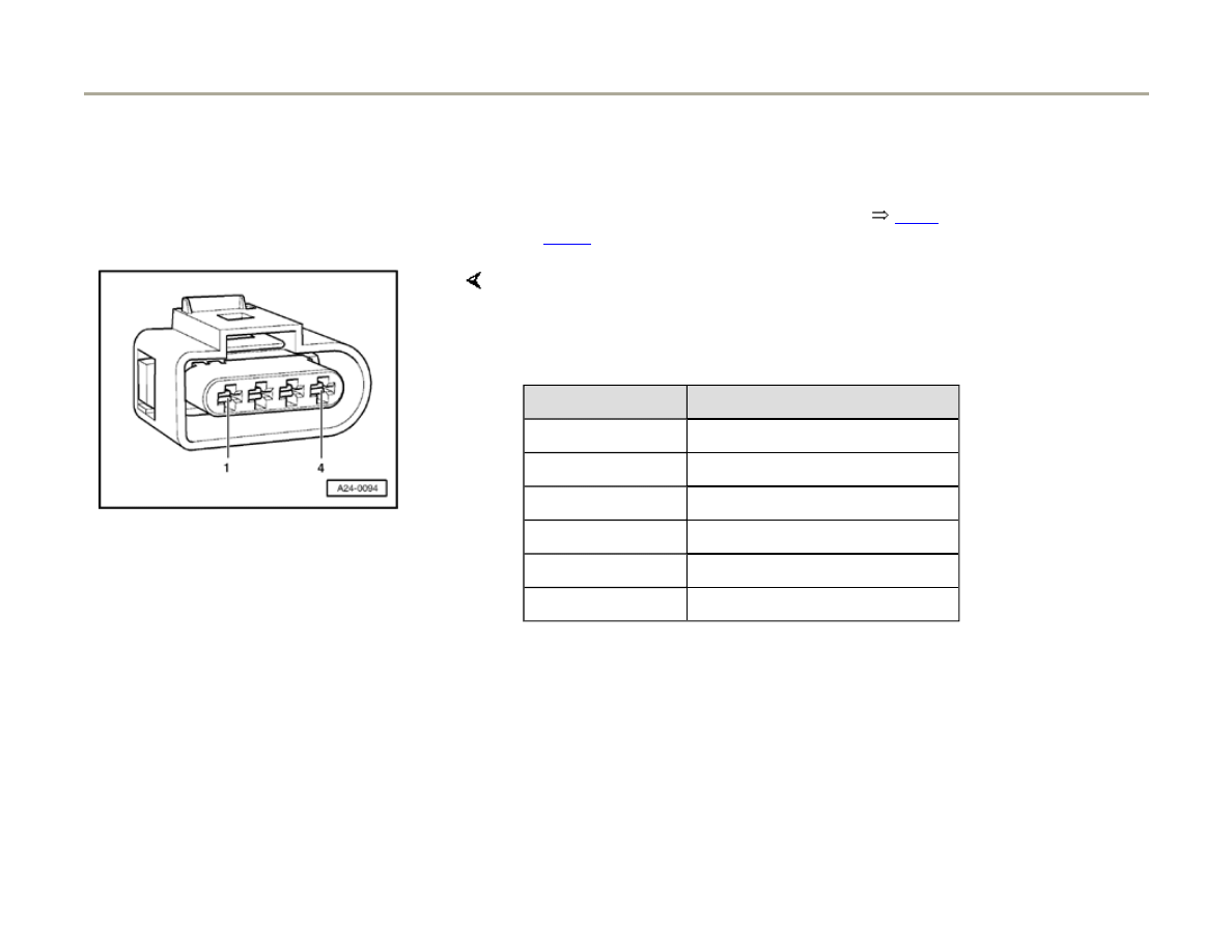
If the specification is not obtained:
- Connect multimeter for measuring voltage to following sockets on
connector:
- Switch ignition on.
4-pin harness connector
terminal
Specification
1 + Ground (GND)
Battery voltage
- Check wiring connection for socket 1 via fuse to Motronic (ECM) power
supply relay -J271- for continuity and repair if necessary.
- Check ECM power supply relay -J271-
Page 28-24
.
- Check power output stage
Page 28-15
.
Page 17 of 82
Ignition system, checking
1/17/2006
http://127.0.0.1:8080/audi/servlet/Display?action=Goto&type=repair&id=AUDI.C5.FU03.28.1.66.14

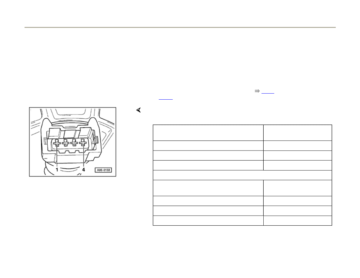
28-15
Power output stages for ignition coils,
checking
Note:
The following procedure is for vehicles with
engine code APB. The procedure for vehicles
with engine code BEL is on
Page 28-20
.
Power Output Stage -N122- (black connector)
activates the ignition coils for cylinder bank 1
(cylinders 1 to 3).
Power Output Stage 2 -N192- (brown
connector) activates the ignition coils for
cylinder bank 2 (cylinders 4 to 6).
Checking activation of power output stages
- Disconnect harness connectors from all six fuel
injectors.
Note:
It is important to ensure that no fuel is injected
during the test as this would damage the catalytic
converter. The harness connectors on the fuel
injectors must therefore be disconnected.
Page 18 of 82
Ignition system, checking
1/17/2006
http://127.0.0.1:8080/audi/servlet/Display?action=Goto&type=repair&id=AUDI.C5.FU03.28.1.66.14
28-16
- Disconnect 4-pin harness connectors on power
output stages Component locations overview,
Page 24-5
.
- Connect LED voltage tester VAG1527 in turn to following contacts on
two 4-pin connectors for power output stages.
- Operate starter for a few seconds.
6-pin connector on wiring harness,
terminal
Specification
1 + Ground (GND)
LED voltage tester
must
3 + Ground (GND)
flash (brief impulse)
4 + Ground (GND)
Page 19 of 82
Ignition system, checking
1/17/2006
http://127.0.0.1:8080/audi/servlet/Display?action=Goto&type=repair&id=AUDI.C5.FU03.28.1.66.14
28-17
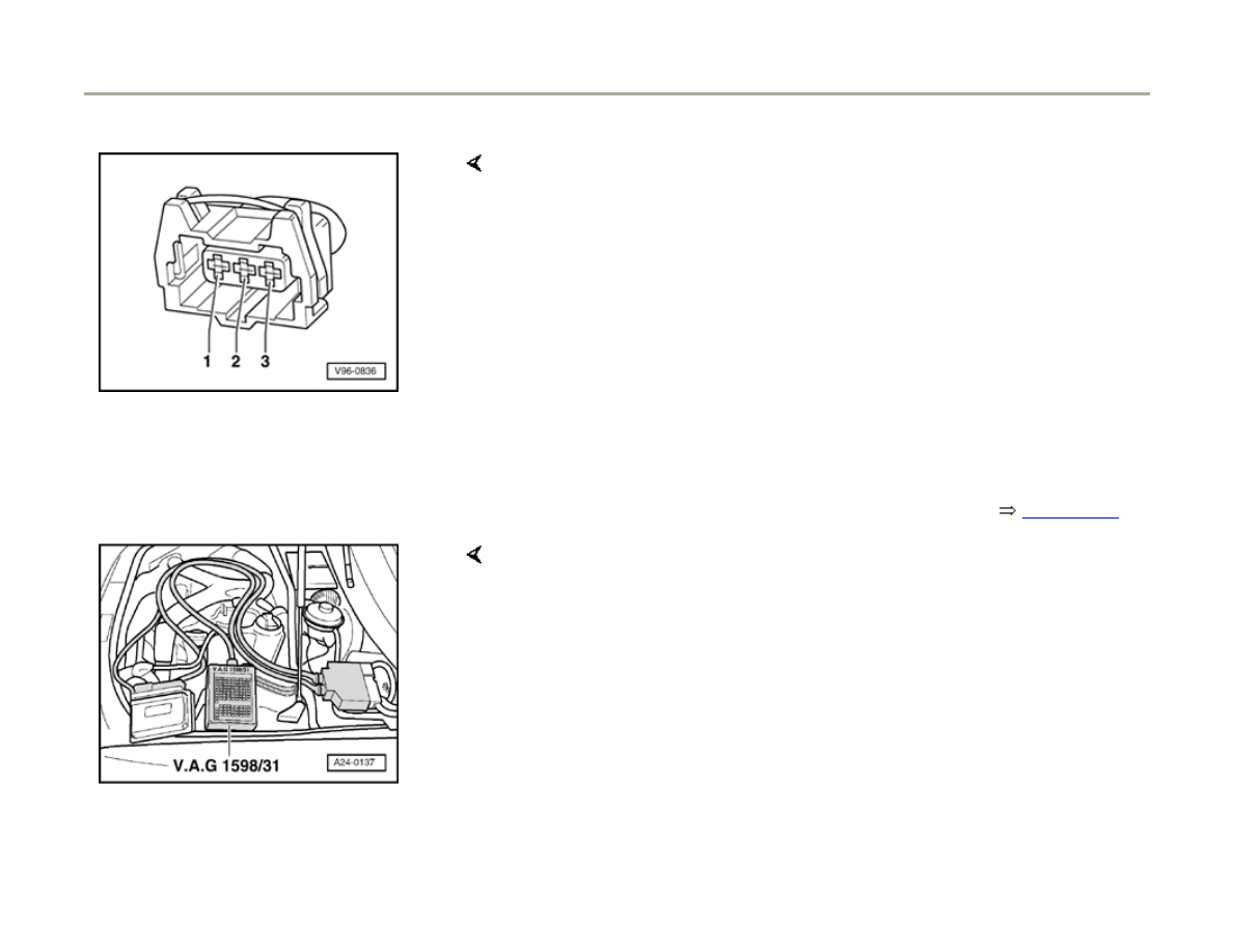
If the specifications are not obtained:
- Switch ignition off.
- Connect test box VAG 1598/31 to wiring
harness for engine control module. Do not
connect to engine control module itself.
Page
24-20
.
- Check following wiring connections for open circuits and/or short to B+
or Ground (GND):
Black 4-pin connector on wiring
harness, terminal
VAG1598/31 test box,
socket
1
94
3
110
4
102
Brown 4-pin connector on wiring
harness, terminal
VAG1598/31 test box,
socket
1
95
3
111
4
103
Page 20 of 82
Ignition system, checking
1/17/2006
http://127.0.0.1:8080/audi/servlet/Display?action=Goto&type=repair&id=AUDI.C5.FU03.28.1.66.14

28-18
- Correct any open/short circuit as necessary.
If no wiring malfunction is detected:
- Connect 4-pin connectors to power output
stages.
- Disconnect 3-pin connectors from power output
stages.
- Connect LED voltage tester VAG1527 to battery
(B+) and to one of 3 terminals on power output
stage.
- Operate starter for few seconds.
LED voltage tester should flash.
- Perform test with all 3 terminals on each of 3-pin
connectors for power output stages.
LED voltage tester should flash each time.
Page 21 of 82
Ignition system, checking
1/17/2006
http://127.0.0.1:8080/audi/servlet/Display?action=Goto&type=repair&id=AUDI.C5.FU03.28.1.66.14

28-19
If the LED voltage tester does not flash when
testing one or more of the contacts:
- Check the Ground (GND) connections for the
power output stages as follows:
- Disconnect 4-pin connector from power output
stages.
- Connect LED voltage tester VAG1527 to
battery (B+) and terminal 2 of each 4-pin
connector in turn.
LED voltage tester should light up.
If LED voltage tester does not light up,
- Test for open circuit in wiring using wiring
diagram.
Electrical Wiring Diagrams, Troubleshooting &
Component Locations
If the LED voltage tester lights up:
- Replace power output stage.
Note:
Page 22 of 82
Ignition system, checking
1/17/2006
http://127.0.0.1:8080/audi/servlet/Display?action=Goto&type=repair&id=AUDI.C5.FU03.28.1.66.14

Before installing new power output stage coat
metal side with heat paste (part no. G 052 170
A1). The heat paste is used to prevent corrosion
between the power output stage and the
fastening point and to transfer heat from the
power output stage.
CAUTION!
Part numbers are only for reference. Always
check with your parts department for the
latest information.
Page 23 of 82
Ignition system, checking
1/17/2006
http://127.0.0.1:8080/audi/servlet/Display?action=Goto&type=repair&id=AUDI.C5.FU03.28.1.66.14
28-20
Power output stages for ignition coils,
checking, Engine code BEL
Note:
The ignition coils and the power output stages
are contained in one component
Checking Ground supply for power output
stages
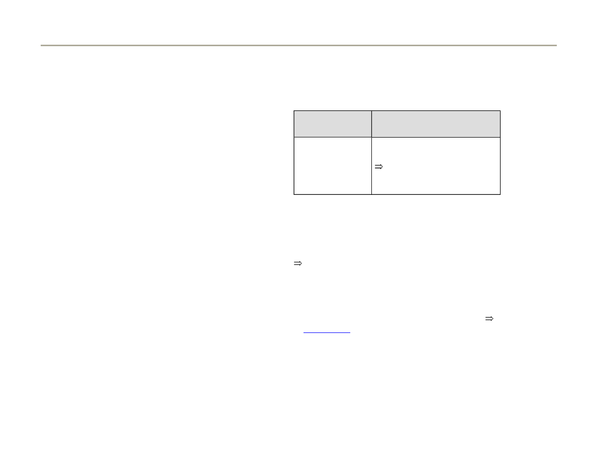
- Disconnect 4-pin connector for each ignition
coil.
Electrical Wiring Diagrams, Troubleshooting & Component Locations
If Ground wiring is OK:
- Check wiring connection from socket 2 of 4-pin connector after body
Ground for open circuit or short circuit to Ground.
- Repair open or short circuit as necessary.
- Check activation of power output stages
Page 28-21
.
Page 24 of 82
Ignition system, checking
1/17/2006
http://127.0.0.1:8080/audi/servlet/Display?action=Goto&type=repair&id=AUDI.C5.FU03.28.1.66.14
28-21
Checking activation of power output stages
- Disconnect harness connectors from all six fuel
injectors.
Note:
It is important to ensure that no fuel is injected
during the test as this would damage the catalytic
converter. The harness connectors on the fuel
injectors must therefore be disconnected.
- Disconnect 4-pin for each ignition coil.
If the specified value is not attained:
- Connect LED voltage tester V.A.G 1527 to following contacts on
connectors for igntion coils.
- Operate starter for a few seconds.
4-pin connector on wiring
harness, terminal
Specification
3 + 2
LED voltage tester must flash
(brief flash)
- Switch ignition off.
Page 25 of 82
Ignition system, checking
1/17/2006
http://127.0.0.1:8080/audi/servlet/Display?action=Goto&type=repair&id=AUDI.C5.FU03.28.1.66.14
28-22
- Connect test box V.A.G 1598/31 to wiring
harness for engine control module. Do not
connect to engine control module itself,
Page
24-20
.
- Check wiring connection from 4-pin connector on ignition coil and
power output stages....
- .....to engine control module for open circuits and shorts circuits to B+
and Ground
4-pin connector VAG1598/31 test box, socket
Cyl. 1
102
Cyl. 2
110
Cyl. 3
94
Cyl. 4
103
Cyl. 5
111
Cyl. 6
95
Wire resistance: max. 1.5 Ohm
Page 26 of 82
Ignition system, checking
1/17/2006
http://127.0.0.1:8080/audi/servlet/Display?action=Goto&type=repair&id=AUDI.C5.FU03.28.1.66.14

28-23
- Repair any open ciruits and short circuits.
Electrical Wiring Diagrams, Troubleshooting &
Component Locations
If there is no fault in the wiring:
- Replace ignition coil with power output stage.
Page 27 of 82
Ignition system, checking
1/17/2006
http://127.0.0.1:8080/audi/servlet/Display?action=Goto&type=repair&id=AUDI.C5.FU03.28.1.66.14

28-24
Motronic ECM power supply relay -J271-
, checking
Location of relay:
Electrical Wiring Diagrams, Troubleshooting &
Component Locations
Note:
The Motronic ECM power supply relay -J271-
supplies the ignition coils with power output
stages and also supplies the ECM on pin 3 and
some other components with voltage. When the
ignition is on, there must be 1 - 12 Volts on
contact at the respective ignition coil.
Check activation wiring from power supply
relay to ECM
- Switch ignition on.
- Remove Motronic ECM power supply relay -
J271- from 3-position relay panel.
- Connect V.A.G 1598/31 test box to wiring
harness for engine control module. Do not
connect to engine control module itself,
Page
24-20
.
Page 28 of 82
Ignition system, checking
1/17/2006
http://127.0.0.1:8080/audi/servlet/Display?action=Goto&type=repair&id=AUDI.C5.FU03.28.1.66.14
28-25
- Check following wiring connections for open
circuit or short circuit:
VAG1598/31 test
box, socket
Power supply relay
terminal
23
4
Electrical Wiring Diagrams,
Troubleshooting &
Component Locations
Wire resistance: max. 1.5 Ohm
- Correct any open/short circuits as necessary.
Electrical Wiring Diagrams, Troubleshooting &
Component Locations
If no wiring fault is found:
- Check voltage supply for power supply relay,
Page 28-26
.
Page 29 of 82
Ignition system, checking
1/17/2006
http://127.0.0.1:8080/audi/servlet/Display?action=Goto&type=repair&id=AUDI.C5.FU03.28.1.66.14

28-26
Checking voltage supply to power supply
relay
- Switch ignition off.
- Connect multimeter for voltage measurement
between terminal 1 on relay socket and Ground.
- Connect multimeter for voltage measurement
between terminal 2 on relay socket and Ground.
Specified value: approx. battery voltage
If the specified value is not attained:
- Check voltage supply according to wiring
diagram.
Electrical Wiring Diagrams, Troubleshooting &
Component Locations
If the specified value is attained:
- Check wiring connection between power supply
relay and engine control module,
Page 28-
27
.
Page 30 of 82
Ignition system, checking
1/17/2006
http://127.0.0.1:8080/audi/servlet/Display?action=Goto&type=repair&id=AUDI.C5.FU03.28.1.66.14
28-27
Checking wiring connection between power
supply relay and engine control module
- Check fuse.
Electrical Wiring Diagrams, Troubleshooting &
Component Locations
If no fault is found with fuse:
- Check following wiring connections for open
circuit or short circuit:
VAG1598/31 test
box, socket
Power supply relay
terminal
3
8
Electrical Wiring Diagrams,
Troubleshooting &
Component Locations
Wire resistance: max. 1.5 Ohm
- Correct open circuit or short circuit as
necessary.
Electrical Wiring Diagrams, Troubleshooting &
Component Locations
Page 31 of 82
Ignition system, checking
1/17/2006
http://127.0.0.1:8080/audi/servlet/Display?action=Goto&type=repair&id=AUDI.C5.FU03.28.1.66.14

If no fault is found in any of the tests:
- Replace Motronic ECM power supply relay -
J271-.
Page 32 of 82
Ignition system, checking
1/17/2006
http://127.0.0.1:8080/audi/servlet/Display?action=Goto&type=repair&id=AUDI.C5.FU03.28.1.66.14

28-28
Intake Air Temperature (IAT) sensor -
G42-, checking
Location of sensor and connector
Page 24-5
.
- Connect vehicle diagnostic, testing and
information system VAS 5051 or VAG1551 scan
tool and select engine electronics control
module by entering address word "01"
Page
01-8
. Ignition must be switched on.
Rapid data transfer
HELP
Select Function XX
Indicated on display
- Press buttons -0- and -8- to select function "Read Measuring Value
Block" and confirm entry with -Q- button.
Read Measuring Value Block
HELP
Input Display Group Number XXX
Indicated on display
- Press buttons -0-, -0- and -4- to select "display group 004" and confirm
entry with -Q- button.
Read Measuring Value Block 4
1
2
3
4
Indicated on display (1...4
display fields)
- Check display value for intake air temperature sensor (display field 4):
Page 33 of 82
Ignition system, checking
1/17/2006
http://127.0.0.1:8080/audi/servlet/Display?action=Goto&type=repair&id=AUDI.C5.FU03.28.1.66.14
28-29
Display fields
1
2
3
4
Display Group 004: Intake air temperature with engine idling
Display
xxxx RPM
xx.xxx V
xxx.x C
xxx.x C
Indicates
Engine speed
Battery voltage
Coolant temperature
Intake air temperature
Work range
min.: 650 RPM
max.: 6800 RPM
min.:10.000 V
max.: 15.000 V
min.: -48.0 C
max.: 143.0 C
min.: -48.0 C
max.: 143.0 C
Specified value
xxxx RPM
12.000...15.000 V
80.0...110.0 C
Between ambient temp. and 120 C
1)
1)
If there is a large difference between the temperature displayed and the ambient temperature at the sensor, check the
sensor and sensor wiring for contact resistance and open circuit.
Page 34 of 82
Ignition system, checking
1/17/2006
http://127.0.0.1:8080/audi/servlet/Display?action=Goto&type=repair&id=AUDI.C5.FU03.28.1.66.14
28-30
Checking wiring:
- Switch ignition off.
- Connect test box VAG1598/31 to wiring harness
for engine control module. Do not connect to
engine control module itself.
Page 24-20
.
- Check for open circuit in wiring between test box and 2 pin harness
connector using wiring diagram.
Specification: max. 1.5
Terminal on 2-pin harness
connector
Contact on control module
connector or test box
1
2
85
108
- Check wiring for short circuits to each other between contacts 1 and 2
on 2-pin connector. Also test for short circuits to B+ or Ground (GND).
Page 35 of 82
Ignition system, checking
1/17/2006
http://127.0.0.1:8080/audi/servlet/Display?action=Goto&type=repair&id=AUDI.C5.FU03.28.1.66.14
28-31
If no malfunction in wire is detected:
Checking sensor
If value does not match the specification:
Note:
In order to install the new sensor, the intake manifold must first be
removed
Page 24-15
.
- Measure resistance between contacts 1 (signal) and 2 (Ground) on
connector for Intake Air Temperature (IAT) sensor -G42-.
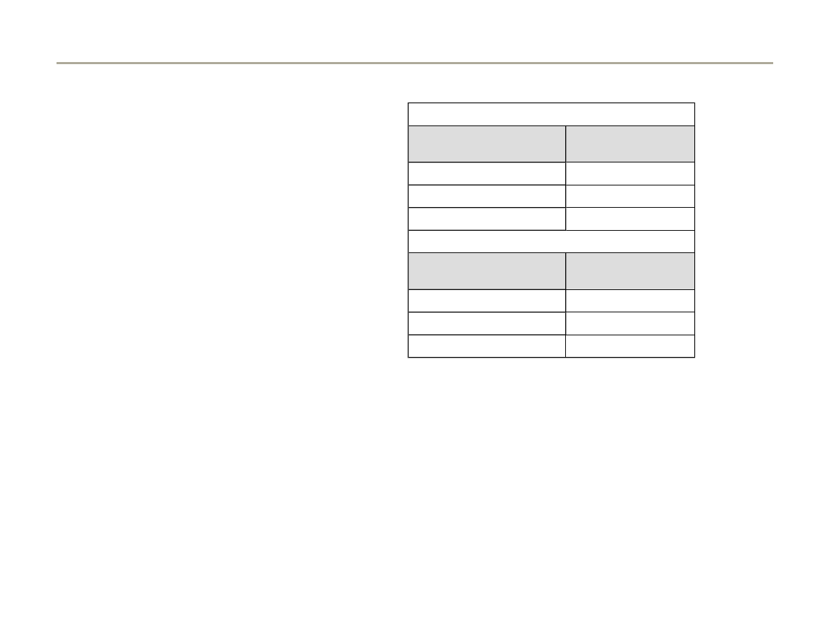
Temperature C Resistance k
-20
approx. 13.8
0
approx. 5.5
20
approx. 2.4
40
approx. 1.1
60
approx. 0.6
- Replace intake air temperature sensor.
Page 36 of 82
Ignition system, checking
1/17/2006
http://127.0.0.1:8080/audi/servlet/Display?action=Goto&type=repair&id=AUDI.C5.FU03.28.1.66.14

28-32
Engine speed (RPM) sensor -G28-,
checking
Note:
The engine speed sender is a combined speed
sensor and reference mark sensor. Without a
signal from the Engine Speed (RPM) sensor -
G28- the engine cannot be started. If the signal
from the Engine Speed (RPM) sensor -G28- fails
while the engine is running, the engine will cut
out immediately.
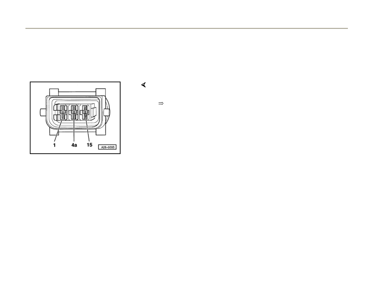
Checking Engine Speed (RPM) sensor
Component location of sensor and connector
Page 24-5
.
- Before performing test, make sure that sensor is
correctly installed and firmly seated.
- Disconnect harness connector for Engine Speed
(RPM) sensor (gray connector).
Page 37 of 82
Ignition system, checking
1/17/2006
http://127.0.0.1:8080/audi/servlet/Display?action=Goto&type=repair&id=AUDI.C5.FU03.28.1.66.14
28-33
Note:
If the specification is not attained:
If the specification is attained:
If the specification is not attained:
If the specification is attained:
- Connect multimeter (Fluke 83 or equivalent) (resistance test range) to
terminals 2 and 3 on connector for engine speed sensor using test lead
from VAG1594 connector test kit.
Specification: approx. 730 - 1000 Ohm
The resistance value for the engine speed sensor is based on a
temperature of 20 C.
The resistance increases as the temperature rises.
- Replace Engine Speed (RPM) sensor.
- Connect multimeter (Fluke 83 or equivalent) (resistance test range)
between terminals 2 and 1 (Ground) and between terminals 3 and 1
(Ground).
Specification: R (infinite Ohms / open circuit) in each test
- Replace Engine Speed (RPM) sensor.
-
Check wiring between sensor connector and engine control module as
Page 38 of 82
Ignition system, checking
1/17/2006
http://127.0.0.1:8080/audi/servlet/Display?action=Goto&type=repair&id=AUDI.C5.FU03.28.1.66.14

follows:
Page 39 of 82
Ignition system, checking
1/17/2006
http://127.0.0.1:8080/audi/servlet/Display?action=Goto&type=repair&id=AUDI.C5.FU03.28.1.66.14
28-34
- Connect VAG1598/31 test box to wiring harness
for engine control module. Do not connect to
engine control module itself
Page 24-20
.
- Test continuity of screening (shielded wire) between contact 1 on
engine speed sensor connector and socket 108 on test box.
Specification: max. 1 .
- Test continuity of negative wire from contact 2 on sensor connector to
socket 90 on test box.
Specification: max. 1 .
- Test continuity of signal wire from contact 3 on sensor connector to
socket 82 on test box.
Specification: max. 1 .
Page 40 of 82
Ignition system, checking
1/17/2006
http://127.0.0.1:8080/audi/servlet/Display?action=Goto&type=repair&id=AUDI.C5.FU03.28.1.66.14
28-35
If the values are not as specified:
- Correct short or open circuit in wiring between
sensor connector and control module connector.
Terminal on sensor
connector
Terminal on control
module connector
1
2
3
108
90
82
- If no open circuits or short circuits are identified,
replace Engine Control Module (ECM)
Page
24-24
.
Page 41 of 82
Ignition system, checking
1/17/2006
http://127.0.0.1:8080/audi/servlet/Display?action=Goto&type=repair&id=AUDI.C5.FU03.28.1.66.14

28-36
Engine Coolant Temperature (ECT)
sensor -G62-, checking
Note:
Component location of coolant temperature
sensor
Page 24-5
.
Test conditions
Engine cold
- Connect vehicle diagnostic, testing and
information system VAS 5051 or VAG1551 scan
tool to vehicle and select engine electronics
control module by entering address word "01"
Page 01-8
. Engine must be at idle.
Page 42 of 82
Ignition system, checking
1/17/2006
http://127.0.0.1:8080/audi/servlet/Display?action=Goto&type=repair&id=AUDI.C5.FU03.28.1.66.14
28-37
Rapid data transfer
HELP
Select function XX
Indicated on display
- Press buttons -0- and -8- to select function "Read Measuring Value
Block" and confirm entry with -Q- button.
Read Measuring Value Block
Input display group number XXX
Indicated on display
- Press buttons -0-, -0- and -4- to select "display group 004" and confirm
entry with -Q- button.
Read Measuring Value Block 4
1
2
3
4
Indicated on display
- Check specification in display field 3.
Page 43 of 82
Ignition system, checking
1/17/2006
http://127.0.0.1:8080/audi/servlet/Display?action=Goto&type=repair&id=AUDI.C5.FU03.28.1.66.14
28-38
Display fields
1
2
3
4
Display Group 004: Coolant temperature with engine idle
Display
xxxx RPM
xx.xxx V
xxx.x C
xxx.x C
Indicates
Engine speed RPM Battery voltage
Coolant temperature
Intake air temperature
Specified value
XXXX RPM
12.0...15.0 V Temperature must increase evenly Ambient temperature
up to 120 C
Page 44 of 82
Ignition system, checking
1/17/2006
http://127.0.0.1:8080/audi/servlet/Display?action=Goto&type=repair&id=AUDI.C5.FU03.28.1.66.14
28-39
If display field 3 does not display a realistic
value:
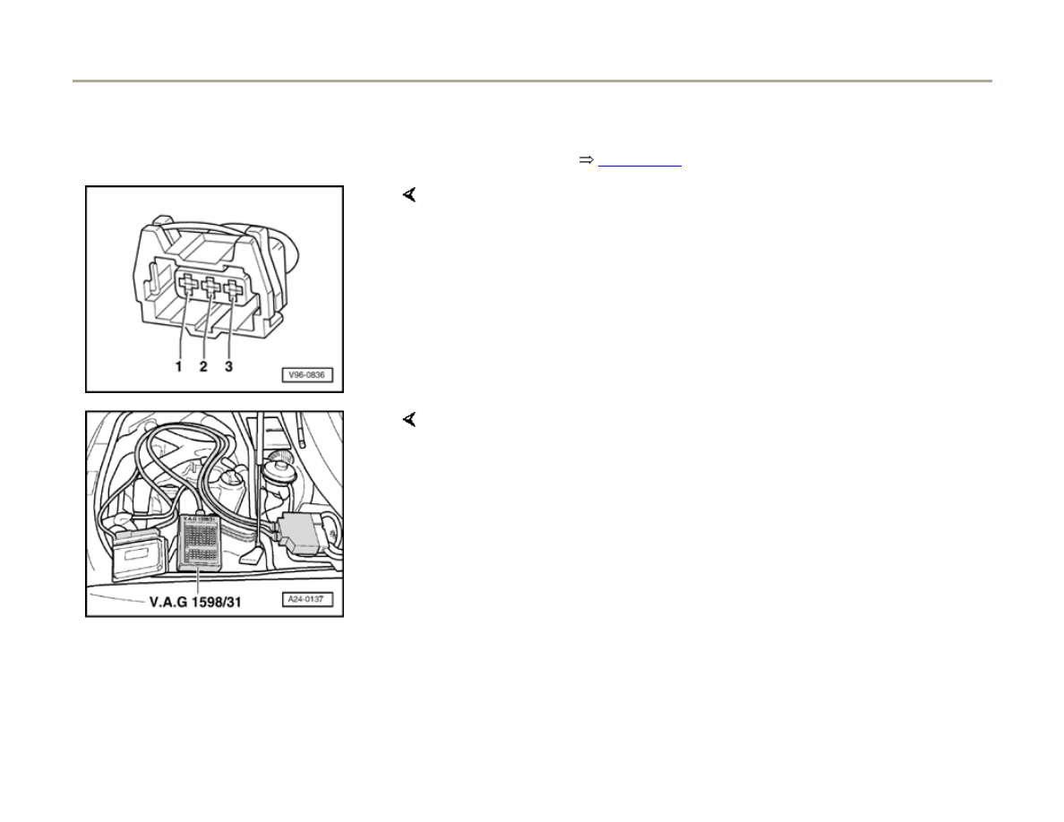
- Disconnect harness connector from coolant
temperature sensor.
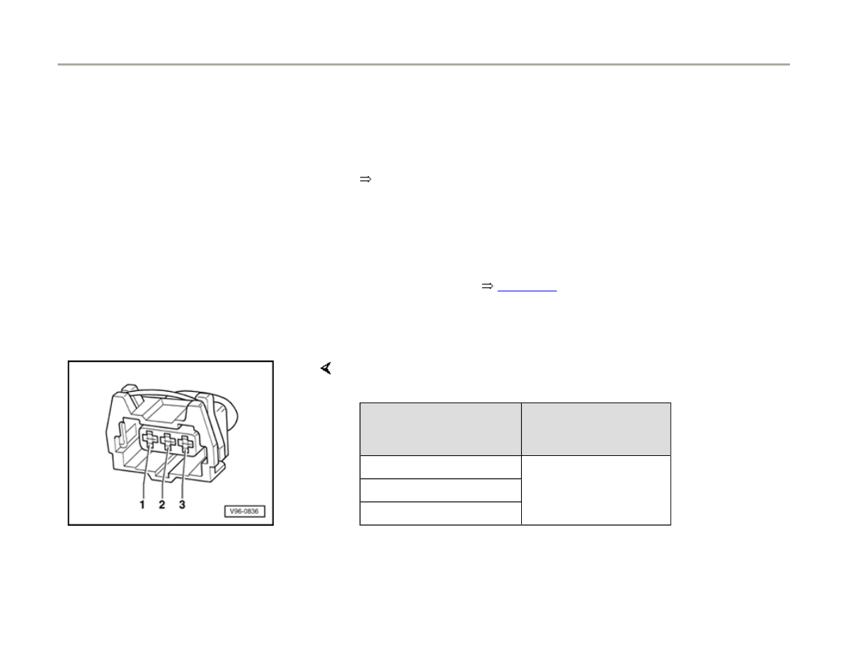
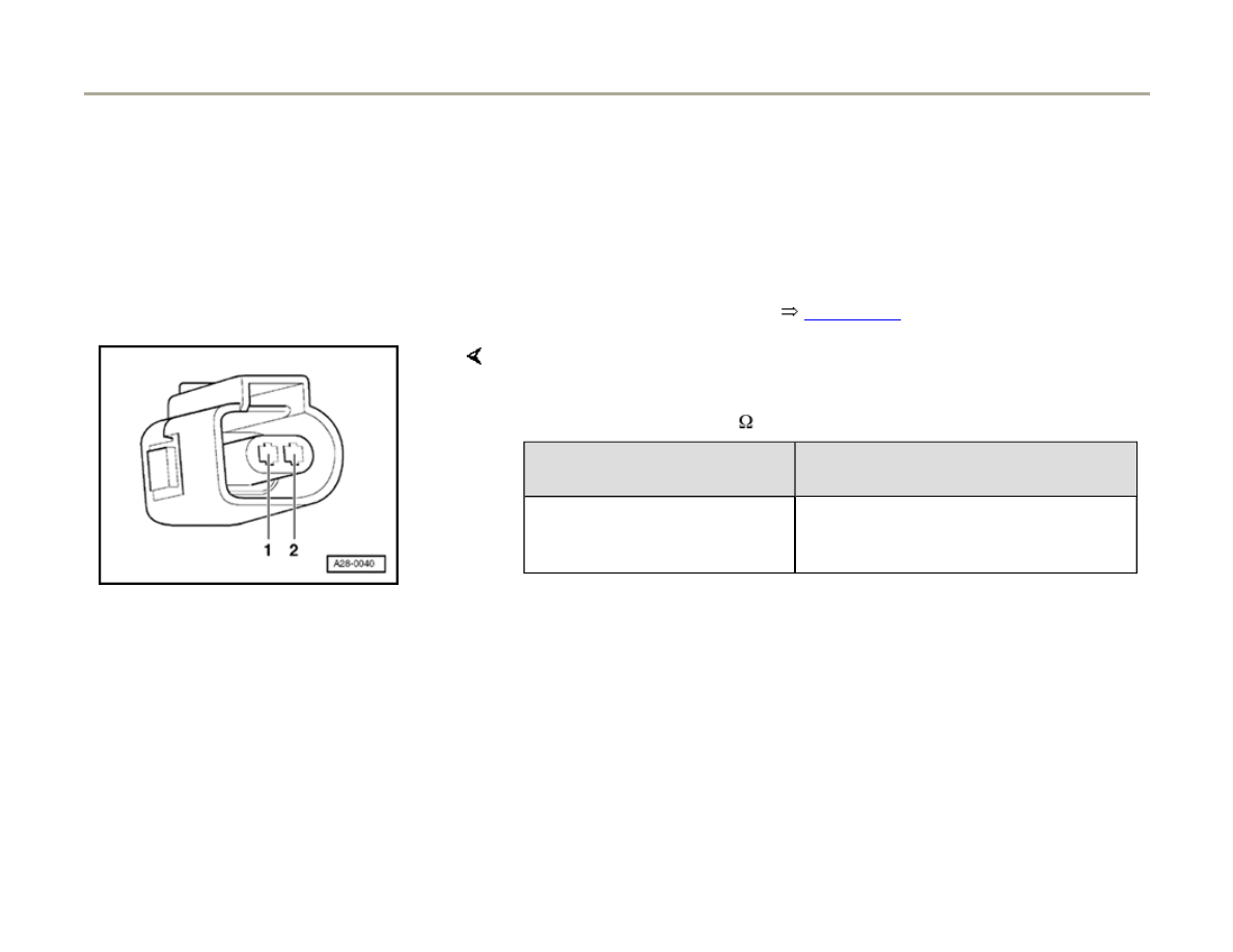
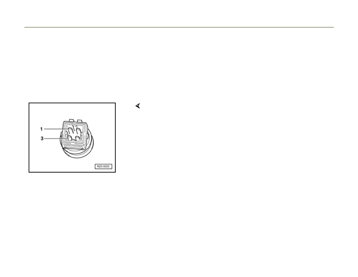
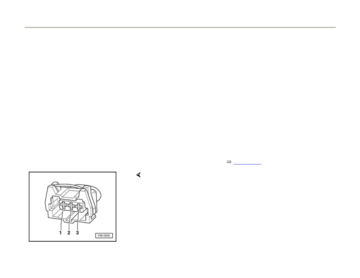
Coolant temperature sensor with square
connector
- Connect multi-meter (resistance measurement) between terminals 1
and 3 of sensor.
Page 45 of 82
Ignition system, checking
1/17/2006
http://127.0.0.1:8080/audi/servlet/Display?action=Goto&type=repair&id=AUDI.C5.FU03.28.1.66.14
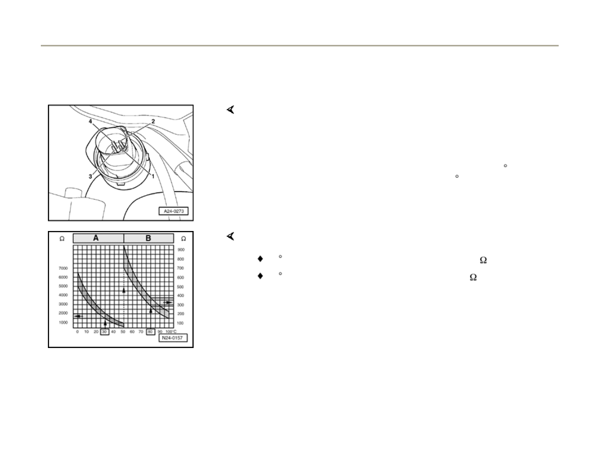
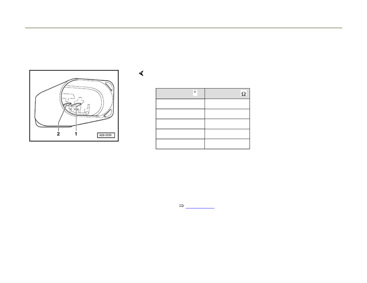
28-40
Coolant temperature sensor with oval
connector
All
Scale A shows resistance values for temperature range 0 - 50 C and
scale B the values for temperature range 50 - 100 C.
- Connect multi-meter (resistance measurement) between terminals 3
and 4 of sensor.
Examples:
If value does not match the specification:
30 C corresponds to a resistance from 1500...2000
80 C corresponds to a resistance from 275...375
- Replace coolant temperature sensor.
Page 46 of 82
Ignition system, checking
1/17/2006
http://127.0.0.1:8080/audi/servlet/Display?action=Goto&type=repair&id=AUDI.C5.FU03.28.1.66.14
28-41
If the value does match the specification:
- Connect test box VAG1598/31 to wiring harness
for engine control module. Do not connect to
engine control module itself.
Page 24-20
.
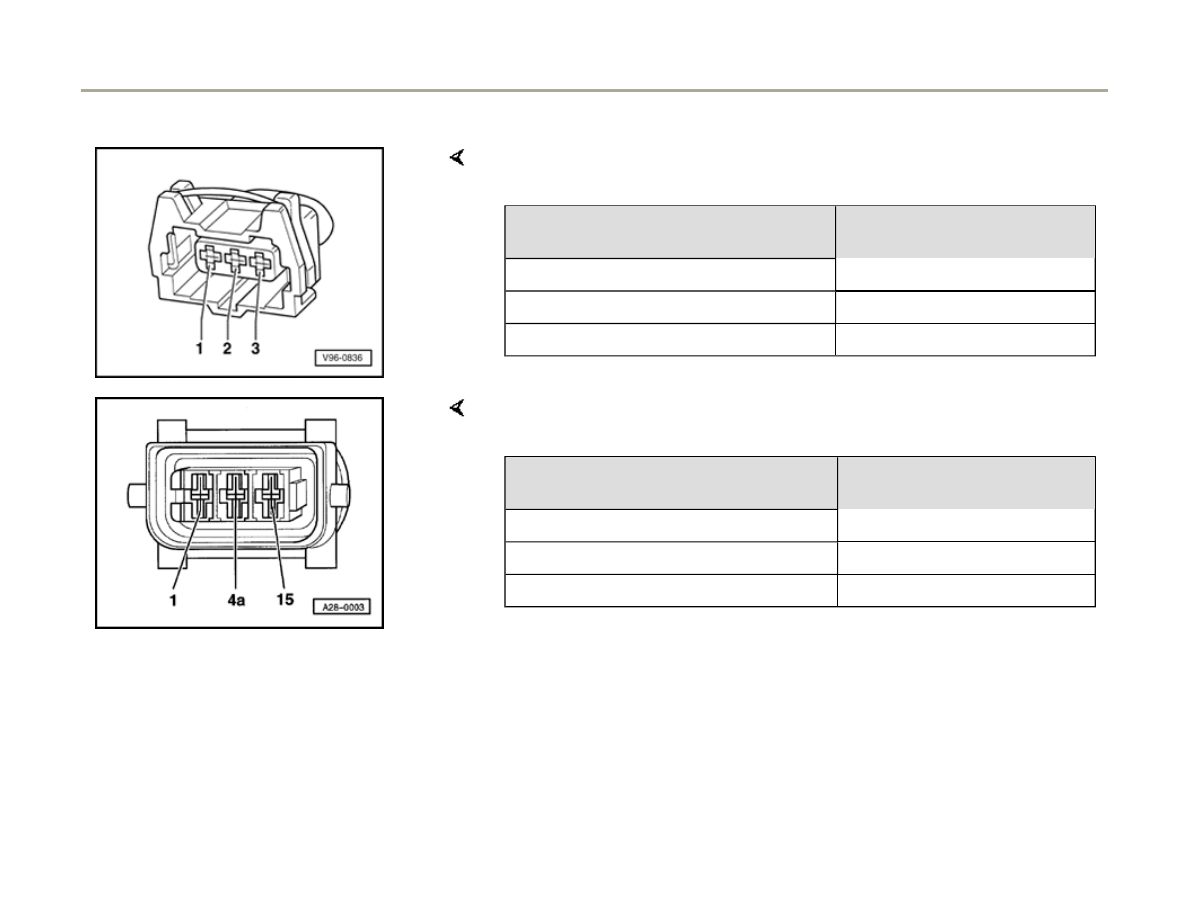
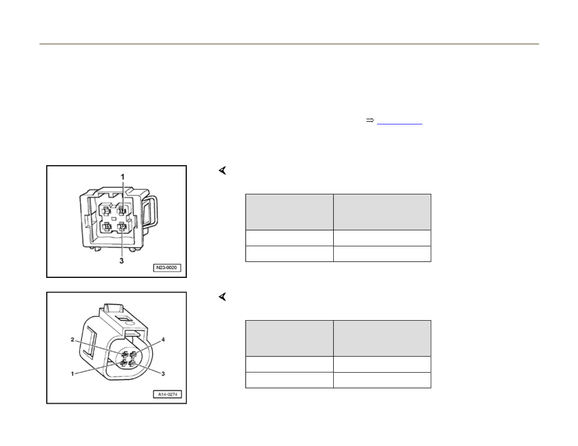
Coolant temperature sensor with square
connector
Coolant temperature sensor with oval connector
- Check following wiring connections for open circuits and short circuits
to B+ or Ground (GND)
Harness connector
Terminal
VAG1598/31 test box
Socket
1 (Signal)
93
3
108
- Check following wiring connections for open circuits and short circuits
to B+ or Ground (GND)
Harness connector
Terminal
VAG1598/31 test box
Socket
3
108
4 (Signal)
93
Page 47 of 82
Ignition system, checking
1/17/2006
http://127.0.0.1:8080/audi/servlet/Display?action=Goto&type=repair&id=AUDI.C5.FU03.28.1.66.14

28-42
All
- Check wires for short circuits to each other.
- If necessary eliminate open circuit or short
circuit.
If no malfunction is identified in the wiring:
- Replace Engine Control Module (ECM)
Page
24-24
.
Page 48 of 82
Ignition system, checking
1/17/2006
http://127.0.0.1:8080/audi/servlet/Display?action=Goto&type=repair&id=AUDI.C5.FU03.28.1.66.14

28-43
Control module voltage supply,
checking
Procedure is valid for engines with Engine
code. Procedure for Engine code BEL
Page
28-45
Test requirements
Fuse for Engine Control Module (ECM) OK
Electrical Wiring Diagrams, Troubleshooting &
Component Locations.
Battery voltage at least 11 V
Generator OK
- Connect test box VAG1598/31 to wiring harness
for engine control module. Do not connect to
engine control module itself.
Page 24-20
.
- Switch ignition on.
Note:
The B+ voltage supply for the engine control
module comes via terminal 3 (terminal 15) and
terminal 62 (terminal 30).
Page 49 of 82
Ignition system, checking
1/17/2006
http://127.0.0.1:8080/audi/servlet/Display?action=Goto&type=repair&id=AUDI.C5.FU03.28.1.66.14

The Ground (GND) connection for the engine
control module is via terminals 1 and 2.
Page 50 of 82
Ignition system, checking
1/17/2006
http://127.0.0.1:8080/audi/servlet/Display?action=Goto&type=repair&id=AUDI.C5.FU03.28.1.66.14
28-44
- Connect multimeter VAG1526 (voltage
measurement range) to following contacts on
test box:
Contact
Specification
3 + 2
approx. battery voltage
3 + 1
approx. battery voltage
62 + 2 approx. battery voltage
If the specifications are not obtained:
- Check wiring.
Electrical Wiring Diagrams, Troubleshooting &
Component Locations.
Page 51 of 82
Ignition system, checking
1/17/2006
http://127.0.0.1:8080/audi/servlet/Display?action=Goto&type=repair&id=AUDI.C5.FU03.28.1.66.14

28-45
Control module voltage supply, checking,
Engine code BEL
Test requirements
Engine control module fuse OK
Electrical Wiring Diagrams, Troubleshooting &
Component Locations
Battery voltage 11 V minimum
Generator OK
- Connect V.A.G 1598/31 test box to wiring
harness for engine control module. Do not
connect to engine control module itself,
Page
24-20
.
- Switch ignition on.
Note:
The B+ voltage supply for the engine control
module travels via connector terminal 3 (from
Motronic ECM power supply relay -J271-),
connector terminal 21 (terminal 15) and
connector terminal 62 (terminal 30).
Page 52 of 82
Ignition system, checking
1/17/2006
http://127.0.0.1:8080/audi/servlet/Display?action=Goto&type=repair&id=AUDI.C5.FU03.28.1.66.14

Ground (GND) supply of the engine control
module is via connector terminals 1 and 2.
Page 53 of 82
Ignition system, checking
1/17/2006
http://127.0.0.1:8080/audi/servlet/Display?action=Goto&type=repair&id=AUDI.C5.FU03.28.1.66.14
28-46
- Connect multimeter for voltage measurement to
following contacts on test box:
Contact
Specification
3 + 2
approx. battery voltage
3 + 1
approx. battery voltage
21 + 1 approx. battery voltage
62 + 2 approx. battery voltage
If the specifications are not obtained:
- Check wiring connections.
Electrical Wiring Diagrams, Troubleshooting &
Component Locations
If the specifications on terminal 3 are not
obtained:
- Check Motronic ECM power supply relay,
Page 28-24
.
Page 54 of 82
Ignition system, checking
1/17/2006
http://127.0.0.1:8080/audi/servlet/Display?action=Goto&type=repair&id=AUDI.C5.FU03.28.1.66.14
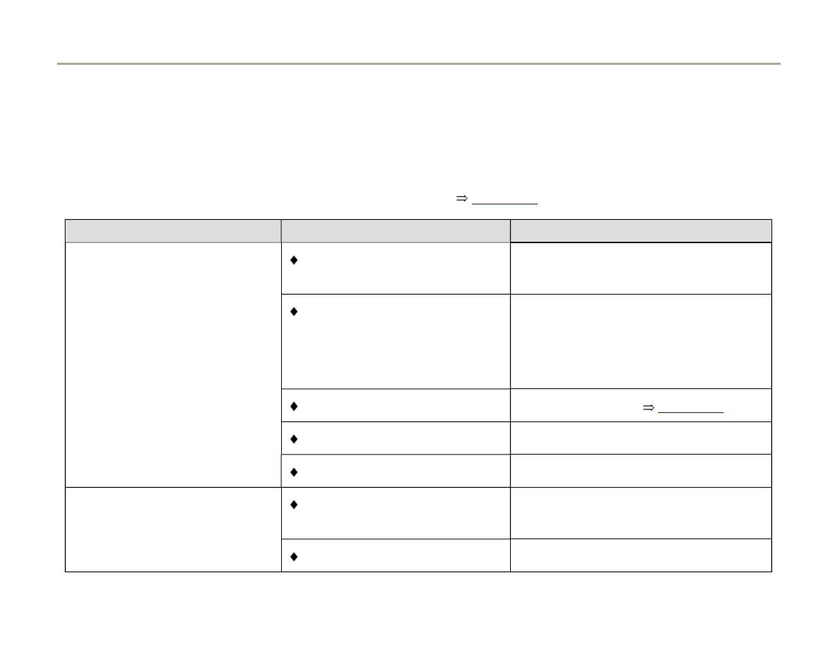
28-47
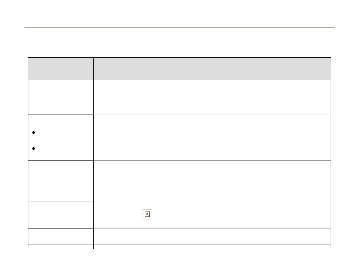
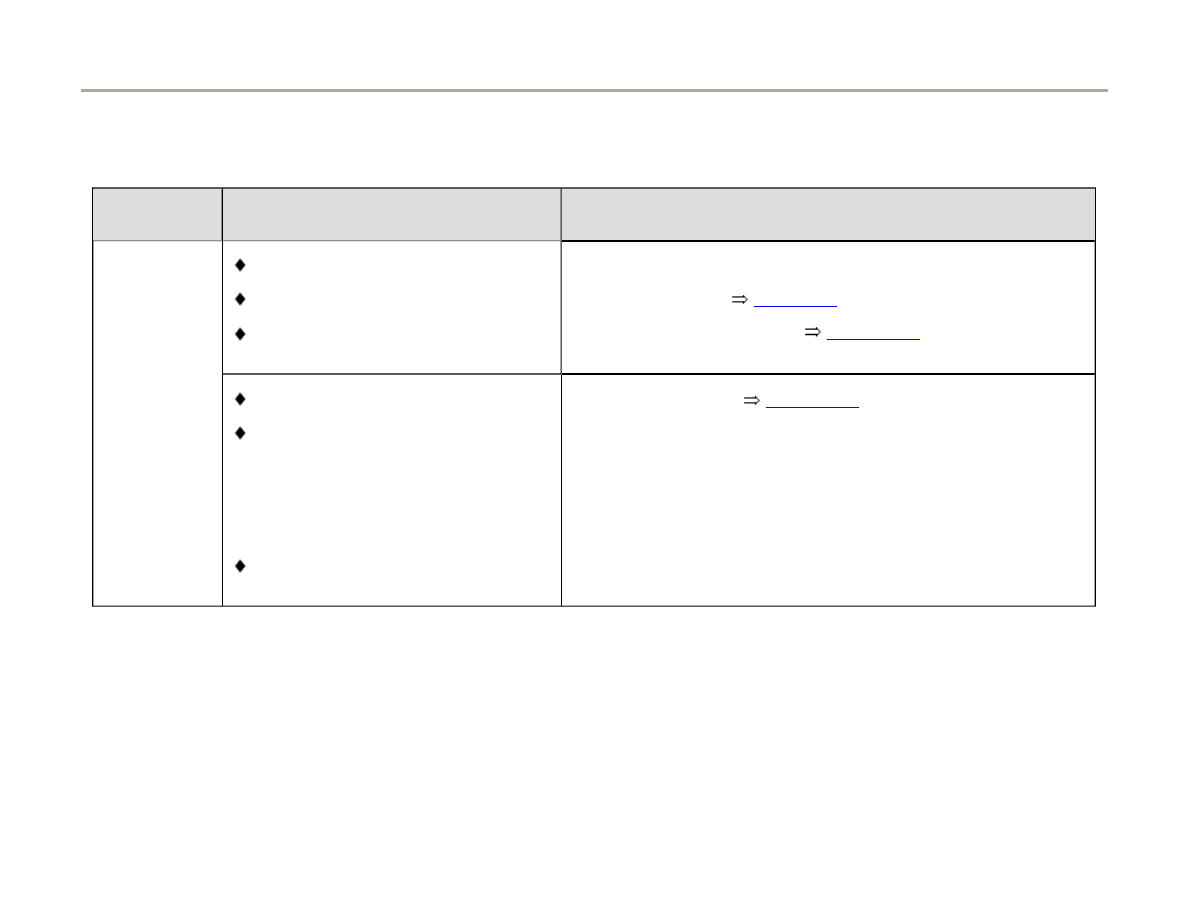
Knock sensor control limit, checking
If the malfunction message "Knock control
regulation reached" is recorded in the DTC
memory the following tests must be carried out.
See also measuring value blocks 20, 21, 22, 23
and 24
Page 28-48
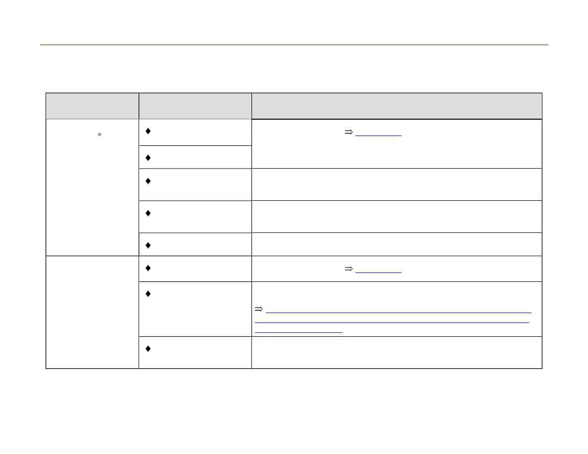
Possible cause of malfunction
Corrective action
Malfunction
message relating to all cylinders
Poor fuel quality
- Change to higher quality fuel (see Owner's
Manual)
or
malfunction
message relating to all cylinders in
one bank
Incorrect tightening torque on
knock sensor
- Loosen knock sensor, then tighten to 20
Nm (15 ft lb)
Knock sensor faulty
- Check knock sensor
Page 28-54
.
Corrosion on connector
Loose components on engine
- Secure loose components
Malfunction
message relating to one cylinder
Mechanical engine damage
- Check compression pressure
Loose components on engine
- Secure loose components
Page 55 of 82
Ignition system, checking
1/17/2006
http://127.0.0.1:8080/audi/servlet/Display?action=Goto&type=repair&id=AUDI.C5.FU03.28.1.66.14
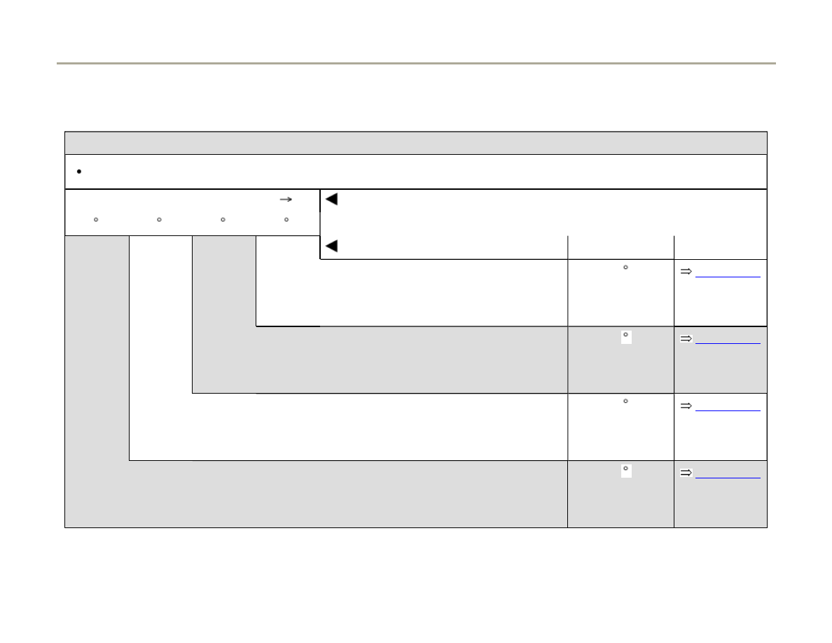
28-48
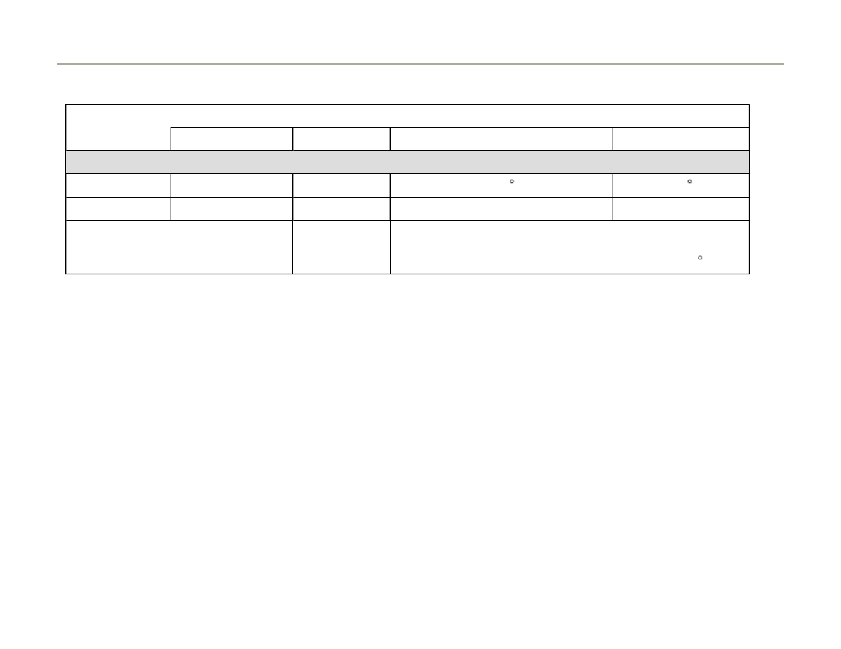
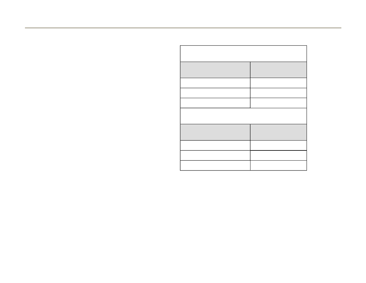
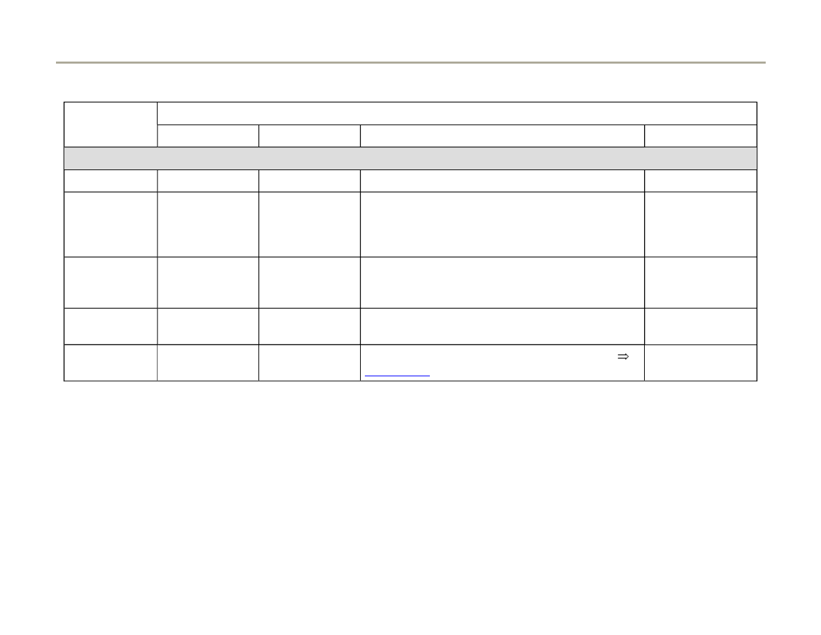
Measuring value blocks for ignition timing angle retard
Display Group 020 -Ignition- Knock control
Driving mode
Read measuring value block 20
Indicated on display
xx.x KW xx.x KW xx.x KW xx.x KW
1
2
3
4
Display fields
Specified value
Evaluation
Ignition timing retard via knock control:
cylinder 4
0...12 KW
(crankshaft
angle)
Page 28-53
Ignition timing retard via knock control:
cylinder 3
0...12 KW
(crankshaft
angle)
Page 28-53
Ignition timing retard via knock control: cylinder 2
0...12 KW
(crankshaft
angle)
Page 28-53
Ignition timing retard via knock control: cylinder 1
0...12 KW
(crankshaft
angle)
Page 28-53
Note:
Page 56 of 82
Ignition system, checking
1/17/2006
http://127.0.0.1:8080/audi/servlet/Display?action=Goto&type=repair&id=AUDI.C5.FU03.28.1.66.14

The displayed digit values in display fields 1 to 4 reflects the actual "ignition timing retard" via knock control from the individual
cylinders. The ignition timing retard occurs via KW (crankshaft angle).
Page 57 of 82
Ignition system, checking
1/17/2006
http://127.0.0.1:8080/audi/servlet/Display?action=Goto&type=repair&id=AUDI.C5.FU03.28.1.66.14
28-49
Display Group 021 -Ignition- Knock control
Driving mode
Read measuring value block 21
Indicated on display
xx.x KW
xx.x KW
1
2
3
4
Display fields
Specified value
Evaluation
Ignition timing retard via knock control: cylinder 6
0...12 KW
(crankshaft angle)
Page 28-53
Ignition timing retard via knock control: cylinder 5
0...12 KW
(crankshaft angle)
Page 28-53
Note:
The displayed digit values in display fields 1 and 2 reflects the actual "ignition timing retard" via knock control from the
individual cylinders. The ignition timing retard occurs via KW (crankshaft angle).
Page 58 of 82
Ignition system, checking
1/17/2006
http://127.0.0.1:8080/audi/servlet/Display?action=Goto&type=repair&id=AUDI.C5.FU03.28.1.66.14

28-50
Display Group 022 -Ignition- Knock control
Driving mode
Read measuring value block
22
Indicated on display
xx.x RPM x.x % xx.x KW xx.x KW
1
2
3
4
Display fields
Specified value
Evaluation
Ignition timing retard via knock control:
cylinder 2
0...12 KW
(crankshaft
angle)
Page 28-53
Ignition timing retard via knock control:
cylinder 1
0...12 KW
(crankshaft
angle)
Page 28-53
Engine load
15 - 175 %
Engine speed RPM
650 - 6800 RPM
Note:
The displayed digit values in display fields 3 and 4 reflects the actual "ignition timing retard" via knock control from cylinders 1
and 2. The ignition timing retard occurs via KW (crankshaft angle).
Page 59 of 82
Ignition system, checking
1/17/2006
http://127.0.0.1:8080/audi/servlet/Display?action=Goto&type=repair&id=AUDI.C5.FU03.28.1.66.14

28-51
Display Group 023 -Ignition- Knock control
Driving mode
Read measuring value block
23
Indicated on display
xx.x RPM x.x % xx.x KW xx.x KW
1
2
3
4
Display fields
Specified value
Evaluation
Ignition timing retard via knock control:
cylinder 4
0...12 KW
(crankshaft
angle)
Page 28-53
Ignition timing retard via knock control:
cylinder 3
0...12 KW
(crankshaft
angle)
Page 28-53
Engine load
15 - 175 %
Engine speed RPM
650 - 6800 RPM
Note:
The displayed digit values in display fields 3 and 4 reflects the actual "ignition timing retard" via knock control from cylinders 3
and 4. The ignition timing retard occurs via KW (crankshaft angle).
Page 60 of 82
Ignition system, checking
1/17/2006
http://127.0.0.1:8080/audi/servlet/Display?action=Goto&type=repair&id=AUDI.C5.FU03.28.1.66.14
28-52
Display Group 024 -Ignition- Knock control
Driving mode
Read measuring value block
24
Indicated on display
xx.x RPM x.x % xx.x KW xx.x KW
1
2
3
4
Display fields
Specified value
Evaluation
Ignition timing retard via knock control:
cylinder 6
0...12 KW
(crankshaft
angle)
Page 28-53
Ignition timing retard via knock control:
cylinder 5
0...12 KW
(crankshaft
angle)
Page 28-53
Engine load
15 - 175 %
Engine speed RPM
650 - 6800 RPM
Note:
The displayed digit values in display fields 3 and 4 reflects the actual "ignition timing retard" via knock control from cylinders 5
and 6. The ignition timing retard occurs via KW (crankshaft angle).
Page 61 of 82
Ignition system, checking
1/17/2006
http://127.0.0.1:8080/audi/servlet/Display?action=Goto&type=repair&id=AUDI.C5.FU03.28.1.66.14
28-53
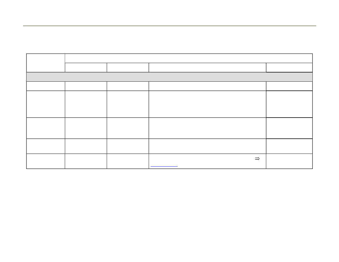
Evaluation display groups 20/21/22/23/24, - Ignition timing angle retard
Indicated on
display
Malfunction cause
Corrective action
All cylinders greater
than 12 KW
Knock sensor faulty
- Check knock sensor
Page 28-54
.
Corroded connection
Knock sensor incorrect
tightening torque
- Loosen and tighten knock sensor with 20 Nm (15 ft lb)
Components on engine
loose
- Tighten components
Low fuel grade
- Change fuel grade
One cylinder deviates
clearly from others
Corroded connection
- Check knock sensor
Page 28-54
.
Engine damage
Repair Manual, 2.7 Liter V6 5V BiTurbo,Engine Mechanical, Engine
Code(s): APB, BEL, Repair Group 15; Cylinder head removing, check
compression pressure
- Check compression pressure:
Components on engine
loose
- Tighten components
Page 62 of 82
Ignition system, checking
1/17/2006
http://127.0.0.1:8080/audi/servlet/Display?action=Goto&type=repair&id=AUDI.C5.FU03.28.1.66.14
28-54
Knock Sensor (KS) 1 -G61- and Knock
Sensor (KS) 2 -G66-, checking
Notes:
It is not possible to perform an electrical test of
the knock sensors themselves.
Use only gold-plated terminals when repairing
the terminals in the plug connectors for the
knock sensors.
To ensure that the knock sensors function
properly it is important to keep exactly to the
specified tightening torque of 20 Nm (15 ft lb)
Check for corrosion in connection between
knock sensor and wiring harness.
Checking knock sensors
Note:
- Disconnect harness connector for relevant knock sensor in engine
compartment.
Component location overview
Page 24-5
.
In order to reach the connector for the knock sensor for cylinder bank
2, first remove the bolts securing the coolant reservoir and move the
Page 63 of 82
Ignition system, checking
1/17/2006
http://127.0.0.1:8080/audi/servlet/Display?action=Goto&type=repair&id=AUDI.C5.FU03.28.1.66.14

coolant reservoir to one side. Coolant hoses remain attached.
Page 64 of 82
Ignition system, checking
1/17/2006
http://127.0.0.1:8080/audi/servlet/Display?action=Goto&type=repair&id=AUDI.C5.FU03.28.1.66.14
28-55
Assignment of connectors for engines with
engine code BEL
Page 28-56
.
If there is a connection between the terminals.
Note:
If there is no short circuit
Checking wiring between knock sensors and engine control module
- Check for short circuits between all three terminals in knock sensor
connector (terminals 1 + 2, 1 + 3 and 2 + 3).
Specification: There must be no contact between the wires (infinite ).
- Replace knock sensor.
In order to reach the knock sensors, first remove the air duct
Page
24-52
.
Use special tool 3247 to remove the knock sensors.
- Check wiring for knock sensors.
- Connect VAG1598/31 test box to wiring harness for engine control
module. Do not connect to engine control module itself
Page 24-20
.
Page 65 of 82
Ignition system, checking
1/17/2006
http://127.0.0.1:8080/audi/servlet/Display?action=Goto&type=repair&id=AUDI.C5.FU03.28.1.66.14
28-56
Connectors for Engine code BEL
Assignment of connector wiring in vehicles with engine code BEL
Assignment of 4-pin connectors on knock sensors in vehicles with engine
code BEL
Page 66 of 82
Ignition system, checking
1/17/2006
http://127.0.0.1:8080/audi/servlet/Display?action=Goto&type=repair&id=AUDI.C5.FU03.28.1.66.14
28-57
Assignment of connectors for engines with
engine code BEL
Page 28-56
- Check wiring connection from relevant sensor connector to...
- ....Engine Control Module (ECM) for open circuit and/or short to B+ or
Ground (GND).
Page 67 of 82
Ignition system, checking
1/17/2006
http://127.0.0.1:8080/audi/servlet/Display?action=Goto&type=repair&id=AUDI.C5.FU03.28.1.66.14
28-58
Knock Sensor (KS) 1 -G61- (Bank 1)
3-pin connector on
wiring harness, socket
VAG1598/31 test
box, socket
1 (Ground)
99
2 (signal)
106
3 (shielded)
108
Knock sensor (KS) 2 -G66- (Bank 2)
3-pin connector on
wiring harness, socket
VAG1598/31 test
box, socket
1 (Ground)
99
2 (signal)
107
3 (shielded)
108
Resistance in wiring: max. 1.5 ohm
- Repair any open/short circuit as necessary.
Page 68 of 82
Ignition system, checking
1/17/2006
http://127.0.0.1:8080/audi/servlet/Display?action=Goto&type=repair&id=AUDI.C5.FU03.28.1.66.14
28-59
Camshaft Position (CMP) sensor 2 -
G163- and Camshaft Position (CMP)
sensor 1 -G40-, checking
Notes:
Component locations of CMP sensors
Page
24-5
.
The Camshaft Position (CMP) sensor 2 -G163-
is located at the rear of the left-hand cylinder
head (Bank 2).
The Camshaft Position (CMP) sensor 1 -G40- is
located at the front of the right-hand cylinder
head (Bank 1).
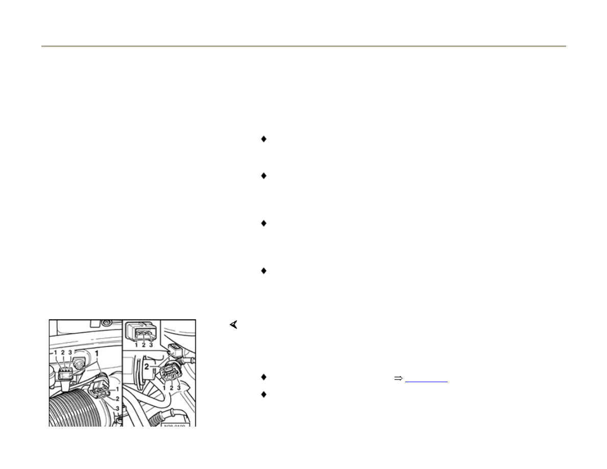
Checking activation of CMP sensor
Use test leads VAG1594 connector test kit when
performing the following tests.
- Push back rubber grommet on relevant CMP
sensor connector.
Note:
- Connect VAG1527 LED voltage tester to terminals 1 and 2 of CMP
sensor connector from behind (without disconnecting connector from
sensor).
Page 69 of 82
Ignition system, checking
1/17/2006
http://127.0.0.1:8080/audi/servlet/Display?action=Goto&type=repair&id=AUDI.C5.FU03.28.1.66.14

The connector terminals are numbered on the back of the connector.
Page 70 of 82
Ignition system, checking
1/17/2006
http://127.0.0.1:8080/audi/servlet/Display?action=Goto&type=repair&id=AUDI.C5.FU03.28.1.66.14

28-60
- Operate starter for few seconds.
LED voltage tester should blink briefly once
every two engine revolutions.
Note:
LED voltage testers with a low current draw
continue to glow faintly between impulses from
the engine control module (rather than going out
completely) and become much brighter when
receiving an impulse.
If the LED voltage tester does not blink:
- Check voltage supply.
Checking voltage supply for CMP sensor
- Disconnect harness connector from relevant
CMP sensor.
- Switch ignition on.
Page 71 of 82
Ignition system, checking
1/17/2006
http://127.0.0.1:8080/audi/servlet/Display?action=Goto&type=repair&id=AUDI.C5.FU03.28.1.66.14
28-61
Checking signal wire for CMP sensor
Checking Ground (GND) wire for CMP sensor
- Connect multimeter (Fluke 83 or equivalent) (voltage measurement
range) between engine Ground (GND) and socket 1 of connector.
Specification: approx. 5 V
- Connect multimeter (Fluke 83 or equivalent) (voltage measurement
range) between engine Ground (GND) and socket 2 of relevant
connector.
Specification: approx. battery voltage
- Connect VAG1598/31 test box to wiring harness for engine control
module. Do not connect to engine control module itself
Page 24-20
.
- Connect multimeter (Fluke 83 or equivalent) (resistance measurement
range) between socket 3 on relevant connector and contact 108 of test
box.
Specification: Continuity
Resistance in wiring: max. 1.5 Ohms
Page 72 of 82
Ignition system, checking
1/17/2006
http://127.0.0.1:8080/audi/servlet/Display?action=Goto&type=repair&id=AUDI.C5.FU03.28.1.66.14
28-62
If all specifications are reached but the LED
voltage tester does not blink (measurement
taken between terminals 1 and 2 without
unplugging connector and while operating
starter):
- Replace relevant CMP sensor.
If specifications are obtained:
- Check wiring.
Checking wiring between CMP sensor and
Engine Control Module (ECM)
- Connect VAG1598/31 test box to wiring harness
for engine control module. Do not connect to
engine control module itself
Page 24-20
.
- Check wiring connection from CMP sensor to engine control module for
open circuit and/or short circuit to B+ or Ground (GND).
Page 73 of 82
Ignition system, checking
1/17/2006
http://127.0.0.1:8080/audi/servlet/Display?action=Goto&type=repair&id=AUDI.C5.FU03.28.1.66.14
28-63
Camshaft Position (CMP) sensor 2 -G163-
(Bank 2)
3-pin connector on
wiring harness, socket
VAG1598/31 test
box, socket
1 (B+)
98
2 (signal)
86
3 (Ground (GND))
108
Camshaft Position (CMP) sensor 1 -G40-
(Bank 1)
3-pin connector on
wiring harness, socket
VAG1598/31 test
box, socket
1 (positive)
98
2 (signal)
87
3 (Ground (GND))
108
Resistance in wiring: max. 1.5 ohm
- Repair any open/short circuit as necessary.
Page 74 of 82
Ignition system, checking
1/17/2006
http://127.0.0.1:8080/audi/servlet/Display?action=Goto&type=repair&id=AUDI.C5.FU03.28.1.66.14

28-64
If all the test results so far have been OK but a
malfunction related to the camshaft position
sensor (Hall sensor) is displayed again after
erasing the DTC memory as a test measure, the
following might be the cause:
- Rotor ring (trigger wheel) for camshaft position
sensor (Hall sensor) misaligned; test phase
position.
Checking phase position of CMP sensor
- Connect vehicle diagnostic, testing and
information system VAS5051 or VAG1551 scan
tool and select engine electronics control
module by entering address word "01"
Page
01-8
. Engine must be idling.
Rapid data transfer
HELP
Select function XX
Indicated on display
- Press buttons -0- and -8- to select function "Read Measuring Value
Block" and confirm entry with -Q- button.
Read Measuring Value Block
Input display group number XXX
Indicated on display
- Press buttons -0-, -9- and -3- to select "display group 093" and confirm
entry with -Q- button.
Page 75 of 82
Ignition system, checking
1/17/2006
http://127.0.0.1:8080/audi/servlet/Display?action=Goto&type=repair&id=AUDI.C5.FU03.28.1.66.14
28-65
Read Measuring Value Block 93
1
2
3
4
Indicated on display
- Check specified display values for CMP sensors.
Display fields
1
2
3
4
Display Group 093: Phase positions of Hall sensors (Bank 1 and Bank 2) with engine idling
Display
xxx RPM
xx %
0 6 KW
0 6 KW
Indicates
Engine
speed
(RPM)
Engine
load
Phase position
Bank 1
Phase position
Bank 2
Work
range
min.: 750
RPM
max.:
6800
RPM
min.: 15
%
max.: 175
%
-20.3 to 14.8 KW
-20.3 to 14.8 KW
Specified
value
650 - 850
RPM
15...25%
0 6 KW
0 6 KW
Note
If readouts do not match specifications, unbolt CMP sensor and check whether
rotor ring is properly mounted on camshaft. If it is incorrectly mounted, the
locating lug will be flattened when the securing bolt is tightened. Also check
valve timing.
Repair Manual, 2.7 Liter V6 5V BiTurbo Engine Mechanical,Engine Code(s): APB,
BEL, Repair Group 13; Crankcase ventilation, Ribbed belt removing and installing,
Timing belt removing and installing
Page 76 of 82
Ignition system, checking
1/17/2006
http://127.0.0.1:8080/audi/servlet/Display?action=Goto&type=repair&id=AUDI.C5.FU03.28.1.66.14

28-66
Misfire recognition, checking
Test sequence
- Connect vehicle diagnostic, testing and
information system VAS5051 or VAG1551 scan
tool and select engine electronics control
module by entering address word "01"
Page
01-8
. Engine must be at idle.
Rapid data transfer
HELP
Select function XX
Indicated on display
- Press buttons -0- and -8- to select function "Read Measuring Value
Block" and confirm entry with -Q- button.
Read Measuring Value Block
Input display group number XXX
Indicated on display
- Press buttons -0-, -1- and -4- to select "display group 014" and confirm
entry with -Q- button.
Read Measuring Value Block 14
1
2
3
4
Indicated on display
- Check misfire recognition.
Page 77 of 82
Ignition system, checking
1/17/2006
http://127.0.0.1:8080/audi/servlet/Display?action=Goto&type=repair&id=AUDI.C5.FU03.28.1.66.14
28-67
Display fields
1
2
3
4
Display Group 014: Misfire recognition
Display
xxx / RPM
xx.x %
xxx
---
Indicated
Engine speed
(RPM)
Load
Total misfires
Misfire
recognition
Work range
min.: 650
RPM
max.: 6800
RPM
min.: 0
max.:
175
activated
locked
Specified
value
650 - 720
RPM
15.0 -
25.0 %
0...15
activated
Note
---
---
If specified value is not reached: Evaluation display field
3
Page 28-68
see also
Page 28-69
---
If specified value is reached:
- Press button.
Rapid Data Transfer
HELP
Select function XX
Indicated on display (select function)
Page 78 of 82
Ignition system, checking
1/17/2006
http://127.0.0.1:8080/audi/servlet/Display?action=Goto&type=repair&id=AUDI.C5.FU03.28.1.66.14
28-68
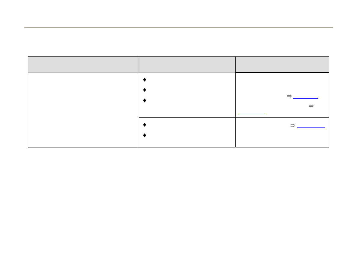
Evaluation display group 014, display field 3
Display field:
3
Possible cause
Corrective action
greater than
15
Spark plug faulty
Spark plug connector faulty
Ignition coil or power output stage
faulty
- Check spark plug and ignition cable with connector
- Check ignition coil
Page 28-5
.
- Check power output stages
Page 28-15
Fuel injector faulty
Crankshaft housing leaking
Compression of one or more
cylinders weak
- Check fuel injectors
Page 24-48
- Check hose setup of crankcase ventilation for secure seating
and proper seal.
- Check compression pressure
Page 79 of 82
Ignition system, checking
1/17/2006
http://127.0.0.1:8080/audi/servlet/Display?action=Goto&type=repair&id=AUDI.C5.FU03.28.1.66.14
28-69
The following measuring value blocks display misfiring of individual cylinders:
Display fields
1
2
3
4
Display Group 015: Misfire recognition from cylinder 1, 2 and 3
Display
xxx
xxx
xxx
---
Indicates
Amount of
misfires
cylinder 1
Amount of
misfires
cylinder 2
Amount of misfires
cylinder 3
Misfire
recognition
Work range
activated
locked
Specified
value
0...15
0...15
0...15
activated
Note
If specification is not obtained: Evaluation
Page 28-71
.
---
Page 80 of 82
Ignition system, checking
1/17/2006
http://127.0.0.1:8080/audi/servlet/Display?action=Goto&type=repair&id=AUDI.C5.FU03.28.1.66.14
28-70
Display fields
1
2
3
4
Display Group 016: Misfire recognition from cylinder 4, 5 and 6
Display
xxx
xxx
xxx
---
Indicates
Amount of
misfires
cylinder 4
Amount of
misfires
cylinder 5
Amount of misfires
cylinder 6
Misfire
recognition
Work range
activated
locked
Specified
value
0...15
0...15
0...15
activated
Note
If specification is not obtained: Evaluation
Page 28-71
.
---
Page 81 of 82
Ignition system, checking
1/17/2006
http://127.0.0.1:8080/audi/servlet/Display?action=Goto&type=repair&id=AUDI.C5.FU03.28.1.66.14
28-71
Evaluation display groups 015 and 016
Display field: 1,2 and 3 from measuring
value block 15 and 16
Possible cause
Corrective action
greater than 15
Spark plug faulty
Spark plug connector faulty
Ignition coil or power output stage
faulty
- Check spark plug and ignition
cable with connector
- Check ignition coil
Page 28-5
.
- Check power output stages
Page 28-15
Fuel injector faulty
Check compression of one or
more cylinder weak
- Check fuel injectors
Page 24-48
- Check compression pressure
Page 82 of 82
Ignition system, checking
1/17/2006
http://127.0.0.1:8080/audi/servlet/Display?action=Goto&type=repair&id=AUDI.C5.FU03.28.1.66.14
Wyszukiwarka
Podobne podstrony:
Bentley Audi A6 C5 FrontSuspensionServicing
Bentley Audi A6 C5 EGT Testing
BentleyPublishers com Audi A6 C5 Service Reset
BentleyPublishers com Audi A6 C5 4 2L Secondary Air Injection Maintenance
BentleyPublishers com Audi A6 C5 Sunroof drain cleaning
BentleyPublishers com Audi A6 C5 4 2L Secondary Air Injection Maintenance
Audi A6 C5 2000 AirbagWiring
Instrukcja obslugi AUDI A6 C5 PL up by dunaj2
Audi A6 C5 Front Bumper Removal
Fourtitude com Audi A6 C5 Brake Information PartNumbers
Audi A6 C5 Podstawowe Informacje
Audi A6 C5 QuickReferenceGuide [4s]
Audi A6 C5 AirConditioner OutputDiagnosticTesting
AudiForums com Audi A6 C5 IceLink iPod Install
Instrukcja obslugi AUDI A6 C5 PL up by dunaj2
Audi A6 C5 Front Bumper Removal
Audi A6 C5 Climatronic ukryte menu serwisowe
AudiWorld com Audi A6 C5 Boor Blade Installation DIY
więcej podobnych podstron