
Initial Print Date: 10/01
Revision Date: 11/01
Subject
Page
Switch Block, Driver and Passenger. . . . . . . . . . . . . . . . . . . . . . . . . . .7
Center Console Control Center (BZM). . . . . . . . . . . . . . . . . . . . . . . . . 8
Seat Modules (SMFA/SMBF). . . . . . . . . . . . . . . . . . . . . . . . . . . . . . . .8
Seat Memory. . . . . . . . . . . . . . . . . . . . . . . . . . . . . . . . . . . . . . . . . . . 9
Seat Heating. . . . . . . . . . . . . . . . . . . . . . . . . . . . . . . . . . . . . . . . . . 12
Seat Ventilation. . . . . . . . . . . . . . . . . . . . . . . . . . . . . . . . . . . . . . . . . 16
Lumbar Support. . . . . . . . . . . . . . . . . . . . . . . . . . . . . . . . . . . . . . . . 18
Active Seat. . . . . . . . . . . . . . . . . . . . . . . . . . . . . . . . . . . . . . . . . . . .19
Exterior Rear View Mirrors. . . . . . . . . . . . . . . . . . . . . . . . . . . . . . . . . 21
Electric Steering Column Adjustment. . . . . . . . . . . . . . . . . . . . . . . . . 25
Steering Wheel Heating. . . . . . . . . . . . . . . . . . . . . . . . . . . . . . . . . . .27
Review Questions. . . . . . . . . . . . . . . . . . . . . . . . . . . . . . . . . . . . . . . . . 28
Table of Contents
SEAT, MIRROR AND STEERING COLUMN
FUNCTIONS

2
Seat, Mirror and Steering Column Functions
SEAT, MIRROR AND STEERING COLUMN FUNCTIONS
Model: E65 - 745i
Production Date: 11/2001 - Start of Production
Objectives:
After completing this module you should be able to:
•
Understand the communication path and what modules are used to perform the
memory functions of the seat, mirror and steering column.
•
Describe how to store and call up memory positions.
•
Explain the new operation and control of the seat heating system.
•
Describe the new functions of the comfort seat.
3
Seat, Mirror and Steering Column Functions
Introduction
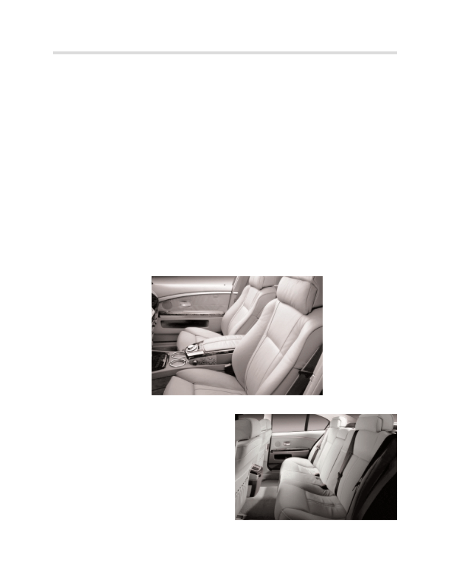
The E65 can be equipped with several different seat versions.
Front Seat Versions
The front seats come in 2 versions:
•
S
Stta
an
nd
da
arrd
d:: 14 way Basic Seat (12 way passenger), electrically adjustable with memory
and 4 way lumbar. The head-restraints of the basic seat are not separately adjustable;
they are controlled by a cable mechanism automatically when the seat is moved forward
or backwards. This allows the head restraint to always be in the optimum position for
safety. Seat heating is available as a stand alone option or part of the cold weather
package
•
O
Op
pttiio
on
na
all a
ac
cttiiv
ve
e s
se
ea
att p
pa
ac
ck
ka
ag
ge
e:: 20 way Comfort Seat with memory, 4 way lumbar, seat
ventilation and active seat feature. The head restraints are controlled automatically with
forward/backward movement of the seat. However, positioning is done electrically and
it allows separate electric adjustment of the head restraint. Seat heating is also avail-
able for the comfort seat as a stand alone option or part of the cold weather package.
Rear Seat Versions
The E65 comes equipped only with the basic
rear seat. Head restraint adjustment is auto-
matic if equipped with the rear safety package.
The rear seats will have optional rear heating
available as part of the cold weather package.
There will be a comfort seat with memory for
the rear when the E66 745Li is introduced later.
4
Seat, Mirror and Steering Column Functions
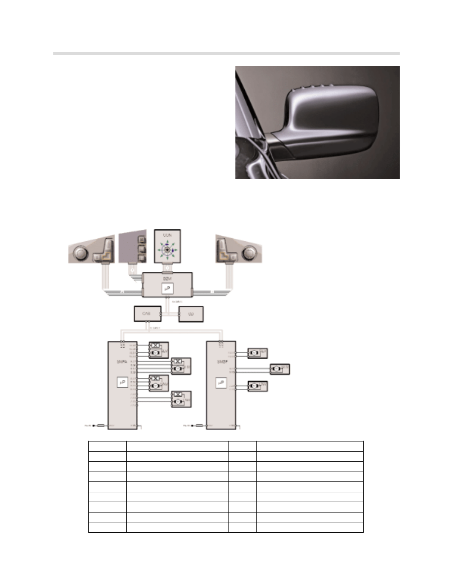
Exterior Rearview Mirrors
The exterior rearview mirrors are electrically
adjustable and heated. They are also
equipped with electro-chromatic auto dim-
ming and are part of the seat memory system.
Steering Column Adjustment
Steering-column adjustment is fully electric.
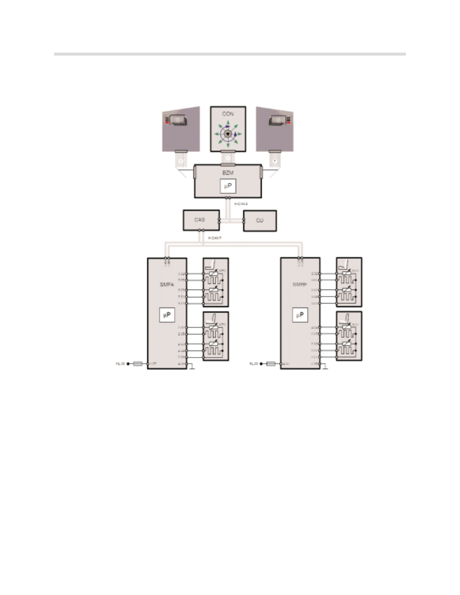
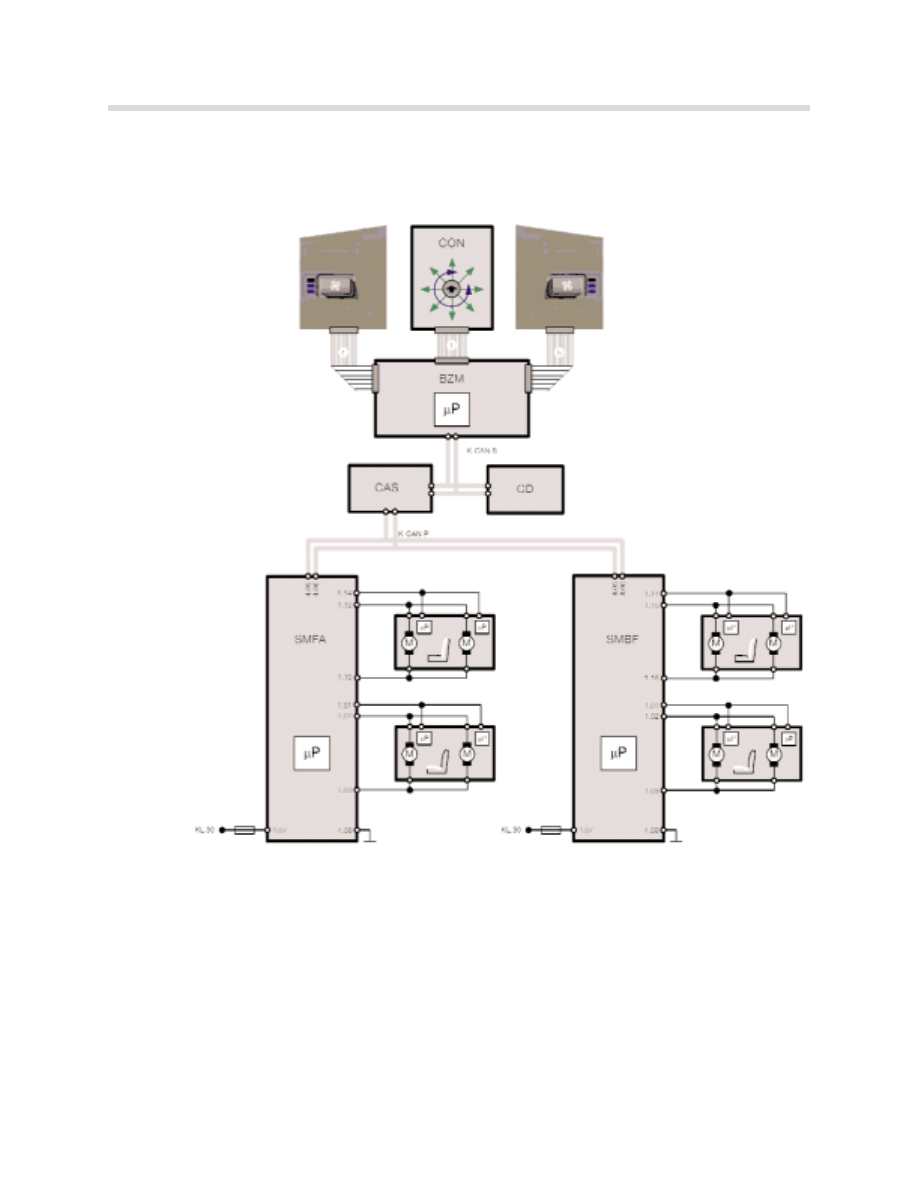
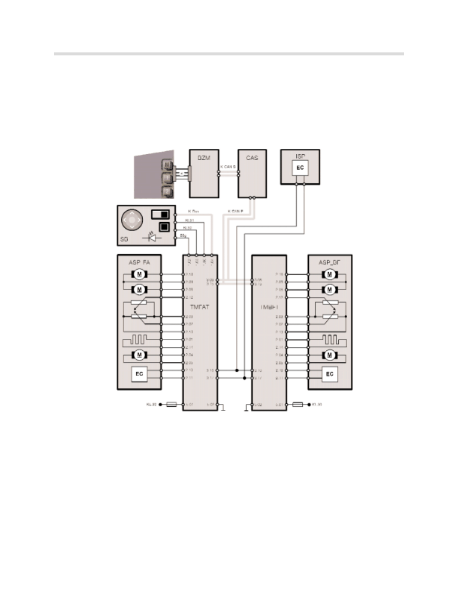
System Overview
Block Diagram: Basic seat
Lumbar components are not shown.
kt-8722
Index
Description
Index Description
BZM
Center console control center
SLV
Longitudinal seat adjustment
CON
Controller
SHV
Seat height adjustment
CAS
Car Access System
SNV
Seat inclination adjustment
SMFA
Seat module drivers side
LNV
Backrest inclination adjustment
SMBF
Seat module passenger side
1
16 pin ribbon cable
K-CAN-S K-CAN-System
2
12 pin ribbon cable
K-CAN-P k-CAN-Periphery
3
12 pin ribbon cable
KL 30
Terminal 30
4
14 pin ribbon cable
5
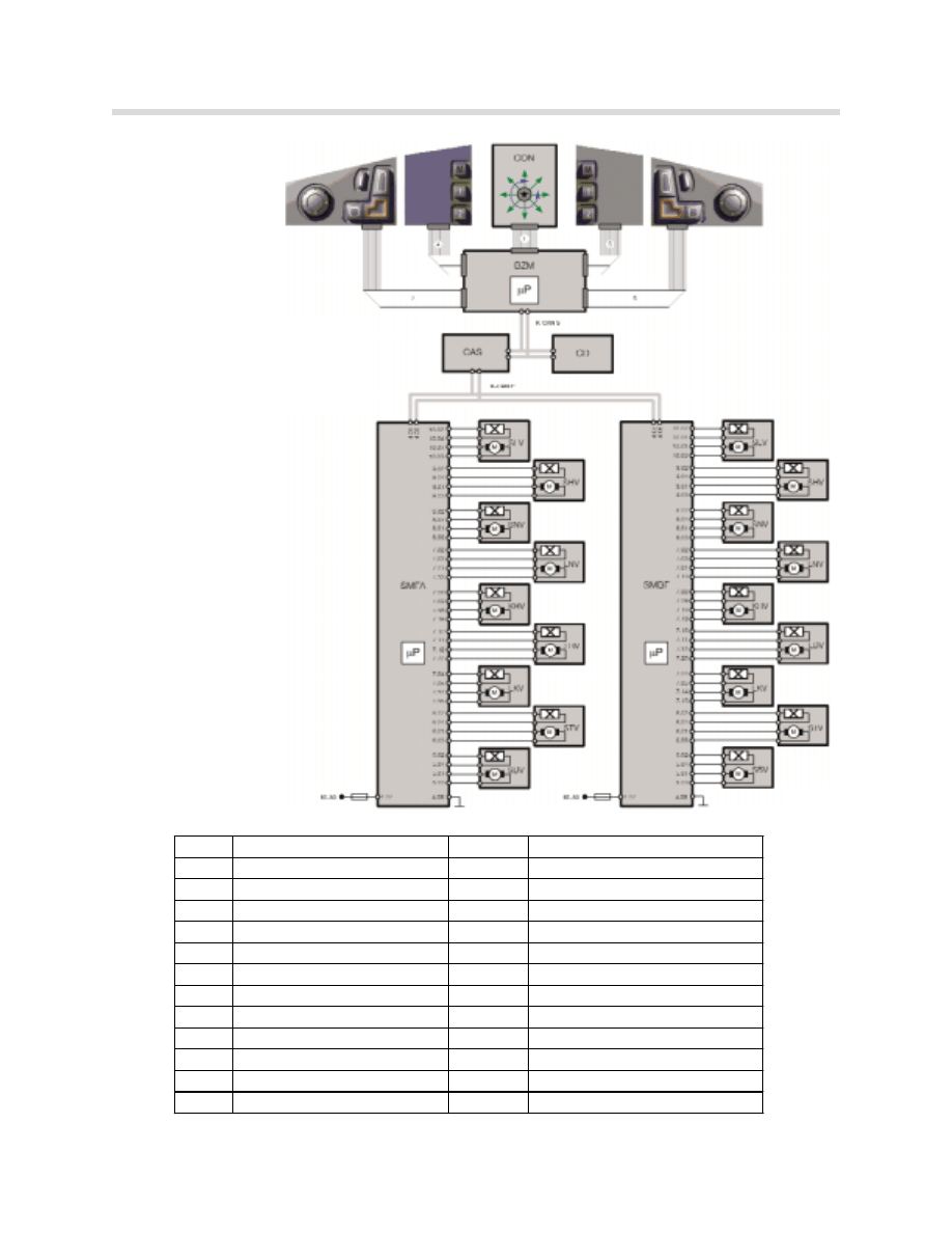
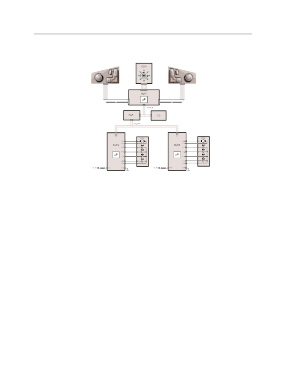
Seat, Mirror and Steering Column Functions
Block Diagram: Comfort seat.
Lumbar, ventilation and active seat
components are not shown.
kt-8734
Index Description
Index
Description
BZM
Center console control center K-CAN-S K-Can System
CON
Controller
K-CAN-P K-CAN Periphery
CAS
Car Access System
1
16 pin ribbon cable
CD
Control Display
2
12 pin ribbon cable
SMFA Seat module, drivers side
3
12 pin ribbon cable
SMBF Seat module, passenger side
4
14 pin ribbon cable
KL 30 Terminal 30
5
14 pin ribbon cable
SLV
Longitudinal seat adjustment
LNV
Backrest inclination adjustment
SHV
Seat height adjustment
LBV
Backrest width adjustment
SNV
Seat inclination adjustment
LKV
Backrest head adjustment
STV
Seat cushion adjustment
KHV
Head restraint height adjustment
SBV
Seat width adjustment
6
Seat, Mirror and Steering Column Functions
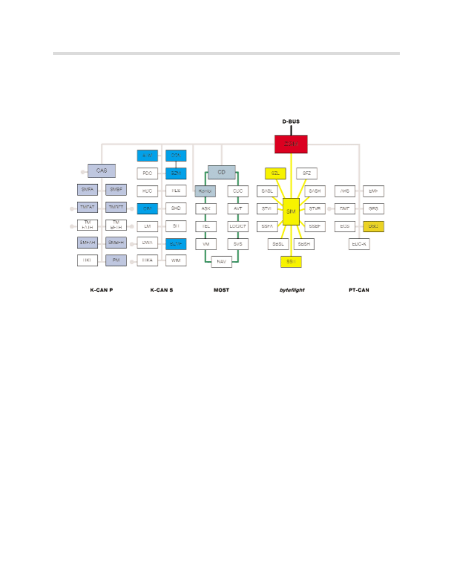
System Interface
The variety of comfort functions are distributed to various control units. Communication
between the relevant control units is conducted by way of the bus, especially to carry out
the memory functions.
Components
Component overview:
•
Switch block, driver and passenger side
•
Center console Control Center (BZM)
•
Car Access System (CAS as gateway))
•
Seat module, driver and passenger side (SMFA/SMBF)
•
Seat-adjusting motors (memory seats include hall sensors for position detecting)
•
Air pump, bladders and solenoids for lumbar support
Additional equipment for comfort seats:
•
Active seat unit per seat
•
9 smart fans per seat for seat ventilation
Optional equipment for basic or comfort seats:
•
Seat heating elements
kt-8676
7
Seat, Mirror and Steering Column Functions
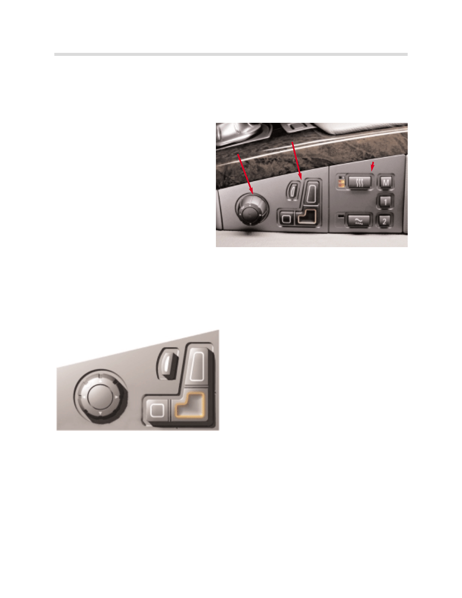
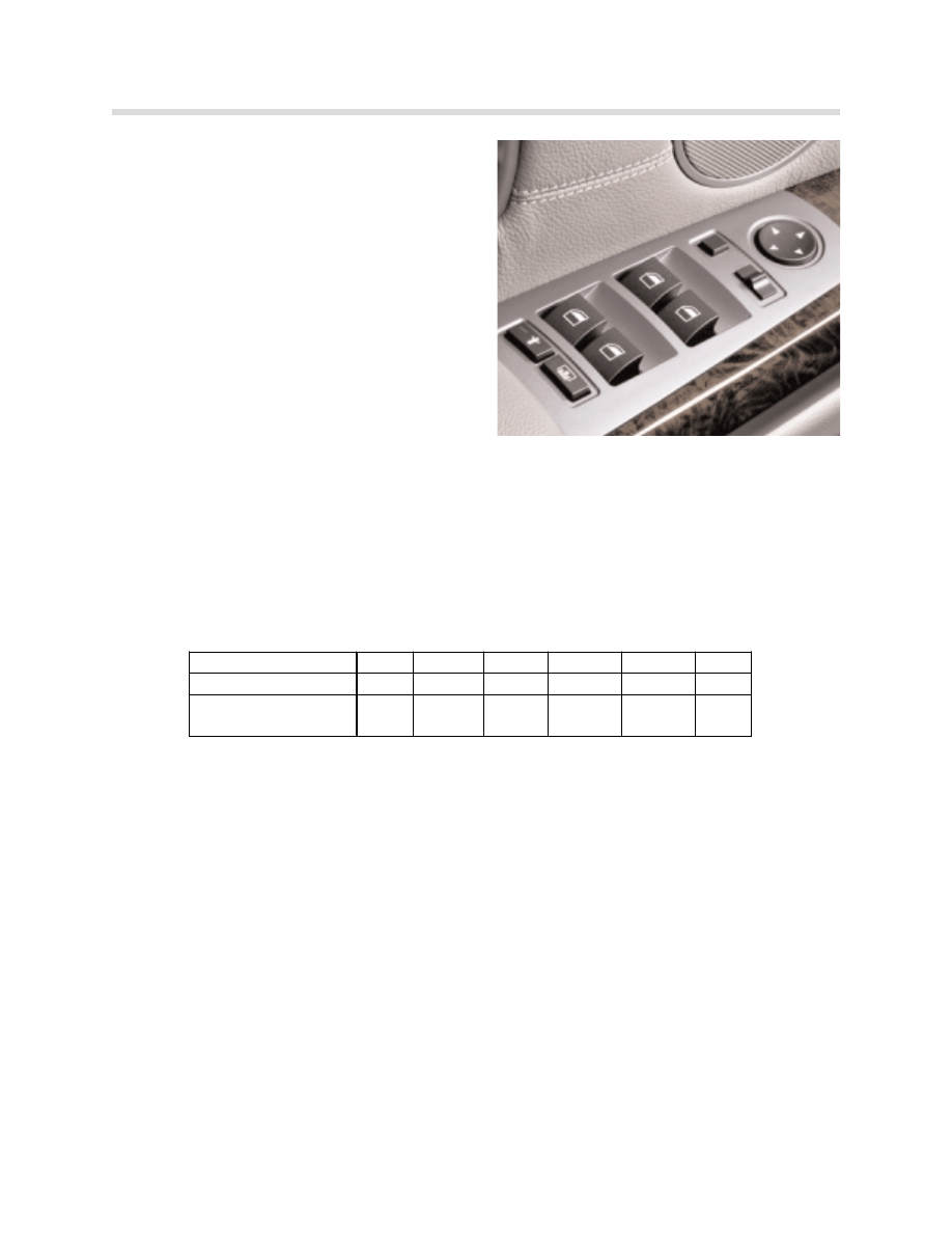
Switch Block, Driver and Passenger
The controls for the driver and passenger seat have been relocated from the seat side panel
and are now part of the center console. The switch block consists of two separate switch
assemblies.
The forward switch assembly contains a
control knob and menu buttons in the
shape of a seat for function selection.
The rearward switch assembly contains
the memory function buttons and possi-
bly three more features:
•
Seat heating control
•
Seat ventilation control
•
Active seat control
LEDs indicate the operating status of each particular seat auxiliary function.
The adjustment request is transmitted from the switch block via ribbon cables to be
processed by the BZM.
1.
Selection button for Lumbar and back-width
adjustment (comfort seat).
2.
Selection button for shoulder tilting (comfort
seat), backrest inclination and head-restraint
height (comfort seat) adjustment.
3.
Selection button for forward/back (longitudi-
nal) seat height and backrest inclination
adjustment.
4.
Seat cushion tilting, Thigh support.
The selected menu button lights up to confirm the request
The control knob is a “joystick” that can be pushed or rotated. It is used to control whichev-
er portion of the seat has been selected using the menu buttons.
The operation of the memory and auxiliary seat function buttons is discussed separately in
“Principle of Operation”.
Control knob
Menu buttons
Memory and auxiliary
seat function buttons
kt-8636
Switch Operation
3
2
4
1
8
Seat, Mirror and Steering Column Functions
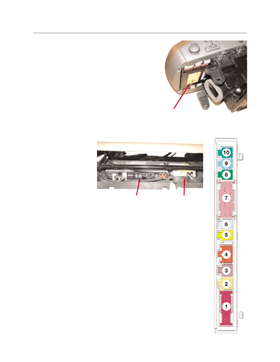
Center Console Control Center (BZM)
The BZM is located in the center console direct-
ly below the Controller. The BZM interprets the
signals from the seat blocks and makes the
message available to the CAS on the K-CAN-
System.
The CAS as the gateway, forwards the mes-
sages to the K-CAN-P where they can be
received by the seat modules.
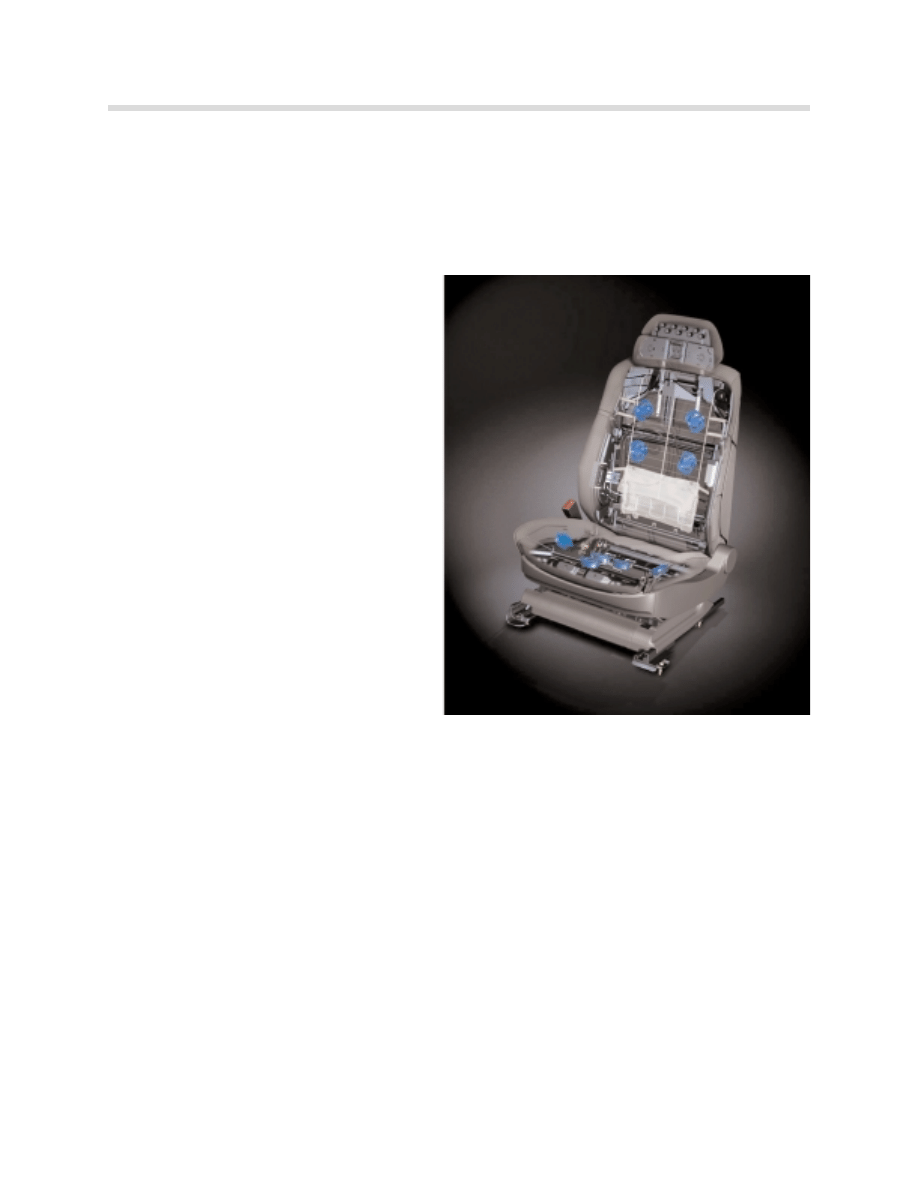
Seat Modules (SMFA, SMBF)
The Seat Modules are
located below the driver’s
and passenger’s seat
next to the seat satellites.
They are clipped into a
plastic carrier. The Seat
Modules have 10 con-
nectors
Both the driver’s and passenger’s seat modules are identical. The mod-
ules are recognized by an additional ground on the drivers side module
at pin 2 of X275 (8-pin).
The seat module activates the seat-motors directly via final stages. Up
to 3 motors may be run simultaneously.
The total running time of each adjusting motor is monitored in order to
prevent thermal overloading.
The seats equipped with memory use motors with integral hall sensors
for position detecting.
The position of the mechanical stops is stored on initial operation. In the
following adjustments, the seat stops before this position is reached (soft
stop).
(The soft stop can be overridden if the seat is operated in the same
direction immediately afterwards).
BZM module
Seat module
Seat satellite
9
Seat, Mirror and Steering Column Functions
In the comfort seat, the 4 main seat adjustments are equipped with a smooth startup:
•
SLV: Longitudinal seat adjustment(forward/backward)
•
SNV: Seat-inclination adjustment
•
SHV: Seat-height adjustment
•
LNV: Backrest-inclination adjustment
Principle of Operation
Seat Memory
The seat memory offers the opportunity of storing up to 3 different positions (2 memory pre-
sets and “last position used”) for every Remote Control used.
This means that if 4 Remote Controls have been assigned to the vehicle, up to 12 different
positions can be stored in the individual seat module.
Availability of these 12 positions depends on whether Key Memory is set to “active” or “not
active”. With Key Memory set to ““n
no
ott a
ac
cttiiv
ve
e””, only 3 memory positions are available. They
are assigned to the vehicle irrelevant of the Remote Control being used.
With Key Memory set to ““a
ac
cttiiv
ve
e””, memory presets stored are assigned to the Remote
Control that is currently being identified (memory preset 1 and 2 and the “last position
used”). The number of stored positions then becomes 3 X the number of remote controls
assigned up to a maximum of 4 (12 positions).
The following components are required for the seat-memory function:
•
Memory buttons, driver’s and passenger’s
•
Center Console Control Center (BZM)
•
Car Access System (CAS)
•
Seat module, driver and passenger (SMFA/SMBF)
•
Seat-adjusting motors with a Hall sensor
Remote Control 1
Remote Control 2
Remote Control 3
Remote Control 4
1
2
3
4
5
6
7
8
9
10
11
12
Key Mem.
1
Mem.
2
Key Mem.
1
Mem.
2
Key Mem.
1
Mem.
2
Key Mem.
1
Mem.
2
10
Seat, Mirror and Steering Column Functions
The SMFA/SMBF requires information from the CAS in order to execute the stored seat
positions: Remote Control number and memory buttons (from the BZM).
•
The information is sent from the CAS via the K-CAN P to the seat module.
•
The seat-adjusting motors are then activated accordingly.
When using the Remote Control to unlock the vehicle, the seat automatically moves to the
last position used for that Remote Control.
If an unlocked car is entered and no button of the Remote Control is pressed, the seat
moves to the last position stored once the Remote control is identified by the CAS.
At the same time, the CAS sends the same information to:
•
The front door modules for the mirror-memory position
•
The CIM (Chassis Integration Module) for the steering column memory positions.
Memory Preset buttons
The memory buttons are integrated in the memory/auxiliary function switch block (behind
the adjusting-switch block) and consist of:
•
Pad with 3 buttons (position buttons 1 and 2 and a memory storage button)
•
Indicator LED in memory storage button for memory readiness
Depending on the special equipment fitted, the buttons for the following functions can be
integrated in the switch block:
- Seat heating
- Seat ventilation
- Active seat
The status of the memory button is communicated to the
relevant seat module over the bus system.
Signal path: Button - ribbon cable - BZM - K-CAN-S -
CAS - K-CAN-P - SMFA or SMBF.
The position of the lumbar support cannot be stored.
kt-8679

11
Seat, Mirror and Steering Column Functions
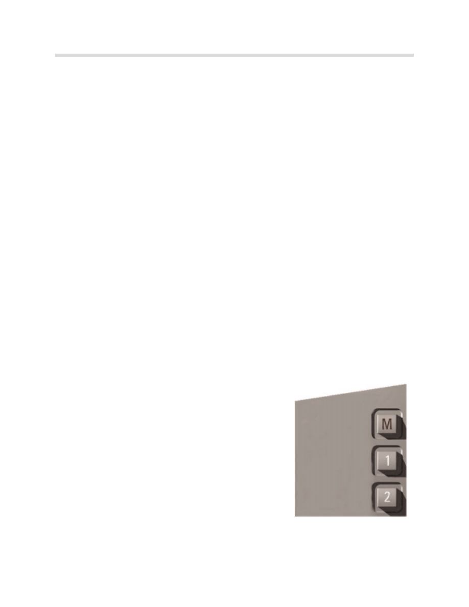
Programming
Programming of seat positions is only possible from terminal R "on".
The following operating steps must be performed in order to store a seat position:
•
Press memory button "M": The memory button lights up to acknowledge programming
readiness.
•
Press position button: adoption of current position of seat, steering column and
side mirrors.
• Programming readiness is deactivated if no position button is pressed within 7 seconds
while it is activated. The function indicator is deactivated.
•
Programming readiness is also deactivated when the memory button is pressed again.
•
If no personalization key is recognized, the programming function is not available when
the key memory is activated.
Calling Up Memory Positions
There are 2 operating modes for calling up stored positions on the driver's seat:
•
One touch mode: touching the desired position button moves the seat automatically up
to the end setting of the stored positions. The one-touch function is only possible with
terminal 15 "off" to eliminate any safety hazard caused by accidental touching of the
button.
•
Continuous hold mode: the seat moves only as long as the desired position button is
continuously pressed. The motors are shut down immediately if the button is released
before the target position is reached. Pressing the position button again resumes the
positioning up to the end setting of the stored position (target position).
12
Seat, Mirror and Steering Column Functions
Seat Heating
Seat heating is an option or part of the cold weather package.
The following components are required for the seat-heating function:
•
Switch block, auxiliary functions, driver and passenger
•
BZM
•
Controller (CON)
•
Control display (CD)
•
Car Access System (CAS)
•
Seat module, driver and passenger (SMFA/SMBF)
•
2 rapid heating elements per seat
•
2 regular heating elements areas per seat
•
4 temperature sensors
kt-8759
13
Seat, Mirror and Steering Column Functions
The switch block contains the control button and 3 orange LEDs. The LEDs indicate the
various heating stages.
The signals for operating the seat heating are transmitted over the buses.
Signal path: Button - 14-pin ribbon cable - BZM - K-CAN S - CAS - K-CAN P - SMFA or
SMBF.
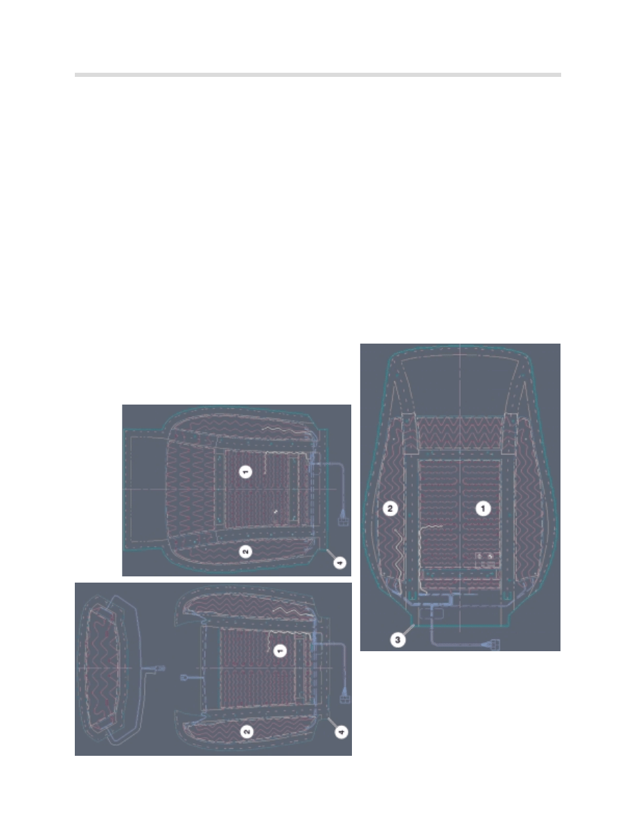
The seat modules incorporate activation and control of seat heating. Each seat has 4 heat-
ing elements, which are sewn into the seat cover:
•
1 rapid heating element in each inner seat cushion area and in inner backrest area.
•
1 residual heating element in each outer seat cushion area and in outer backrest area.
Each heating element is monitored by an NTC temperature sensor.
1.
Rapid heating element
2.
Regular heating element
3.
Backrest cover
4.
Seat cushion cover
kt-9373
kt-9372
kt-9374
14
Seat, Mirror and Steering Column Functions
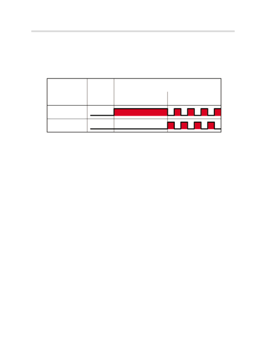
Activation of Heating Areas
When the seat heating is turned on, the rapid heating elements are activated first in order
to heat up the seats quickly.
After the initial rapid heating, the regular heating areas are activated in order to ensure a uni-
form distribution of temperature in the seat.
Activation of all the heating elements is PWM so that an established current intensity is not
exceeded during regular heating. The duty factor is dependent on the selected heating
stage, the ON period and the heating-area temperatures.
The function indicators (LEDs) of the seat heating remain on if the heating is briefly deacti-
vated (e.g. during seat adjustment or by power management).
Operation
The seat heating can be turned on from terminal 15 and the engine running. Stage 3 (max-
imum temperature) is activated when the button is pressed for the first time. Each subse-
quent pressing of the button selects the next stage lower or "off". The seat heating is
turned off if the button is pressed for longer than 1.2 seconds.
The seat heating remains in stand-by (service station feature) for 15 minutes after terminal
15 is switched off.
Seat heating
OFF
Rapid heating
Regular heating
Rapid heating
element
Regular heating
element
ON
kt-8776
15
Seat, Mirror and Steering Column Functions
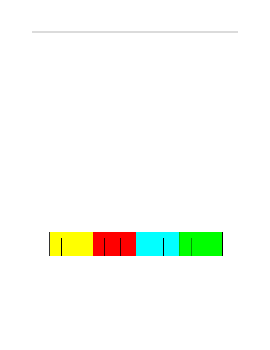
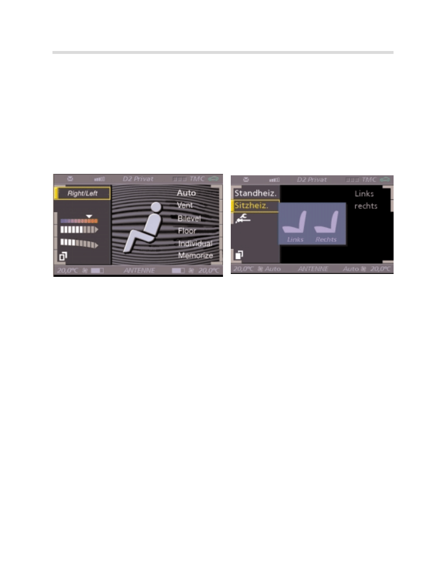
Balance Control
The vehicle occupant can use a balance controller to adjust a temperature differential
between the seat cushion and the backrest up to +/- 3 ºC.
The balance controller can be called up in the Control Display and is set with the Controller.
This setting remains permanently stored specifically to each Remote Control (Key Memory
activated).
For balance control, switch to the Climate menu and call up seat heating from the second
page. Select driver's or passenger seat.
The driver's or passenger seat can be selected in this menu. Turn the Controller to vary the
balance of heat output between the seat surface and the backrest. This change in balance
is indicated by a red/white coloring of the seats in the Control Display.
1.
Select second page from climate menu
3. Select left or right seat
2.
Select seat heating
4. Rotate Controller to vary the ratio of heat
between the backrest and cushion
kt-8686
16
Seat, Mirror and Steering Column Functions
Seat Ventilation
The seat ventilation feature of the comfort seat allows the front seat occupants to cool the
seat cushion and backrest.
The following components are required for the seat ventilation function:
•
Switch block, auxiliary functions, driver and passenger
•
BZM
•
Car Access System (CAS)
•
Seat module, driver and passenger (SMFA/SMBF)
•
9 smart ventilation fans per seat
kt-8760
17
Seat, Mirror and Steering Column Functions
The auxiliary function switch block contains the control button and 3 LEDs for displaying
the ventilation stage.
The signals for operating the seat ventilation are transmitted over the buses.
Signal path: Switch block - 14-pin ribbon cable - BZM - K-CAN S - CAS - K-CAN P - SMFA
or SMBF.
The relevant seat module activates and
monitors the fans. The fans:
•
Are activated by the seat modules
supplying voltage.
•
Can be activated separately for back
rest and seat cushion.
•
Can be operated in 2 speed stages
(high and low) via a control/diagnosis
line.
•
Indicate possible jamming for diagno-
sis over the control/diagnosis line.
Fault code only identifies whether the defective fan
is in the backrest or the cushion it does not identi-
fy individual fan motors.
Operation
The seat ventilation can be turned on from KL 15 "on" and the engine running.
Seat ventilation has 3 stages but only two fan speeds:
•
Stage 3: High speed backrest, high speed cushion (seat bottom)
•
Stage 2: low speed backrest, high speed cushion
•
Stage 1: low speed backrest, low speed cushion
Stage 3 is activated when the button is pressed for the first time. Each subsequent press-
ing of the button selects the next stage lower or "off". The seat ventilation is turned off if the
button is pressed for longer than 1.2 seconds.
The system switches down automatically from stage 3 to stage 2 after an running time of
15 minutes. The ventilation remains in stand-by for 15 minutes after KL R off is received.
18
Seat, Mirror and Steering Column Functions
Lumbar Support
Both seat versions are available with pneumatic lumbar adjustment as standard equipment.
The following components are required for the lumbar support function:
•
Switch block, auxiliary functions, driver and passenger
•
BZM
•
Car Access System (CAS)
•
Seat module, driver and passenger (SMFA/SMBF)
•
2 inflatable air chambers (bladders) and 2 solenoids per seat
•
1 air pump per seat
Operation
Lumbar adjustment is performed by 2 inflatable chambers (air bladders) in the backrest.
The air chambers are inflated and deflated by 2 solenoid valves. The air pump delivers the
required air pressure.
The air pump and the actuators are activated by the seat module based on the commands
from the seat switch block.
The signals for operating the lumbar support are transmitted over the buses.
Signal path: Switch block - 12-pin ribbon cable - BZM - K-CAN S - CAS - K-CAN P - SMFA
or SMBF.
kt-8763
19
Seat, Mirror and Steering Column Functions
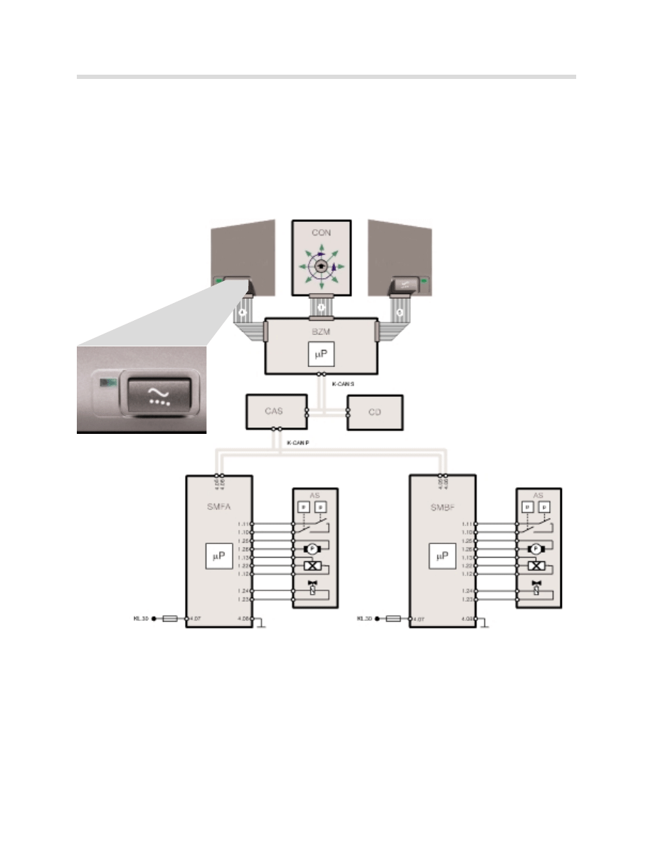
Active Seat
The active seat was introduced for the first time in the E38 for model year '99. The active
seats in the E65 have been adapted to the E65 electrical system.
The active seats relieve the back muscles and spinal column on longer journeys. The seat
cushion of the active seat is moved up and down in stages. For safety reasons, the active
seat is paused when the vehicle is cornering.
The following components are required for the active seat function:
•
Switch block, auxiliary functions, driver and passenger
•
BZM
•
Car Access System (CAS)
•
Seat module, driver and passenger (SMFA/SMBF)
•
1 active seat unit per seat
kt-9354

20
Seat, Mirror and Steering Column Functions
The signals for operating the active seat are transmitted over the buses.
Signal path: Switch block, auxiliary functions, active seat - 14-pin ribbon cable - BZM - K-
CAN S - CAS - K-CAN P - SMFA or SMBF.
Functional Description
The system is filled with a glycol fluid. This fluid is pumped alternately into the left and right
fluid bags (by reversing the direction of pump rotation).
The following components are required for the active-seat function:
•
H
Hy
yd
drra
au
ulliic
c p
pu
um
mp
p:: the hydraulic-pump motor is activated with alternating polarity by semi
conductors in the seat module.
•
H
Ha
allll s
se
en
ns
so
orr:: a Hall sensor records the revolutions of the hydraulic-pump motor. The
motor function is monitored with this signal.
•
S
So
olle
en
no
oiid
d v
va
allv
ve
e:: the solenoid valve is installed between the two fluid bags and opens and
closes the delivery to the fluid bags. The valve is activated by semiconductors in the
seat module. The solenoid valve is closed when the system is deactivated and in the
intervals between the adjustments. In order not to irritate the driver when cornering fast,
the operational sequence of the active seat is stopped immediately at high transversal
acceleration: the solenoid valve remains closed from a specific transversal vehicle
acceleration. The yaw-rate sensor telegrams the transversal-acceleration signal
via the bus system.
•
V
Va
ac
cu
uu
um
m s
sw
wiittc
ch
h:: a vacuum switch is installed in each of the fluid bags. These switches
identify the extent to which the fluid bags are drained. In the event of a fault, the
system stops or holds in order to avoid further damage.
21
Seat, Mirror and Steering Column Functions
Exterior Rearview Mirrors
2 electric rearview mirrors are fitted on the driver's and passenger doors of the E65. They
are activated by the front door modules.
All the mirror functions are controlled by the buttons in the switch block in the driver's door.
The mirrors are directly controlled by the associated door module.
The following functions are possible:
•
Horizontal and vertical mirror adjustment
•
Mirror heating
•
Automatic curb view
•
Mirror memory
•
Electro-chromatic
•
Under-voltage deactivation
kt-8791
22
Seat, Mirror and Steering Column Functions
Horizontal and Vertical Mirror Adjustment
Both the exterior mirrors can be moved in the
horizontal and vertical directions. However,
they can only be adjusted in each case in one
direction (horizontal/vertical).
Each exterior mirror accommodates 2 adjust-
ing motors: one motor for each adjusting direc-
tion. Potentiometers are fitted for position
detection.
A common control pad for both exterior mirrors
is located in the driver's door.
The driver uses a slide switch to select between the two mirrors (right/left).
Mirror Heating
The function of the mirror heating is automatically controlled. The mirror heating is supplied
via PWM signal.
The current output is dependent on outside temperature and wiper operation. The outside
temperature and wiper operation are delivered via the K-CAN.
The heat output is increased in wiper mode in order to make any raindrops on the mirrors
evaporate.
When the wiper is deactivated, the higher percentage ON period remains active for a fur-
ther 5 minutes. The mirror heating is operational from terminal 15 "on". It is deactivated
with terminal 50 "on" (load deactivation during the starting sequence).
The mirror heating is deactivated with priority 4, 5 and 6 for the function "Optimum charg-
ing of Power Module" (see Power Management chapter).
•
Cut-off voltage: 10.8V
•
Cut-in voltage: 11.6V
Temperature in C
<-10
-10 to 5 5 to 15 15 to 25 25 to 35
> 35
Percentage ON period 100%
100%
75%
25%
0%
0%
Percentage ON period
with wiper actuation
100%
100%
75%
50%
25%
0%

23
Seat, Mirror and Steering Column Functions
Automatic Curb View
When the vehicle is being reversed, the passenger mirror is moved downward in order to
provide a better view of the curb. Conditions needed are:
•
The exterior-mirror selector switch for operating the driver's mirror is selected.
•
Terminal 15 "on"
•
Reverse gear is selected
Signal path: EGS - PT-CAN - ZGM - K-CAN S - CAS - K-CAN P - door module.
•
Delay time: 1 second after selection of reverse gear (in order to avoid unnecessary
activation of passenger mirror when reverse gear is accidentally selected).
The passenger exterior mirror immediately reassumes its original position:
•
After the reverse gear has been deselected
•
or with terminal 15 "off".
Manual mirror adjustment is disabled until the mirror reaches its initial position.
Mirror Memory
The mirror-memory function is part of the seat-memory function. The current mirror set-
tings on the driver and passenger sides can be stored or mirror settings already stored can
be re-called using the memory buttons in the vehicle and the Key-Memory function.
The memory positions are stored in the driver's/passenger’s door modules.
The potentiometers for position detection are supplied by the door modules with a voltage
of 5 V. The potentiometers are deactivated in sleep mode.
The various mirror-adjustments have different priorities.
•
Manual mirror adjustment has priority over all other mirror adjustments. Manual mirror
adjustment interrupts any memory adjustment.
•
Mirror adjustment by means of the buttons of the memory function has priority over
mirror adjustment by means of the Key Memory:
A mirror activation in progress which has been initiated by the Key Memory is cancelled
when the memory buttons are operated.

24
Seat, Mirror and Steering Column Functions
Electro-chromatic Exterior Rearview Mirrors
Electro-chromatic exterior rearview mirrors ensure that the driver is not dazzled by the
headlights of vehicles from behind.
The exterior mirrors are automatically dimmed when a light source coming from the rear is
detected. The sensor and control electronics for this function are integrated in the inside
rearview mirror.
•
A photo sensor in the inside rearview mirror measures the amount of light coming from
the rear of the vehicle as opposed to the front.
•
The control electronics calculates the amount of dimming required for this incidence of
light. Stronger or weaker dimming of the exterior mirrors is performed depending on
the degree of potential dazzling.
The control signals are transmitted from the inside rearview mirror via the front door mod-
ules to the exterior mirrors.
Under-voltage Deactivation
Under-voltage deactivation ensures that primary electrical-system functions take priority
over the mirror functions.
The supply voltage is monitored locally in the door modules. All the mirror functions are dis-
abled if the supply voltage drops below 8.5 V.
Once the voltage has dropped below this limit, the mirror functions are not available again
until system voltage increases over 9 V.
25
Seat, Mirror and Steering Column Functions
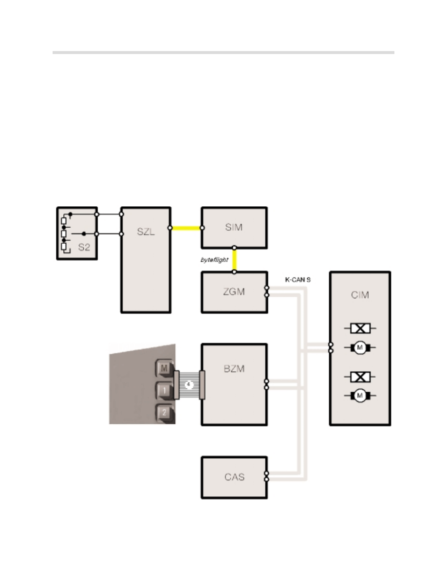
Electric Steering-Column Adjustment
The electrically adjustable steering column is adjusted (inclination and length) with the steer-
ing-column adjusting switch on the left side of the steering-column cover.
Electric adjustment of the steering column is effected by the Chassis Integration Module
(CIM). The CIM controls the motor gearbox unit for adjustment.
The motors are activated internally by a power semiconductor. The steering column is
moved into the upmost position for entry and exit purposes (automatic entry facility).
kt-9368
S2: Steering
column control
knob

26
Seat, Mirror and Steering Column Functions
Automatic Entry
The electrically adjustable steering column is moved into the upper-most position for entry
and exit purposes. The automatic entry facility is activated when:
•
Terminal 15 "off" and terminal R "off".
•
Terminal 15 "off" while driver's door is open.
•
Driver's door is opened after terminal 15 "off", also when terminal R is still activated.
The automatic entry is deactivated when terminal 15 is re-activated; the return position is
approached. Automatic operation stops if the control switch for steering-column adjust-
ment is operated during automatic entry.
The previous return position is overwritten if automatic entry is interrupted by operation of
the steering-column adjustment control switch.
The return position is retained if while the automatic entry is active, the control switch
inputs: "steering column up" (towards headliner) or "steering column forward" (towards
instrument cluster) are operated.
If the memory is called up while automatic entry is active, the memory steering-column
position is assumed only after the automatic entry has been completed. The normal return
position is substituted by the called-up memory position.
Soft Stop
If the steering column reaches a mechanical stop during adjustment, this position is per-
manently stored. Starting out from this value, the adjustment travel for future adjustments
is restricted to eliminate any future mechanical blocking.
This soft stop can be manually overridden if the column is operated in the same direction
immediately afterwards.
Steering-Column Memory
A Hall sensor is fitted in each of the adjusting motors. The Hall sensors record the steer-
ing-column position for the memory functions. 2 different positions can be stored by means
of the seat-memory buttons in the switch block.
The memory positions are stored in the driver's seat module (SMFA). Automatic operation
stops if the switch for steering-column adjustment is operated during activation of the
memory steering-column position.
27
Seat, Mirror and Steering Column Functions
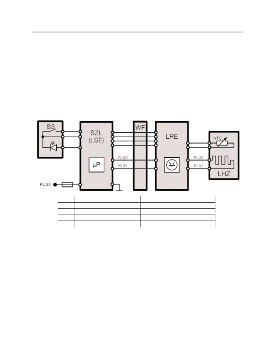
Steering Wheel Heating
The steering wheel heating is available as an option or as part of the cold weather pack-
age.
It is operational from terminal 15 "on". It is activated and deactivated by pressing the but-
ton on the left side of the steering-column cover. The LED indicator light in the button illu-
minates when the steering wheel heating is activated.
The temperature in the steering wheel is monitored by a sensor and maintained at 36 ºC.
The control electronics are in the SZL. The load current is passed on by the coil spring and
the steering wheel electronics module.
Diagnosis of Steering Wheel Heating
In the event of a fault, the steering wheel heating (LHZ) can no longer be activated (if the
fault is currently present). Faults can only be diagnosed after terminal 15 "on" and an
attempt to activate the steering wheel heating has been made. The following fault memo-
ry entries are available to diagnose the steering-wheel heating:
•
Steering-wheel heating, heating mat, short circuit to terminal 31
•
Steering-wheel heating, heating mat, short circuit to terminal 30
•
Steering-wheel heating, temperature sensor faulty
The resistance value of the temperature sensor can be read out in the Diagnosis Request:
"LHZ status".
kt-8793
Index
Description
Index
Description
S3
Control button
NTC
Temperature sensor
SZL
Steering Column Switch Center
LHZ
Steering wheel heating
WF
Coil spring (contact ring)
LSE
Steering column electronics
LRE
Steering wheel electronics

28
Seat, Mirror and Steering Column Functions
Review Questions
1. Which control unit is responsible for converting the seat switch signals into bus
telegrams and broadcasting them over the bus system? Where is this control unit
located?
2. Up to how many memory positions may be stored in the seat modules? What needs
to set in VKM before all the possible memory locations can be stored?
3. What are the differences in the way seat heating operates and is controlled compared
to the previous model (E38)?
4. Why are the fan motors of the ventilated seats referred to as “smart fans”?
5. Where are the memory positions of the exterior rear view mirrors and the steering
column stored?
Document Outline
- Main Menu
- E65 Introduction
- E66 Body
- E65 Bus Systems
- E65 Power Module
- E65 Car Access System
- E65 iDrive (Driving Area)
- E65 Instrument Cluster
- E65 iDrive (Comfort Area)
- E65 Audio System
- E65 Navigation System
- E65 Telephone
- E65 Speech Processing System
- E65 Intelligent Safety Integration System
- E65 Central Body Electronics
- E65 Remote Control Service
- E65 Automatic Trunk Lid Lift
- E65 Windshield Wiping & Washing
- E65 Seat, Mirror & Steering
- E65 Vehicle Lighting System
- E65 Anti-Theft Alarm System
- E65 Tire Pressure Control
- E65 Park Distance Control
- Active Cruise Control
- ACC Workbook
- E65/66 IHKA
- E66 Rear Air
- Diagnostic Equipment
Wyszukiwarka
Podobne podstrony:
akumulator do seat leon cupra r 18 t 28 v6 24v 4x4
akumulator do seat toledo 1l 18i 18 16v 20i 20i 16v
akumulator do seat altea xl 5p5 18 tfsi 20 fsi 20 tfsi 4wd 1
akumulator do seat ibiza iv 6l1 14 16v 16 16 16v 18 t fr 1
akumulator do seat leon 1m1 18 20v 18t 20v 19 sdi 19 tdi
akumulator do seat ibiza iii 6k1 18 20v
akumulator do seat toledo ii 1m2 14 16v 16 16 16v 18 20v 18
akumulator do seat exon 16 16mpi 18 turb 20 tsi
07 E65 Suspension & Steering
18 John Ashbery, Self Portrait in a Convex Mirror
akumulator do seat exon vario 16 16mpi 18 turb 20 tsi
akumulator do seat alhambra 7v8 18 t 20v 20i
akumulator do seat cordoba cupra 18 t 20v
akumulator do seat altea 5p1 18 tfsi
akumulator do seat toledo iii 5p2 16 18 20 fsi 20 fsi tiptr
akumulator do seat leon ii 1p1 16 16 16 v 18 20v 18 20v t
Prezentacja 18
podrecznik 2 18 03 05
więcej podobnych podstron