
Document Number: EDS 06-0016
Version: 6.1
Date: 31/07/2015
T
H
IS
I
S
A
N
U
N
C
O
N
T
R
OL
L
E
D
D
O
C
U
M
EN
T
,
T
H
E
R
E
A
D
ER
M
U
ST
C
ON
F
IR
M
I
T
S
VA
L
ID
IT
Y
B
EF
OR
E
U
SE
ENGINEERING DESIGN STANDARD
EDS 06-0016
LV NETWORK EARTHING DESIGN
Network(s):
EPN, LPN, SPN
Summary:
This standard details the design requirements for earthing of low voltage (LV)
networks.
Owner:
Allan Boardman
Date:
31/07/2015
Approved By:
Steve Mockford
Approved Date:
11/08/2015
This document forms part of the Company’s Integrated Business System and its requirements are mandatory throughout UK
Power Networks. Departure from these requirements may only be taken with the written approval of the Director of Asset
Management. If you have any queries about this document please contact the author or owner of the current issue.
Circulation
UK Power Networks
External
All UK Power Networks
G81 Website
Asset Management
Contractors
Capital Programme
ICPs/IDNOs
Connections
Meter Operators
HSS&TT
Network Operations
UK Power Networks Services
LV Network Earthing Design
Document Number: EDS 06-0016
Version: 6.1
Date: 31/07/2015
© UK Power Networks 2018 All rights reserved
2 of 27
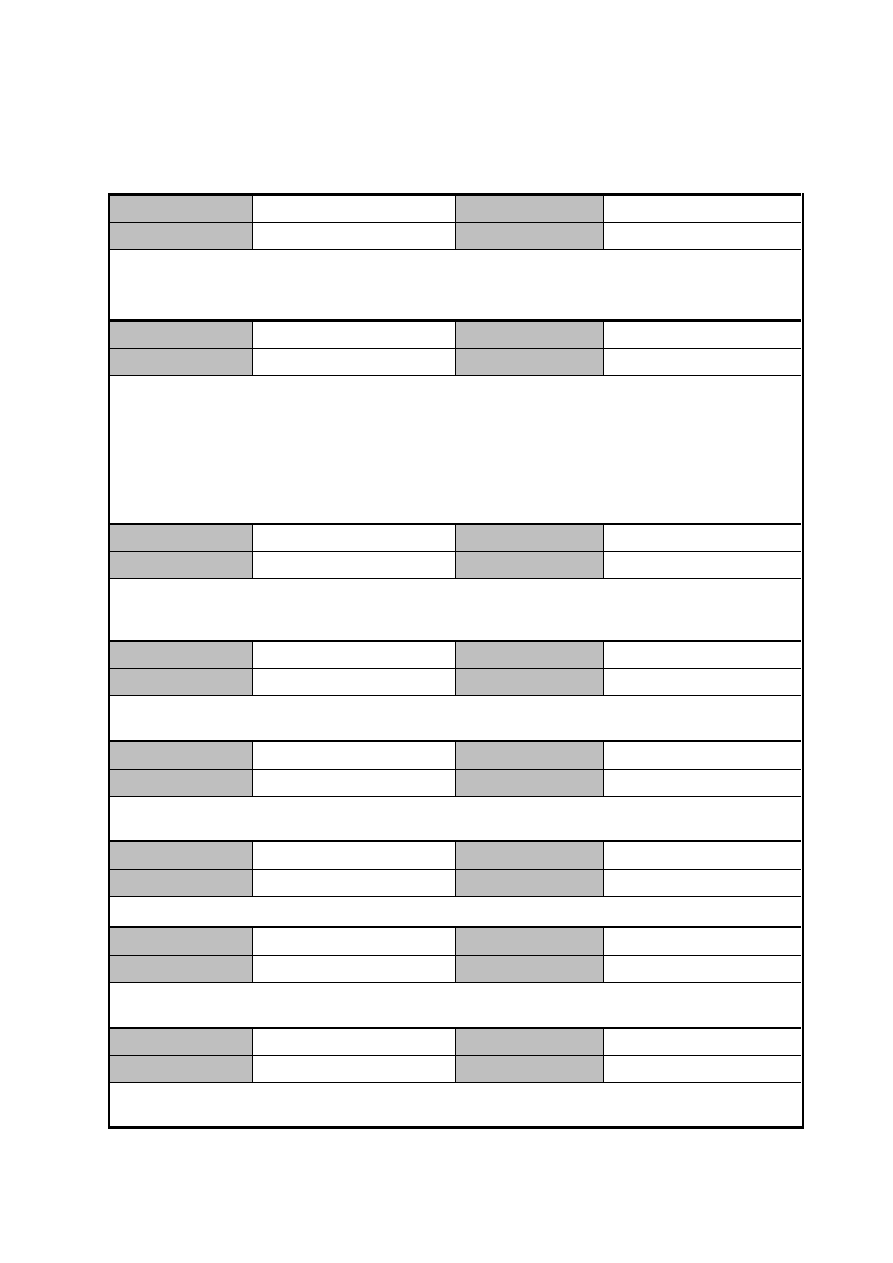
Revision Record
Version
6.1
Review Date
31/07/2019
Date
18/01/2018
Author
Lee Strachan
Why has the document been updated: minor version update
What has changed: following references changes throughout document, EDS 08-0136 to EDS 08-
2000, EDS 08-0129 to EDS 08-2101, EDS 08-0133 to EDS 08-2102
Version
6.0
Review Date
31/07/2019
Date
31/07/2015
Author
Stephen Tucker
Why has the document been updated: Updated to provide consistency with other earthing
standards.
What has changed:
Simplification of neutral conductor earthing requirements (Section 5.2).
Revision of earth electrodes (Section 6.1).
Appendix on typical electrode systems removed as it is covered in ECS 06-0023.
Broken neutral explanation added (Appendix C).
Version
5.0
Review Date
17/01/2017
Date
31/12/2013
Author
Stephen Tucker
Further clarity around the use of additional PME electrodes on underground networks added
(Sections 5.2, 5.3.2 and 5.3.3). Earth resistance value for introducing CNE into SNE networks
changed back to 10
Ω in line with revised ENA ER G12/4 requirements (Sections 5.3.2)
Version
4.0
Review Date
12/04/2018
Date
12/04/2013
Author
Stephen Tucker
Earthing of service joints for PME conversion removed (Section 5.3.3) and legacy cable section
(6.3.4) removed
Version
3.1
Review Date
23/04/2015
Date
06/07/2012
Author
Stephen Tucker
Minor updates to ensure consistency with other standards and greater use of aluminium conductors.
Document reviewed for publishing on G81 website
Version
3.0
Review Date
22/04/2015
Date
17/11/2011
Author
Stephen Tucker
Underground cable sections revised. PNB section added
Version
2.2
Review Date
01/06/2015
Date
29/09/2011
Author
Stephen Tucker
Reclassification of document from Earthing Design Manual Section 6
Version
2.0
Review Date
01/06/2015
Date
01/06/2010
Author
Stephen Tucker
Completely rewritten to provide a more consistent and practical approach. Customer installation
earthing moved to Section 7 of the Earthing Design Manual
LV Network Earthing Design
Document Number: EDS 06-0016
Version: 6.1
Date: 31/07/2015
© UK Power Networks 2018 All rights reserved
3 of 27
Version
1.0
Review Date
31/03/2011
Date
31/03/2008
Author
Stephen Tucker/
Rob Weller
Original

LV Network Earthing Design
Document Number: EDS 06-0016
Version: 6.1
Date: 31/07/2015
© UK Power Networks 2018 All rights reserved
4 of 27
Contents
1
Introduction ............................................................................................................. 6
2
Scope ....................................................................................................................... 6
3
Glossary and Abbreviations ................................................................................... 7
4
LV Earthing Standard .............................................................................................. 9
5
Design Criteria ....................................................................................................... 10
5.1
General Requirements ............................................................................................ 10
5.2
Supply Neutral Conductor Earthing Requirements .................................................. 10
5.3
Underground Cable Networks ................................................................................. 12
5.3.1
New Underground Cable Networks ......................................................................... 12
5.3.2
Converting Existing Underground Cable Networks to PME ...................................... 12
5.3.3
Converting Existing Customers to PME ................................................................... 13
5.3.4
Looped Services ...................................................................................................... 14
5.4
Overhead Line Networks ......................................................................................... 15
5.5
Protective Neutral Bonding (PNB) ........................................................................... 16
5.6
Load Balance .......................................................................................................... 17
5.7
Earth Fault Loop Impedance ................................................................................... 17
6
LV Earthing Requirements .................................................................................... 18
6.1
Earth Electrodes ...................................................................................................... 18
6.2
Bonding Connections .............................................................................................. 18
6.3
Earth Resistance Values ......................................................................................... 19
7
References ............................................................................................................. 20
Appendix A
– ESQC Regulations ..................................................................................... 21
Appendix B
– Earthing Systems ...................................................................................... 23
B.1
IEC Standard for the Naming of Earthing Systems .................................................. 23
B.2
BS 7671 Definitions ................................................................................................. 23
B.3
TN-S (Terre-Neutral Separated) .............................................................................. 24
B.4
TN-C-S (Terre-Neutral-Combined-Separated) ......................................................... 24
B.5
TT (Terre-Terre) ...................................................................................................... 26
Appendix C
– Broken Neutral ........................................................................................... 27

LV Network Earthing Design
Document Number: EDS 06-0016
Version: 6.1
Date: 31/07/2015
© UK Power Networks 2018 All rights reserved
5 of 27
Figures
Figure 5-1
– Supply Neutral Conductor Earthing Requirements for PME ............................ 11
Figure 5-2
– Typical Application of CNE Cables in Existing Networks ................................. 12
Figure 5-3
– PNB Options using CNE and SNE Cut-outs .................................................... 16
Figure 5-4
– PNB for up to Four Customers ........................................................................ 17
Figure B-1
– TN-S Earthing System .................................................................................... 24
Figure B-2
– PME Earthing System ..................................................................................... 25
Figure B-3
– PNB Earthing System ..................................................................................... 25
Figure B-4
– TT Earthing System ........................................................................................ 26
Figure C-5
– Current Flow in a Network Converted to PME due to a Broken Neutral .......... 27

LV Network Earthing Design
Document Number: EDS 06-0016
Version: 6.1
Date: 31/07/2015
© UK Power Networks 2018 All rights reserved
6 of 27
1
Introduction
This standard (previously Section 6 of the Earthing Design Manual) details the earthing design
requirements for low voltage (LV) networks. It supersedes all previous EPN, LPN and SPN
specific guidance on PME network design, and brings together a common approach to system
design and operation.
The standard is based on ENA ER G12/4 and has also reflects the requirements of BS
7671:2008 (2011) incorporating Amendment No 3: 2015 (IET Wiring Regulations Seventeenth
Edition).
Although this standard covers most aspects of LV network earthing there will be some
situations where advice from an earthing specialist is required, refer to EDS 06-0001 for further
details.
The earthing design for secondary distribution substation (including the substation LV earth)
and pole-mounted equipment are covered respectively in EDS 06-0014 and EDS 06-0015.
Earthing associated with customer installations, including the provision of an earth terminal, is
detailed in EDS 06-0017.
This standard is divided into the following sub-sections:
Definitions (Section 3).
LV Earthing Standard (Section 4).
PME Network Design (Section 5).
LV Earthing Requirements (Section 6).
References (Section 7).
Regulations (Appendix A).
LV Earthing Systems (Appendix B).
Significant changes from existing practice or previous versions:
The statutory requirements from the Electricity, Supply Quality and Continuity (ESQC)
regulations 2002 are included in the text.
The guidance from the latest draft of ENA G12/4 is included.
The requirements from BS 7671:2008 (2011) are included.
The additional PME earth electrode requirements, at each branch and service joint,
introduced in version 1 of this standard have been removed as they are deemed
unnecessary for modern cables and current network construction.
The electrodes, bonding conductors and labels have all been reviewed.
All earthing requirements for LV customer installations including the provision of PME
terminals and special situations have been removed and are now included in
EDS 06-0017.
The use of protective neutral bonding (PNB) for specific applications is reinstated.
2
Scope
This standard applies to the earthing design for all new LV networks and existing LV networks
where a material alteration is to take place.
This document is intended for internal and external use.

LV Network Earthing Design
Document Number: EDS 06-0016
Version: 6.1
Date: 31/07/2015
© UK Power Networks 2018 All rights reserved
7 of 27
3
Glossary and Abbreviations
1
Term
Definition
CNE
Combined Neutral and Earth. A cable where the neutral and protective
functions are combined in a single conductor
Customer/Consumer
Any person who has responsibility for premises connected by agreement to
distribution networks owned by UK Power Networks
Customer's Installation
The electrical apparatus under the control of the customer on the
customer
’s premises together with the wiring connecting this apparatus to
the supply terminals. A cut-out and meter shall not form part of the
customer’s installation (unless additional metering is supplied by the
customer, e.g. landlord’s supplies)
Customer's Premises
Any area or building occupied by the customer
Distributing Main (or
Main)
A low voltage electric line which connects a source of voltage to one or
more service lines or directly to a single customer
’s installation
Distributor*
A person who owns or operates a network, except for a network situated
entirely offshore or where that person is an operator of a network within the
meaning of Part I of the Railways Act 1993
DNO
Distribution Network Operator. See distributor
Earth Electrode
A metal rod, plate or strip conductor buried in the earth for the purpose of
providing a connection with the general mass of earth
Earth Loop Impedance
(ELI)
See Earth Fault Loop Impedance
Earth Fault Loop
Impedance (EFLI)**
The impedance of the earth fault current loop starting and ending at the
point of earth fault. This impedance is denoted by the symbol Zs. The part
of the earth fault loop impedance which is external to the customer
installation is denoted by the symbol Ze.
Earthing Systems
See separate definitions and Appendix B for further details
Earthing Terminal
The main earth terminal for an installation is usually located close to the
incoming service. If provided by UK Power Networks as part of a PME
supply (TN-C-S) this will be directly connected to the supply neutral
conductor at the supply terminals
EMC
Electromagnetic Compatibility
EPR
Earth Potential Rise (EPR) or Rise of Earth Potential (ROEP). EPR or
ROEP is the potential (or voltage) rise that occurs on any metalwork due to
the current that flows through the ground when an earth fault occurs on the
HV or LV network
Electric Line*
Any line which is used or intended to be used for carrying electricity for any
purpose and includes, unless the context otherwise requires:
a) any equipment connected to any such line for the purpose of carrying
electricity.
b) any wire, cable, tube, pipe, insulator or other similar thing (including its
casing or coating) which surrounds or supports, or is associated with, any
such line
1
*Definitions taken from the Electricity Safety, Quality and Continuity Regulations 2002.
**Definitions taken from BS 7671.

LV Network Earthing Design
Document Number: EDS 06-0016
Version: 6.1
Date: 31/07/2015
© UK Power Networks 2018 All rights reserved
8 of 27
Term
Definition
IDNO
Independent Distribution Network Operator
Inset Network
Privately owned electricity supply network, owned and operated by a
licensed Independent Distribution Network Operator (IDNO), supplied at a
boundary point or points from the DNO network
Low-voltage (LV)
LV refers to any voltage less than 1000V. The LV network refers to the
400V distribution system
Multi-service
Any electric line through which energy may be supplied to two, three or four
adjacent customers from any distributing main or substation
NetMap
UK Power Networks graphical information system (GIS)
Protective Multiple
Earthing (PME (TN-C-S)
Protective Multiple Earthing is the most common form of earthing provided
at new installations. A single conductor for neutral and earthing functions is
utilised and an earth terminal is provided at the customer’s installation. The
customer’s earthing may be connected to this terminal providing the
relevant requirements in BS 7671 are satisfied. In some cases it is not
appropriate to provide a PME earth terminal, either due to the nature of the
distribution system or due to the type of installation itself
Residual Current Device
(RCD)
An RCD is a current operated device which measures the imbalance
between phase and neutral currents, and if this leakage current exceeds a
pre-set level will operate to interrupt the current flow. Typical domestic
RCDs have a 30mA operating threshold
ROEP
Rise of earth potential. See EPR
Secondary (Distribution)
Substation
An HV/LV substation typically transforming 22kV, 20kV, 11kV or 6.6kV to
400V
SNE
Separate Neutral and Earth. A cable where the neutral and protective
functions are provided by separate conductors
Service Line*
Any electric line which either connects a street electrical fixture, or no more
than four customers’ installations in adjacent buildings, to a distributing
main
Service
See Service Line
Service Termination
The cut-out where the service cable terminates
Street Electrical Fixture*
A permanent fixture which is or is intended to be connected to a supply of
electricity and which is in, on, or is associated with a highway
Supplier*
A person who contracts to supply electricity to consumers
TN-C-S
See PME
TN-S
See Cable Sheath Earth/Separate Continuous Earth Wire
TT
Independent local or TT earthing is common in older installations and is
also used where PME cannot be provided. An earth terminal is not provided
and the customer is responsible for providing the earth electrode system
(typically buried earth rods and/or conductor). Where local earthing is
employed the installation normally has to be protected by a residual current
device (RCD) in order to comply with BS 7671
UK Power Networks
(Operations) Ltd
UK Power Networks (Operations) Ltd consists of three electricity distribution
networks as follows:
Eastern Power Networks plc (EPN)
London Power Network plc (LPN)
South Eastern Power Network plc (SPN)

LV Network Earthing Design
Document Number: EDS 06-0016
Version: 6.1
Date: 31/07/2015
© UK Power Networks 2018 All rights reserved
9 of 27
4
LV Earthing Standard
The Electricity Safety, Quality and Continuity Regulations 2002 (24(4)) (refer to Appendix A)
state that a distributor shall make an earthing terminal available when installing a new low
voltage connection or replacing an existing connection, unless it is inappropriate for reasons
of safety.
UK Power Networks' standard is to provide an earth terminal from a PME system wherever it
is appropriate to do so. EDS 06-0017 (Customer LV Installation Earthing Design) details the
situations where it may be inappropriate to provide an earth terminal from a PME system.
Therefore all new low voltage mains and services shall be constructed to PME standards
described in Section 5 using combined neutral earth (CNE) cables and overhead lines to
enable an earth terminal to be provided.
Whenever major work (e.g. refurbishment, diversion etc.) is carried out on the low voltage
distribution network, it shall be brought up to PME standards where appropriate, as described
in Section 5.
Generally only one service and earth terminal shall be provided to a customer or a building.
Multiple services to a single customer or building are not recommended practice since this
causes problems due to neutral current diversion
2
and uncertainty when isolating the supplies.
Refer to EDS 06-0017 for further information on multiple supplies.
2
Out of balance three-phase loads and single-phase loads cause current to flow in the neutral conductor. Neutral
current diversion occurs when multiple PME supplies are provided to the same building and an alternative path
exists, for example through the structural steelwork of a building and an earth bond, to the other neutral/earth
terminal. The natural passage of neutral current through the structural steelwork can give rise to magnetic field
problems both close to the steelwork and at the source which may cause EMC issues etc. Furthermore,
equipotential bonding conductors may carry neutral current resulting in overheating and consequential fire risk.
Refer to EDS 06-0017 for further information.

LV Network Earthing Design
Document Number: EDS 06-0016
Version: 6.1
Date: 31/07/2015
© UK Power Networks 2018 All rights reserved
10 of 27
5
Design Criteria
This section describes the requirements for PME networks and is split into the following
sub-sections:
General requirements.
Supply neutral conductor earthing.
Underground cable networks.
Overhead line networks.
Load balance.
Protective neutral bonding (PNB).
Earth fault loop impedance.
5.1
General Requirements
The following general requirements apply to all new and existing low voltage networks to
enable PME to be used:
For combined HV and LV earthing systems, the earth potential rise (EPR) at the secondary
substation supplying the PME network shall not exceed 430V during a HV earth fault. If
the EPR exceeds 430V the HV and LV earthing systems shall be segregated. Refer EDS
06-0014 for further details on secondary substation design.
Protective devices shall not be included in the supply neutral conductor or any earthing
connection to ensure they are permanently connected.
The integrity of the supply neutral conductor shall be maintained throughout the network
and should be considered during the design, construction, maintenance and operation of
the distribution system.
The supply neutral conductor shall be connected to earth (or the supply neutral conductor
of another main) at other points throughout the network in addition to the LV earth at or
near to the secondary substation (refer to Section 5.2).
The resistance of the supply neutral conductor to the earth shall not exceed 20Ω at any
point (refer to Section 6.3).
Loads shall be shown uniformly distributed across the phases along a main at the design
stage (refer to Section 5.5).
5.2
Supply Neutral Conductor Earthing Requirements
In addition to the main LV neutral earth at or near the substation, the supply neutral conductor
shall be connected at other points to earth electrodes, or to the supply neutral conductor of
another main to ensure that the resistance of the supply neutral conductor does not exceed
20
Ω at any point on the network.
The additional earth connections will also ensure that the potential of the supply neutral
conductor is as close to that of true earth as possible, and provide resilience against open-
circuit neutral conditions, therefore reducing the likelihood of the neutral rising to undesirable
voltage levels (refer to Appendix C). This means that the combined neutral/earth conductor
will be earthed at multiple locations.
LV Network Earthing Design
Document Number: EDS 06-0016
Version: 6.1
Date: 31/07/2015
© UK Power Networks 2018 All rights reserved
11 of 27
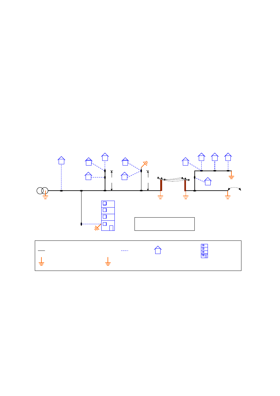
The additional neutral earth electrodes are illustrated in Figure 5-1 and shall be installed as
follows:
In the pot-end at the end of each main. Alternatively, connecting the supply neutral
conductor to that of another main with a separate path back to the substation will serve
the same purpose.
In the pot-end at the end of any branch or service supplying more than four customers.
In the pot-end at the end of any branch or service supplying more than one customer and
longer than 40m.
In the pot-end at the end of any branch or service supplying street furniture with a PME
earth terminal.
At additional locations on overhead line systems to ensure the distance between
electrodes are not more than six spans.
100
100
100
Single customer
No additional earth
required
Main or branch cable or overhead line
End of main
electrode or
link to next
PME main
Secondary
Substation
Service
Key:
Single Customer
Main 20
W Earth Electrode
≤ 4 customers
< 40 metres
No additional
earth required
> 4 customers
Additional
earth required
Additional earth required every
6 poles on overhead lines
100
20
20
100
Additional 100
W PME Earth Electrode (at pot-end, cut-out or pole)
No
maximum
length
≤ 4 customers
> 40 metres
Additional
earth required
100
For street furniture requirements
refer to EDS 06-0017
≤ 40m
> 40m
100
Multi-occupancy
Biulding
Figure 5-1
– Supply Neutral Conductor Earthing Requirements for PME
However for ease of application the neutral conductor shall be connected to earth (using the
electrode specified in Section 6.1) as follows:
All pot-ends on underground cable networks.
All cut-outs above 100A for large services and multi-occupancy buildings. Note: The earth
is usually placed in the cable trench outside the building.
Not more than every six spans on LV overhead line networks.
At the boundary with an inset network.
Note: Earth electrodes shall not be installed in any joint.
LV Network Earthing Design
Document Number: EDS 06-0016
Version: 6.1
Date: 31/07/2015
© UK Power Networks 2018 All rights reserved
12 of 27
5.3
Underground Cable Networks
5.3.1
New Underground Cable Networks
New underground networks shall use CNE cable and an earth terminal shall be provided from
the PME system wherever it is appropriate. However there are some situations where it may
not be appropriate; refer to EDS 06-0017 for further details.
5.3.2
Converting Existing Underground Cable Networks to PME
The opportunity shall be taken wherever possible to upgrade existing networks to PME. Any
extension or modification shall use CNE cables. Figure 5-2 shows the typical application of
CNE cables in existing networks. The following requirements shall be applied when CNE
cables are introduced into SNE networks:
The neutral conductor of the CNE cable shall be connected to the neutral conductor and
sheath earth conductor of the SNE cable at the transition joint.
An earth electrode is required at the transition joint furthest from the secondary substation.
However a length of lead sheathed SNE cable in direct contact with the ground will
normally provide a suitable connection with earth and satisfy this requirement.
Further electrodes shall be installed on the CNE cable in accordance with the requirements
for new PME networks detailed in Section 5.2 above.
SNE
CNE
CNE
SNE
SNE
CNE
SNE
New CNE Service
See note 1
See note 2
See note 1
See note 2
See note 2
SNE
SNE
SNE
SNE
SNE
S/S
S/S
S/S
CNE
S/S
S/S
LB
S/S
Secondary substation
Link box
Separate neutral and earth cable
Combined neutral and earth cable
Transition joint
– CNE neutral
connected to SNE neutral and shealth
PME earth electrode
Meets PME requirements
CNE
SNE
Key:
S/S
LB
Notes:
1. A non-insulated SNE cable in direct contact with
the ground will usually provide an adequate earth
electrode.
2. These sections of SNE cable will meet the PME
requirements if the sheath and neutral are bonded
at the end of main and an end of main electrode
added.
See note 1
Figure 5-2
– Typical Application of CNE Cables in Existing Networks
LV Network Earthing Design
Document Number: EDS 06-0016
Version: 6.1
Date: 31/07/2015
© UK Power Networks 2018 All rights reserved
13 of 27
All reasonable precautions shall be taken to ensure that customers supplied via SNE cables
are not adversely affected by repairs, modifications or additions to existing networks. When a
CNE cable is introduced into a SNE network, existing customers may retain a SNE service
provided:
A continuous metallic earth return path exists to the source substation, and;
They are connected to a continuous length of non-insulated metallic sheathed cable in
direct contact with the ground, sufficient to limit the rise of potential under open-circuit
neutral conditions. These criteria will be satisfied if the length of metallic cable sheath in
contact with the ground is sufficient to give a resistance to earth of
10Ω or less. Table 5-1
specifies the length required to achieve this in different soil conditions (refer to NetMap for
soil resistivity data and EDS 06-0018 for further information).
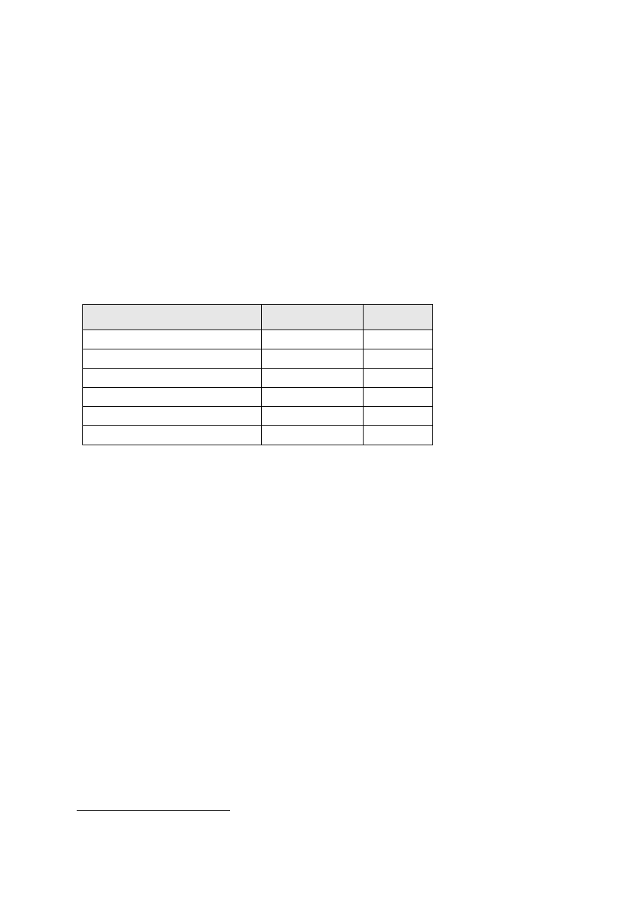
Table 5-1
– Non-insulated Sheathed Cable Lengths Required to Achieve 10Ω
Typical Soil Type
Resistivity (
Ωm)
Length (m)
Loams, garden soils etc.
25 or less
8
Chalk
50 or less
15
Clay
100 or less
29
Marsh/Peat
200 or less
58
Sand/Gravel/Clay mix
300 or less
87
Slate/Shale/Rock
500 or less
115
If these conditions cannot be satisfied the service shall be converted to PME (provided the
installation complies with the BS 7671 bonding requirements), or a TT earthing system shall
be used.
5.3.3
Converting Existing Customers to PME
Customers with an existing separate neutral and earth, connected to an SNE cable network
can be converted to a combined neutral and earth (PME) supply provided the following
requirements are satisfied:
The customer's installation complies with BS 7671.
A new PME cut-out is installed.
There are no shared metallic services (water, gas etc) with other properties (e.g. flats in
the same building). If there are shared metallic services all properties shall be converted
to PME and the neutrals bonded together in accordance with the rules for multi-occupancy
buildings detailed in EDS 06-0017.
The SNE cable is replaced with a CNE cable (or the neutral and earth are combined at the
service joint and at the cut-out).
An earth electrode is required at the service joint. However a length of SNE cable in direct
contact with the ground will normally provide a suitable connection with earth and satisfy
this requirement.
Note: It is not permitted to simply bond the neutral and earth at the cut-out
3
.
Appendix C explains the implications of only bonding the neutral and earth at the cut-out.

LV Network Earthing Design
Document Number: EDS 06-0016
Version: 6.1
Date: 31/07/2015
© UK Power Networks 2018 All rights reserved
14 of 27
5.3.4
Looped Services
When alterations are made to any cable associated with a SNE cable looped
4
service
arrangement, with cable sheath earth terminals provided by UK Power Networks, the earthing
systems at the looped property and the house connected to the main
5
service shall remain the
same as each other. If one property is converted to PME, with the other retaining a SNE cable
sheath earth, there would be a risk of differences in potential between un-bonded metalwork
within the SNE earthed property in the event of an open circuit neutral fault on the main
service. Refer to EDS 08-2101 for further information.
4
A looped service is a service that is derived from a connection to another service cable, either by an underground
cable joint on or from the live-side cut-out terminals of the main service.
5
The main service is the service that connects directly to the mains cable and to which the loop service connects.

LV Network Earthing Design
Document Number: EDS 06-0016
Version: 6.1
Date: 31/07/2015
© UK Power Networks 2018 All rights reserved
15 of 27
5.4
Overhead Line Networks
New overhead line networks are constructed using aerial bundled conductors (ABC) and will
be suitable for PME.
Existing open-wire low voltage overhead line networks are also suitable for PME. If an
overhead line network is encountered that is not PME, it shall be converted to PME before
any other work proceeds.
Low voltage overhead line PME networks shall satisfy the following requirements:
The HV and LV earths on pole-mounted transformers shall be segregated as specified in
EDS 06-0015.
The supply neutral conductor shall be connected in such a way to minimise corrosion or
breakage risks. (Single line tap type connections for neutral line conductors, tier type cable
box neutrals or transformer neutral connections are not acceptable).
The supply neutral conductor shall be connected to an earth electrode or the supply neutral
conductor of another main at the final support of every main.
Additional earth electrodes shall be installed every six spans along the overhead line and
at the end of each section of overhead line.
The cable sheaths and metallic cable boxes on poles supporting cable terminations shall
be connected to the supply neutral conductor.
Any multi-service, group service position or under-eaves wiring supplying more than four
customers shall be fitted with an earth electrode. If the supplies are single-phase they
should be reconfigured to ensure phase balance across all three phases as much as
possible.
The following additional requirements shall be applied when open-wire overhead line networks
with continuous earth wires are replaced with ABC:
All sections of associated main and any other main likely to be used as an alternative
supply between the secondary substation and the customer shall be constructed to the
PME requirements outlined above.
Any service aerial earth wires shall be removed.
Customers utilising a SNE service shall be converted to PME (provided the installation
complies with the BS 7671 bonding requirements) or a TT earthing system shall be used.
However, existing customers beyond the ABC may retain a SNE service provided they are
connected to a continuous length of non-insulated metallic sheathed cable in direct contact
with the ground sufficient to limit the rise of potential under open-circuit neutral conditions.
These criteria will be satisfied if the length of metallic cable sheath in contact with the
ground is sufficient to give a resistance to earth of
10Ω or less. Table 5-1 specifies the
length required to achieve this in different soil conditions.
LV Network Earthing Design
Document Number: EDS 06-0016
Version: 6.1
Date: 31/07/2015
© UK Power Networks 2018 All rights reserved
16 of 27
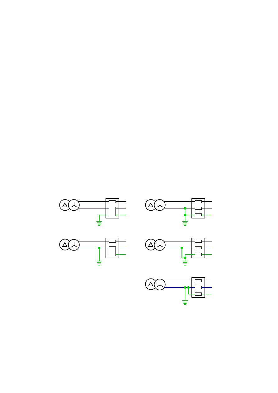
5.5
Protective Neutral Bonding (PNB)
Although PME is the preferred option protective neutral bonding (PNB) may provide a better
solution in circumstances where it is not practical to install the LV earth at the transformer. In
a PNB earthing system the LV neutral conductor is connected to an earth electrode at a point
remote from the transformer at or near the customer's supply terminals (refer to Appendix B
for further details).
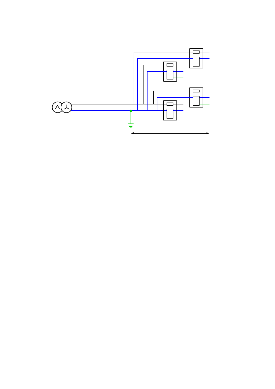
PNB may only be used if the following criteria are satisfied:
A maximum of four customers.
The connection to earth shall be made as close as possible to customer's supply terminals
and no more than 40m from the furthest customer.
The earth electrode shall have a maximum resistance of 20Ω.
The earth electrode shall be a minimum of 8m from any HV earth or HV metallic sheath
cable.
The metallic sheaths of any LV cables shall also be connected to the earth electrode.
The transformer tank and associated HV metalwork shall be connected to the HV earth
electrode.
A PNB earth terminal shall be treated as a PME earth terminal and the appropriate labelling
applied (Refer to EDS 06-0017).
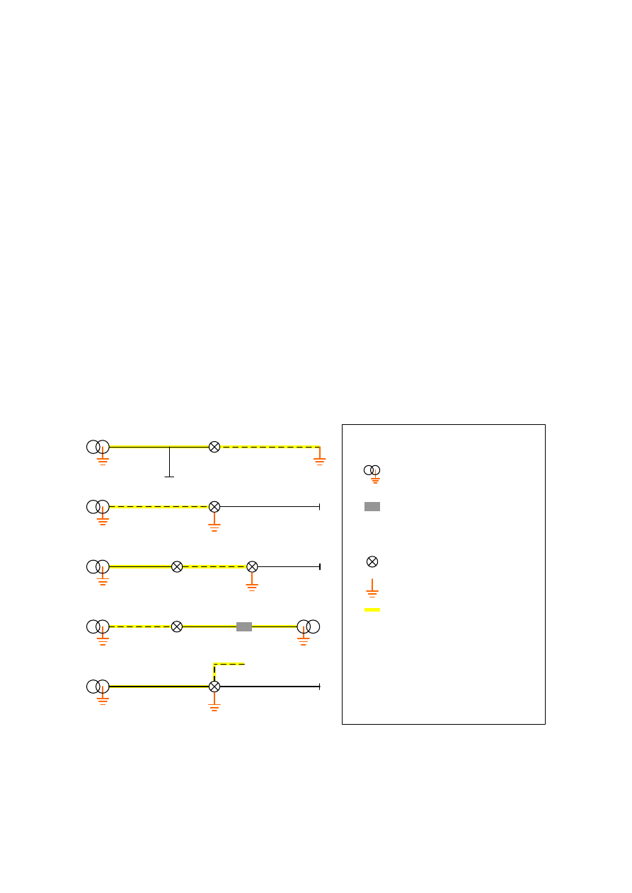
Various PNB arrangements are illustrated in Figure 5-3 and Figure 5-4.
HV : LV
HV : LV
HV : LV
HV : LV
HV : LV
SNE Cut-out
CNE Cut-out
SNE Cut-out
SNE Cut-out
CNE Cut-out
Figure 5-3
– PNB Options using CNE and SNE Cut-outs
LV Network Earthing Design
Document Number: EDS 06-0016
Version: 6.1
Date: 31/07/2015
© UK Power Networks 2018 All rights reserved
17 of 27
HV : LV
<40m
CNE Cut-out
CNE Cut-out
CNE Cut-out
CNE Cut-out
Figure 5-4
– PNB for up to Four Customers
5.6
Load Balance
The voltage which appears on the supply neutral conductor (and consequently on customers’
exposed metalwork) beyond a broken neutral position is influenced by the load balance on the
main. If the load is uniformly distributed across the phases along the main, the neutral voltage
rise is theoretically zero beyond a neutral break and will be low in practice. Maintaining good
load balance will therefore minimise neutral voltage rise and consequent risk of shock under
broken neutral conditions. Good load balance will also minimise neutral voltage rise under
normal operating conditions, reduce losses, and maximise the load capacity available from
the assets concerned. It is the best way to reduce risks associated with broken neutrals and
is an extremely important factor in network operation and design.
Therefore designs for new networks and alterations to existing networks shall clearly indicate
the phase to which customers shall be connected. Furthermore this shall be clearly
communicated to those making the service connections.
When legacy single-phase or two-phase SNE cable networks are replaced with modern three-
phase CNE cable, particular care should be taken to balance load. Wherever possible, cable
sheaths and neutrals at the ends of SNE cables should be bonded and interconnected.
5.7
Earth Fault Loop Impedance
For guidance on earth fault loop impedance refer to EDS 08-2000 (new network design) or
EDS 06-0004 (existing networks).
LV Network Earthing Design
Document Number: EDS 06-0016
Version: 6.1
Date: 31/07/2015
© UK Power Networks 2018 All rights reserved
18 of 27
6
LV Earthing Requirements
6.1
Earth Electrodes
The permitted earth electrodes are given in Table 6-1. Refer to Error! Reference source not
found. for a complete range of electrode sizes for different values of soil resistivity.
Note: The use of rod electrodes is preferred but due to practical difficulties, particularly in
urban areas where damage can be caused to other services, cable electrodes are acceptable.
Table 6-1
– Earth Electrodes
Cable Size
Underground Cable Network
Overhead Network
Up to
35mm
2
1.2m earth rod connected via 35mm
2
covered copper cable or 2m of 35mm
2
bare copper cable laid directly in trench
underneath the LV cable
1.2m earth rod connected via 35mm
2
covered copper cable (below ground)
and 95mm
2
covered aluminium cable
(above ground)
> 35mm
2
1.2m earth rod connected via 70mm
2
covered copper cable or 2m of 70mm
2
bare copper cable laid directly in trench
underneath the LV cable
1.2m earth rod connected via 70mm
2
covered copper cable (below ground)
and 95mm
2
covered aluminium cable
(above ground)
6.2
Bonding Connections
The minimum size of earthing and bonding connections are given in Table 6-2. Below ground,
i.e. buried, earthing and bonding conductors shall be copper. Above ground bonding
conductors may be copper, aluminium or corrosion protected steel of the appropriate cross
sectional area.
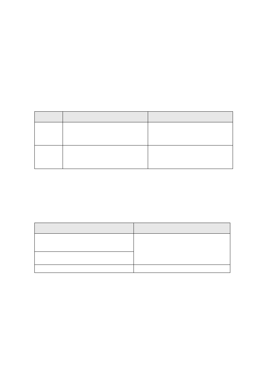
Table 6-2
– Bonding Connections
Connection Type
Copper or Copper Equivalent
Main LV earth at secondary substation i.e.
connection between transformer neutral (star-
point) and earth
Refer to EDS 06-0014 for the requirements
Between neutral busbar and earth busbar at
secondary substation
LV earth at pole-mounted sites
Refer to EDS 06-0015 for the requirements
LV Network Earthing Design
Document Number: EDS 06-0016
Version: 6.1
Date: 31/07/2015
© UK Power Networks 2018 All rights reserved
19 of 27
Connection Type
Copper or Copper Equivalent
Between supply neutral conductor and PME
earth electrode
For cable sizes up to 35mm
2
: 50mm
2
PVC
covered aluminium cable or 35mm
2
PVC
covered copper cable
For cable sizes greater than 35mm
2
: 95mm
2
PVC covered aluminium cable or 70mm
2
PVC
covered copper cable
Between supply neutral conductor and link box
or feeder pillar steelwork
Between sheath of SNE cable and neutral of
CNE cable
At customer’s premises between service
neutral and main earthing terminal
16mm
2
or half the size of the neutral meter
tail, whichever is the larger.
Note: This is usually built into the cut-out
At customer’s premises between the main
earthing terminal and the earth bar of the
consumer unit
Note: The bonding between the main earthing
terminal and the consumer unit is the
responsibility of the consumer. It is given here
for information only.
16mm
2
or half the size of the neutral meter
tail, whichever is the larger
6.3
Earth Resistance Values
The resistance of the supply neutral conductor to the general mass of earth shall not at any
point exceed 20
Ω. To achieve this value the earth electrode resistance values given in Table
6-3 shall be used.
Table 6-3
– Earth Electrode Resistance Values.
Electrode
Resistance Value
Main LV Earth
20
Ω
Additional PME Earth
100Ω

LV Network Earthing Design
Document Number: EDS 06-0016
Version: 6.1
Date: 31/07/2015
© UK Power Networks 2018 All rights reserved
20 of 27
7
References
EDS 06-0001
Earthing Standard
EDS 06-0004
Earth Fault Loop Impedance Requirements (internal document only)
EDS 08-2101
LV Customer Supplies up to 100A Single Phase
EDS 08-2102
LV Customer Unmetered Supplies
EDS 08-2000
LV Network Design
EDS 06-0014
Secondary Substation Earthing Design
EDS 06-0015
Pole-mounted Equipment Earthing Design
EDS 06-0017
Customer LV Installation Earthing Design
EDS 06-0018
NetMap Earthing Information System (internal document only)
EDS 08-0136
LV Network Design
ENA ER G12/4
Requirements for the Application of Protective Multiple Earthing to Low
Voltage Networks
IEC 60364
Electrical Installations for Buildings
The Electricity Safety, Quality and Continuity Regulations (ESQC) 2002 as amended (2006)
BS 7671:2008 incorporating Amendment No 3: 2015
– Requirements for Electrical
Installations (IET Wiring Regulations Seventeenth Edition)

LV Network Earthing Design
Document Number: EDS 06-0016
Version: 6.1
Date: 31/07/2015
© UK Power Networks 2018 All rights reserved
21 of 27
Appendix A
– ESQC Regulations
The Electricity Safety, Quality and Continuity Regulations 2002 contain a number of clauses
covering earthing. A summary of these is given below:
Continuity of the Supply Neutral Conductor and Earthing Connections
Regulation 7(1) A generator or distributor shall, in the design, construction, maintenance or
operation of his network, take all reasonable precautions to ensure continuity of the supply
neutral conductor.
Regulation 7(2) No generator or distributor shall introduce or retain any protective device in
any supply neutral conductor or any earthing connection of a low voltage network which he
owns or operates.
General Requirements for Connection with Earth
Regulation 8(1) A generator or distributor shall ensure that, so far as is reasonably practicable,
his network does not become disconnected from earth in the event of any foreseeable current
due to a fault.
Regulation 8(3) A generator or distributor shall, in respect of any low voltage network which
he owns or operates ensure that:
a) the outer conductor of any electric line consisting of concentric conductors shall be
connected with earth.
b) every supply neutral conductor is connected with earth at, or as near as is practical, to the
source of voltage, except that where there is only one point in a network at which
consumers’ installations are connected to a single source of voltage, that connection may
be made at that point, or at another point nearer to the source of voltage.
c) no impedance shall be inserted in any connection with earth of a low voltage network other
than that required for the operation of switching devices or instruments, or equipment for
control, telemetry or metering.
Regulation 8(5) A consumer shall not combine the neutral and protective functions in a single
conductor in his installation.
Regulation 8(5)
Paragraphs (1) to (4) shall not apply to a generator’s network which is situated
within a generating station if, and only if, adequate alternative arrangements are in place to
prevent danger.
Protective Multiple Earthing
Regulation 9(1)
This regulation applies to distributors’ low voltage networks in which the
neutral and protective functions are combined.
Regulation 9(2) In addition to the neutral with earth connection required under regulation
8(4)(b), a distributor shall ensure that the supply neutral conductor is connected with earth at:
a) a point no closer to the source of voltage (as measured along the distributing main) than
the junction between the distributing main and the service line (the supply neutral
conductor of the latter being connected to the protective conductor of a consumer’s
installation) which is most remote from the source.
b) such other points as may be necessary to prevent, so far as is reasonably practicable, the
risk of danger arising from an accidental disconnection of any such connection with earth.

LV Network Earthing Design
Document Number: EDS 06-0016
Version: 6.1
Date: 31/07/2015
© UK Power Networks 2018 All rights reserved
22 of 27
Regulation 9(3) Paragraph (2)(a) shall only apply where the supply neutral conductor of the
service line referred to in paragraph (2)(a) is connected to the protective conductor of a
consumer's installation.
Regulation 9(4) The distributor shall not connect his combined neutral and protective
conductor to any metalwork in a caravan or boat.
Equipment on a Consumer's Premises
Regulation 24 (1) A distributor or meter operator shall ensure that each item of his equipment
which is on a consumer's premises, but which is not under the control of the consumer
(whether forming part of the consumer's installation or not), is:
a) suitable for its purpose.
b) installed and, so far as is reasonably practicable, maintained so as to prevent danger.
c) protected by a suitable fusible cut-out or circuit-breaker which is situated as close as is
reasonably practicable to the supply terminals.
Regulation 24(2) Every circuit breaker or cut-out fuse forming part of the fusible cut-out
mentioned in paragraph (1)(c) shall be enclosed in a locked or sealed container as
appropriate.
Regulation 24(3) Where they form part of his equipment, which is on a consumer's premises
but which is not under the control of the consumer, a distributor or meter operator (as
appropriate) shall mark permanently, so as clearly to identify the polarity of each of them, the
separate conductors of low voltage electric lines which are connected to supply terminals, and
such markings shall be made at a point which is as close as is practicable to the supply
terminals in question.
Regulation 24(4) Unless he can reasonably conclude that it is inappropriate for reasons of
safety, a distributor shall, when providing a new connection at low voltage, make available his
supply neutral conductor or, if appropriate, the protective conductor of his network for
connection to the protective conductor of the consumer's installation.
Regulation 24(5) In this regulation the expression "new connection" means the first electric
line, or the replacement of an existing electric line, to one or more consumer's installations.
Earthing of Metalwork
Regulation 10(1) Subject to paragraph (2), and without prejudice to any other requirement as
to earthing, a generator, distributor or meter operator, as the case may be, shall ensure that
any metalwork enclosing, supporting or otherwise associated with his equipment in a network
and which is not intended to serve as a phase conductor is, where necessary to prevent
danger, connected with earth.
Regulation 10(2) Paragraph (1) shall not apply:
a) to any metalwork attached to, or forming part of, a wooden pole support, the design and
construction of which is such as to prevent, so far as is reasonably practicable, danger
within 3m of the ground from any failure of insulation or failure of insulators.
b) to any wall-mounted metal bracket carrying an overhead line not connected with earth,
where the line is both supported by an insulator and the part of the line in contact with the
insulator is itself surrounded by insulation.

LV Network Earthing Design
Document Number: EDS 06-0016
Version: 6.1
Date: 31/07/2015
© UK Power Networks 2018 All rights reserved
23 of 27
Appendix B
– Earthing Systems
B.1
IEC Standard for the Naming of Earthing Systems
Mains electricity systems are categorised in IEC 60364 according to how the earthing is
implemented. The common ones are TN-C-S, TN-S and TT
. In these descriptions, ‘system’
refers to both the supply and the installation, and ‘live parts’ includes the neutral conductor.
These conventions are used in BS 7671.
First letter (refers to supply networks):
T – The live parts in the system have one or more direct connects to earth (i.e. via the
neutral).
I – The live parts in the system have no connection to earth or are connected only through
a high impedance.
Second Letter (refers to the customer's installation):
T – All exposed conductive parts are connected via earth conductors to a local earth
connection.
N – All exposed conductive parts are connected to the earth provided by the supply
network.
Remaining Letters:
C – Combined neutral and earth functions (same conductor).
S – Separate neutral and protective earth functions (separate conductors).
Note: The letters are derived from the French language: T
– Terre (earth), N – Neutre (neutral),
S
– Séparé (separate), C – Combiné (combined) and I – Isolé (isolated).
B.2
BS 7671 Definitions
TN (Terre-Neutral)
A system having one or more points of the source of energy directly earthed, the exposed
conductive-parts of the installation being connected to that point by protective conductors. TN
systems may be subdivided as described below.
TN-C (Terre-Neutral-Combined)
A system in which neutral and protective functions are combined in a single conductor
throughout the system.
TN-S (Terre-Neutral Separated)
A system having separate neutral and protective conductors throughout the system.
TN-C-S (Terre-Neutral-Combined-Separated)
A system in which neutral and protective functions are combined in a single conductor in part
of the system.
TT (Terre-Terre)
A system having one point of the source of energy directly earthed, the exposed-conductive
parts of the installation being connected to earth electrodes electrically independent of the
earth electrodes of the source.
LV Network Earthing Design
Document Number: EDS 06-0016
Version: 6.1
Date: 31/07/2015
© UK Power Networks 2018 All rights reserved
24 of 27
B.3
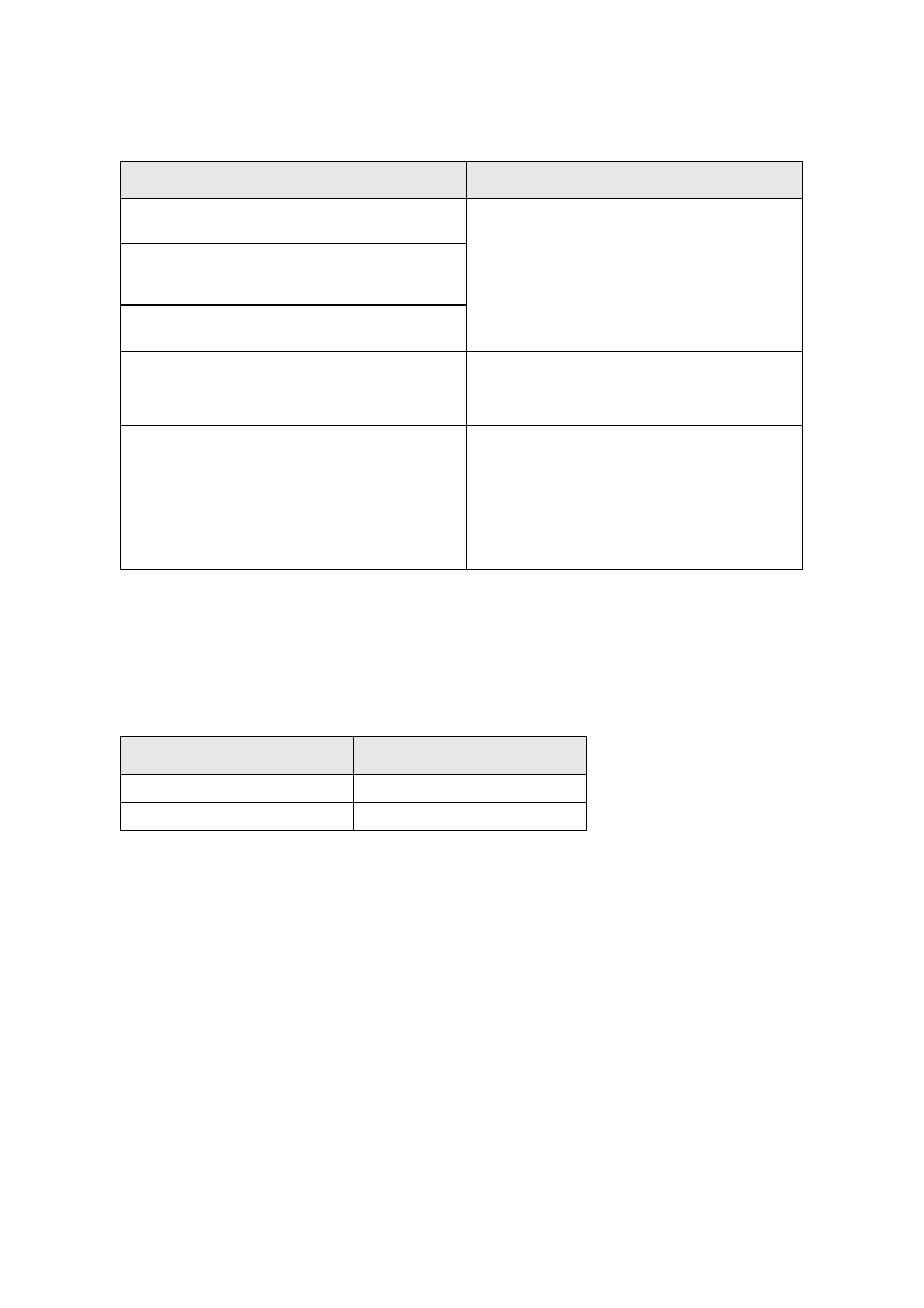
TN-S (Terre-Neutral Separated)
In a TN-S earthing system (refer to Figure B-1), the incoming supply has a single point of
connection between the supply neutral and earth at the supply transformer. The supply cables
have separate neutral and protective earth conductors (SNE) for the complete system, and
there is no bonding between the neutral and earth conductors, except at the supply
transformer. The neutral conductor may be a fourth core, or a split concentric cable may be
used with part of the concentric conductor insulated and used as the neutral. The sheath or a
separate conductor is used to provide the protective earth. The customer is provided with an
earth terminal connected to the sheath of the service cable or to the separate earth conductor.
Note:
TN-S was the default earthing system pre-1978 before PME became commonplace.
Since all extensions and repairs use CNE cable it shall be assumed that all networks will
have the neutral and protective earth conductors combined for at least part of the system;
they will therefore be TN-C-S. The only exceptions will be dedicated supplies to single
customers using a separate earth conductor.
Figure B-1
– TN-S Earthing System
B.4
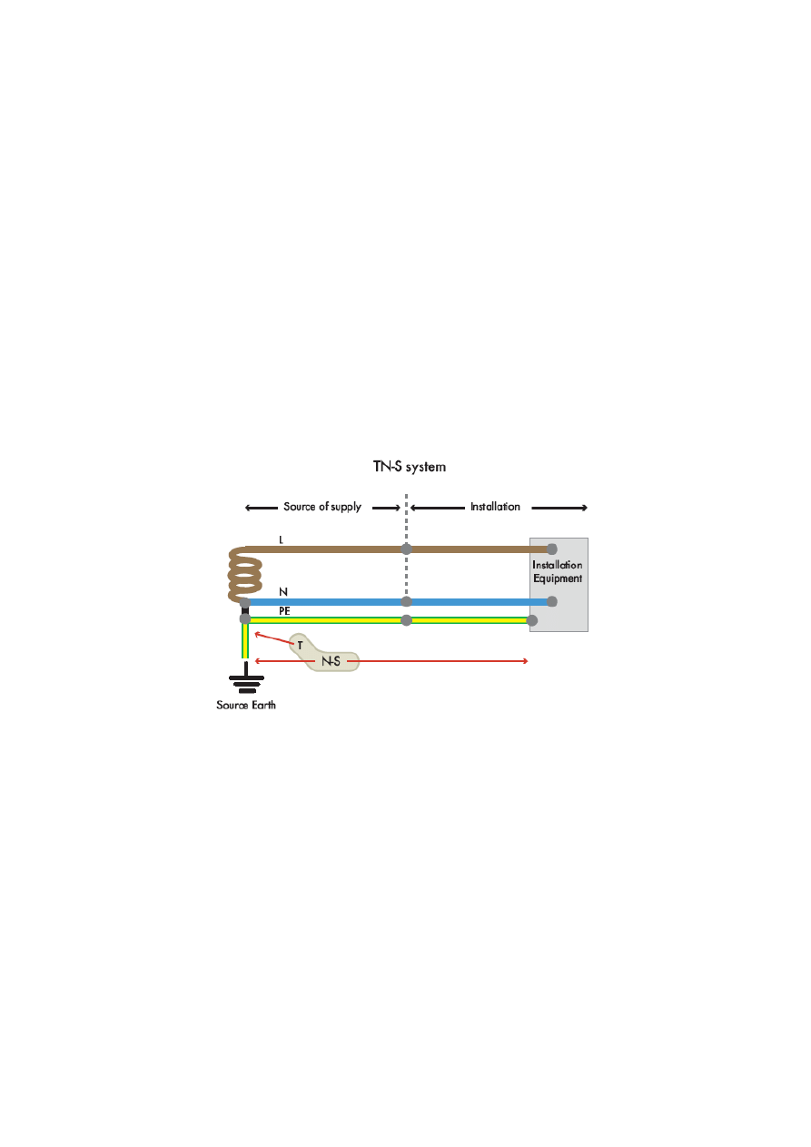
TN-C-S (Terre-Neutral-Combined-Separated)
The TN-C-S earthing system is a combination of TN-C and TN-S earthing systems. The supply
cables have a combined neutral and earth (CNE) metallic outer sheath with a PVC covering
(TN-C). The supply neutral conductor also serves as the protective earth and an earth terminal
is provided from it. The supply on the customers side is TN-S, i.e. the neutral and earth are
separate and only linked at the service termination. Both PME and PNB are examples of the
TN-C-S earthing system.
Note: If any part of a network has CNE cable, or has SNE cable with the sheath and neutral
bonded at any point other than at the transformer neutral terminal, the complete system is
classified as TN-C-S.
PME is a variant of the TN-C-S earthing system but additional earth electrodes are connected
to the neutral (Figure B-2).
LV Network Earthing Design
Document Number: EDS 06-0016
Version: 6.1
Date: 31/07/2015
© UK Power Networks 2018 All rights reserved
25 of 27
(PME)
Figure B-2
– PME Earthing System
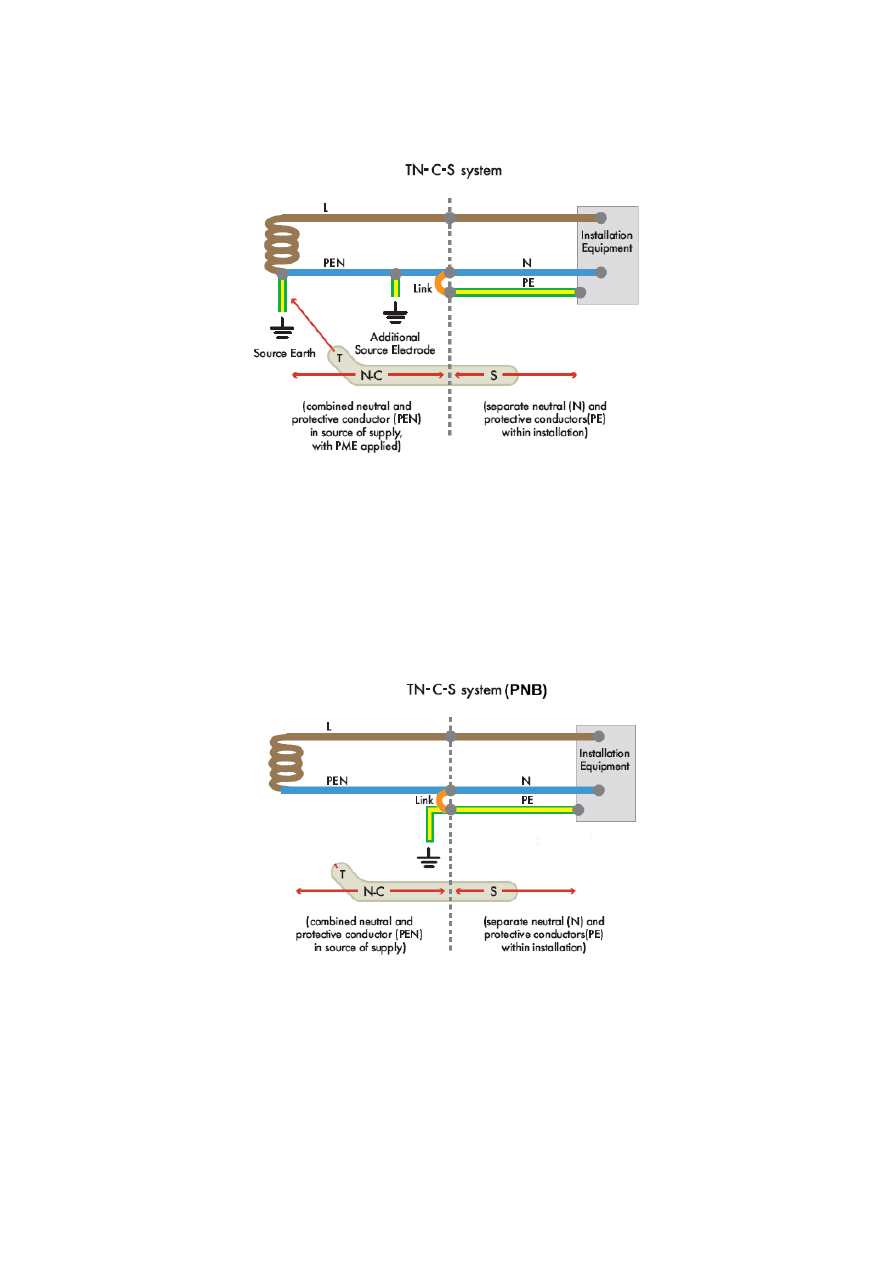
PNB is another variant of the TN-C-S earthing system and is similar to PME. PNB is generally
only used for supplies to a single customer or a small group of customers, e.g. a customer
supplied from a pole-mounted transformer. The neutral conductor is only earthed at one point
and therefore the transformer and the customer share a common neutral earth. The earth is
located closer to the customer than the transformer and often connected at cut-out. The
customer’s electrical installation requirements are exactly the same as for PME. Refer to
Figure B-3.
Figure B-3
– PNB Earthing System
LV Network Earthing Design
Document Number: EDS 06-0016
Version: 6.1
Date: 31/07/2015
© UK Power Networks 2018 All rights reserved
26 of 27
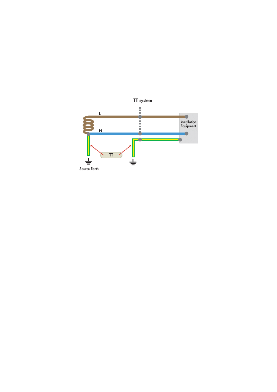
B.5
TT (Terre-Terre)
In a TT earthing system (Figure B-4), the supply is earthed at one or more points and the
supply cable sheaths are connected to it. The customer has an independent earth electrode
to which any exposed metalwork of the customer’s installation is connected. The earth loop
impedance is relatively high for this arrangement and therefore a residual current device
(RCD) is usually required to protect the customer's installation.
Customer's Earth
R
A
Figure B-4
– TT Earthing System
Note:
The resistance of this electrode shall be low enough to ensure that under fault conditions
the voltage on exposed metalwork will not exceed 50V.
BS 7671:2008 411.5.3 (ii) states that
50
n
A
I
R
V where
A
R
is the customer’s electrode
resistance and
n
I
is the rated residual operating current of the residual current device
(RCD). BS 7671:2008 also suggests that
A
R
should not exceed 200
Ω otherwise it may
not be stable.
BS 7671:2008 generally requires the use of an RCD for domestic properties, including
installations which utilise a distributor’s earth terminal; these systems are not TT systems.
LV Network Earthing Design
Document Number: EDS 06-0016
Version: 6.1
Date: 31/07/2015
© UK Power Networks 2018 All rights reserved
27 of 27
Appendix C
– Broken Neutral
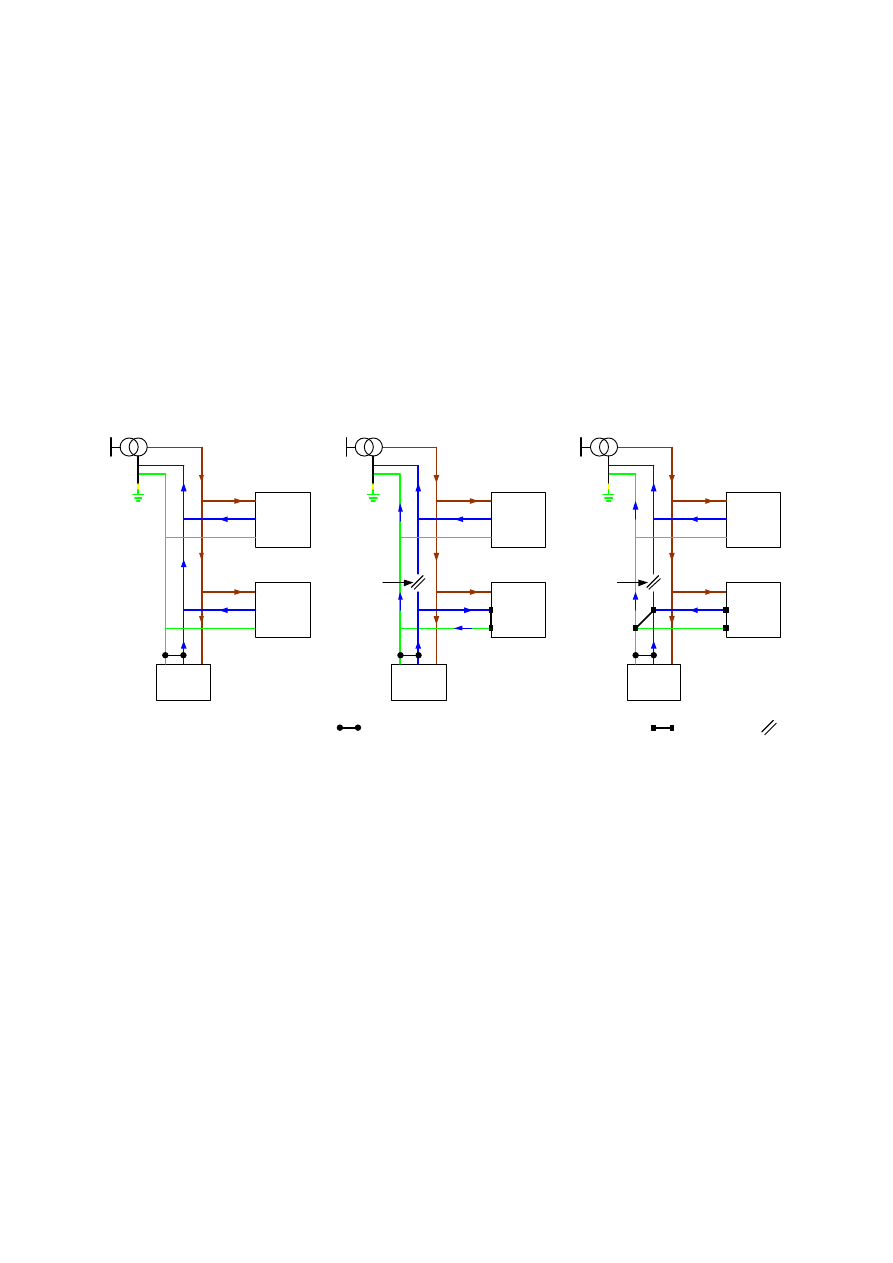
Figure C-5 (a) shows the current flow under normal conditions.
Figure C-5 (b) and (c) show the current flow under broken neutral conditions with a neutral-
earth bond at the cut-out only (b) and at both the cut-out and service joint (c). This
demonstrates that there is likely to be significant current flow through the service cable and
cut-out during a broken neutral fault if the neutral and earth are only bonded at the cut-out;
this could lead to overheating and damage to the service cable or the cut-out and possible
fire.
Therefore when converting existing customers to PME it is important that the requirements
detailed in Section 5.3.3 are satisfied.
Property
1
(SNE)
Live
Neutral
Network
Load
Property
2
(SNE)
Property
1
(SNE)
Live
Neutral
Network
Load
Property
2
(PME)
Broken Neutral
Property
1
(SNE)
Live
Neutral
Network
Load
Property
2
(PME)
Broken
Neutral
Network neutral earth bonds for PME conversion
(a)
(b)
(c)
Broken
Neutral
Network neutral earth bonds for customer converted to PME
Figure C-5
– Current Flow in a Network Converted to PME due to a Broken Neutral
Wyszukiwarka
Podobne podstrony:
EDS 06 0017 Customer LV Installation Earthing Design
EDS 06 0013 Grid and Primary Substation Earthing Design
EDS 06 0001 Earthing Standard
UKPN Customer Installation Earthing Design UPDATED (3)
Lab04 Network Design
Cisco Designing Network Security
I KZP 0016 06
Warhammer 40K 8th Edition FAQ Designers Commentary (2017 06 17)
Forex24 lv Copy Trading The Ultimate Guide Into Social Investment Networks
C07 design 06 AZ
C07 design 06 AZ
Design Guide 06 LRFD of W Shapes Encased in Concrete
PORTFOLIO DESIGN AND OPTIMIZATION USING NEURAL NETWORK BASED MULTIAGENT SYSTEM OF INVESTING AGENTS
MT st w 06
Kosci, kregoslup 28[1][1][1] 10 06 dla studentow
06 Kwestia potencjalności Aid 6191 ppt
więcej podobnych podstron