Motorola GmbH, CSS Center, Mobile Devices
Doc. No:
TSG_W220
Version: 1.0
Date: 19.12.2006
Title: Troubleshooting-Guide
W220
Page:
1 / 11
Repair Support Information
Writing by: Juan Ortiz
© Copyright 2003-2007 Motorola Inc. All Rights reserved.
Motorola internal use
DEBUG GUIDE W220 LEVEL 3
Motorola GmbH, CSS Center, Mobile Devices
Doc. No:
TSG_W220
Version: 1.0
Date: 19.12.2006
Title: Troubleshooting-Guide
W220
Page:
2 / 11
Repair Support Information
Writing by: Juan Ortiz
© Copyright 2003-2007 Motorola Inc. All Rights reserved.
Motorola internal use
Modify Date By:
INDEX
Special sequence & Requirements
Pag. 3
Tools
Pag. 4
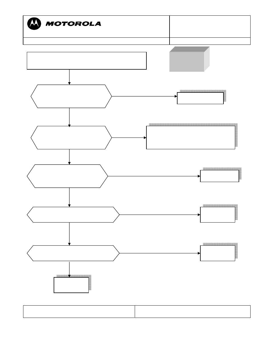
No power up
Pag. 5
High consume
Pag. 6 & 7
No TX
Pag. 8 &9
No RX
Pag. 10
Special Note
Pag. 11
Motorola GmbH, CSS Center, Mobile Devices
Doc. No:
TSG_W220
Version: 1.0
Date: 19.12.2006
Title: Troubleshooting-Guide
W220
Page:
3 / 11
Repair Support Information
Writing by: Juan Ortiz
© Copyright 2003-2007 Motorola Inc. All Rights reserved.
Motorola internal use
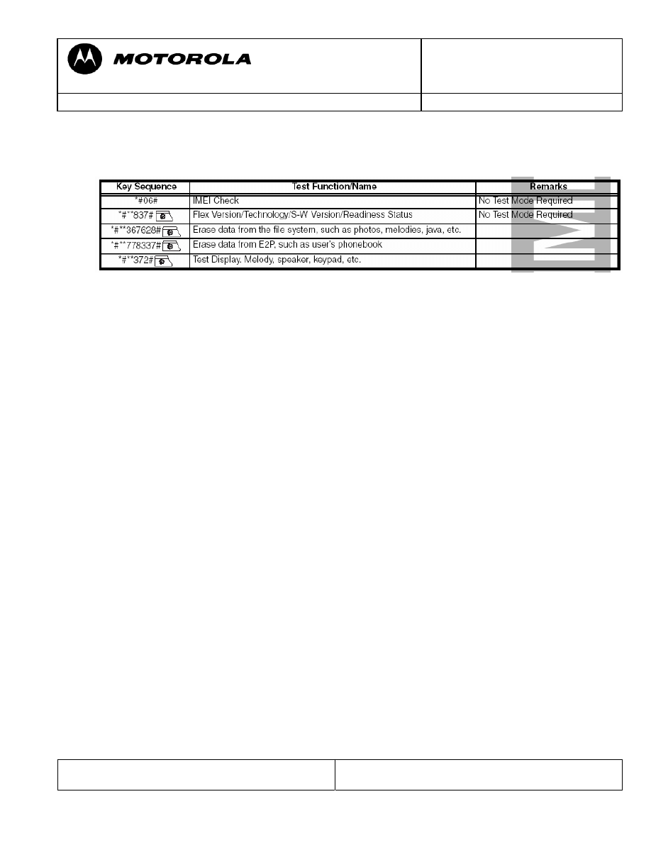
SPECIAL KEY SEQUENCE FOR SPECIAL FUNCTION
Requirements
- System Requirements
- Power supplies, Oscilloscope, Spectrum Analyzer, Test Set
- Pre-heater for lead free soldering/ solder machine for BGA´s
- Microscope
- Mobile Service Tools (MST)
- Field Service Bulletins
- Block diagrams/Schematics
- Basic information on troubleshooting Motorola Phones
- Make sure all contacts are clean
- Use newest approved Software
- RESET / MASTER CLEAR can fix some issues
- Do a visual inspection on customer abuse/liquid contamination
- Advice on working with lead free soldering
- Work very carefully because of underfill
- Use protection shields
- Use lead free flux
- Use pre heater (HAKKO 853)
Motorola GmbH, CSS Center, Mobile Devices
Doc. No:
TSG_W220
Version: 1.0
Date: 19.12.2006
Title: Troubleshooting-Guide
W220
Page:
4 / 11
Repair Support Information
Writing by: Juan Ortiz
© Copyright 2003-2007 Motorola Inc. All Rights reserved.
Motorola internal use
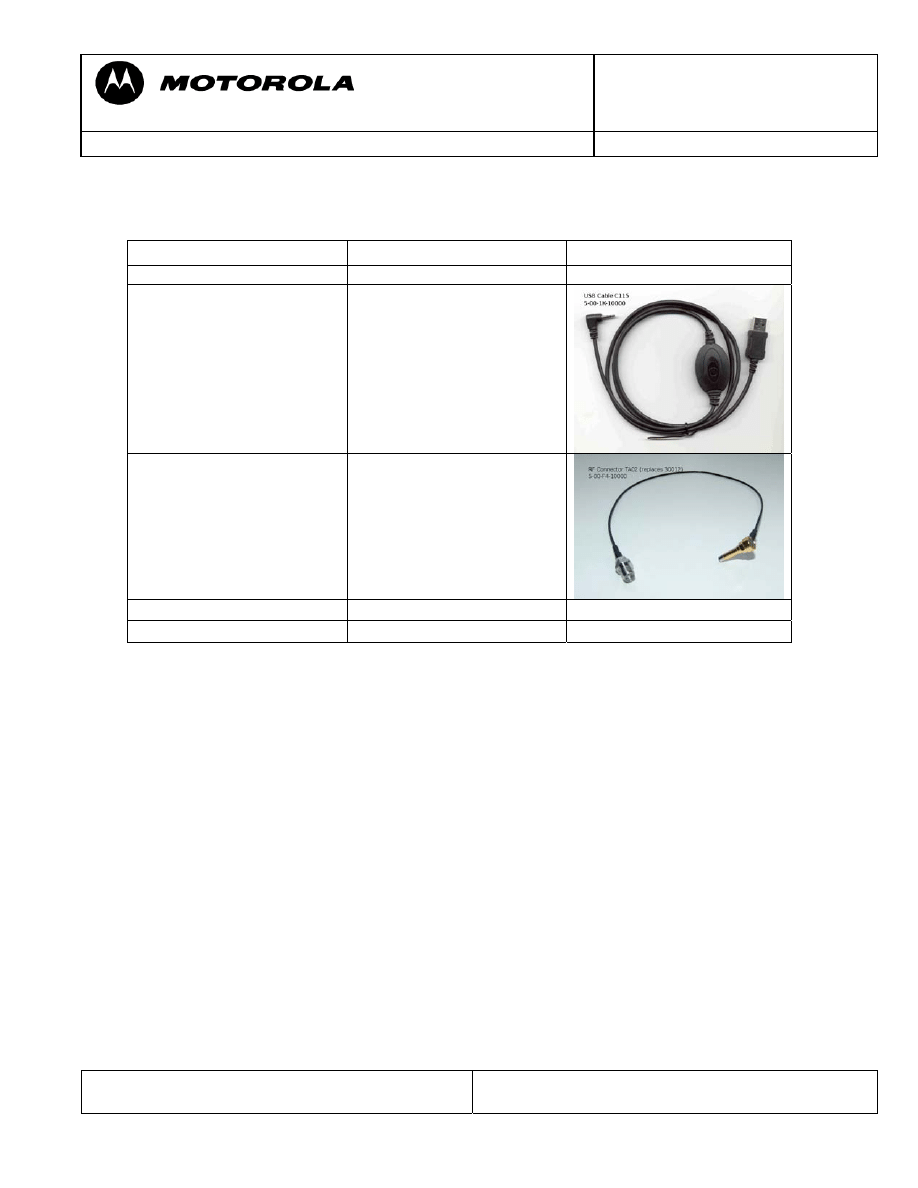
Tools Part-number Picture
USB cable C115, C116,
C117, C155, V170, V171
5-00-1K-10000
RF Probe TA02 (replaces
old revision 30012)
5-00-F4-10000
Main Battery W220/W300
5-00-X3-10000
Motorola GmbH, CSS Center, Mobile Devices
Doc. No:
TSG_W220
Version: 1.0
Date: 19.12.2006
Title: Troubleshooting-Guide
W220
Page:
5 / 11
Repair Support Information
Writing by: Juan Ortiz
© Copyright 2003-2007 Motorola Inc. All Rights reserved.
Motorola internal use
No
Yes
No
Yes
No
Yes
No
Yes
No
Yes
Connect the PCB to power supply with a external
power supply 4.2 v.
NO
POWER UP
The voltage in TP207 changes
from 4 V to 0 V when the
power button is pushed?
Are there information signal
in test point between U201
and U501?
Is there 26 MHz signal from U606?
Replace PCB
Replace
U606
Clean or replace keypad mylar, if the
failure persist replace U202, if the
failure still persist replace PCB
Is there 32,768 KHz signal from
X201?
Replace
X201
Is there current-consumption
when You try to power up the
PCB?
Replace U202
Replace
PCB
Motorola GmbH, CSS Center, Mobile Devices
Doc. No:
TSG_W220
Version: 1.0
Date: 19.12.2006
Title: Troubleshooting-Guide
W220
Page:
6 / 11
Repair Support Information
Writing by: Juan Ortiz
© Copyright 2003-2007 Motorola Inc. All Rights reserved.
Motorola internal use
In probably most cases these problems are caused by an off current. One first look should
be to verify whether there is an off current. If there is an off current it should be checked
whether the device draws current via battery and/or via external connector.
In case of an off current via battery there should be a low resistance (less than ~200
Ohm)/ or a short from BATT+_RAW (M5400-4) to GND.
To localize the defective part causing the short/ low resistance a simple way is to freeze
the board with a coolant spray, supply a battery voltage from a power supply using micro
clamp-type test probes, and see which parts are getting warm. This is a very basic and
essential method to troubleshoot off current / high current consumption failures.
The power supply should be set to 3.6V with current limitation to 2A. We strictly
recommend checking the current the PCB draws on the display of the power supply.
Shields covering suspected parts should be removed before freezing the PCB.
The PCB should be handled with care. After removing the shields the PCB should be
given some time to cool down slowly before freezing it to far below zero to avoid physical
stress to the multilayer PCB with lead free soldered parts.
In some cases the part, which is getting warm has itself an internal short. After removing
this part the off current should be fixed. For verification check off current or measure
resistance BATT+_RAW (M5400-4) to GND. A new part can be placed.
If the short / low resistance remains after removing the part which was getting warm, it
should be checked which signals/ voltages this parts provide. In the most cases this part
will provide a supply voltage to other parts from which one possibly could have an
internal short and therefore is getting warm.
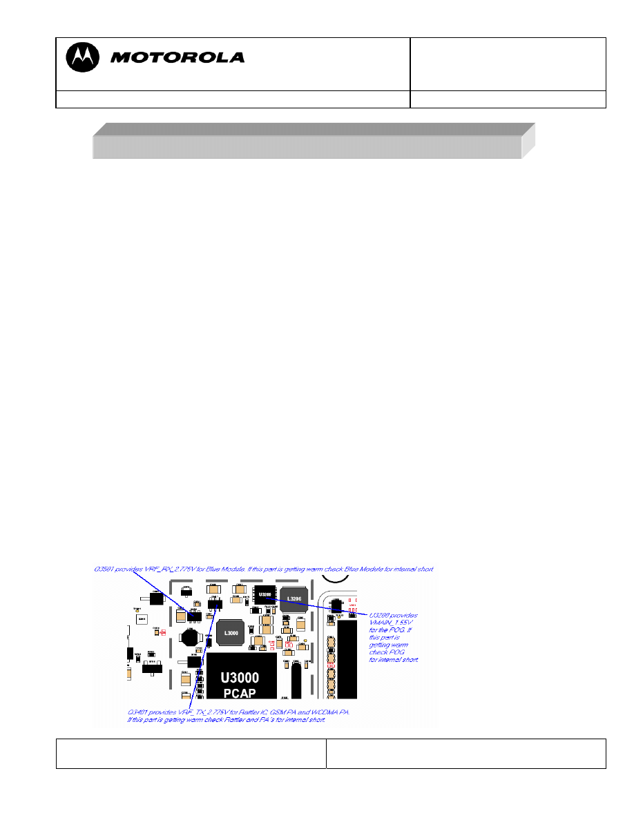
SPECIAL PROCEDURE FOR HIGH CURRENT FAILURE - EXAMPLE
Motorola GmbH, CSS Center, Mobile Devices
Doc. No:
TSG_W220
Version: 1.0
Date: 19.12.2006
Title: Troubleshooting-Guide
W220
Page:
7 / 11
Repair Support Information
Writing by: Juan Ortiz
© Copyright 2003-2007 Motorola Inc. All Rights reserved.
Motorola internal use
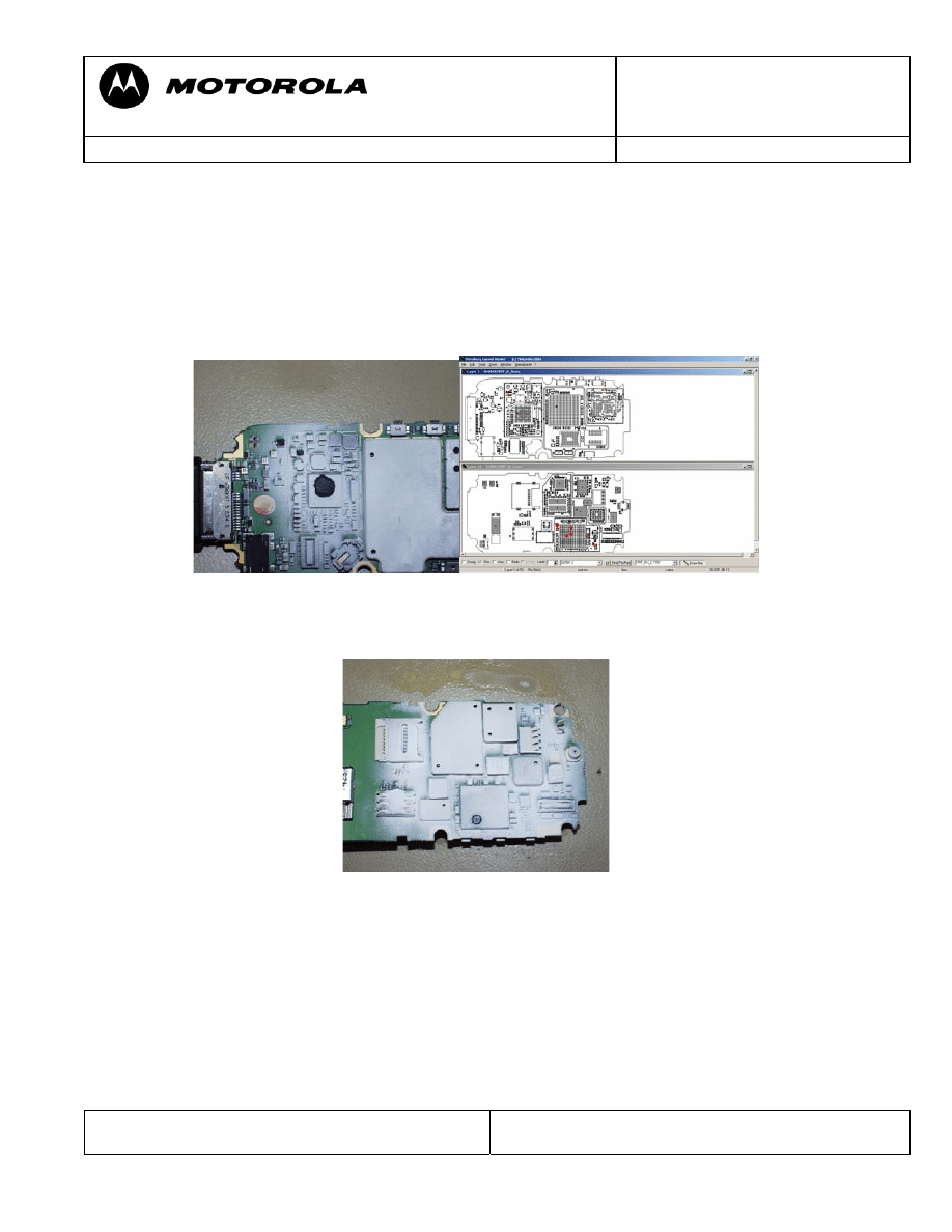
To find out the defective part an easy way is to use the Flensburg Layout Viewer to
follow the signal (check for Shorts Resistors after which the signals possibly could have a
changed name), and to remove the parts one after another, until the short is gone.
Most frequent parts with internal shorts causing these kinds of failures are the PA´s
Example:
- BAT00 – radio draws about 400 mA in standby, no off current
- Q3501/U3000 are getting warm
– Q3501 provides VRF_RX_2.775V for Blue Module U900 via Short Resistor
R902 (using Flensburg Layout Viewer )
- Blue Module U900 is also getting warm
Blue Module U900 itself has an internal short. Æ Defective U900
Motorola GmbH, CSS Center, Mobile Devices
Doc. No:
TSG_W220
Version: 1.0
Date: 19.12.2006
Title: Troubleshooting-Guide
W220
Page:
8 / 11
Repair Support Information
Writing by: Juan Ortiz
© Copyright 2003-2007 Motorola Inc. All Rights reserved.
Motorola internal use
No
Yes
Yes No
No
Yes
No
Yes
No
Yes
No
Yes
No
Yes
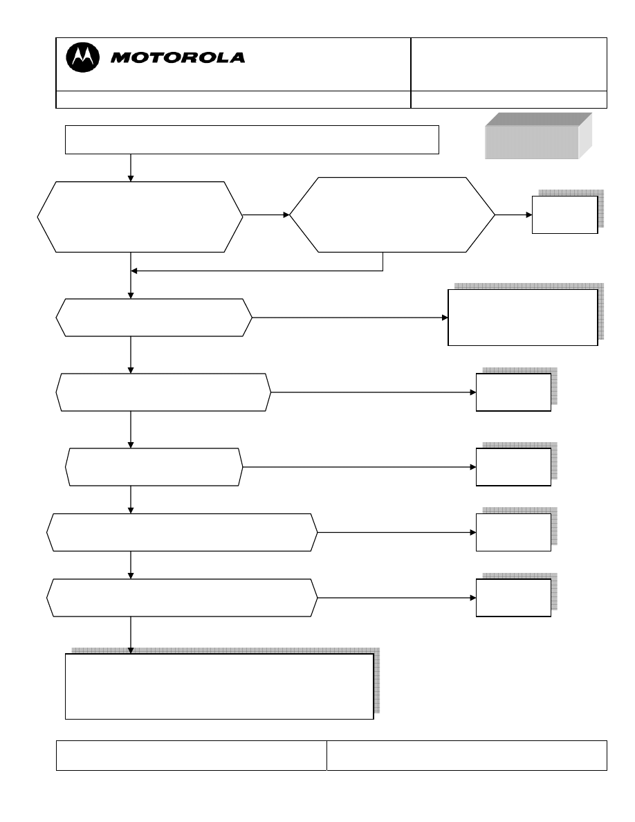
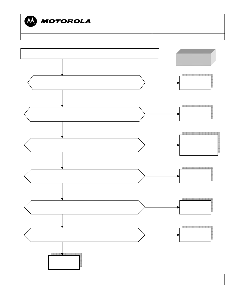
NO TX
Measure if at the output of
CON601 is signal and current-
consumtion of the in PCB is
200 mA?
Measure if at the input of
CON601 is a signal and
current-consumptionof the
PCB is 200 mA?
Replace
CON601
Is there a signal at C606 and
C605?
Check R601 and replace
it if is necessary if it is
OK replace U202
Replace
U605
Let radio transmit on GSM900 or DCS using MST program
Replace
U607
Is there a signal at C621 for DCS
and C613 for GSM?
Is there a signal in C630?
Checking and replacing if fail these components;
C605, C606, C611, C612, R602, R603, C613, C615,
L605, C621, C623, L604, C630, L611, C617, L608,
L612, C631 and R606 if the failure persist replace PCB
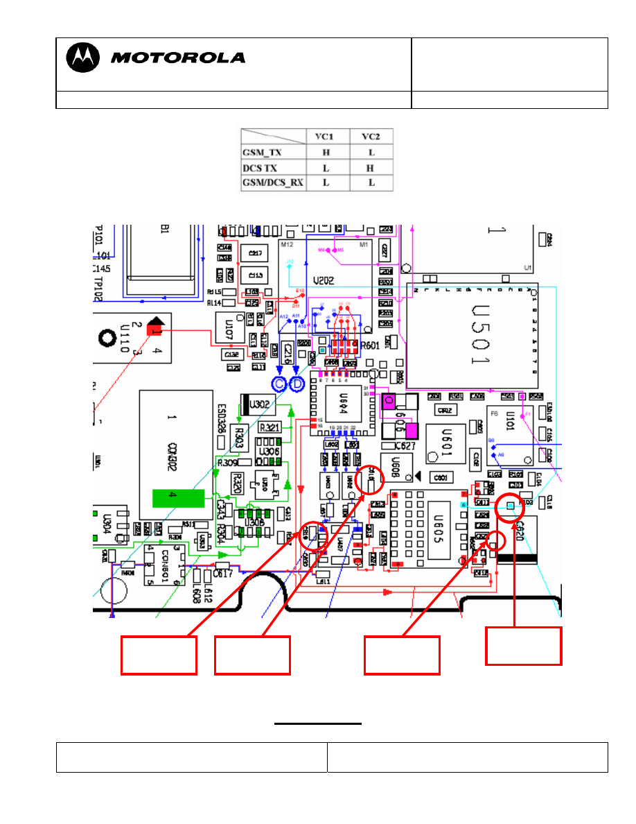
Is there a digital signal in PAON Test point?
(See figure 1)
Replace
U202
Is there a digital signal in APC Test point?
(See figure 1)
Replace
PCB
Motorola GmbH, CSS Center, Mobile Devices
Doc. No:
TSG_W220
Version: 1.0
Date: 19.12.2006
Title: Troubleshooting-Guide
W220
Page:
9 / 11
Repair Support Information
Writing by: Juan Ortiz
© Copyright 2003-2007 Motorola Inc. All Rights reserved.
Motorola internal use
Work table for duplexer
FIGURE 1
APC
Test Point
PAON
Test Point
C619
VC2
C618
VC1
Motorola GmbH, CSS Center, Mobile Devices
Doc. No:
TSG_W220
Version: 1.0
Date: 19.12.2006
Title: Troubleshooting-Guide
W220
Page:
10 / 11
Repair Support Information
Writing by: Juan Ortiz
© Copyright 2003-2007 Motorola Inc. All Rights reserved.
Motorola internal use
No
Yes
No
Yes
No
Yes
No
Yes
No
Yes
No
Yes
NO RX
Is there the same input signal as C605 for GSM and
C606 for DCS?
Replace
U202
Is there the same input signal as L601 for GSM and
L602 for DCS?
Is there the same input signal as L606 for GSM and
L607 for DCS?
Inject a RF from Test Set and put in RX the PCB using MST program
Replace
U604
Replace
U602 for GSM
U603 for GSM
Is there the same input signal as C630?
Replace
U607
Is there the same input signal as R606?
Replace
CON601
VC1 and VC2
are a low value? (See Figure 1)
Replace
U608
Replace
PCB
Motorola GmbH, CSS Center, Mobile Devices
Doc. No:
TSG_W220
Version: 1.0
Date: 19.12.2006
Title: Troubleshooting-Guide
W220
Page:
11 / 11
Repair Support Information
Writing by: Juan Ortiz
© Copyright 2003-2007 Motorola Inc. All Rights reserved.
Motorola internal use
SPECIAL NOTE
Follow up failures caused by repair action
Quite a lot of repairs which were sent to Level 4 service have a second fault, which is
caused by an unsuccessful repair trial.
We stricktly recommend visually checking the PCB for skewed or tombstoned parts,
soldering shorts or heating bubbles in PCB after every soldering action. Especially small
parts which are located close to shields can easily be misplaced during removal or setting
of the shields.
We experienced that some parts seems to be more heat sensitive than others.
Wyszukiwarka
Podobne podstrony:
Debug Guide s Triplets Version 1[1] 4
Debug Guide
SAT II Math Level 2 Study Guide
PERFORMANCE LEVEL, PL
guide camino aragones pl
Herbs for Sports Performance, Energy and Recovery Guide to Optimal Sports Nutrition
Meezan Banks Guide to Islamic Banking
NLP for Beginners An Idiot Proof Guide to Neuro Linguistic Programming
freespan spec guide
Eaton VP 33 76 Ball Guide Unit Drawing
Herbs to Relieve Headaches Keats Good Herb Guide
50 Common Birds An Illistrated Guide to 50 of the Most Common North American Birds
Configuration Guide WAN Access(V100R006C00 02)
installation guide
iR Shell 3 9 User Guide
1970 01 01 Kant039s 039perpetual peace039 utopia or political guide
M12 Oncore Users Guide Supplement
Body language is something we are aware of at a subliminal level
więcej podobnych podstron