
28-22
Digifant Ignition system,
component overview
Vehicles starting m.y. 1995
Notes:
Repair Manual , Fuel Injection & Ignition,
Repair Group 24
Only information specific to the ignition system
is covered in this Repair Group. For Fuel
injection system information:
The Fuel Injection and Ignition system Engine
Control Module is equipped with On Board
Diagnostic capability.
Components marked with an * are checked via
the On Board Diagnostic system.
Before performing repairs and/or
troubleshooting, check the Diagnostic Trouble
Code *(DTC) memory
Page 01-53
.
Safety precautions
Page 28-27
Checking and adjustment data, spark plugs

Page 28-28
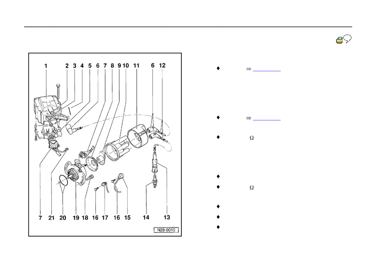
28-23
1 - Ignition coil -N152-
checking:
Page 28-36
2 - Terminal 4
3 - Terminal 15
4 - Terminal 1
5 - Ignition coil power output stage -N157-
checking:
Page 28-37
6 - RFI Suppressor
0.6 to 1.4 k
7 - Connector
8 - Dust cap
9 - Rotor
marking: R1
0.6 to 1.4 k
10 - Distributor cap
check for cracks and signs of arcing (carbon tracks)
check electrode wear
clean before fitting

check carbon brush for wear and freedom of
movement
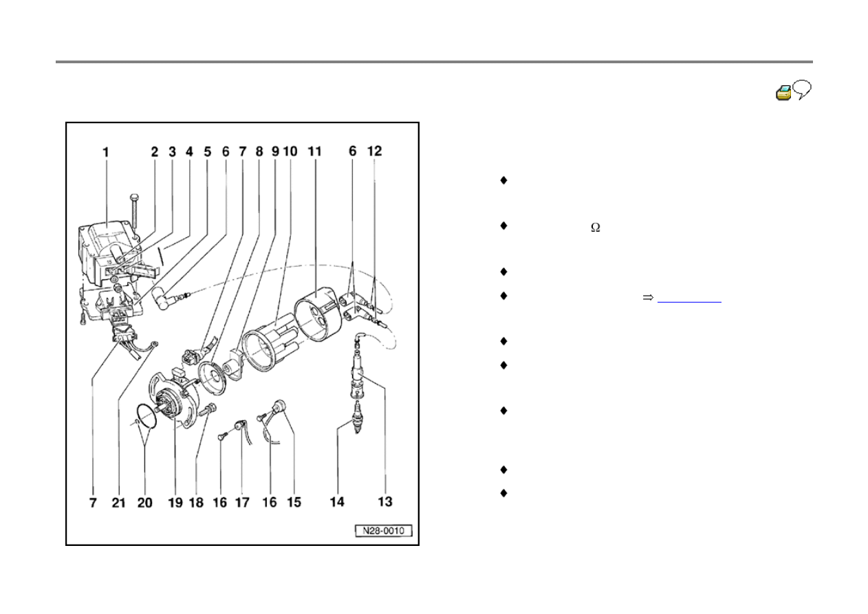
28-24
11 - RFI shield
12 - High tension cable
check for continuity
13 - Spark plug connector
4000 to 6000
14 - Spark plug
30 Nm (22 ft lb)
type and electrode gap
Page 28-28
15 - Knock sensor 2 -G66-**
on left in direction of travel
on engine block
16 - 20 Nm (15 ft lb)
tightening torque influences the function of the knock
sensor
17 - Knock sensor 1 -G61-*
on right in direction of travel
on engine block
18 - 10 Nm (7 ft lb)
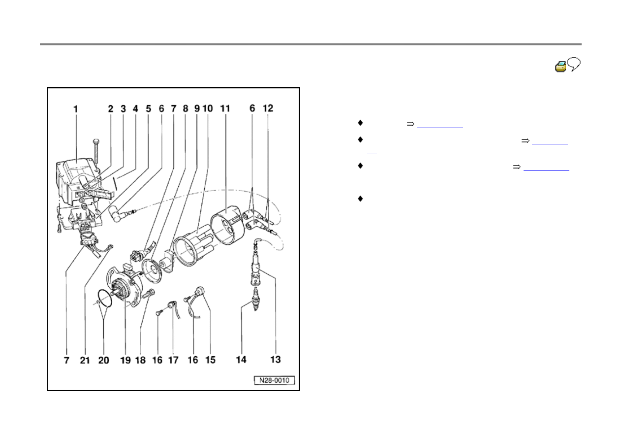
28-25
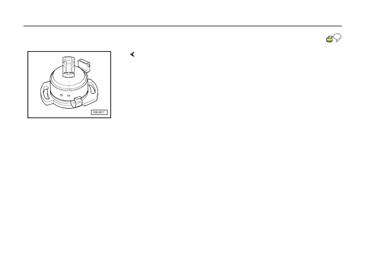
19 - lgnition Distributor with Camshaft Position sensor
G40
installing:
Page 28-29
ignition timing, checking and adjusting:
Page 28-
31
Camshaft Position sensor. checking:
Page 28-35
20 - O-ring
replace if damaged
21 - Ground strap
28-26
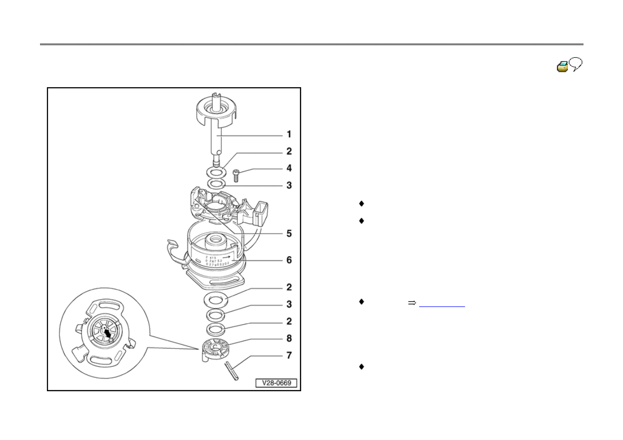
Ignition distributor, disassembling and
assembling
Note:
When assembling, ensure that coupling /item 8) can be
moved slightly on the pin (item 7) and distributor shaft (item
1) play is not restricted.
1 - Distributor shaft
with Camshaft Position sensor trigger wheel
pull out after removing spring pin (item 7)
2 - Shim(s)
3 - Plastic washer
4 - 3 Nm (127 in. Ib)
5 - Camshaft Position sensor -G40-
checking:
Page 28-35
6 - Distributor housing
7 - Spring pin
8 - Coupling
before removing, mark position of drive dog to shaft
(item 1)
28-27
Safety precautions
To prevent injuries to persons and/or damage to
the fuel injection and ignition system
components, observe the following points:
Do not touch or disconnect ignition wires when
the engine is running or cranking at starter
speed.
The ignition must be switched off when
disconnecting or connecting injection and
ignition system component wiring as well as
test instrument cables.
If the engine requires cranking at starter speeds
but without starting, e.g. when checking
compression: Disconnect the harness
connector from the Engine Speed sensor
(below bracket on left side of cylinder head).
Do not connect a capacitor (of any description)
to the ignition coil terminal 1 (-).
Do not replace the 1000
(identification: R1)
distributor rotor with a different type even for
Radio Frequency Interference (RFI)

suppression.
For RFI suppression purposes only, high
tension leads must have a resistance of 1000
and spark plug connectors must have a
resistance of 5000
.
28-28
Test data, spark plugs
Engine code
ACU
Ignition timing
1)
Checking value
3 to 8 before TDC
Adjusting value
6 1 before TDC
Engine speed
2000 to 2500 rpm
Ignition timing at 2200 rpm
4)
23 to 33 BTDC
Firing order
1-2-4-5-3
Spark plugs
Manufacturers gap: designation:
101 000 026 AA
3)
101 000 005 AE
101 000 001 AE
101 000 007 AB
N9 BMC
3)
0.6 mm max.
2)
W 8 DTC 0.7 to 0.9 mm
14-8 DTU 0.7 to 0.9 mm
N 7 BYC 0.7 to 0.9 mm
Tightening torque
25 Nm (18 ft lb)
l)
Checking and adjusting
Page 28-31
2)
Gap between the ground electrode and center electrode

3)
Especially recommended for short journeys
4)
Ignition timing point, checking
28-29
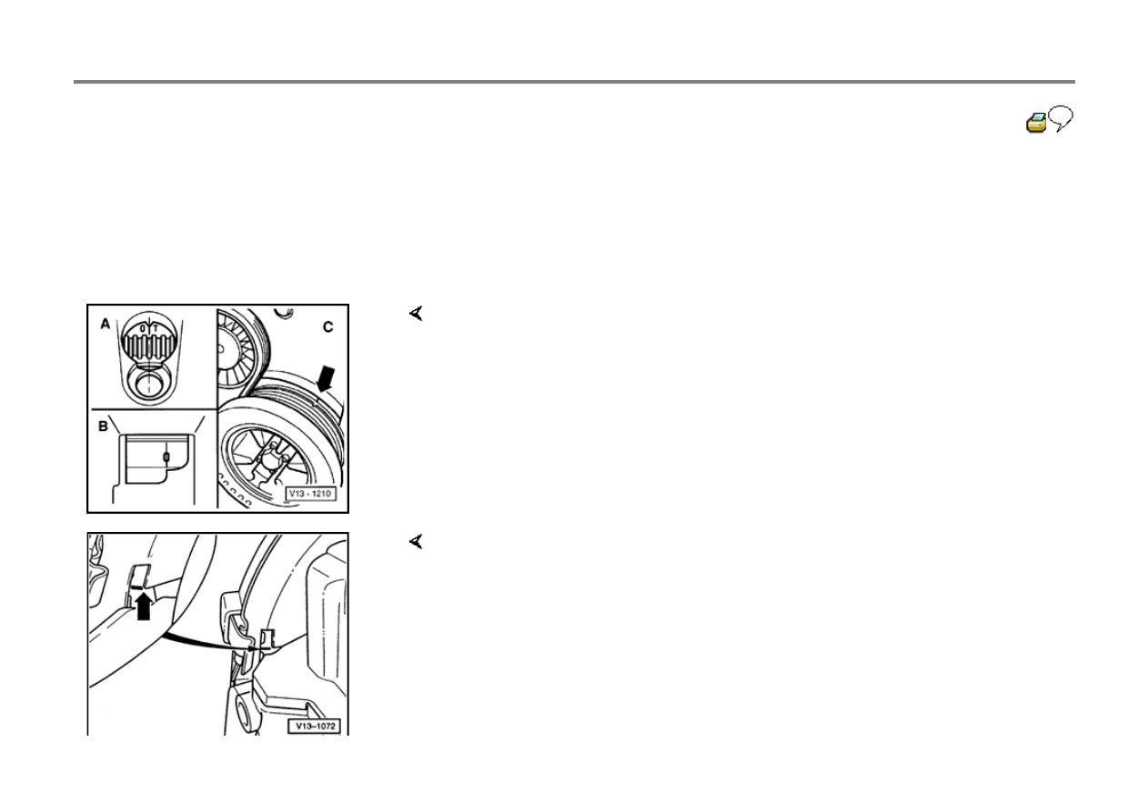
Ignition distributor, installing
Engine installed
- Set flywheel -A- or drive plate -B- to TDC for cyl.
1
Engine removed
- Align marking on vibration damper -C- with marking on lower toothed belt guard -
arrow-
- Align marks on camshaft sprocket with mark on rear toothed belt guard -arrow-
28-30
- Position distributor rotor to point to cyl. 1 mark on housing
- Install ignition distributor
- Before installing, clean distributor cap and check for cracks and signs of tracking,
replace if necessary
- Check and adjust ignition timing

28-31
Ignition timing, checking and adjusting
Special tools, testers and auxiliary items
VAG 1367 Engine Tester using inductive pick-
up VAG 1 367/8
VAG 1551 Scan Tool using adaptor cable VAG
1551/1
Test conditions
Engine oil temperature 80 C (176 F)
minimum
VAG 1551 Scan Tool connected
Test sequence
Note:
On some vehicles a TDC sensor is fitted as
standard. Use adapter cable VAG 1367/9 to
connect to a TDC sensor.
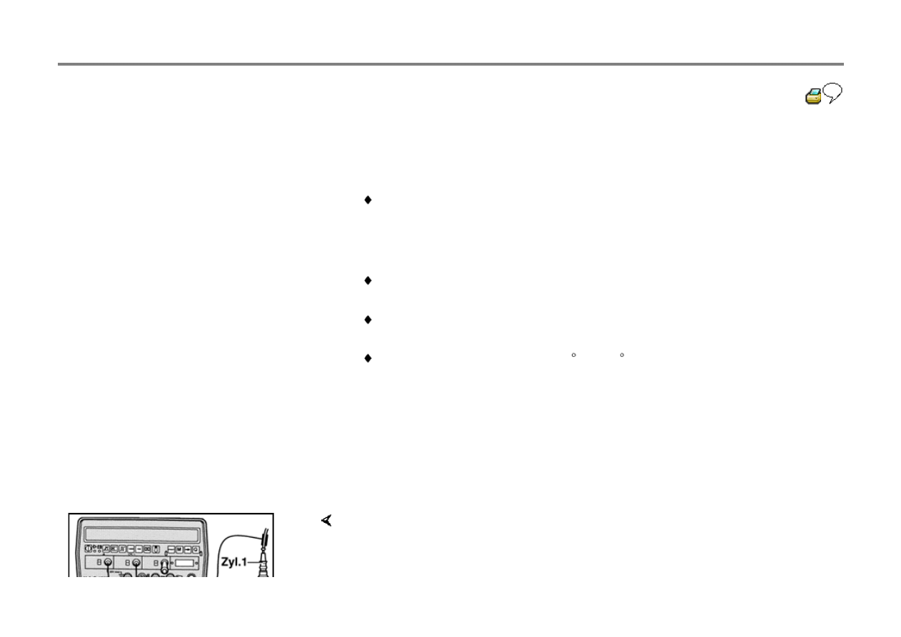
- Connect VAG 1367 Engine Tester using the VAG 1367/8 inductive pickup

Note:
If the engine stalls, after restarting it can automatically run for up to 4 minutes at an
increased speed. In which case do not continue until the speed drops off.
- Start engine and let idle (idle speed not to exceed 1500 rpm)
- Operate Scan Tool taking the displayed information into account
- Press 1 button to select "Rapid data transfer"

28-32
- Press 0 and 1 buttons to select address word
01: "Engine electronics"
- Press Q button to enter input
- Press
button
- Press 0 and 4 buttons to select Function 04:
"Basic setting"
- Press Q button to enter input
Note:
The Digifant Engine Control Module will be
matched to the engine at idle speed, in the basic
setting.
Basic setting
HELP
Input display group number XX
Display will appear as shown
- Press 0 and 1 buttons to select "Display group number"
- Press Q button to enter input
Basic setting 1
1
2
3
4
Display will appear as shown, (1 to 4 = Display zones)
Do not continue with check until

Engine temperature exceeds 85 C (display zone 2)
All setting conditions have been fulfilled Specification: 00000000 (display zone
4)
page 01-78.
- Check ignition timing between 2000 and 2500 rpm
Checking value: 3 to 8 before TDC (fluctuating)
28-33
Using a stroboscope:
- Point strobe at ignition timing mark
- If necessary, adjust ignition timing by turning the distributor
Adjusting value: 6 1 before TDC
- Allow engine to idle for at least 1 minute
- Press
button
- Press 0 and 6 buttons to select Function 06: "End data output"
- Press Q button to enter input
28-34
Ignition timing point, checking
Special tools, testers and auxiliary items
VAG 1367 Engine Tester and inductive pick-up
VAG 1367/8
Test conditions
Ignition timing OK
No malfunctions stored in DTC memory
Engine oil temperature at least 80 C (176 F)
minimum
Test sequence
Note:
On some vehicles a TDC sensor is installed as
standard. Use adaptor cable VAG 1367/9 to
connect the TDC sensor.
- Connect VAG 1367 Engine Tester using VAG 1367/8 inductive pickup
- Start engine and let idle

If timing does not advance
- Set Engine Tester to 2200 rpm
- Slowly raise engine speed to slightly above 2200 rpm until ignition timing
(advance angle) is displayed
specification: 23 to 33 before TDC
- Perform electrical checks, if necessary, replace ECM -J169-
Page 01-83
28-35
Camshaft Position sensor, checking
Special tools, testers and auxiliary items
Fluke 83 multimeter
VW 1594 adaptor kit
VAG 1527B LED tester
Adaptor cable VAG 1315A/4
Test conditions
DTC code "Camshaft Position sensor -G40-"
recognized by On Board Diagnostic
Test sequence
Repair Group 01
Page 01-87
- Perform electrical check, test step 12
Voltage supply, checking

If specifications are obtained
- Disconnect 3-pin harness connector from Camshaft Position sensor -G40-
- Connect multimeter between terminals 1 and 3 of harness connector using VW
1594 adaptor leads
- Switch ON ignition
Specification: At least 10 Volts
- Switch OFF ignition
- Replace Camshaft Position sensor
Page 28-26
, item 5
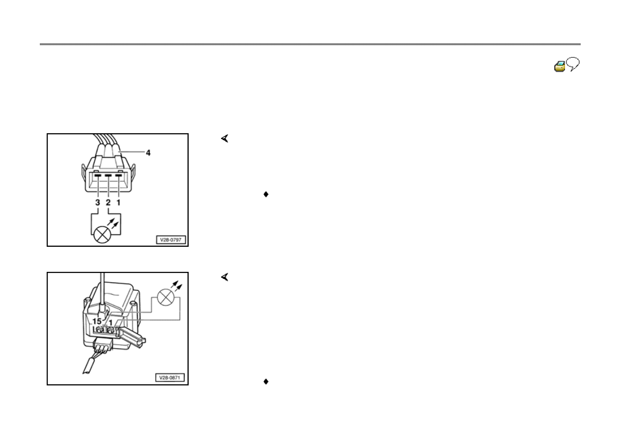
28-36
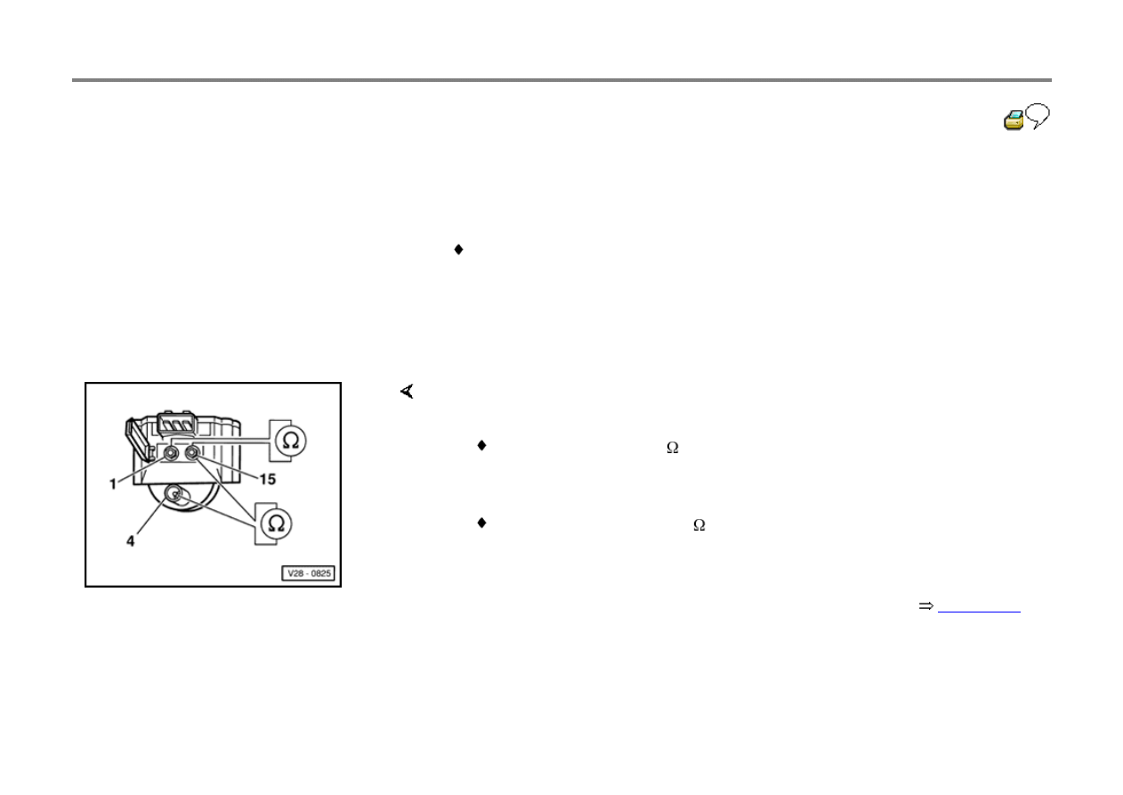
Ignition coil, checking
Special tools, testers and auxiliary items
Fluke 83 multimeter
Test sequence
- Disconnect coil wire from ignition coil and
harness connector from power output stage
If specifications not obtained
- Check primary resistance by connecting multimeter between ignition coil
terminals 1 and 15
Specification: 0.5 to 0.7
- Check secondary resistance by connecting multimeter between ignition coil
terminals 4 and 15
Specification: 3000 to 4000
- Remove ignition coil and disconnect power output stage -N157-
Page 28-23
,
item 5
- Repeat check

28-37
Ignition coil power output stage,
checking
Special tools, testers and auxiliary items
Fluke 83 multimeter
VW 1594 adaptor kit
VAG 1527B LED tester
Test conditions
Camshaft Position sensor OK
Repair Group 01, page 01-85
Electrical check, test step 9 OK, checking
Ignition coil OK
Voltage supply, checking
- Disconnect ignition coil 3-pin harness
connector

- Connect multimeter between terminals 1 and 3 of the harness connector using
jumper leads from the VW 1594 adaptor kit
- Switch ON ignition
Specification: Approx. battery Voltage
- Switch OFF ignition
28-38
Activation, checking
- Remove fuse 18
If the LED does NOT flicker
- Connect VAG 1527B LED tester between terminals 2 and 3 of ignition coil
harness connector using jumper wires and adaptor VW 1594/15 from VW 1594
adaptor kit
- Operate starter and observe ignition signal from ECM
LED must flicker
- Replace Digifant ECM -J169-
- Reconnect ignition coil harness connector and coil wire
CAUTION!
During the following check, do not touch the ignition coil terminals or test
cables!
- Connect LED tester between terminals 1 and 15 of ignition coil using jumper
wires from VW 1594 adaptor kit
- Switch ON ignition
LED must light up for 1 to 2 seconds

- Operate starter
LED must flicker
- Replace ignition coil power output stage, if necessary
Wyszukiwarka
Podobne podstrony:
g3 ign syst aaa 93 95
g3 mfi ign syst aaa 93 95
g3 mfi ign syst aba 93 95
g3 mfi ign syst aba 96 99
g3 mfi ign syst aaa 96 99
Proj syst log wykl 6
syst tr 1 (2)TM 01 03)13
Dyrektywa Dzwigowa 95 16 WE Czesc 1
94, 95
Program Progr Syst i Wspolb2011
Lepiej usługiwać innym niż sobie, Kazania Słowa Bożego, Jacek Filończyk, 02 Usprawiedliwienie przez
pomoc SYST[1].INF, Szkoła
Cechy org jako syst społ
Obwód zasilania 15 (IGN 1) skrzynka bespieczników w kabinie
A New American Acupuncture Acu Nieznany
IR(95) 1927 pl
DYREKTYWA 2006 95 WE dotycząca sprzętu elektrycznego
więcej podobnych podstron