
Introdução
Basic Principles Of Perspective Drawing For The Technical Illustrator
By Kevin Hulsey
A thorough understanding of the principles of perspective is essential to creating an
accurate and visually appealing piece of art. The impression that the techniques in
the preceding tutorial make on the brain are so powerful that once mastered, the
illusion remains even though the visual trickery has been exposed. Additionally, a
lay person with no technical understanding of the principles of perspective has an
intuitive negative reaction to a piece of art if something is amiss.
Any good technical illustration starts with well executed line art. If you are working
from any type of reference other than a CAD output in the desired angle, you will
need to have a strong fundamental understanding of the principles of perspective
drawing. This page will cover the various types of perspective angles you will
encounter. In the tutorial lessons that follow this page, you will be given the tools
needed to map out a perspective grid in any situation. From this grid, you will be
able to create realistic three dimensional drawings from flat or "Off Angle"
reference.
The three photos below demonstrate the difference between 1 Point, 2 Point, and 3
Point Perspective. Fig. 1 is an example of 1 Point perspective. All of the major
vanishing points for the buildings in the foreground of Fig. 1 converge at one
central location on the horizon line. The angle of view or Point Of View (POV) in Fig.
1 is referred to as Normal View perspective. In Fig. 2 the vanishing points for the
two opposing faces of the center foreground building project towards two different
vanishing points on the horizon line. In Fig. 3 we see that the horizontal building
elements project to the left and right horizon and the vertical building elements
project to a central vanishing point in the sky. This upper vanishing point is called
the
. If one were looking down on the object from a Bird's Eye perspective,
the vanishing point below the horizon and would be called the
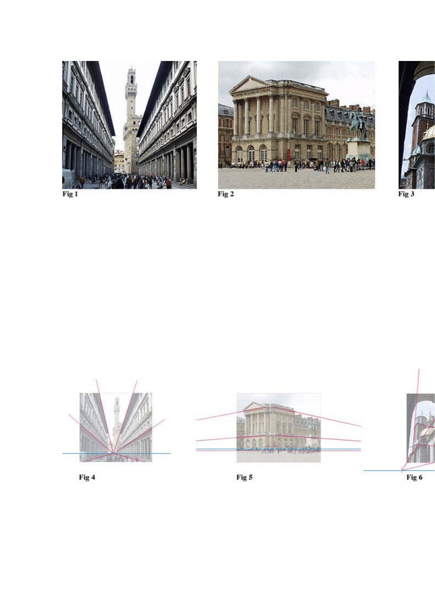
In the next three diagrams, you will see the same three photographs with
Vanishing Point trajectory lines (blue) and Horizon Lines (magenta) traced over the
subject matter. Fig. 4 and Fig. 5 are both examples of Normal View perspective. A
Normal View angle places the Horizon Line at a natural height as if the viewer was
looking straight forward without tilting the head/camera up or down. In these two
examples, you will notice that all of the vertical features of the buildings are
straight up and down.
Fig. 6 is an example of a Worm's Eye perspective. In Fig. 6 the head/camera is
tilted upward placing the Horizon below the picture. The perspective when the view
is tilted in an upward direction, creates a third vanishing point at the
. All of
the vertical building features will converge at this upper vanishing point. If we were
looking down on a subject, the viewing angle would be a Bird's Eye View and the
vertical details would converge at the
.
The following diagram Fig. 7 is a sample of the typical reference material you
might expect to receive on a technical illustration project. All of the major plan and
elevation views are represented here as well as an
view. From this
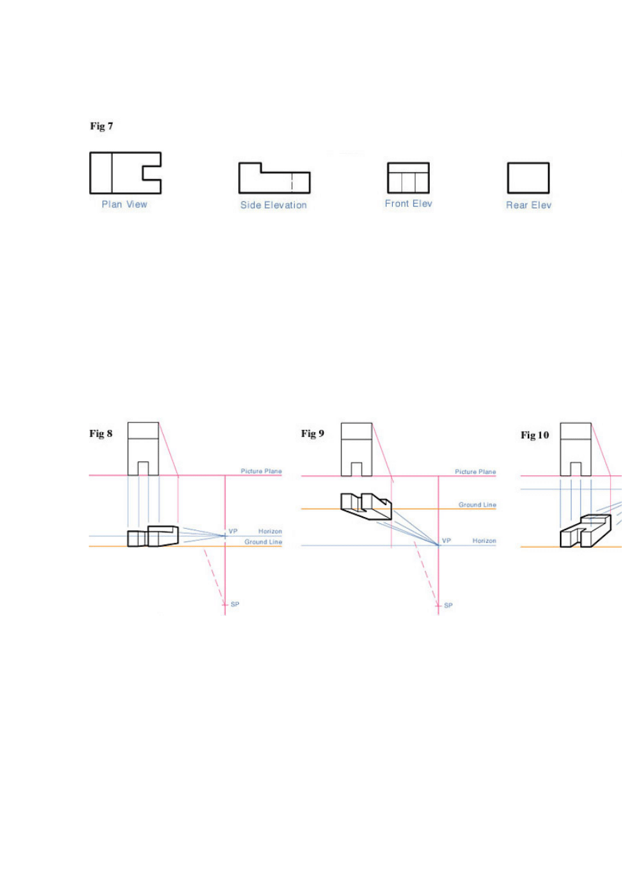
reference, we will construct a variety of perspective views in the tutorials that
follow this page.
In the following six examples, you will see a perspective grid and our subject in
various aspects discussed in the previous paragraph. Fig. 8 is a Normal View 1
Point Perspective drawing. Fig. 9 is a Worm's Eye View 1 Point Perspective
drawing. Fig. 10 is a Bird's Eye 1 Point Perspective drawing. Fig. 11 is a Bird's Eye
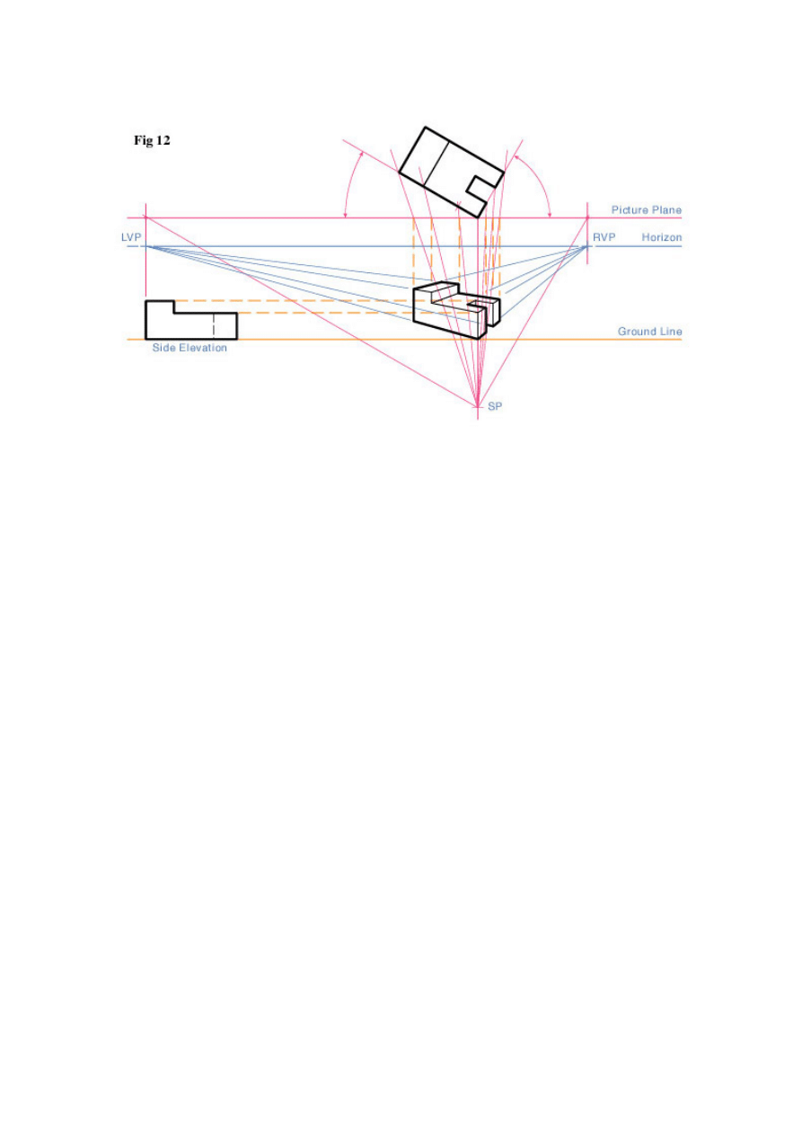
or High 3/4 View 2 Point Perspective drawing. Fig. 12 is a Bird's Eye 3 Point
Perspective drawing. If you were to extend the vertical vanishing point lines
downward, they would converge at the Nadir Station point.
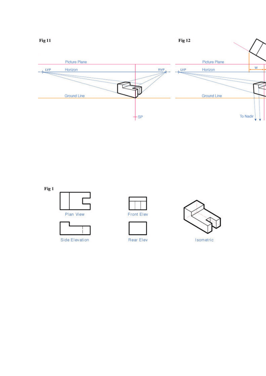
Tutorial Part 1 - Perspective Techniques used in Mechanical Drawing
Lesson in how to map out a 2 point perspective drawing from plan and elevation views.
Software For Line Art: - Adobe Illustrator or other vector program.
In this lesson we are going to create a 2 Point Perspective view drawing of our
subject working from plan and elevation view reference Fig 1. This type of angle is
referred to as a "3/4 Perspective" or "Angular Perspective" view. The green dots in
all of the following diagrams identify the lines to be drawn in the visual example.
The first line to draw will be the Picture Plane Fig. 2. We will place the lower right
corner of our Plan View on the Picture Plane and rotate it clockwise Fig. 3. The
choice of 30 degrees is arbitrary, but this positioning provides a good angle for a
3/4 view drawing. The angle chosen should balance factors such as aesthetics and
information to be conveyed.
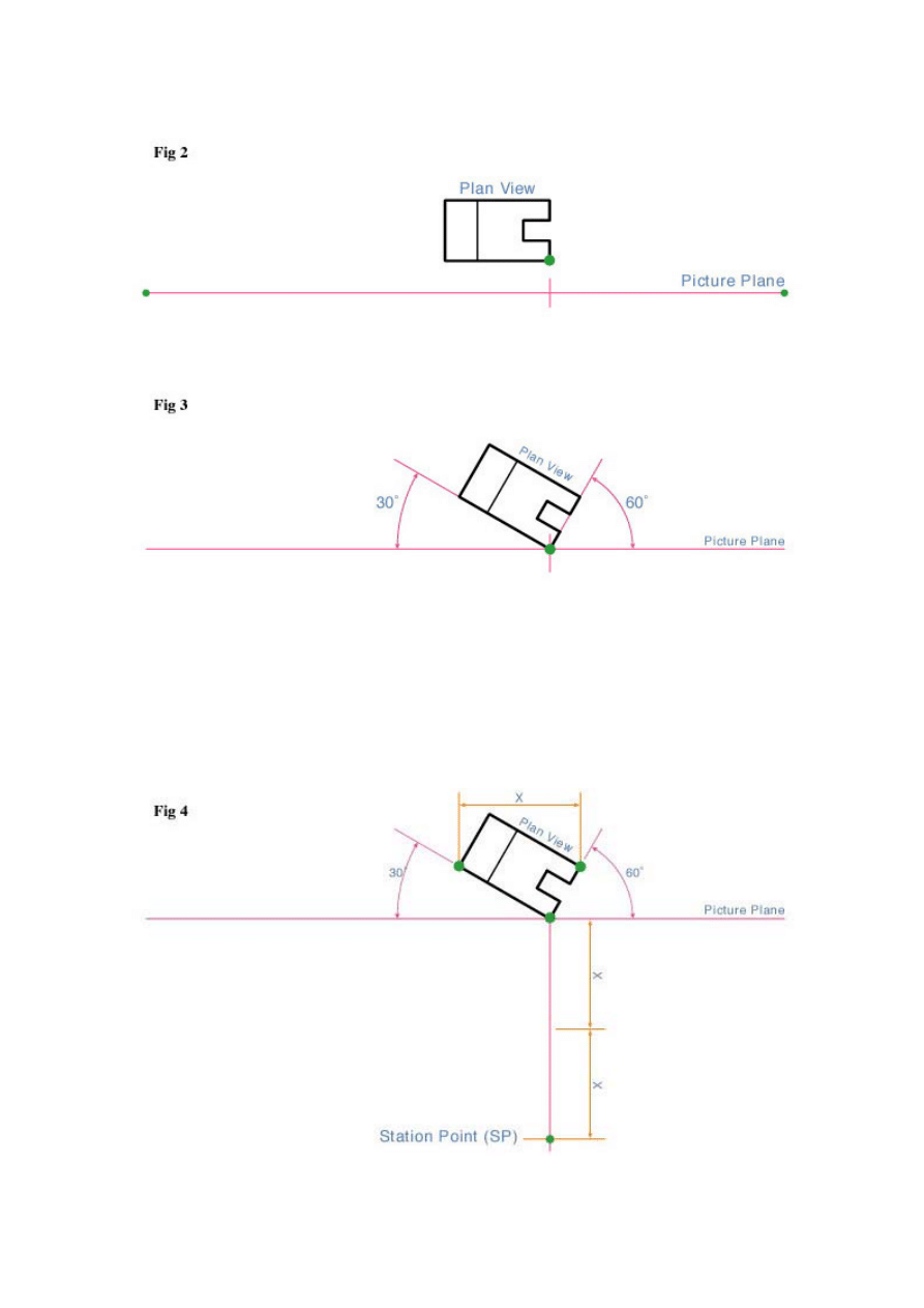
In Fig. 4 we will locate the Station Point. Measure the horizontal width of our Plan
View (X) and double it. Extend a vertical line from the corner that touches the
Picture Plane downward. At two times X we will locate the Station Point.
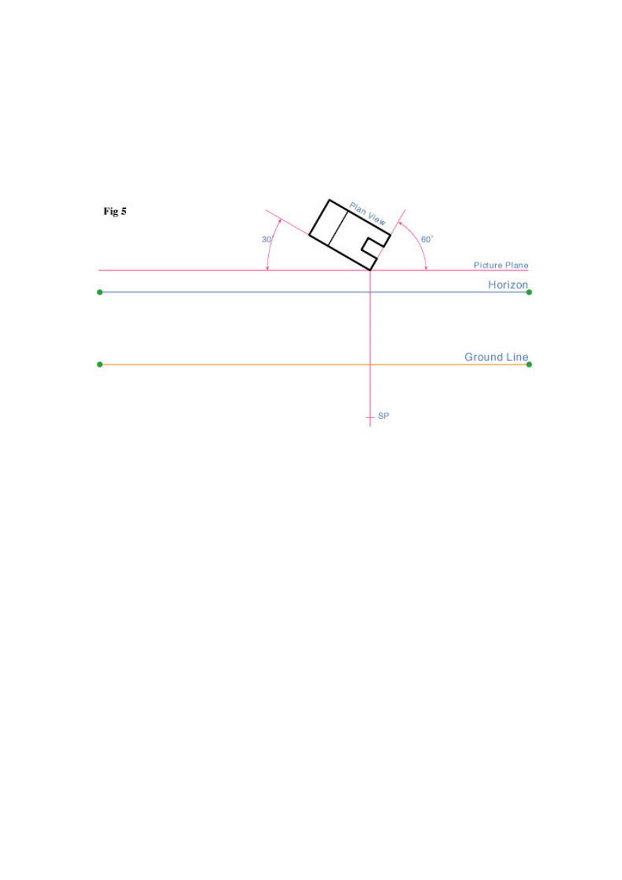
Draw lines for the Horizon and Ground Line Fig. 5. The location of these lines are
infinitely variable. The location of the Horizon Line will depend on whether you want
to view the object from above eye level or below eye level. The location of the
Ground Line in relation to the Horizon Line will determine how far above or below
eye level the object will be viewed.
Draw 2 lines from the Station Point (SP) that are parallel to the bottom edges of
the Plan View Fig 6. The lines should intersect with the Picture Plane (points a & b).
Next draw vertical lines from points a & b to the Horizon Line. The point where
these vertical lines intersect the Horizon Line is where the left and right vanishing
points (LVP & RVP) will be located.
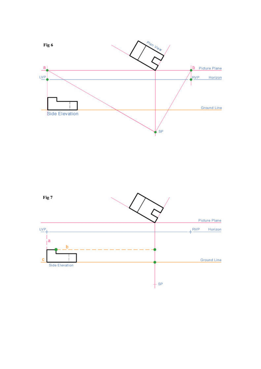
The last part of our preliminary layout will be to place the Side Elevation view from
Fig. 1 onto the Ground Line. Project a line (orange dashed line b) from the top of
the Elevation View to the vertical Line Of Sight (LS) Fig. 7.
We are now ready to start projecting lines to the vanishing points. Referring to Fig.
8, draw lines from both vanishing points (LVP & RVP) to the top and bottom
reference points of our subject (points a & b).
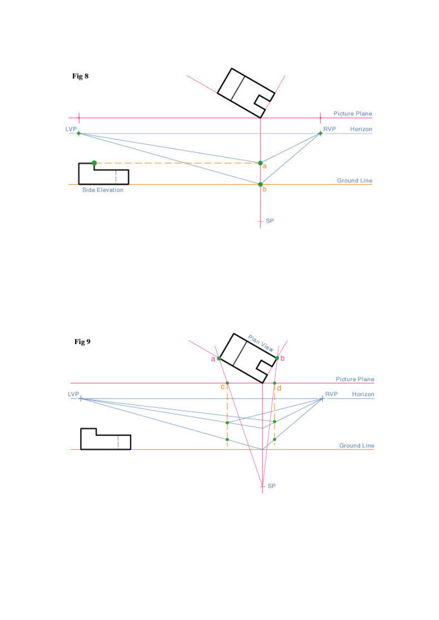
To locate the vertical lines on our subject, draw lines from the Station Point to
corners a & b on the Plan View Fig. 9. At the point where these lines intersect the
Picture Plane, draw vertical lines (orange dashed lines) downward to intersect the
vanishing point projection lines.
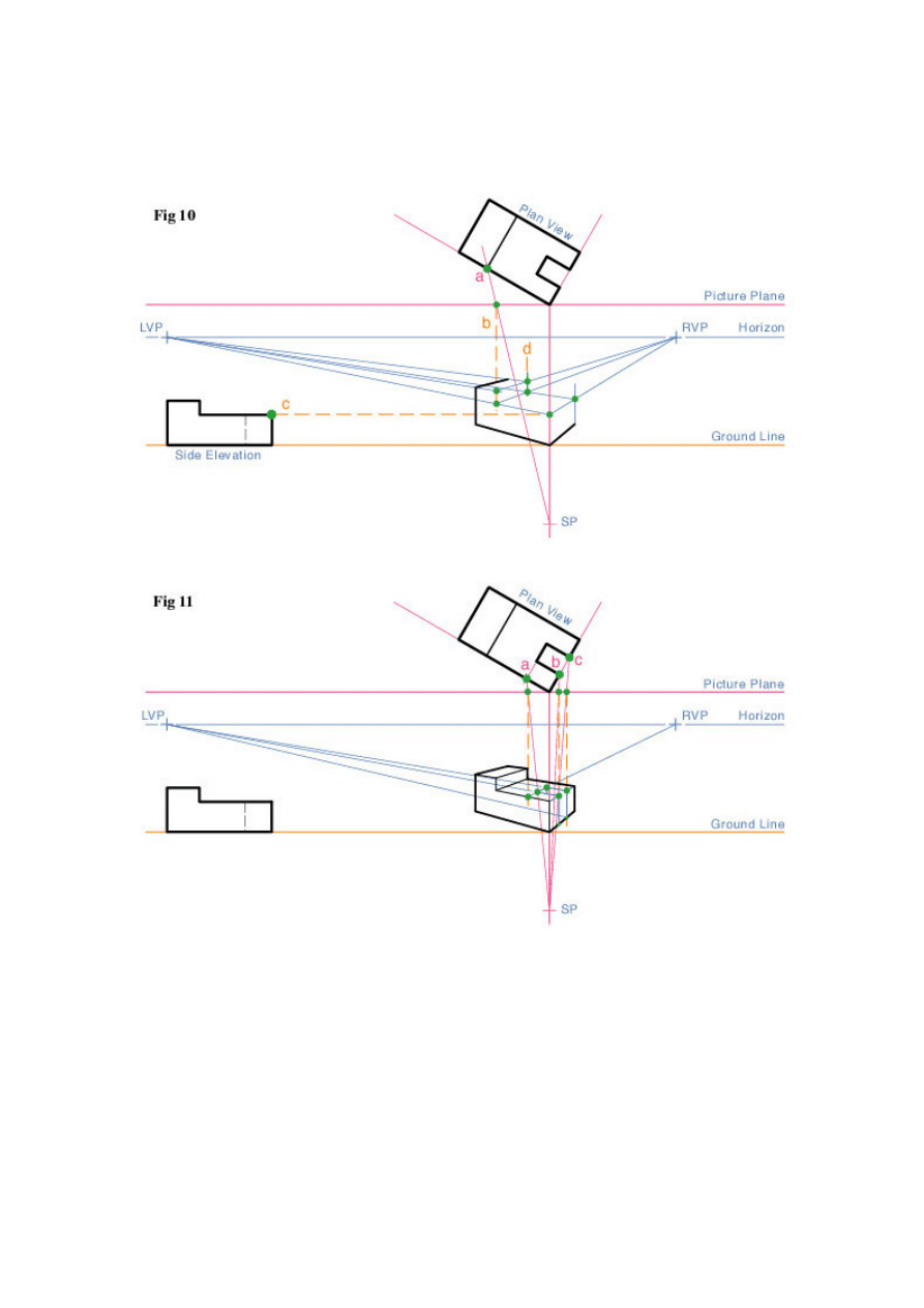
Using the same procedure as shown in Fig. 9, find the smaller features on the
subject in both the Plan View and the Elevation View (a & c) in Fig. 10 and project
them towards the vanishing point projection lines.
The last step is to darken the object's construction lines, and add weight to all of
the exterior and outside edge lines, to increase readability Fig. 12.
Document Outline
- Basic Principles Of Perspective Drawing For The Technical Il
- Tutorial Part 1 - Perspective Techniques used in Mechanical
Wyszukiwarka
Podobne podstrony:
Communist League Basic Principles of the Communist League (2005)
Reading Price Charts Bar by Bar The Technical Analysis of Price Action for the Serious Trader Wiley
Hutter, Crisp Implications of Cognitive Busyness for the Perception of Category Conjunctions
Drawing for the Absolute and Utter Beginner
van leare heene Social networks as a source of competitive advantage for the firm
Bearden Tech papers Master Principle of EM Overunity and the Japanese Overunity Engines (www cheni
S Belavenets Basic principles of game are in middlegame (RUS, 1963) w doc(1)
Vlaenderen A generalisation of classical electrodynamics for the prediction of scalar field effects
Basic Principles Of Celestial Navigation James Allen
Validation of a test battery for the selection of call centre operators in a communications company
Drawing for the Absolute and Utter Beginner
Rewicz, Tomasz i inni Isolation and characterization of 8 microsatellite loci for the ‘‘killer shri
Evaluation of HS SPME for the analysis of volatile carbonyl
British Patent 2,812 Improvements in Methods of and Apparatus for the Generation of Electric Current
Bob Miller s Basic Math and Pre Algebra for the Clueless R Miller (McGraw Hill, 2002) WW
Canadian Patent 29,537 Improvements in Methods of and Apparatus for the Electrical Transmission of P
Energetic and economic evaluation of a poplar cultivation for the biomass production in Italy Włochy
Dynamic gadolinium enhanced subtraction MR imaging – a simple technique for the early diagnosis of L
więcej podobnych podstron