
WIPER/WASHER SYSTEM
1993 Mitsubishi Montero
1993 ACCESSORIES & EQUIPMENT
Mitsubishi Wiper/Washer Systems
Montero
DESCRIPTION & OPERATION
All models are equipped with a 2-speed wiper motor with an
optional intermittent wiper feature. Some models are equipped with a
rear wiper/washer.
ADJUSTMENTS
FRONT WIPER ARM ADJUSTMENT
Ensure wiper motor is in park position. Position wiper arm
and blade assembly so tip of blade is specified distance above front
window trim. See FRONT WIPER ADJUSTMENT SPECIFICATIONS table.
FRONT WIPER ADJUSTMENT SPECIFICATIONS TABLE
Application Specification
In. (mm)
Driver’s Side ........................... .98-1.38 (25-35)
Passenger’s Side ....................... 1.38-1.77 (35-45)
(1) - Information is not available from manufacturer.
REAR WIPER ARM ADJUSTMENT
Ensure wiper motor is in park position. Position wiper arm
and blade assembly so tip of blade is specified distance from edge of
window. See REAR WIPER ADJUSTMENT SPECIFICATIONS table.
REAR WIPER ADJUSTMENT SPECIFICATIONS TABLE
Model In. (mm)
Montero ................................ 2.56-2.95 (65-75)
TESTING
FRONT WIPER MOTOR TEST
Checking Wiper Motor Operation
Disconnect wiring connector from wiper motor. Connect battery
voltage to wiper motor connector as shown, and ensure wiper motor
operates at low and high speeds. See Fig. 1.
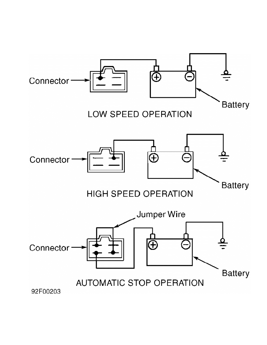
Fig. 1: Checking Front Wiper Motor Operation
Courtesy of Mitsubishi Motor Sales of America.
Checking Automatic Stop
1) Operate wiper motor at low speed. See Fig. 1. Disconnect
battery voltage during operation to stop motor.
2) Using a jumper wire, connect terminals as shown. See
Fig. 1. Connect 12 volts to indicated terminal, and ground wiper motor
bracket. Ensure wiper arm is correctly parked.
INTERMITTENT WIPER RELAY (FRONT) TEST
NOTE: Intermittent wiper relay is incorporated into wiper switch.
Information on testing is not available from manufacturer.
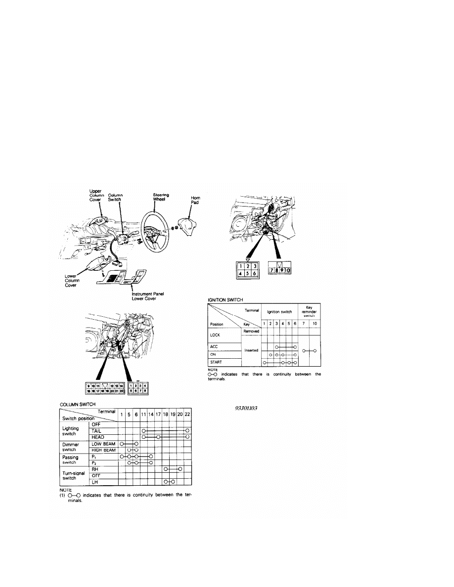
FRONT WIPER SWITCH TEST
Front wiper switch is part of combination switch on steering
column. For steering column switch testing, see Fig. 2.
Fig. 2: Testing, Removing & Installing Steering Column Switches
Courtesy of Mitsubishi Motor Sales of America.
REAR WIPER MOTOR TEST
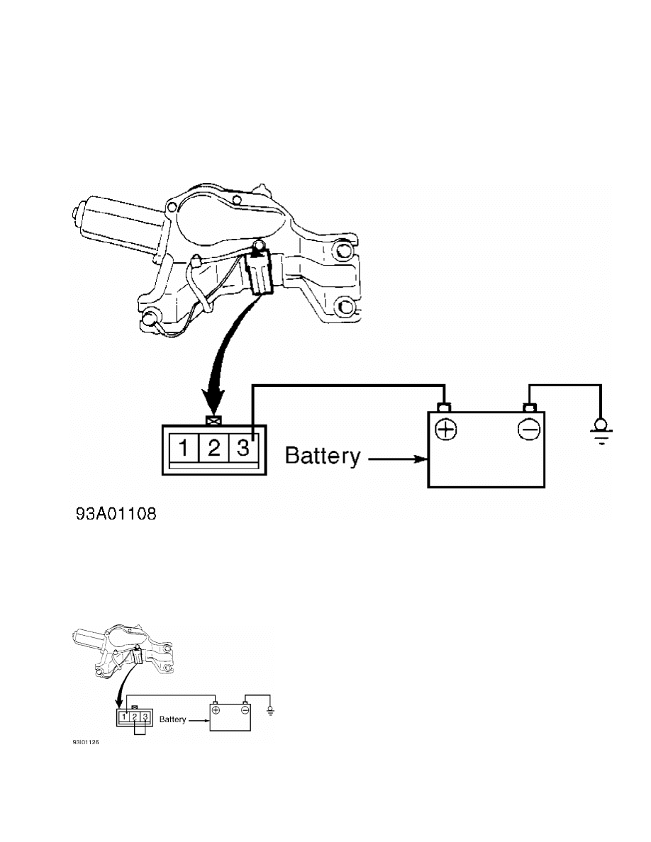
Operational Check
Disconnect wiring connector from wiper motor. Connect battery
voltage to wiper motor connector as shown, and ensure motor housing is
well grounded. Motor should run at low speed. See Fig. 3.
Fig. 3: Rear Wiper Motor Operational Check
Courtesy of Mitsubishi Motor Sales of America
Automatic Stop Check
Operate wiper motor, and then disconnect wiring connector
from wiper motor to stop motor operation at a point other than park
position. Connect battery voltage and jumper wire to wiper motor
connector as shown, and ensure motor housing is well grounded. See
Fig. 4. Motor should return to park position.
Fig. 4: Rear Wiper Motor Automatic Stop Check
Courtesy of Mitsubishi Motor Sales of America
REAR WIPER RELAY TEST
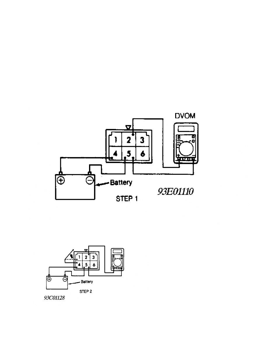
Operational Check
1) Relay is on left side of steering column, behind dash.
Disconnect relay from wiring harness. Connect positive voltmeter lead
to terminal No. 2. Connect negative voltmeter lead to terminal No. 5.
Connect battery voltage to terminal No. 4 and ground terminal No. 5.
See Figs. 5-7.
2) Jumper terminals No. 1 and 4 for 2 seconds. Remove jumper.
Jumper terminals No. 1 and 5 for about 8 seconds. Voltmeter should
show zero volts. After terminals No. 1 and 5 have been connected for
at least 8 seconds, battery voltage should be present on terminal No.
2. Replace relay if voltage is not as specified.
Fig. 5: Rear Wiper Relay Terminal ID (Step 1)
Courtesy of Mitsubishi Motor Sales of America.
Fig. 6: Rear Wiper Relay Terminal ID (Step 2)
Courtesy of Mitsubishi Motor Sales of America.
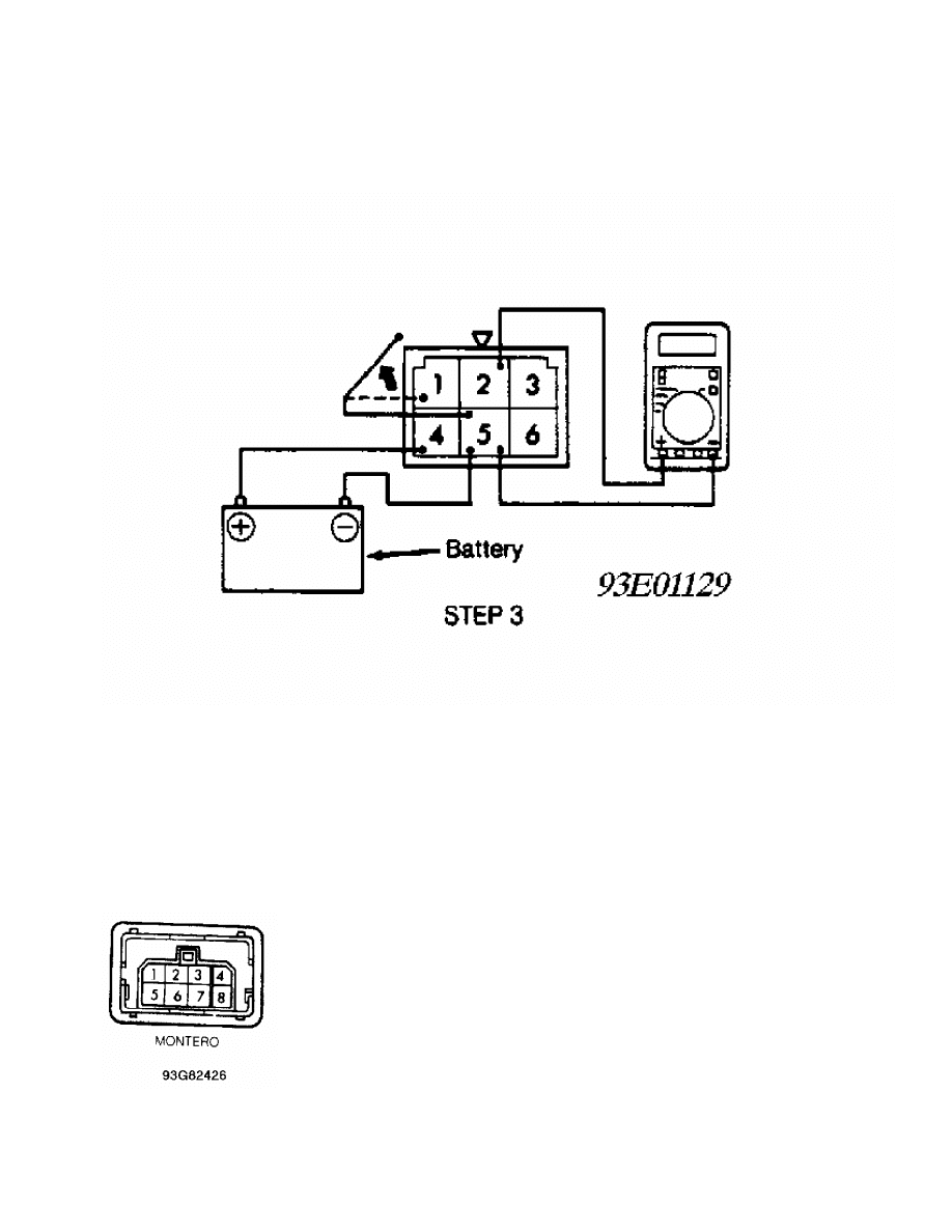
Fig. 7: Rear Wiper Relay Terminal ID (Step 3)
Courtesy of Mitsubishi Motor Sales of America.
REAR WIPER SWITCH TEST
Remove wiper switch from instrument panel and disconnect
wiper switch. Place wiper switch in OFF position. Continuity should
exist between terminals No. 4 and 7. See Fig. 8. Place wiper switch in
ON position. Continuity should exist between terminals No. 2 and 7.
Place wiper switch in INT position. Continuity should exist between
terminals No. 4 and 7, and between terminals No. 1 and 6. Depress
washer switch. Continuity should exist between terminals No. 2 and 3.
Fig. 8: Rear Wiper Switch Terminal ID
Courtesy of Mitsubishi Motor Sales of America.
REMOVAL & INSTALLATION

FRONT WIPER MOTOR
Removal & Installation
Remove wiper motor bolts. Pull motor out just slightly.
Disconnect wiper linkage from motor assembly and remove motor. To
install, reverse removal procedure.
FRONT WIPER SWITCH
WARNING: DO NOT hammer on steering wheel. Collapsible steering column
mechanism may be damaged.
Removal & Installation
Remove instrument panel under cover. Remove horn pad. Remove
steering wheel. Remove upper and lower steering column covers. See
Fig. 2. Remove column switch. To install, reverse removal procedure.
REAR WIPER MOTOR
Removal & Installation
Remove wiper blade and arm assembly. Remove tailgate trim, 2
bolts and wiper motor. To install, reverse removal procedure. Ensure
grommet is in good condition.
REAR WIPER RELAY
Removal & Installation
Relay is located on left side of steering column, behind
dash.
REAR WIPER SWITCH
Removal & Installation
Pry rear wiper switch from instrument panel and disconnect
wiper switch. To install switch, reverse removal procedure.
WIRING DIAGRAMS
See appropriate chassis wiring diagram in the WIRING DIAGRAMS
section.
Wyszukiwarka
Podobne podstrony:
76 WIPER WASHER SYSTEM
WIPER & WASHER SYSTEM 9D 24
05 10 F01 Wiper Washer System
WIPER WASHER SYSTEM
96ZJ 8K WIPER AND WASHER SYSTEMS
93ZJ Secc 8K Windshield Wiper and Washer Systems
M39d Wipers Washer Systems
BMW E38 schematic Wiper washers
8252 Windshield & headlamp wiper & washer inspection
wiper washer
66 Wiper and Washer
66 Wiper and Washer
66 Wiper and Washer
66 Wiper and Washer
66 Wiper and Washer
Toyota Avensis y Corrolla Esquema cableado wiper and washer
System finansowy w Polsce 2
Systemy operacyjne
więcej podobnych podstron