31.05.21
Motorola Confidential Propriet
ary
1
Overview of flip PCB
Display connector
CLI connector
Hinge flex connector
ATI 2282
Camera connector

31.05.21
Motorola Confidential Propriet
ary
2
Cannot take picture (1)
1.
Download the software image (1FF) into the problem unit and recheck the camera function
2.
Open the flip and check whether the connector is properly inserted
3.
Take out and plug in camera connector again
4.
Change camera module
5.
Check the camera plug and receptacle under microscope
6.
Check whether the camera flex is damaged or not
7.
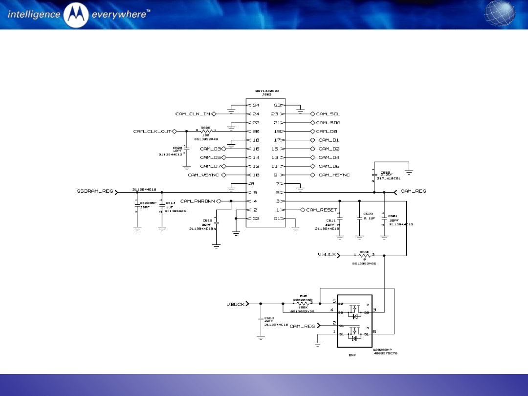
Check all the signals between ATI 2282 and camera module when starting camera function:
i.
Input signals
•
CAM_RESET = High
•
CAM_PWRDWN = low
•
CAM_CLK_IN = 15.37MHz
•
VCAM = 2.8V; VBUCK = 1.8V; GSDRAM = 1.8V
•
CAM_SCL and CAM_SDA
ii.
output signals
•
CAM_CLK_OUT=50.9MHz
•
CAM_D[0]-[7]
•
CAM_HSYNC
•
CAM_VSYNC
31.05.21
Motorola Confidential Propriet
ary
3
Cannot take picture (2)
schematics of camera connector
31.05.21
Motorola Confidential Propriet
ary
4
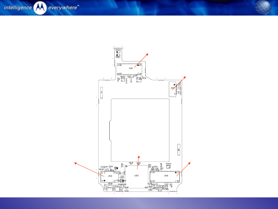
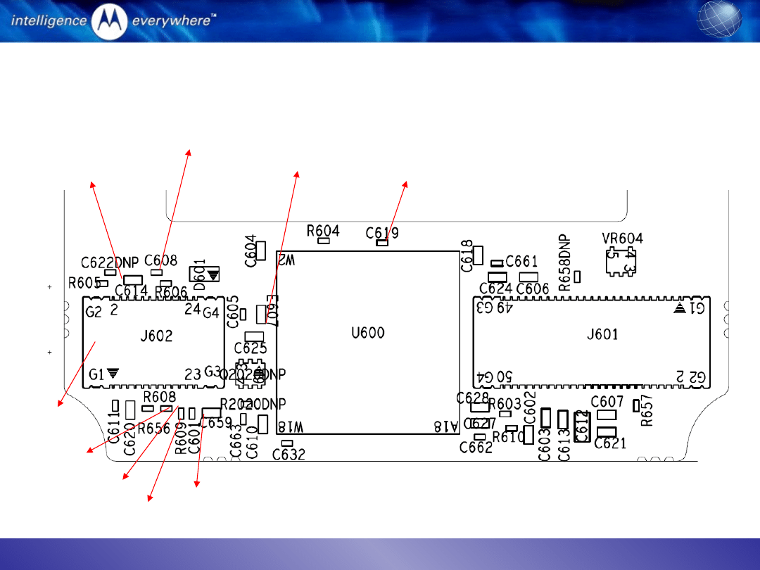
Cannot take picture (3)
Signal positions to probe
CAM_CLK_IN
CAM_CLK_OUT
Camera connector
CAM_PWRDWN
CAM_REG
VBUCK
GSDRAM_REG
CAM_SCL
CAM_SDA

31.05.21
Motorola Confidential Propriet
ary
5
Camera abnormal
Camera blemish in viewfinder mode
•
Check whether the cover lens is clean or not
•
Remove whether there is particle inside the camera lens under microscope
•
Change camera module
Camera color abnormal
•
Open the flip and make sure the connector is properly inserted
•
Take out and plug in camera connector again to check the issue is resolved or not
•
Check the plug and receptacle under microscope
•
Probe camera data lines and see any signal is missing
•
Change camera module if the problem is due to the module
Camera flickering
•
Check whether the flickering is due to display and camera
•
Check the power frequency used in the region: 50Hz or 60Hz
•
Use RadioComm to read out the flicker setting: Element iD: 0x4A, Record #:0x1; offset:
0x1C8; Length:0x01: if the value read back is 0x01, it is for 50Hz; if the value is 0x02, then
it is for 60Hz. This value need to be matched to the AC power frequency used in the region.

31.05.21
Motorola Confidential Propriet
ary
6
Display abnormal
If only main display is abnormal:
–
Check whether any LED is not functional
–
Download the software image into the problem unit
–
Open the flip and check whether the display connector is properly inserted
–
Take out and plug in the display connector again
–
Change a display module
–
Check the 40 pin receptacle under microscope
–
Check whether the display flex is damaged or not.
If CLI display is abnormal:
–
Open the flip and check whether the ZIF connector is pressed properly or not
–
Change to a new CLI display
–
Check whether the original CLI display is cracked or flex damaged
If both CLI and main display are missing:
–
Download the software image into the problem unit
–
Change a flip and see whether the issue is gone
–
Change a main board and see whether the issue is gone
–
Change the hinge flex
–
Check the open and short on the signal LCD_DATA[0]-[7],LCD_RS, LCD_CS, LCD_RD, and
ATI_RESET
31.05.21
Motorola Confidential Propriet
ary
7
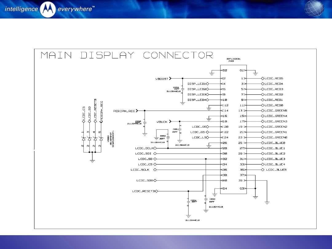
Display schematics
Document Outline
- Overview of flip PCB
- Cannot take picture (1)
- Cannot take picture (2) schematics of camera connector
- Cannot take picture (3) Signal positions to probe
- Camera abnormal
- Display abnormal
- Display schematics
Wyszukiwarka
Podobne podstrony:
KB04 SMD DISPLAY
Diagnostic Trouble Code (DTC) D Nieznany
2 4 Troubleshooting Labid 20091
e984 38x sysplan & installman appb & troubleshooting
HP CJJ 5 troubleshooting
Kody Mitsubishi Trouble, Kody błędów DTC PL
Plant Display
Kody Kia Trouble, Kody błędów DTC PL
pat troubleshooting
Photoshop-Dodatki i instrukcje, Adobe ImageReady, Adobe ImageReady
Ignition TroubleShooting
Popular Mechanics Saturday Mechanic Troubleshooting Distributorless Ignitions
Mahjongg trouble es
Display A Z
easy500 Text display HLP EN
Disposal Trouble
Jvc Power Supply Description And Trouble Shooting Procedure
4c 5 3 2 4 Lab Troubleshooting Inter VLAN Routing PL
evoluation of displacement
więcej podobnych podstron