Demystifying Cable Performance
The many claims about cable and interconnect performance makes it hard on enthusiasts who just
want a wideband, low-noise, harmonic and dynamic presentation. Furutech’s Pure Transmission
Technology engineers are devoted to eliminating common problems in each and every element of
power and signal transmission – especially magnetic and EMI (Electro Magnetic Interference)
distortion.
For example, all metal parts go through Furutech’s 2-Stage Alpha Super Cryogenic and
Demagnetizing Process before assembly. The Ground Jumper System neutralizes magnetic fields
around the screws holding power connectors closed so they don't interfere with the larger magnetic
field around the power cord! Every Reference III cable features an external module filled with
Formula GC-303 EMI-absorbent material.
Cable Basics
A quality cable design depends on three basic factors: Conductor material, insulation material, and
construction.
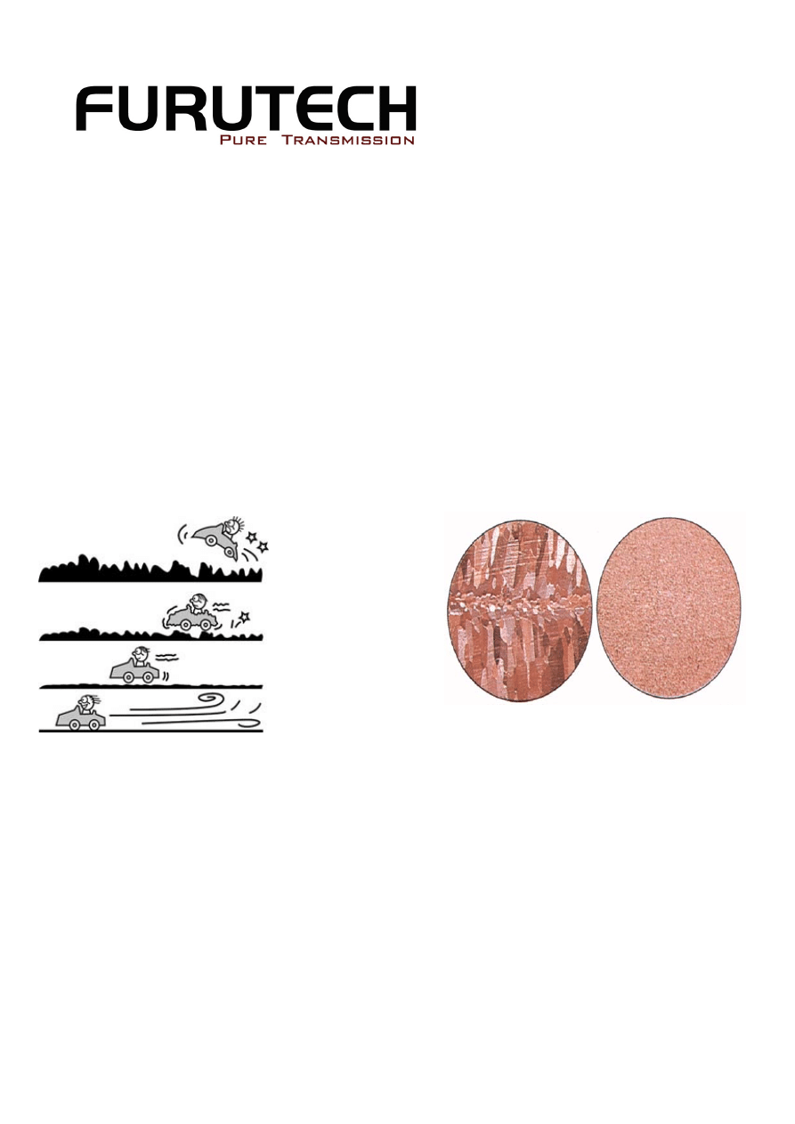
TPC Alpha-OCC
TPC
OFC
μ-OFC
Alpha-OCC
Grain Structure
TPC (Tough Pitch Copper) is basic copper wire conductor typically found in power cords and
occasionally inexpensive audio cables. Drawing melted, electrolyzed copper through a series of
dies, the conductor is cooled to size. Tough pitch copper melted and cooled in “open air” carries
about 300~500ppm of oxygen.
OFC (Oxygen Free Copper) conductor is processed in an oxygen-free, inert-gas environment, and
its 10ppm of oxygen content is a significant improvement over TPC. OFC conductivity is 0.5% to 2%
greater than TPC as a result.
μ-OFC (Annealed Oxygen Free Copper) is manufactured by precisely controlling time and
temperature constants to reduce the formation of crystal grain structures.
Ohno Continuous Casting Improved
Furutech introduced Furukawa Electric cables to the market in 1988, the first PCOCC A/V cables
and interconnect featuring high purity single-crystal oxygen-free copper. Ohno Continuous Casting,
invented by Professor Ohno at The Chiba Institute of Technology in Japan, yields very pure copper
conductors. Furutech engineers have applied themselves to continued improvement in every aspect
of signal and power transfer, resulting in our own state-of-the-art α Alpha-OCC conductor material.
A high temperature heated mold produces mono or single crystal ultra pure copper wire with
insignificant traces of oxygen and hydrogen, reducing the ratio of stress to strain within the wire.
Since Ohno Continuous Casting produces a flexible wire, a higher specific gravity and higher “Q”, its
mechanical isolation and resistance to electromagnetically-induced vibration is excellent. Furutech
OCC monocrystal wire has no crystal grain boundaries within the conductor to interfere with signal
flow with the lowest distortion factor of any cables available!
Our Alpha-OCC is the only OCC featuring Furutech’s 2-Stage Cryogenic and Demagnetizing Alpha
Process, resulting in high performance cables at all our price points.
Furutech 2-Stage Cryogenic and Demagnetization Alpha Process
Furutech developed a two-stage process significantly improving every element of audio and video
performance. The treatment begins with a deep, conditioning cryogenic freeze of all metal parts,
including conductors and connectors.
Using high-end refrigerants - liquid N
2
or He - Furutech achieves between -196 to -250C. At these
extremes of temperature the metal parts actually change molecular structure, removing internal
stress. Molecules bond together more tightly and the overall structure becomes more stable.
Cryogenic treatment enhances electrical conductivity, power and signal transfer.
Stage two in the Alpha Process exposes these same parts to our patented Ring Demagnetization
Treatment. Ordinary high power magnets often increase magnetization effects and leave some
areas more magnetized than others. Just like a CD spinning over a fixed magnet; when the CD
stops the area above the magnet is still exposed to the magnet’s field. The patented Ring
Demagnetization Process uses controlled attenuation to eliminate all field effects for immediately
more vivid and colorful improvements. Ring Demagnetization further enhances conductivity of all
treated materials.
All metal parts used in Furutech products are given the 2-Stage Alpha treatment, and Furutech’s
deMag keeps your interconnect, speaker cable, power cord and connectors in perfect demagnetized
condition.
Construction
Most high performance cables use solid-core conductors or stranded “wire lays” depending on its
purpose. Stranded cables are typically available in one of three configurations, each having its own
characteristics.
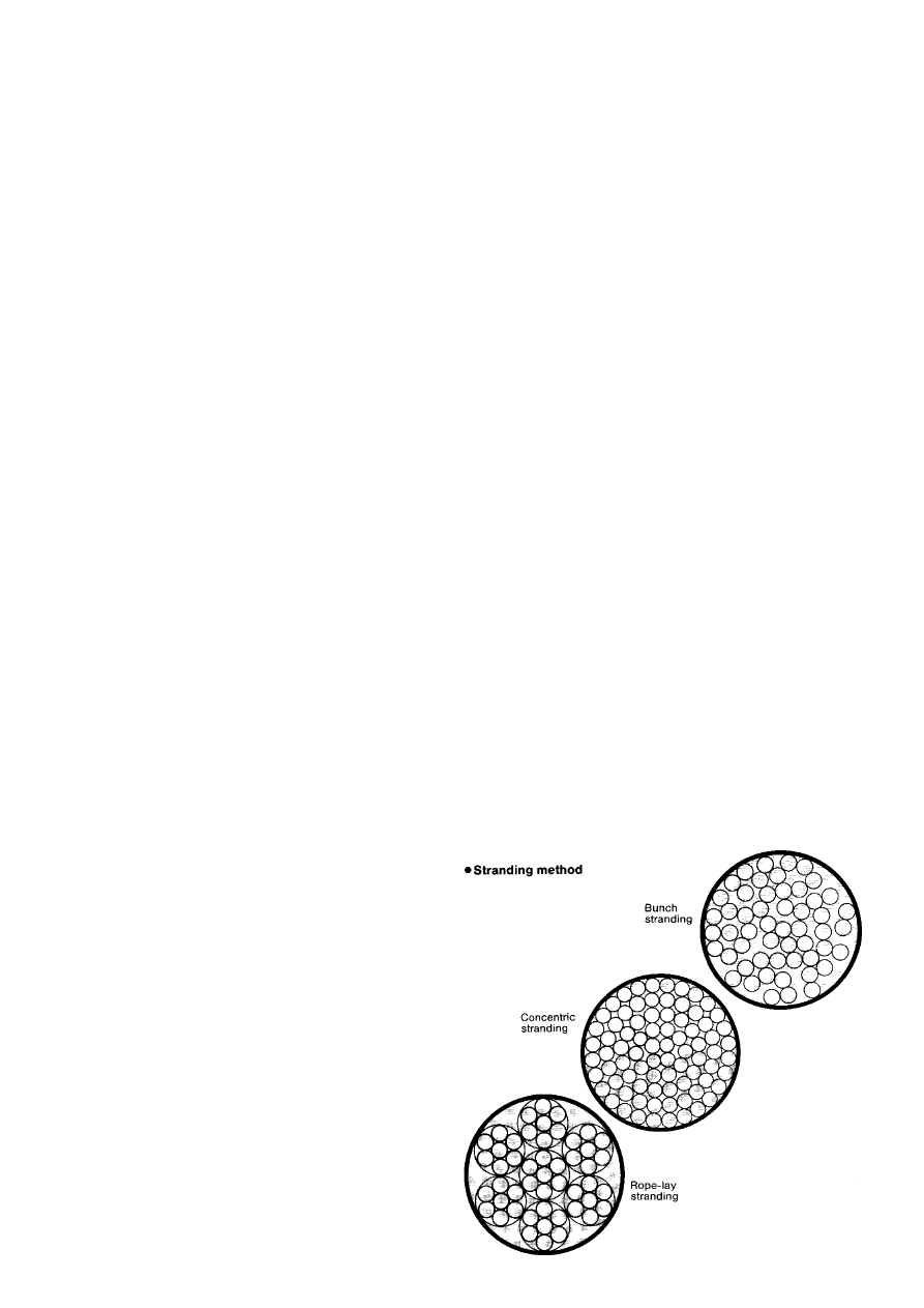
Stranded Conductors
Many basic power cables and interconnect
use simple, stranded conductors. They’re
simple loose copper conductors arrayed in a
group or bunch from connector to connector.
One major problem: Examining its cross
section, you’ll see the bundle of wires at the
perimeter of the bundle bunch up or separate.
This results in signal-degrading reflections
caused by fluctuating impedance.
Concentric Lay Stranded Conductors
A concentric lay consists of multiple layers of
concentrically wound stranded conductors.
The center of the middle conductor coincides
with the center of all other conductors. Most
importantly the uniform layout of the
conductors form a perfect circle when viewed in cross section, improving performance by stabilizing
impedance fluctuations.
Rope Lay Stranded Conductors
Rope lay conductors are composed of concentric-lay stranded conductors consisting of bunched or
concentric-lay stranded wires. Rope lay stranding is often used in better quality speaker cables that
require a large and flexible cross section.
Solid-Core Conductor
Solid-core Furutech Alpha-OCC conductors are the ultimate in signal transfer materials. Furutech’s
perfectly circular solid-core conductor, produced in a variety of sizes, eliminates each and every
problem above.
Understanding Cable Performance
There are three essential electrical characteristics that affects the sound of cable expressed as
LCR – characteristic impedance (L), capacitance (C), and resistance (R).
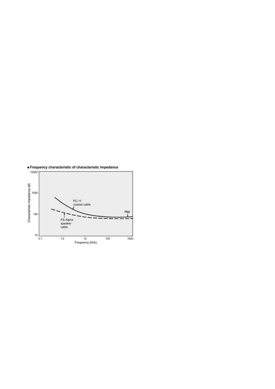
Characteristic Impedance (L)
Impedance is easily explained using a 75 ohm coax S/PDIF digital connection as an example.
Maintaining correct impedance from one end of the cable to the other is critical for high frequency
signal transfer. Mismatched impedance values create reflections within the cable causing timing
errors and jitter by interfering with digital’s step rise/fall time.
Capacitance (C)
Capacitance (C) represents the electrostatic capacitance of a cable determined by the relative
position of the two conductors and the dielectric constant of the insulation. Foamed polyethylene
and polypropylene are used in low-capacitance cables like Furutech’s FC-11, and FA-220, where
foaming reduces the dielectric constant and stabilizes frequency characteristics. Within the audio
range the amount of capacitance together with conductor resistance governs the level of attenuation,
the lower the better.
Resistance (R)
Resistance (R) is signal loss - attenuation - of energy is absorbed by the cable during signal transfer
that’s directly proportional to the conductor’s resistance. This is especially so in speaker cable
where high resistance causes a decreased damping factor. The voice coil of the driver generates an
electromotive force feeding back through the speaker cable that in extreme cases can damage the
amplifier. DC resistance is in direct proportion to the conductor’s cross-sectional area and purity of
materials. Keep the cable’s diameter as large as possible, use the highest purity wire possible, and
DC resistance will be low.
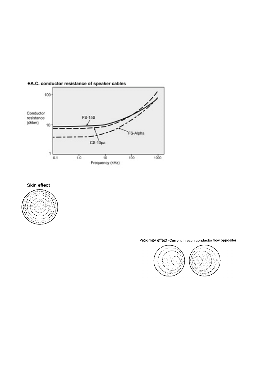
Further Considerations
A conductor’s resistance also increases because of Skin Effects, Proximity Effects, and Eddy
Current Losses. Illustrated below are frequency characteristics of three Furutech speaker cables,
CS-10pa, FS-Alpha and FS-15S. The first two are stranded designs with 2mm square and 5.5mm
square conductors respectively, the third 1.5mm square solid-core conductor.
Notice that from 20Hz to 20kHz - the audible frequency range - all three cables remain relatively flat.
However, as frequency increases from DC to AC conductor resistance increases. These frequencies
may be inaudible, but they directly affect timbre, air and ambience, focus, detail, and imaging.
Skin Effect
As frequency rises current migrates towards the conductor’s surface. Current
traveling across a conductor’s peripheral surface changes the effective cross-
sectional area resulting in greater resistance, causing signal loss with degraded
sound and image quality.
Proximity Effect
High frequency currents flowing in the same
direction placed side by side tend to flow with a
certain distance between them. When the current
flows opposite each other, the current tends to flow
towards each other, increasing resistance.
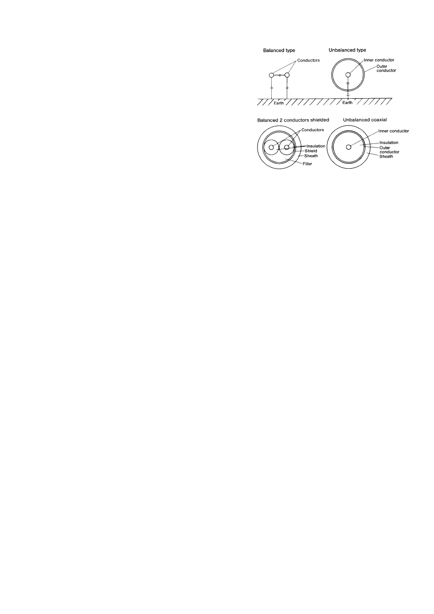
Balanced and Unbalanced Cables
Balanced conductors offer the same characteristic
impedance, capacitance, and resistance (LCR).
Conductors remain at equal ground potential and don’t
reference ground. Balanced cables may feature separate
shields for radiated noise. In some cases the shield is
connected to a flying lead - an external wire - for
connection to chassis ground.
Unbalanced single-ended cable on RCA terminations are
dissimilar conductor-to-conductor in construction and
electrical characteristics. Single-ended coaxial cables tie
the shield to the return signal path - the outside barrel of
the RCA connector. In general, the resistance of the shield
is lower than that of the conductor enhancing its effect.
The Shield
Interconnects are shielded to protect the signal from external radiated noise. There are two types of
shield; one rejects electrostatic noise, the other magnetic noise.
Damping electrostatic noise requires a metalized shield with a high-conductivity constant, such as
copper or aluminum foil. Since the shield’s effect is in reverse proportion to its resistance, reducing
resistance increases current flow, creating a more effective barrier against external noise. Furutech
balanced cables use copper wire braid and aluminum foil shields with insulated conductors twisted
around each other.
Ferrous material shields against magnetic interference, but cables can become thick and unwieldy
unless carefully engineered. Generally speaking, twisting the insulated conductors around each
other in a “hum-bucking” cable lay does suppress magnetic fields. But Furutech’s engineers
consider this insufficient protection and prefer an effective ferrous-based solution.
Furutech uses Formula GC-303, a special 3M material layered and bonded to the interior bottom-
plate of our power distribution and filtering units. It absorbs EMI (Electromagnetic Interference)
that’s generated by the wire junctions inside the unit, and can also be found in the modules that
surround the Reference III cable products.
Insulation
The most popular insulation materials are PVC (polyvinyl chloride) and LDPE (low-density
polyethylene). You’ll find PVC in commercial low-voltage applications of 600V or less. LDPE, with its
improved dielectric characteristic, is preferred for high-voltage power applications, as well as video
and digital cables.
FEP (Teflon) and PP (polypropylene) are also used as insulation material. Teflon has excellent
dielectric characteristics along with superior heat resistance. That’s helpful when you consider the
insulation is applied at extrusion temperatures of about 400 to 500 degrees centigrade; at these
temperatures, the conductor surface oxidizes.
PP (polypropylene) is a pure, stable material with excellent insulation characteristics, including its
dielectric constant. PP also exhibits better mechanical isolation from vibration and it’s Furutech’s
favored insulation for speaker cables and line-level interconnects.
The efficiency of the insulation’s dielectric constant determines the signal transmission velocity. All
Furutech cables and interconnect are engineered for low dielectric loss and stable frequency
response throughout the audio spectrum.
Insulation Materials’ Electrical Characteristics
Material
Properties
Low Density Polyethylene
(LDPE)
PVC Polypropylene
FEP
Specific volume resistance
(Ωwcm 20℃)
>10
17
10
12
~10
15
6.5 X 10
14
>10
18
Dielectric constant
(50~10
6
Hz)
2.3 4~8
2.25
2.1
Dielectric loss
tangent
(50~10
6
Hz%)
0.02~0.05 8~15
0.02~0.06 0.02~0.07
*
Teflon is a trademark of Du Pont.
As above, insulating materials have four electrical characteristics that are critical to signal transfer
function: Specific volume resistance, resistance per unit area of DC (direct current), and the index of
insulation performance
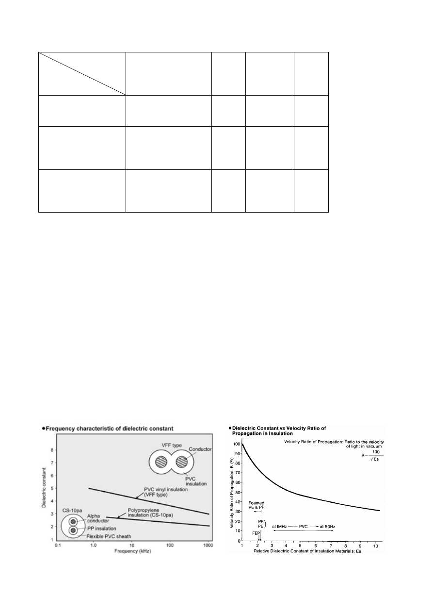
Dielectric strength is the voltage at which 1mm of insulation breaks down. Dielectric loss tangent is
a guideline for dielectric loss as AC is applied to insulation material. The Relative Dielectric Constant
(Es) is probably the most important element in a cable’s design. It’s defined as the ratio between the
electrostatic capacitance for parallel plates in a vacuum (Co) and the electrostatic capacitance when
an insulation material is interposed (C). It is expressed as Es=(C/Co). The relative dielectric
constant may be interpreted as the magnitude of polarization for the vacuum (Es=1).
As seen in the graph below right, an insulating material containing a large volume of ions such as
PVC polarizes when voltage is applied. The altered structure of the insulation surrounding the
current-carrying signal conductor causes dielectric loss, resulting in reduced transmission velocity
based on the insulation’s relative dielectric constant.
The graph lower left illustrates the frequency characteristics of relative dielectric constants (Es)
between two sample cables, Furutech VVF, a power cable using PVC insulation, and Furutech CS-
10pa speaker cable, with PP insulation and a PVC sheath.
Jacketing
Furutech’s attractive jacketing material mechanically dampens external vibration as well as
electromagnetically-induced resonance. It even bends with relative ease!
Sounds Like?
The result of all this engineering is sound with a greater sense of power, dynamics, and resolution,
with cleaner, blacker backgrounds and a larger, more stable soundstage, with a vivid tonal colors
and deeper extension at both ends of the frequency range. Our video cables allow displays of all
types to show greater, sharper resolution with less ghosting, color shift, “snow”, or vertical and
horizontal lines.
A few precautions for optimal performance:
•
Do not wind, bundle or bind cables
•
Do not stretch
•
Do not bend excessively
•
Do not place signal carrying cables in parallel with power cables
•
Do not place audio cables in parallel with ferrous materials
•
Do not leave one end of any cable connected with the other not
•
Do not allow hot and cold signal paths to touch and short circuit
•
Disconnect unused cables
•
Do not attempt to fix a solder connection within the cable
•
Periodically clean any oxidation from the contacts
•
Do not use unnecessarily long runs where possible
Furutech dealers will be pleased to assist with an obligation free, in-home demonstration of
the very special sonic improvements of Furutech cables.
Make More Powerful Connections with Furutech
Additional Information
Physical and Chemical Properties of Copper Ingot
Alpha-OCC
μ-OFC OFC TPC
Purity >99.997
>99.99
>99.99
>99.9
× 8.938
8.928
8.926
8.75
Density
max 8.940 8.934
8.932
8.88
O
2
(ppm) <5
<10
<10
200~500
Gas impurity
H
2
(ppm)
<0.25
<0.5
<0.5
>0.3
Hydrogen Embrittlement
None
No
No
Yes

Properties of Materials
Alpha-OCC
μ-OFC OFC/
TPC
Conductor diameter
5mm
15mm
1.6mm
0.9mm
Length of grain
>500mm
>50mm
<0.3mm
<0.05mm
Length of grain after
drawn to 0.1mm
>1,125.00m <12cm
<4mm
Number of grains in 2m
cable
1 >30
>400
Wyszukiwarka
Podobne podstrony:
Abolicja podatkowa id 50334 Nieznany (2)
4 LIDER MENEDZER id 37733 Nieznany (2)
katechezy MB id 233498 Nieznany
metro sciaga id 296943 Nieznany
perf id 354744 Nieznany
interbase id 92028
Mbaku id 289860 Nieznany
Probiotyki antybiotyki id 66316 Nieznany
miedziowanie cz 2 id 113259 Nieznany
LTC1729 id 273494 Nieznany
D11B7AOver0400 id 130434 Nieznany
analiza ryzyka bio id 61320 Nieznany
pedagogika ogolna id 353595 Nieznany
Misc3 id 302777 Nieznany
cw med 5 id 122239 Nieznany
więcej podobnych podstron