Fuses and relays
4-1
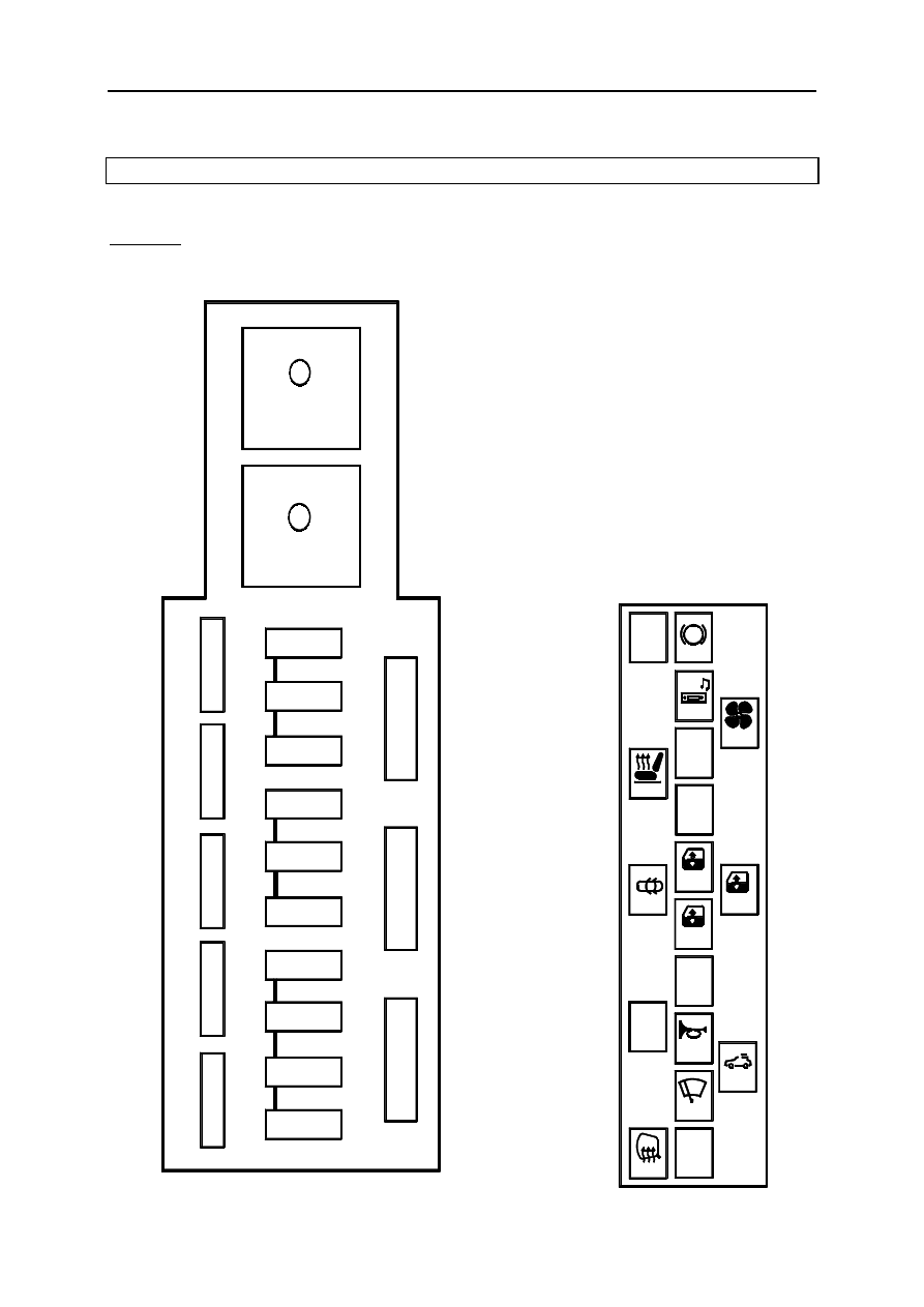
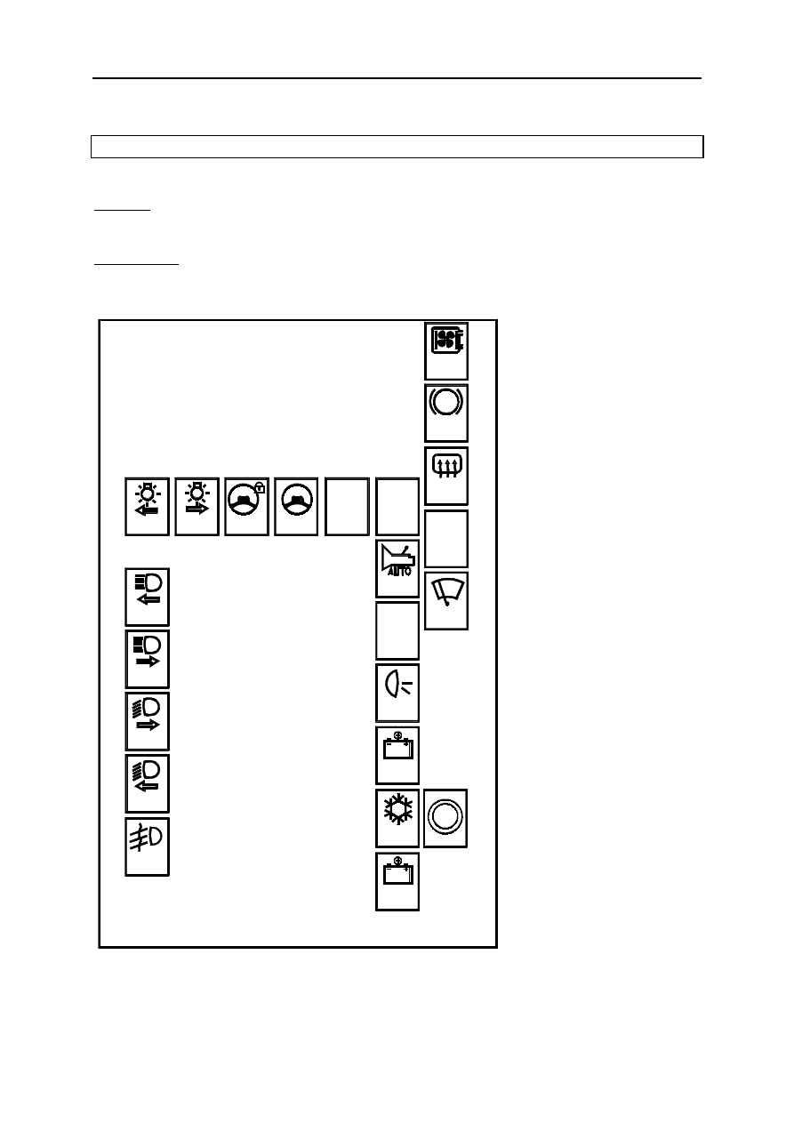
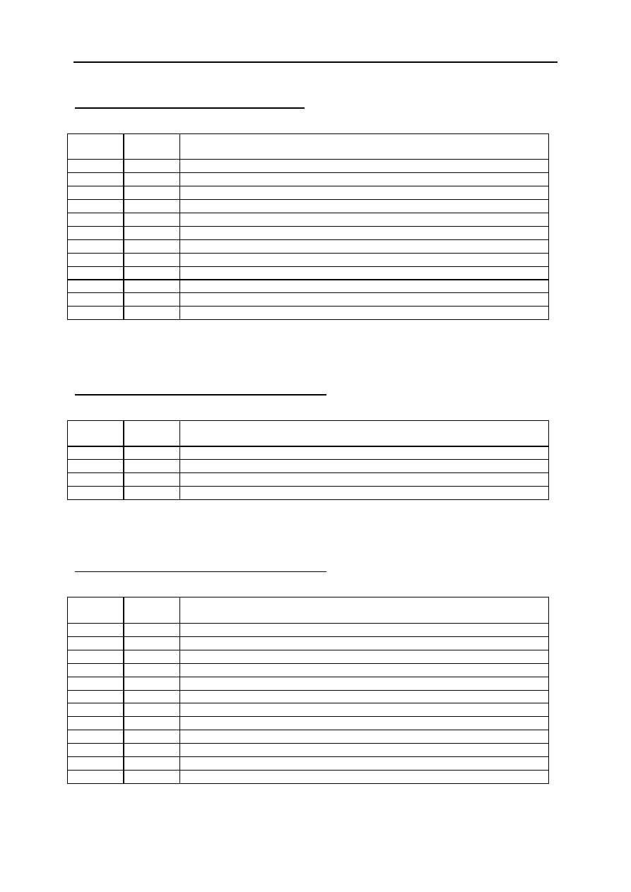
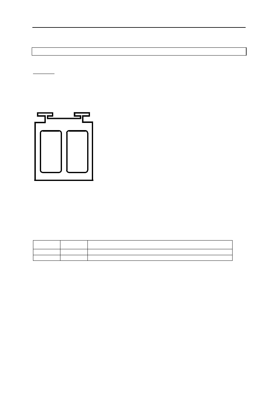
PASSENGER COMPARTMENT RELAY AND FUSE BOX (260)
Location
This fuse box is located in the passenger compartment on the driver’s side.
SE2158
F
G
H
K
L
N
O
M
P
R
V
W
U
S
T
B
A
E
D
C
ABS
15 A
STOP
25 A
25 A
15 A
S E 2 1 5 7
COUPE
CONSO
ALIM
U C H
7.5 A
20 A
20 A
20 A
20 A
15 A
15 A
40 A
20 A
10 A
30 A
Fuses and relays
4-2
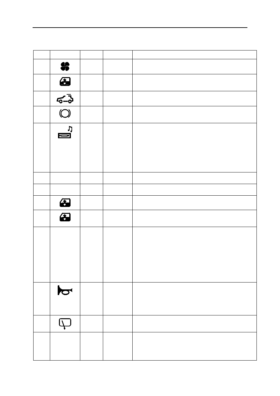
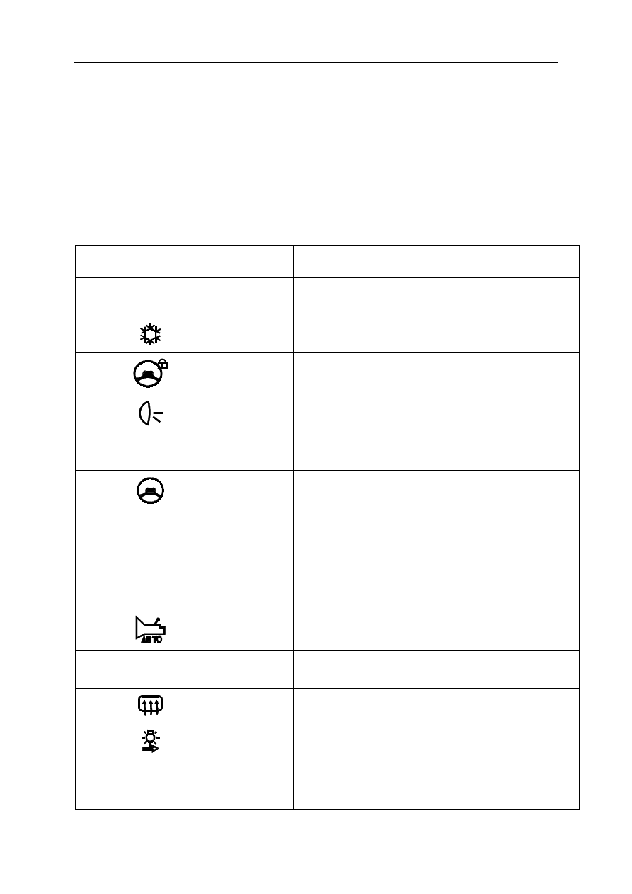
Allocation of fuses and relays (according to equipment level)
No. Symbol Amps
Connection
Description
C
40A SP3
Fuse: passenger compartment ventilation (319)
D
30A/40A BP87
/BP48
Fuse: rear electric windows (201-202) or electric windows
relay (703).
E
20A BP93
Fuse: electric sun roof (304)
F
ABS
10A SP15
Fuse: ABS computer (118) or Electronic Stability Program
(1094)
G
15A SP2
Fuse : radio (261)- multifunction display (653)- headlight
washer pump relay (753)- headlight washer pump relay 2
(1338)- cigarette lighter (first row) (101)- passenger and
driver's heated seat (385-386)- front and rear dual
direction window washer pump (677)- diesel fuel heater
relay (450)- climate control panel (319)- AC control unit
(419)- rigid retractable roof computer (1476)- interior rear-
view mirror (1340).
H
15A SP17
Fuse: brake lights (160-1524)
K --
--
not in use
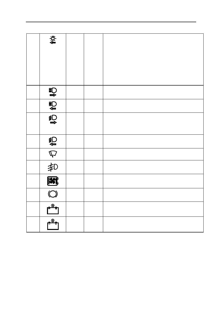
L
25A BP55
Fuse: driver's electric window (203)
M
25A BP70
Fuse: passenger electric window (204) - electric windows
relay (703).
N
COUPE
20A BCP3
Fuse: consumer cut-out
- radio (261)
- multifunction display (653)
- electric door mirror switch (134)
- alarm control unit (427)
O
15A BP32
Fuse: main electromagnetic horn (105) - diagnostic
socket (225) - headlight washer pump relay (753) -
headlight washer pump relay 2 (1338) - rigid retractable
roof computer (1476) - driving school monitor control
(469)
P
15A BP25
Fuse: rear screen wiper motor (211)
R UCH
SUPPLY
20A BP77
Fuse: UCH (645)- instrument panel (247)- AC control unit
(419)- accessories relay 1 (260 mark B)
Fuses and relays
4-3
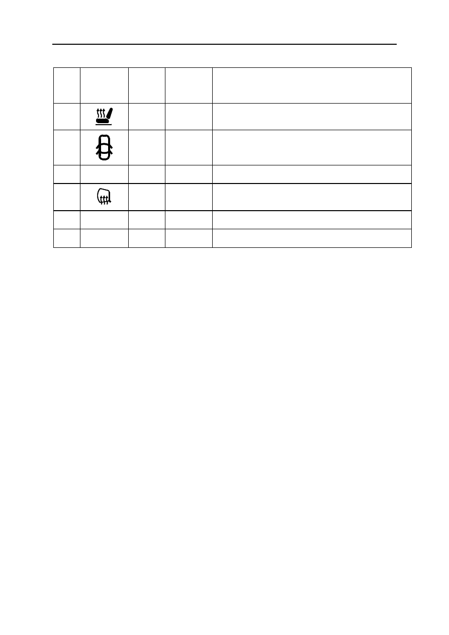
S 3A AP1A
Fuse: passenger compartment temperature sensor fan
(418) - interior rear-view mirror (1340) - light and rain
sensor (1415)
T
20A BPR1
Fuse: passenger and driver's heated seat (385-386)
U
20A BP3
Fuse: electric door locking or deadlocking (138-139-140-
141-645-844-1322)
V -- --
Not in use
W
7.5A 15RP
Fuse: passenger and driver's heated door mirrors (239-
240)
A 40A
Relay: electric window (703)
B 40A
Relay: accessories 1 (1155)
Fuses and relays
4-4
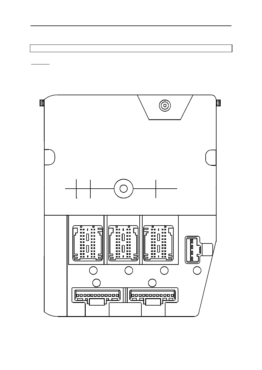
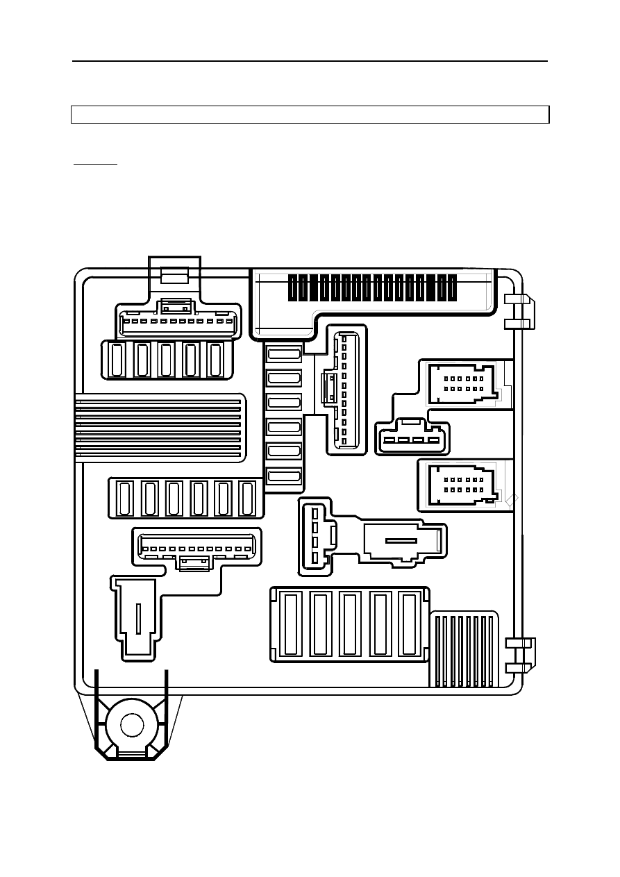
UCH (645)
location
This fuse box is located in the passenger compartment on the driver’s side.
20
11
GR
11
1
PE3
PP2
31
21
30
40
20
12
PE2
NO
1
21
31
10
40
30
S E 2 1 6 0
PP1
GR
PE1
21
30
1
PP3
NO
1
31
10
40
12
BA
1
11
10
20
1
4
NO

Fuses and relays
4-5
Allocation (according to the equipment level)
PE1 (40-track connector) WHITE
BROWN
Track Connection
Description
1
26J
Safety Hall sensor control
2
47Z
External temperature / display signal
3
64F
Hazard warning light + control
4
26BC
Card position LED control
5
26X
Clutch - signal
6
20AW
One-touch door locking/unlocking control
7
26N
Engine start/stop + signal
8
87T
Rear luggage compartment door notch 1 switch signal
9
20T
Child safety LED - control
10
--
Not in use
11
20AL
Rear internal locking control
12
16A
Front washer pump + control
13
26M
Engine running warning light control
14
20M
Door locking LED
15
87G
Passenger notch 1 switch signal
16
87B
Right-hand rear notch 1 switch - signal
17
87H
Driver notch 1 signal switch - signal
18
20BG
Rear doors deadlocking state signal
19
87A
Left-hand rear notch 1 switch - signal
GREEN
Track Connection
Description
20
--
Not in use
21
--
Not in use
22
--
Not in use
23
--
Not in use
24
--
Not in use
25
--
Not in use
26
--
Not in use
27
--
Not in use
28
--
Not in use
29
--
Not in use
30
--
Not in use
31
--
Not in use
32
--
Not in use
33
--
Not in use
34
--
Not in use
35
--
Not in use
36
--
Not in use
37
--
Not in use
38
--
Not in use
39
--
Not in use
40
--
Not in use

Fuses and relays
4-6
Allocation (according to equipment level)
PE2 (40-track connector) BLACK
BROWN
Track Connection
Description
1
14S
Rain sensor series line signal
2
141H
Information display control signal line 5 under steering wheel
3
47C
External air temperature sensor + signal
4
141D
Information display control signal line 3 under steering wheel
5
141N
Information display control signal column 4 under steering wheel
6
CANH
CAN H fault finding signal
7
21K
Anti-pinch sunroof electric window series line signal
8
133B
Instrument panel CAN H signal > ECU
9
141K
Information display control signal column 1 under steering wheel
10
26AZ
Keyless vehicle steering column lock CAN H signal
11
141G
Information display control signal line 4 under steering wheel
12
141C
Information display control signal line 2 under steering wheel
13
47D
External temperature sensor 0V signal
14
141B
Information display control signal line 1 under steering wheel
15
141L
Information display control signal column 2 under steering wheel
16
CANL
CAN L fault finding signal
17
141M
Information display control signal column 3 under steering wheel
18
133C
Instrument panel CAN L signal > ECU
19
141P
Information display control signal column 5 under steering wheel
20
26BA
Keyless vehicle steering column lock CAN L signal
GREEN
Track Connection
Description
21
26BH
+ Card reader
22
38JV
Passenger compartment heating resistor relay control 2
23
--
Not in use
24
15M
Heated rear screen relay - control
25
26BK
- Card reader
26
38ES
Air conditioning indicator light - control
27
65A/65G
Brake light + control / Brake light control > relay
28
24A
Rear screen washer pump + control
29
80T
Software lock indicator light - control
30
38LP
Air conditioning start/stop control
31
--
Not in use
32
38LQ
Fan assembly 0 speed signal
33
38JU
Passenger compartment heating resistor relay control 2
34
S
+ Accessories feed
35
64Q
Central flasher unit timer + control
36
5A
Brake pedal switch + signal
37
36C
Rear screen wiper park position switch - signal
38
15A
Rear screen de-icing warning light control
39
26BG
Card reader / UCH data signal
40
26BD
Card player / UCH synchronisation signal

Fuses and relays
4-7
Allocation (according to equipment level)
PE3 (40-track connector) GREY
BROWN
Track Connection
Description
1
70G
Front right-hand tyre pressure monitor aerial signal 1
2
70D
Front left-hand tyre pressure monitor aerial signal 2
3
26P
+ Door handle infrared sensor
4
26AR
Level 2 keyless vehicle luggage compartment lid switch / locking signal
5
20G
Tailgate motor opening control
6
26AQ
Keyless vehicle passenger side door switch / locking signal
7
--
Not in use
8
--
Not in use
9
--
Not in use
10
--
Not in use
11
70H
Front right-hand tyre pressure monitor aerial signal 2
12
70C
Front left-hand tyre pressure monitor aerial signal 1
13
39G
Headlight washer relay 1 + control
14
39H
Headlight washer relay 2 + control
15
20AH
Opening window state signal
16
20J
Rear screen motor opening
17
--
Not in use
18
--
Not in use
19
--
Not in use
20
--
Not in use
GREEN
Track Connection
Description
21
--
Not in use
22
--
Not in use
23
--
Not in use
24
26AU
Keyless vehicle internal aerial 1 signal 2
25
26AT
Keyless vehicle internal aerial 1 signal 1
26
26AY
Keyless vehicle internal aerial 3 signal 2
27
26AB
Keyless vehicle driver's door external aerial signal B
28
26AG
Keyless driver's rear door vehicle external aerial signal A
29
26AN
Keyless vehicle luggage compartment lid external aerial signal 2
30
--
Not in use
31
26AD
Keyless vehicle right-hand front door external aerial signal 2
32
26AL
Keyless vehicle passenger rear door aerial signal B
33
26AK
Keyless vehicle passenger rear door external aerial signal A
34
26AC
Keyless vehicle passenger front door external aerial signal A
35
26AW
Keyless vehicle internal aerial 2 signal 2
36
26AV
Keyless vehicle internal aerial 1 signal 2
37
26AX
Keyless vehicle internal aerial 3 signal 1
38
26AH
Keyless vehicle driver's rear door aerial signal B
39
26AA
Keyless vehicle driver's door external aerial signal A
40
26AM
Keyless vehicle tailgate external aerial signal A

Fuses and relays
4-8
Allocation (according to equipment level)
PP1 (4-track connector) BLACK
Track Connection
Description
1
MAM
Left-hand instrument panel cross member electrical earth
2
--
Not in use
3
BP77
+ Protected battery > Passenger compartment ECU
4
BPS1
+ Safety protected battery
Allocation (according to the equipment level)
PP2 (12-track connector) BLACK
Track Connection
Description
1
26I
+ Column lock
2
APCB
+ Protected after ignition feed / Lock column fuse contact normally closed
3
36A
Rear screen wiper + control
4
BP25
Rear screen wiper protected battery + feed
5
20BH
Fuel flap / Driver's door locking motor control
6
20BC
Fuel flap / Driver's door opening motors control
7
20BK
Rear doors / Passengers doors locking motors control
8
20BD
Front / rear passenger door opening motors control
9
BP3
Electric door locking protected battery + feed
10
20X
Front deadlocking motor control
11
20W
Rear deadlocking motor control
12
--
Not in use
Allocation (according to the equipment level)
PP3 (12-track connector) GREY
Track Connection
Description
1
13E
Courtesy light > Timer - control
2
NAM
Left-hand upper cross member electronic earth
3
BPT
Timer protected battery + feed
4
64C
Left-hand indicator lights control
5
64D
Right-hand indicator lights control
6
9P
Protected rear fog lights + control
7
20S
Tailgate motor opening authorised supply
8
20AG
Rear screen opening motor authorised supply
9
BPT2
Timed lighting protected battery + feed
10
13AC
Lighting timer unit + control
11
--
Not in use
12
--
Not in use
Fuses and relays
4-9
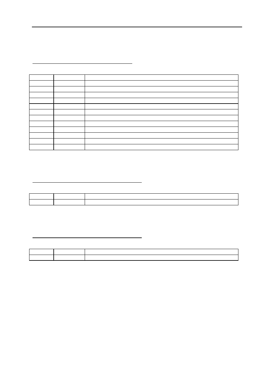
PROTECTION AND SWITCHING UNIT (1337)
location
This unit is located in the engine interconnection unit (in the engine compartment).
Table of fuses
SE2163
L
GPL
G
BVA
GPL
R
I N J E C T
APC
HBT
S T A R T
S T O P
ABS
Fuses and relays
4-10
Allocation of fuses (depending on equipment level)
No. Symbol Amps
Connecti
on
Description
F3 START
STOP
25A (internal)
Fuse: starter motor solenoid (163)
F4
10A internal
Fuse: air conditioning compressor clutch
F5A
15A APCB
Fuse: electric steering column lock (1088)
F5C
R
10A AP11
Fuse: reversing lights (172)
F5D
INJECT
5A AP15
Fuse: injection computer + after ignition feed (120) -
electric steering column lock (1088)
F5E
5A AP44
Fuse: air bag + after ignition feed and electric power
assisted steering (756-1232)
F5F APC
HBT
15A AP43
Fuse:passenger compartment + ignition feed: gear selector
lever display (1129) - shift pattern control switch (129) -
cruise control stop/start control (1081) - driving school
instructor's control unit (469) - passenger compartment
fuse and relay box (260) - additional heater relay 1 (1067) -
additional heater relay 2 (1068) - diagnostic socket (225) -
car phone hands-free microphone (789)
F5H
5A AP4
Fuse: automatic gear box + after ignition feed (119)
F5G
L
GPL
G
10A
not in use
F6
30A (internal)
Fuseheated rear screen (200)
F7A
7.5A LPD
Fuse:right-hand side light (172-226) - cruise control
stop/start control (1081) - ESP stop/start button (1106) -
gear selector lever display (1129) - left-hand heated seat
control (1514) - right-hand heated seat control (1513) - rigid
roof switch (1482) - windscreen simultaneous control (854)
- LPG or petrol selector switch (1003)
Fuses and relays
4-11
F7B
7.5A LPG
Fuse: left-hand side lights (173-227) - cigarette lighter
(101) - hazard warning lights and door locking switch
(1391) - headlight adjustment rheostat switch (1390) - air
conditioning control panel (319) - radio (261) - multifunction
display (653) - UCH (1125) - CD changer (1272) - double
front electric window driver's control (1512) - electric door
mirror control (134) - rear electric window locking control
(135) - double rear window driver's control (1511) -
passenger's electric window control (133) - right-hand rear
electric window control (130) - left-hand rear electric
window control (131)
F8A
10A RPD
Fuse: right-hand main beam headlight (226)
F8B
10A RPG
Fuse: left-hand main beam headlight (227)
F8C
15A CPD
Fuse: right-hand dipped beam headlight (226) - rear height
sensor (1372) - front height sensor (1373) - headlight
adjustment rheostat switch (1390) - right-hand headlight
adjustment motor (538)
F8D
15A CPG
Fuse: left-hand dipped beam headlight (227) - left-hand
headlight adjustment motor (537)
F9
25A (internal)
Fuse: windscreen wiper motor (212)
F10
20A
8F - 8E
Fuseleft- and right-hand front fog lights (176-177)
F11
40A (internal)
Fusecooling fan assembly (188)
F13
ABS
25A BP14
Fuse:ABS computer (118) or Electronic Stability Program
(1094)
F15
20A BP42
Fuse: automatic gearbox + after ignition feed (119)
F16
10A
not in use
Fuses and relays
4-12
PROTECTION AND COMMUTATION UNIT (1337)
location
This unit is located in the engine interconnection unit (in the engine compartment).
1
4
9
12
15
10
5E
P2
CRYSTAL
4
16
5C
1
PPM2
GREY
5G
5H
5F
12
PPA
BLACK
8B
8A
8D
8C
1
5A
7A
7B
11
13
6
3
PEH BLUE
PEM BROWN
PPH1
GREY
PPM1
BLACK
4
5D
12
PPH2
BROWN
P1
BLUE
1
7
1
1
1
7
6
12
12
6
SE2161
Fuses and relays
4-13
Allocation (according to equipment level)
PEH (12-track connector) BLACK
Track Connecti
on
Description
1
AP15
Engine function fuse protected + after ignition feed
2
--
Not in use
3
SP2
+ Protected accessories > Radio
4
32B
Oil -oil level sensor signal 1
5
32A
Oil - oil level sensor signal 2
6
14M
Front wiper park position control > Computer
7
4DN
Anti-lock braking system LOW CAN signal
8
CANL
CAN L fault finding signal
9
3SN
Engine 2 CAN L signal
10
CANH
CAN H fault finding signal
11
4DM
ABS HIGH CAN signal
12
3SM
Engine HIGH CAN signal
Allocation (according to the equipment level)
PPH1 (4-track connector) GREY
Track Connecti
on
Description
1
BP14
+ Protected battery > Anti-lock braking system
2
15LP
Protected rear screen heating + control
3
MAS
Left-hand front side member electronic earth
4
3FB
+ Injection > Protective relay
Allocation (according to the equipment level)
PPH2 (12-track connector) BROWN
Track Connecti
on
Description
1
14L
Front high speed wiper timer + control
2
14K
Low speed windscreen wiper time switch + control
3
NAM
Left-hand upper cross member electronic earth
4
CPD
+ Right-hand protected dipped headlight
5
3N
+ Fuel pump
6
LPG
+ Protected left-hand side light
7
LPD
+ Protected right-hand side light
8
APCB
+ Protected after ignition feed / Lock column fuse contact normally closed
9
H66P
Reverse lights + control
10
AP44
Electric power assisted steering ECU fuse + protected after ignition feed
11
AP43
Protected fuse + after ignition feed
12
--
Not in use

Fuses and relays
4-14
Allocation (according to equipment level)
PPA (12-track connector) BLACK
Track Connecti
on
Description
1
LPG
+ Protected left-hand side light
2
LPD
+ Protected right-hand side light
3
RPG
+ Left-hand protected main beam headlight
4
RPD
+ Right-hand protected main beam headlight
5
CPD
+ Right-hand protected dipped beam headlight
6
CPG
+ Left-hand protected dipped beam headlight
7
8F
+ Right-hand front fog light > Resistor
8
8E
+ Left-hand front fog light > Resistor
9
--
Not in use
10
--
Not in use
11
--
Not in use
12
--
Not in use
Allocation (according to the equipment level)
PEM (12-track connector) BLACK
Track Connecti
on
Description
1
3AC
Fuel pump relay coil - control
2
3AA
Power latch relay coil - control
3
2K
DF terminal alternator charger signal
4
--
Not in use
5
--
Not in use
6
26Z
Automatic gearbox neutral + signal
7
--
Not in use
8
2JD
+ Alternator excitation
9
SP2
+ Protected accessories > Radio
10
32B
Oil - oil level sensor signal 1
11
32A
Oil - oil level sensor signal 2
12
28A
Oil pressure warning light - control
Allocation (according to the equipment level)
PPM1 (4-track connector) BLACK
Track Connecti
on
Description
1
3FB1
+ Injection > Protective relay
2
3FB2
+ Injection > Protective relay
3
D
+ Starting
4
49L / 49B Low speed fan assembly resistor + control or fan assembly + control
Fuses and relays
4-15
Allocation (according to equipment level)
PPM2(12-track connector) GREY
Track Connection
Description
1
BP42
+ Protected battery > automatic gearbox computer
2
--
Not in use
3
BP31
+ Injector fuse protected battery > fuel pump
4
--
Not in use
5
38R
Air conditioning clutch + control
6
AP11
Reversing lights fuse + protected after ignition feed
7
--
Not in use
8
3BS
Ignition coil control
9
H66P
Reverse lights + control
10
AP4
Automatic transmission protected fuse + after ignition feed
11
--
Not in use
12
--
Not in use
Allocation (according to the equipment level)
P1 (1-track connector) BLUE
Track Connection
Description
1
49R
High speed fan assembly feed
Allocation (according to the equipment level)
P2 (1-track connector) CRYSTAL
Track Connection
Description
1
BP31
+ Injector fuse protected battery > fuel pump
Fuses and relays
4-16
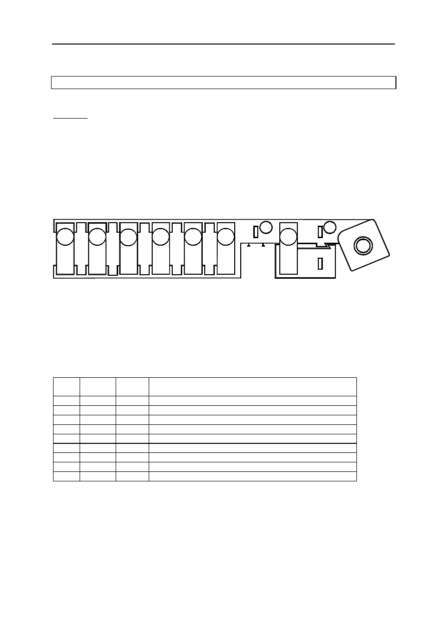
POWER FEED FUSE RACK (777)
Location
This unit is located in the engine interconnection unit, below the Protection and Commutation Unit
(1337).
2
7
9
8
4
6
5
3
S E 2 1 6 5
1
Allocation of fuses (depending on equipment level)
No. Amps
Connec
tion
Description
F1
--
--
not in use
F2
40A BP35
Fuse: preheating unit (257)
F3
--
--
not in use
F4
70A BP12
Fuse: passenger compartment fuse and relay box (260)
F5
50A BP8
Fuse: ABS computer (118 - 1094)
F6
70A BP91
Fuse: additional heater relay 2 (1068)
F7
40A BP9
Fuse: additional heater relay 1 (1067)
F8
60A BP11
Fuse: passenger compartment fuse and relay box (260)
F9
70A BP81
Fuse: electric power-assisted steering system (1232)
Fuses and relays
4-17
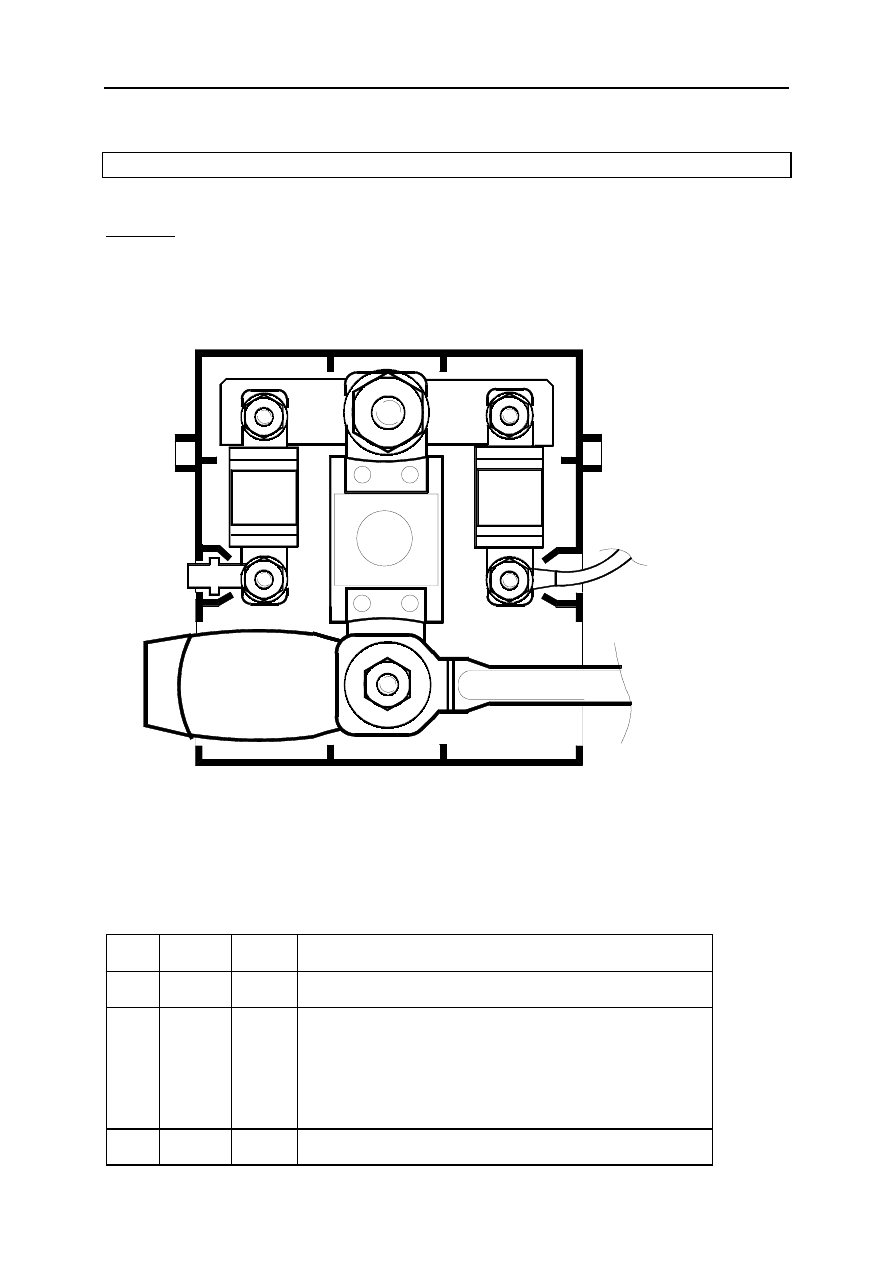
PROTECTED POSITIVE BATTERY UNIT (1033)
Location
This unit is located on the positive battery terminal.
F3
S E 2 1 6 2
F2
F1
Allocation of fuses (depending on equipment level)
No. Amps
Connec
tion
Description
F1
30A BPS1
Fuse: passenger compartment fuse and relay box +
protected battery (260)
F2
350A
400A
BPDA
Fuse: + protected starter battery (163) - alternator (103) -
power feed fuse board (777) - protection and commutation
unit (1337).
Rating:
- 350 Amps for petrol engines.
- 400 Amps for diesel engines.
F3
30A BP31
Fuse: + engine functions protected battery via protection and
commutation unit (1337) - diesel fuel heater relay (450)
Fuses and relays
4-18
RELAY PLATE (450)
Location
This unit is located in the engine interconnection unit, below the Protection and Commutation Unit
(1337).
S E 2 1 6 4
A
B
Allocation of relays (depending on equipment level)
F9Q engine
No. Amps
Description
A 20A
Relay diesel fuel heater (450)
B
--
Not in use
Wyszukiwarka
Podobne podstrony:
konspekt platfus
PLATFUSI
więcej podobnych podstron