We reserve the right to make changes in design or add improvements without incur-
ring the obligation to make such changes in equipment previously manufactured.
PARTS-SERVICE
GRAM
SUBJECT: STEER AXLE SPINDLE ARM STOPS
A steering spindle arm stop has been designed to prevent overstroking of the steering cylinder piston rod.
The stops should be installed if a piston rod bending problem is encountered.
Parts Involved
Part Number
Qty.
Description
15032
2
3/4 UNF Nut
15148
2
3/4 x 1 1/2 UNF cpscw.
Alteration & Adjustment Instructions
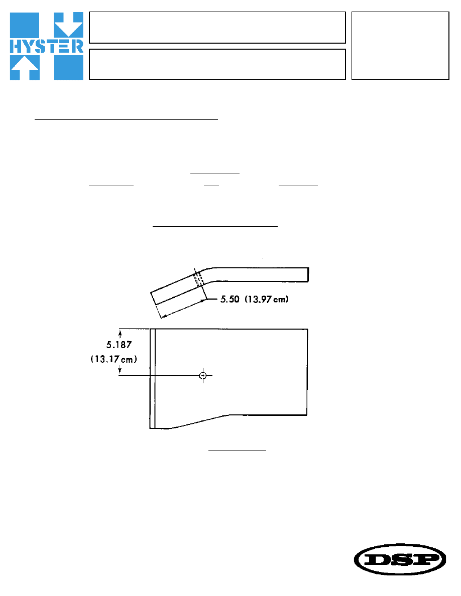
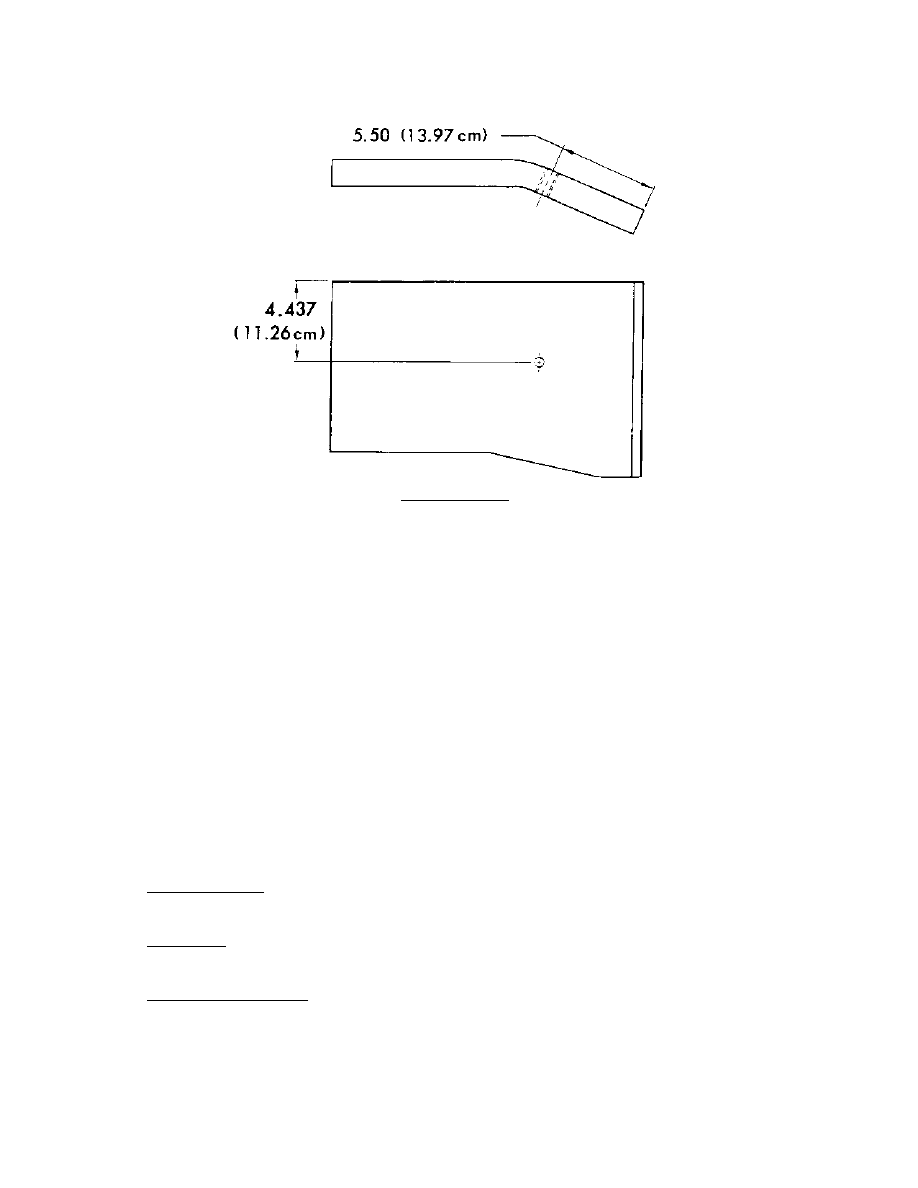
1.) Drill and tap one 3/4 — 16 UNF hole in each steer axle plate weldment at the location shown below.
G-F-71
DATE: April 6, 1978
MODEL: H360-620B
STEERING
continued . . .
Right Hand Plate
G-F-71
Page 2 of 2
Left Hand Plate
2.) Fully thread one jam nut, 18032, on each capscrew, 15148, and install in each plate.
3.) Raise the steer wheels off the ground.
4.) Loosen the piston rod clamp bolt and turn the steering cylinder piston rod in or out to
obtain an equal right and left hand turning radius. The piston rod should be extended
fully in both directions.
Turning the rod out will decrease the left turn radius and increase the right turn
radius.
5.) Turn the steer tires to the extreme right hand turn. Adjust the R.H. stop bolt until the
bolt head contacts the steering spindle arm. Turn the stop bolt out three full turns and
tighten the jam nut.
6.) Repeat step five for the left hand turn.
Interchangeability:
Not affected
Parts Stock:
Not affected
Effective Serial Number:
Not affected
Wyszukiwarka
Podobne podstrony:
p39 071
p02 071
P16 071
04 2005 071 074
p05 071
071
10 2005 069 071
12 2005 071 074
P25 071
p09 071
pf 2015 067 071
P20 071
p34 071
p06 071
2010 03, str 066 071
071
p33 071
P28 071
P17 071
więcej podobnych podstron