UPDATE: 12/98
CD Changer Installation Instructions for:
1999 BMW 5 Series Sedan (E39)
Mounting of CD Changer
In Factory Left-Rear Trunk Area
Part Description
Current E39 Kit P/N
82 11 1 469 911
QTY
New E39 Kit P/N
82 11 1 469 911
QTY
Main CD-C bracket
65 12 8 371 137
1
85 12 8 361 453
1
Main base bracket
65 12 8 361 452
1
65 12 8 361 452
1
M5x14 bolt
07 11 9 915 113
6
07 11 9 915 113
3
Clip nuts
61 13 1 372 033
6
61 13 1 372 033
3
Screw
07 11 9 916 946
1
07 11 9 916 946
1
Cap nut
51 71 1 934 930
2
51 71 1 934 930
2
Nylon insert nut
63 17 1 367 868
1
63 17 1 367 868
1
CD sub bracket
65 12 8 371 136
1
N/A
0
Installation Instruction P/N 99 00 0 001 756
BMW of North America, Inc.
Product & Service Engineering Dept.
December 1998

GENERAL INFORMATION
INTRODUCTION
These installation instructions were produced to give the installation technician all necessary
information to properly install the BMW CD Changer in the left side rear trunk area in all E39 sedan
vehicles.
These instructions were developed by the Product and Service Engineering Department of BMW
of North America, Inc. specifically for BMW vehicles and are not to be compared to any existing
products for vehicles other then BMW.
These instructions were complete and up to date at time of- issue. Any changes in the vehicle or
problems noted by the installer should be reported directly to BMW Product and Service
Engineering Department. Questions regarding this installation should be directed to the BMW
Technical Hotline.
Read all instructions carefully before proceeding with this installation. LH (left hand) and RH (right
hand) are referenced as determined from sitting in the driver's seat facing forward. Instructions
dealing with a common disassembly procedure are referenced to the TIS file found on the DIS
Tester.
REQUIRED TOOLS
Common hand tools
NECESSARY VEHICLE PREPARATION
Step 1
First, access the CD changer location in the left rear cargo area by opening the cosmetic cover
Step 2
Locate the CD changer audio and power/I-Bus cables. Position the cables to avoid pinching them
during the sub bracket installation process
Page 2
PREINSTALLATION
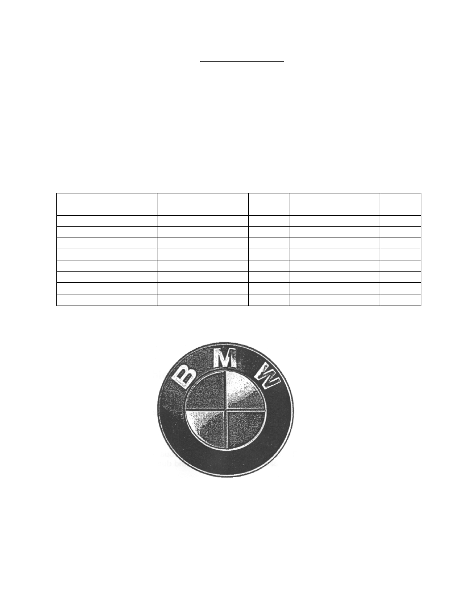
All vehicles with factory pre-wiring should have
the CD audio cable inserted into the (17 pin)
Radio Connector. Before starting installation of
the CD changer, check that the CD audio
cable is secured in place with the Lock Pin
(see Figure 1)
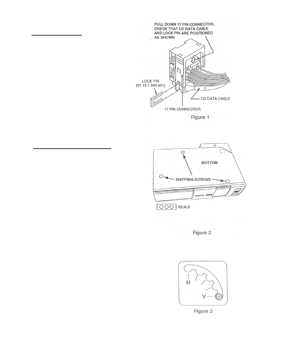
CD CHANGER PREPARATION
Shipping screws are installed on the bottom of
the CD changer to protect the unit during
shipment. Prior to installation, make sure you
remove the shipping screws and cover the
holes with the supplied adhesive seals as
described below.
1. Remove the 3 shipping screws from the
bottom of the CD changer (see Figure 2).
Store the 3 screws for future use; replace
3 screws only if a unit needs to be
returned for an exchange.
2. Cover the holes where the shipping screws
were installed with the 3 adhesive seals
supplied with the unit. (see Figure 2)
3. Change the position of the horizontal /
vertical Spring Pin on both sides of the CD
changer to the Vertical (h position (see
Figure 3). (The unit is shipped with the
Spring Pin in the Horizontal position.)
Page 3
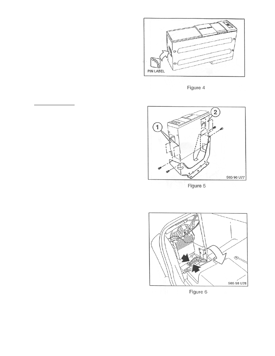
4. To protect the Spring Pin, cover the Pin
area with the supplied Pin Label by
aligning the two diagonally opposite
holes with H and V positions (see
Figure 4).
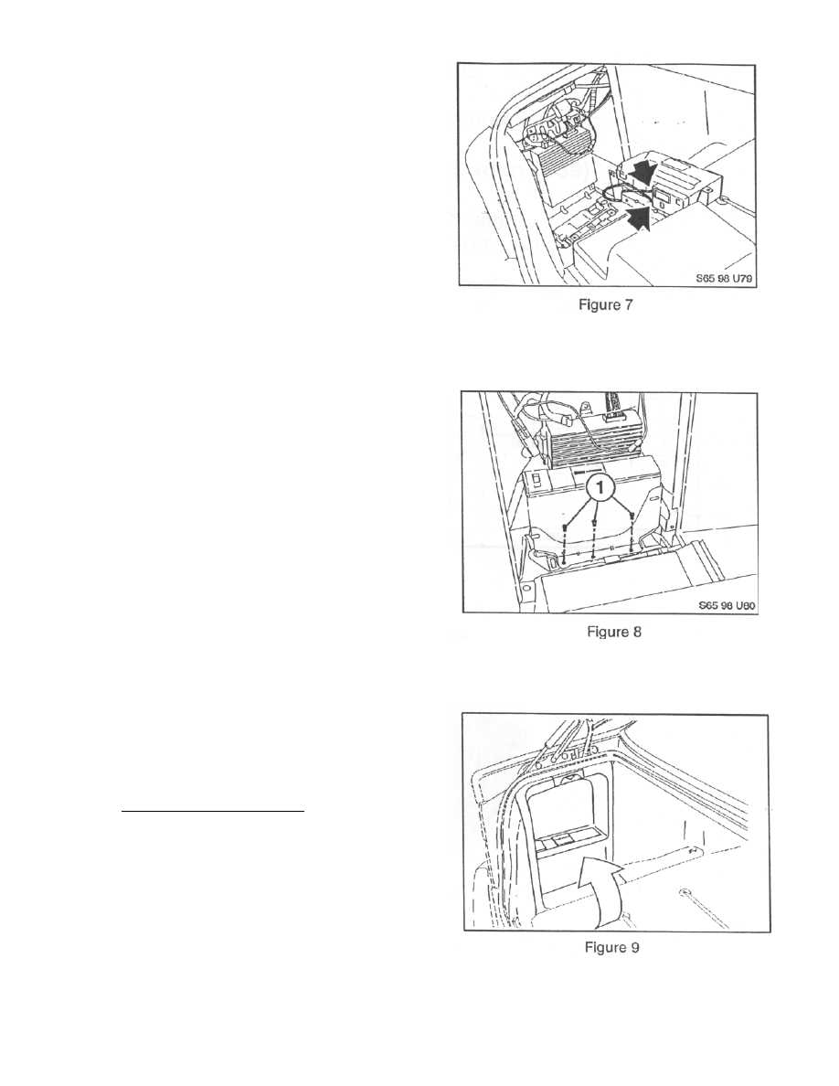
INSTALLATION
5. Attach the mounting bracket to the CD
Changer using the mounting hardware
(M4) shipped with the CD Changer. Use
lower mounting holes for Left side and
higher ones for right side (see Figure 5).
7. Locate the CD Audio Cable (6-pin) and
Power/I-Bus Cable (3-pin), which are
terminated behind CD changer Trunk
Trim Cover in the left side (driver's side)
of the trunk (see Figure 6).
Page 4
8. Connect CD audio and Power/I-Bus
cables to CD changer (see Figure 7).
9. First, install a M5 bolt to front
threaded body nut loosely. Then,
install 4 other bolts to remaining 4
body nuts (see Figure 8).
10. Remove tray pocket from CD changer
Trunk Trim Cover and place CD changer
trunk trim bezel over CD changer (See
Figure 9).
FINAL INSTALLATION
11 Inspect all cable/wire routings and
secure with tie-wraps where necessary.
12 Test/operate per Owner's Manual.
13 Replace all interior components.
Page 5
Wyszukiwarka
Podobne podstrony:
bmw E39 E46 E53 nie dziala dmuchawa
Instalacja modułu Bluetooth w BMW E39
TEST KONSOLI ZEGARA, BMW E39 PDFy
Lusterko wsteczne z kompasem do BMW E39
Komputer pokładowy instalacja w BMW E39
bmw E39 samoczynne dizalanie centralnego zamka
Akcesoria multimedialne do BMW E39(1)
bmw E39 brak mocy w modelach do 01 11 02
Złącze AUX w BMW E39(1)
BMW E39 Wymiana wężyków spryskiwaczy
bmw E39 E53 nie dziala dmuchawa
Instalacja radioodtwarzaczainstalacja radioodtwarzacza ze zmieniaczem CD
bmw E39 cieple powietrze na nogi z klimatyzacji
bmw E39 E46 E53 nie dziala dmuchawa
Instalacja modułu Bluetooth w BMW E39
TEST KONSOLI ZEGARA, BMW E39 PDFy
BMW e39 Demontaż reflektora
więcej podobnych podstron