1
Paraboloid Dish
for Stirling Engine
Prof. Shireesh B. Kedare
Adjunct Associate Professor
Department of Energy Science and Engineering
IIT-Bombay
sbkedare@iitb.ac.in
sbkedare@gmail.com
2
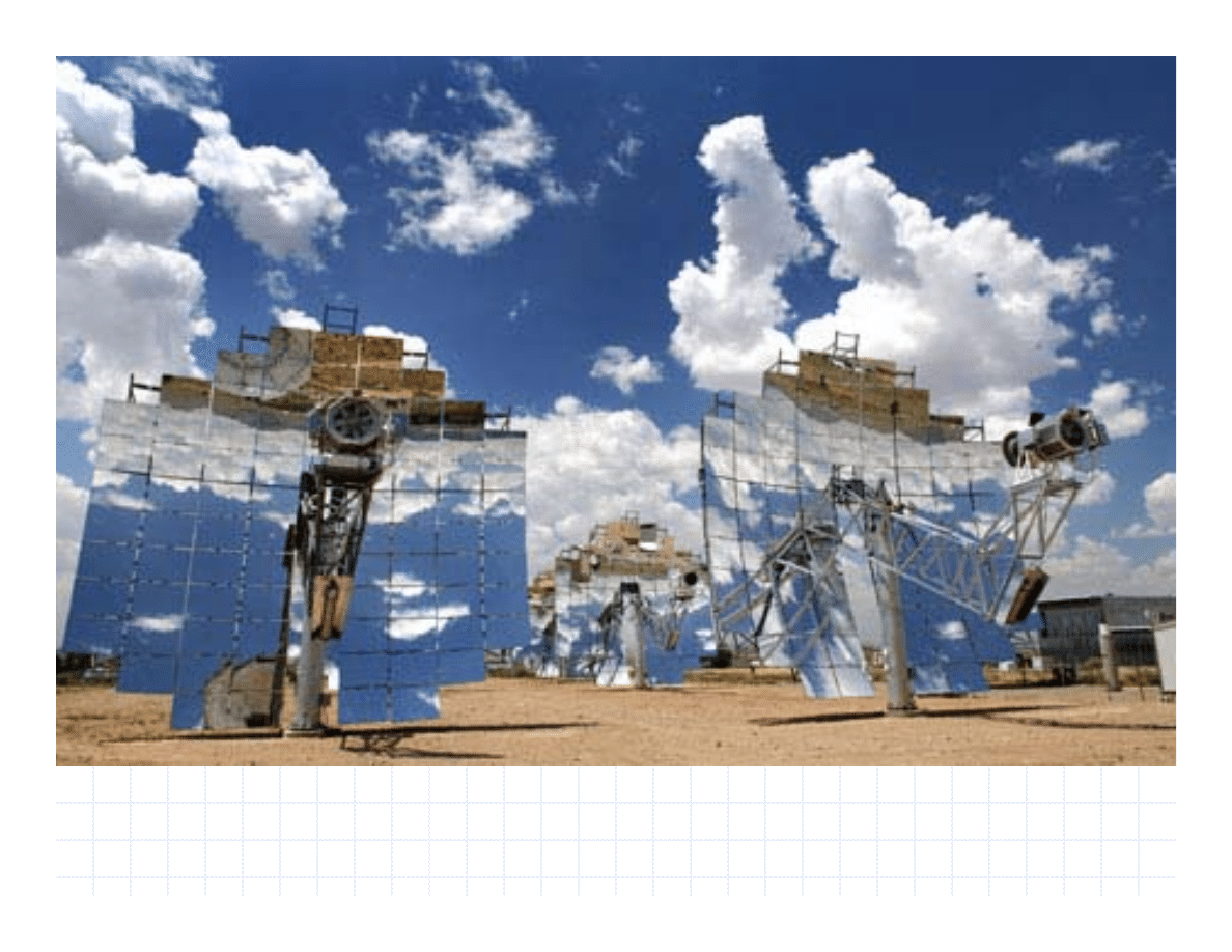
Paraboloid Dishes with Stirling
Paraboloid Dishes with Stirling
Engine at Point Focus
Engine at Point Focus
100 m
2
Dishes with Stirling Engine by SES for
500 & 800 MW plants at Mojave Dessert, US
3
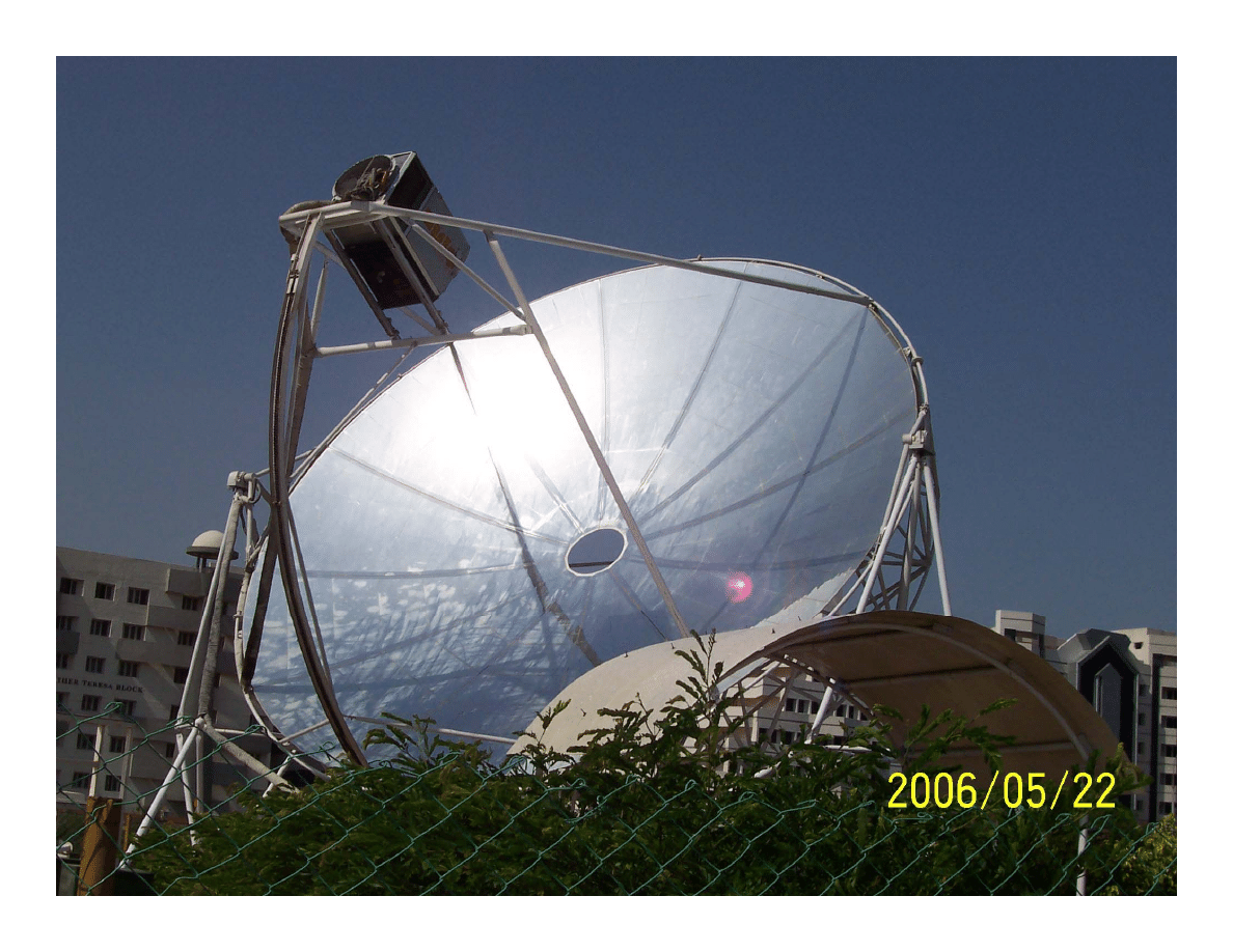
Paraboloid Dish with Point Focus
Paraboloid Dish with Point Focus
56 m
2
Dish with Stirling Engine at VIT,
INDIA
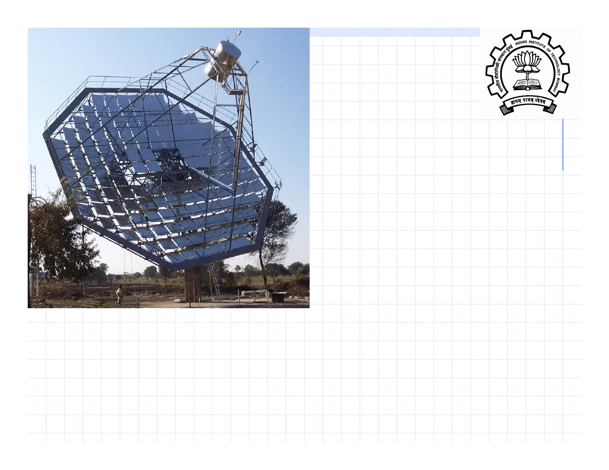
4
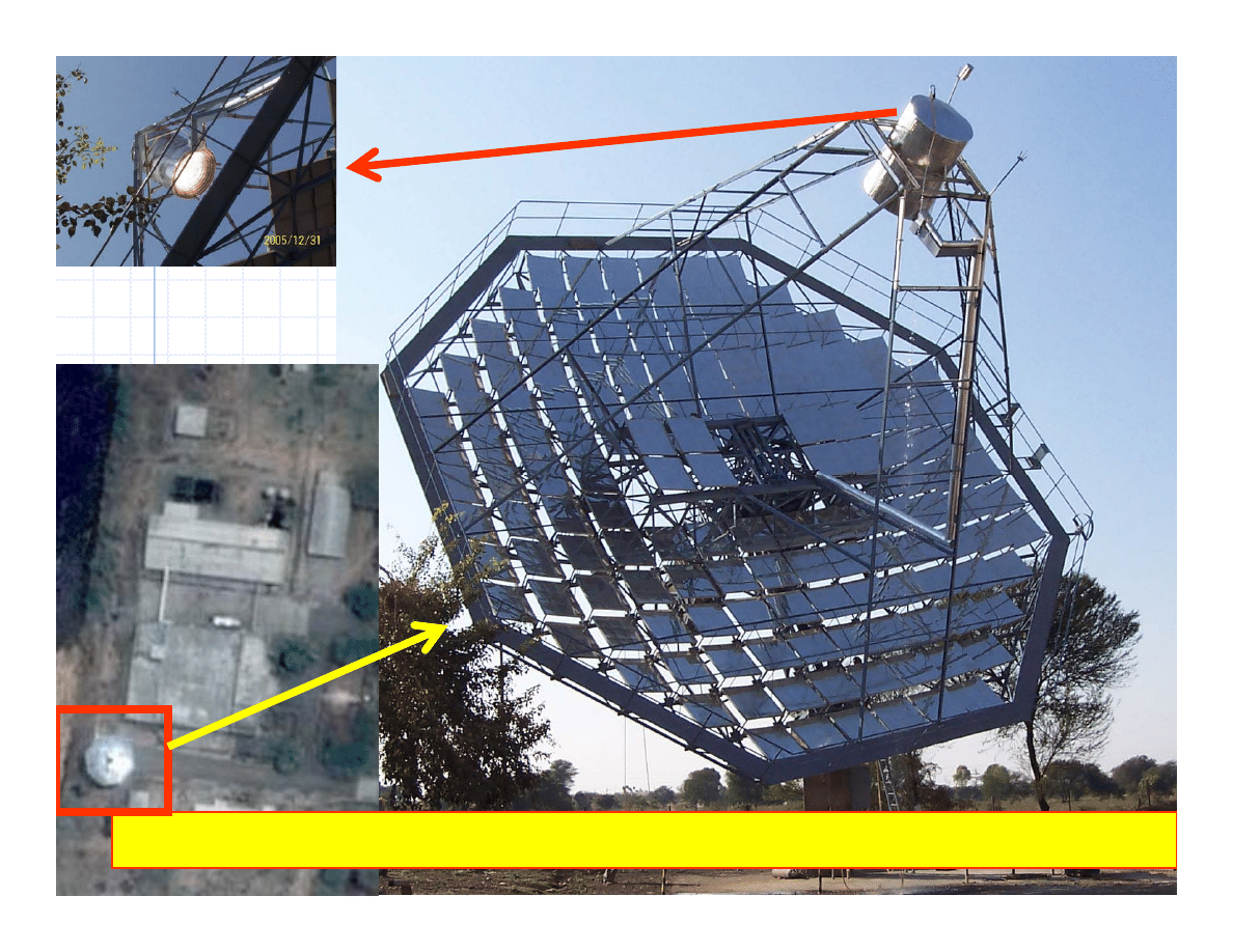
Arun at Mahanand Dairy,
Latur, India
η
= 0.75 – {0.4 + 2.4x10⁻⁵ (Tm - Tamb) + 0.9x10⁻³ (sin θz) } (Tm - Tamb) /Ibn
5
Large Solar Concentrator
Large Solar Concentrator
with Stirling Engine :
with Stirling Engine :
The indigenous design
The indigenous design
ARUN
can be fitted
with Stirling engine
to
supply electrical power.
Stirling engine will have to be imported
presently or indigenous development required.
The power generated may require
50% to 70%
of
the capital investment compared to
Solar
Photo-Voltaic
installations and may work with
capacity factor of
150 to 200%
.
Solar farm for power generation is feasible.
6
Issues related to R and D
Matching the dish with stirling engine for optimum
operating temperature
Efficiency of dish decreases with temperature
Efficiency of engine increases with temperature
Dish can be improved for achieving higher temperature
Improved optical efficiency
Reduced loss coefficient
Increased concentration ratio
Design of solar receiver integrated with stirling engine
Material limits for higher temperature
7
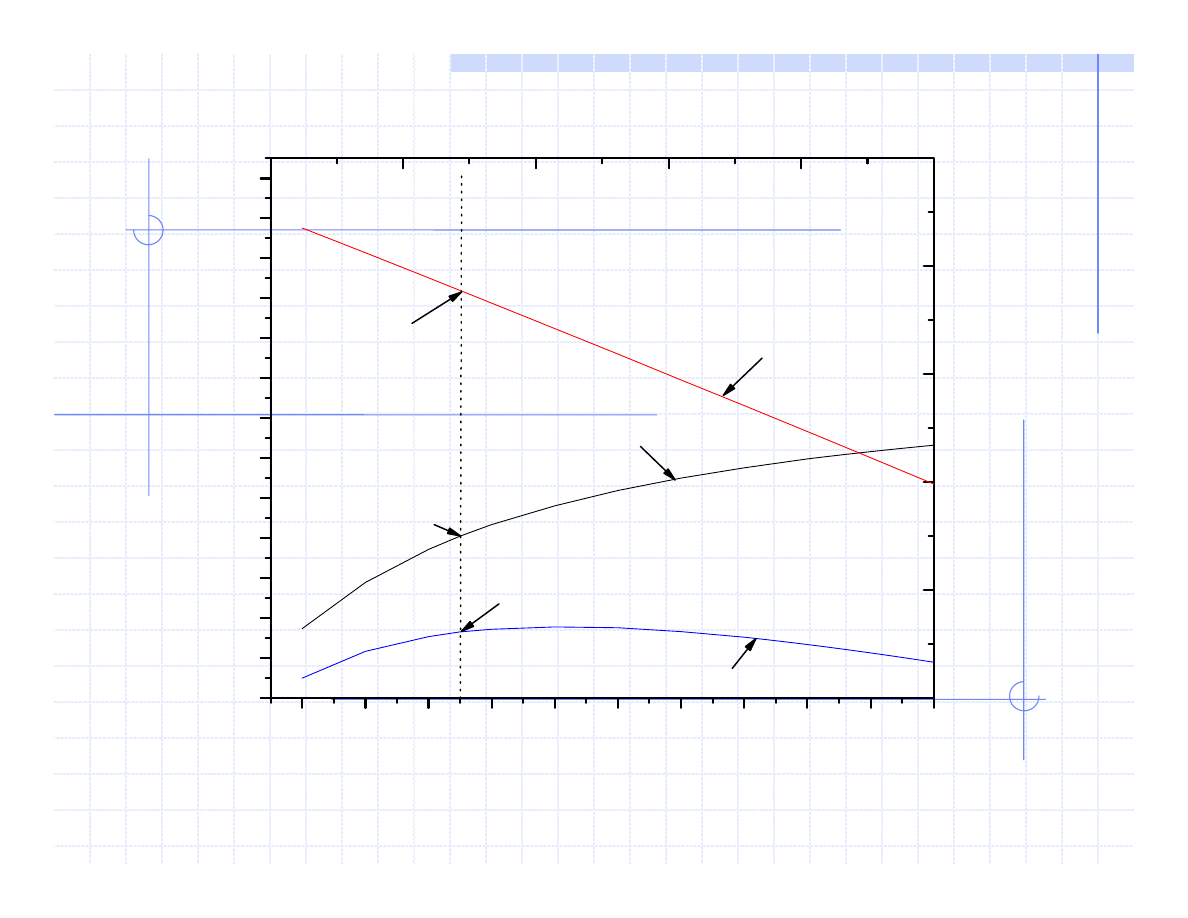
Matching the dish with stirling engine: Optimum temperature
500
600
700
800
900
1000 1100 1200 1300 1400 1500
0.15
0.20
0.25
0.30
0.35
0.40
0.45
0.50
0.55
0.60
0.65
0.70
0.75
0.80
750, 0.659
750, 0.23
750,0.35
η
= 0.8 - { 0.4 + 2.4 x 10
-5
(T
m
- T
amb
)} X
where, X = (T
m
-T
amb
) / I
bn
E
ff
icienc
y,
%
Operating temperature, K
Concentrator efficeiency
Engine efficiency
Overall efficiency
T
amb
= 300 K
I
bn
= 650 W/m
2
8
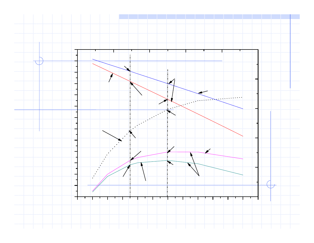
400
500
600
700
800
900 1000 1100 1200 1300 1400 1500 1600
15
20
25
30
35
40
45
50
55
60
65
70
75
80
η
= 0.8 - { 0.4 + 2.4 x 10
-5
(T
m
- T
amb
)} X
where, X = (T
m
-T
amb
) / I
bn
58.01
64.95
31.1
34.82
29.13
31.0816
53.61
44.15
65.97
70.4
Ef
ficiency,
%
Operating temperature, K
Stirling
Engine efficiency
Overall efficiency
I
bn
= 650 W/m
2
I
bn
= 950 W/m
2
I
bn
= 650 W/m
2
Concentrator efficiency
I
bn
= 950 W/m
2
T
amb
= 300 K
Matching the dish with stirling engine: Optimum temperature
9
ARUN160 fitted with Stirling engine
25 kW
elect
Electrical Power
2500
(6-9 h/d; 300-340 d/yr)
Operating hours
60,000-75,000 Units /
year
Annual Electricity
generated, kWh
169 m
2
Ap. Area
ARUN160
Large Solar Concentrator
Large Solar Concentrator
ARUN
ARUN
with Stirling Engine
with Stirling Engine
10
Thanks
Department of Energy Science & Engineering
Indian Institute of Technology Bombay
Prof. Shireesh B. Kedare
sbkedare@iitb.ac.in
sbkedare@gmail.com
Wyszukiwarka
Podobne podstrony:
PORÓWNYWANIE TECHNOLOGII
19 Mikroinżynieria przestrzenna procesy technologiczne,
Technologia informacji i komunikacji w nowoczesnej szkole
Technologia spawania stali wysokostopowych 97 2003
SII 17 Technologie mobilne
W WO 2013 technologia
TECHNOLOGIA PŁYNNYCH POSTACI LEKU Zawiesiny
technologia prefabrykowana
Technology & Iventions
Technologia Maszyn CAD CAM
1 Infrastruktura, technika i technologia procesów logistyczid 8534 ppt
TECHNOLOGIE INFORMATYCZNE CRM
Fermentacyjne technologie zagospodarowanie odpadów
Technologia Informacyjna w moim życiu
więcej podobnych podstron