
Junos for Security Platforms
1
Lab 1
Zones & Security Policies
Overview
In first part of this lab, you will configure a baseline network for your POD, including interface addressing,
routing, and assigning interfaces to zones. The second part of this lab
you will implement security policies
designed
to
allow
only
necessary
traffic
between
zones
within
your
POD.
You
will
configure
custom
applications
and
monitor
the
effects
of
your
changes.
All devices are connected to a common management network which facilitates access to the CLI. These
exercises assume you already have some basic understanding of the JUNOS CLI interfaces and you have
attended the IJS and JRE training.
Note that your lab login (password given to you separately) grants you all permissions needed to
complete this lab; however, some restrictions have been made to prevent loss of connectivity to the
devices. Please be careful, and have fun!
By completing this lab, you will perform the following tasks:
•
Use the Junos operating system CLI to setup a baseline network.
•
Implement routing so that all networks are reachable.
•
Assign interfaces to security zones.
•
Define zone address books necessary for security policy.
•
Implement security policies between zones within your assigned pod.
•
Monitor the effects of your configuration
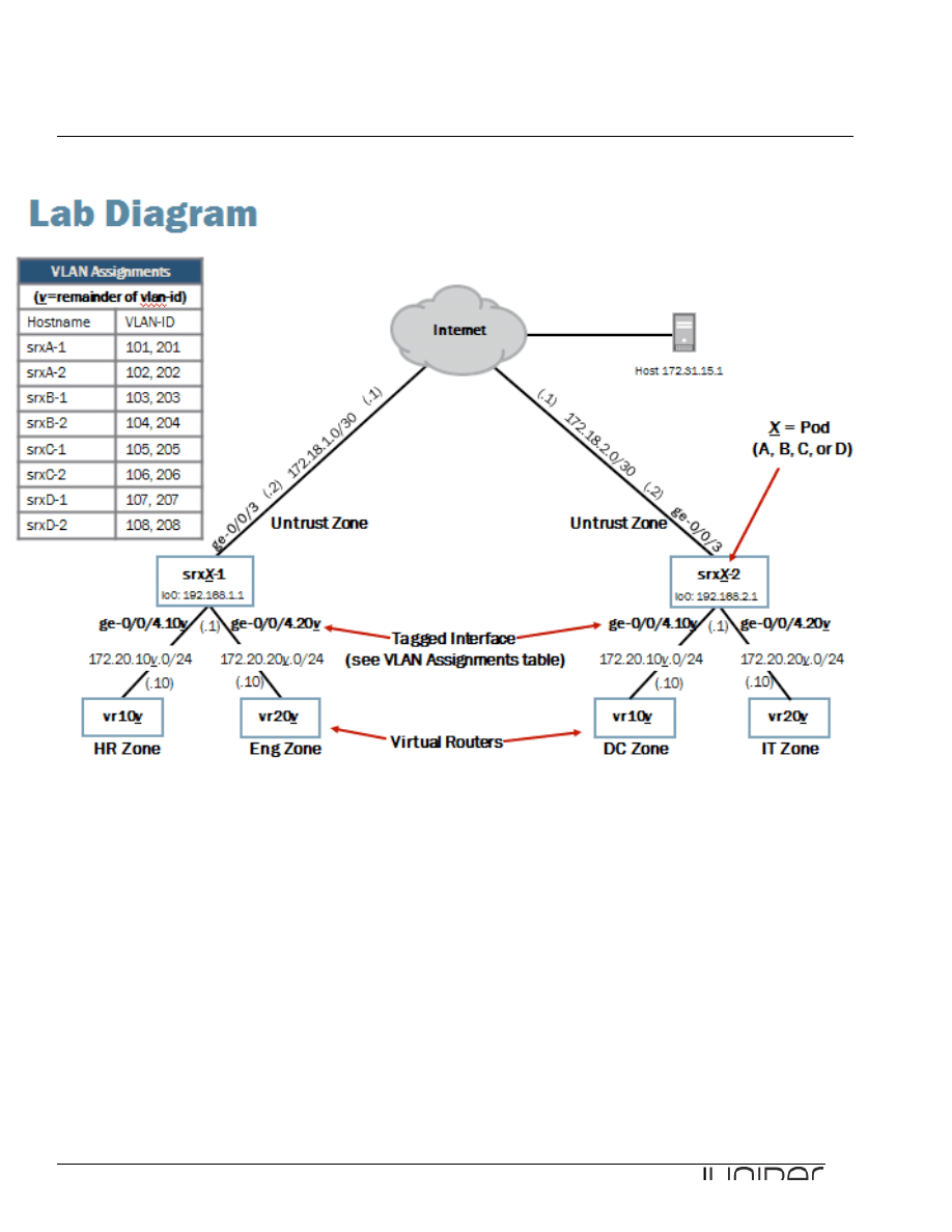
Please refer to the next page lab diagram to perform this exercise:
Junos for Security Platforms
2
Lab Diagram

Junos for Security Platforms
3
Key Commands
Key operational mode commands used in this lab include the following:
show security zones
show interfaces extensive
show security policies
show security flow session
Part 1: Logging In
Using the CLI
In this lab part, you will become familiar with the access details used to access the lab
equipment. Once you are familiar with the access details, you will use the CLI to log in
to your team’s designated station.
____________________________ Note 1 ________________________
Please do NOT delete interface ge-0/0/0 as this is your management interface which
provides access to your CLI session !!
Do NOT delete either the security section of your configurations. This allows your
system to allow any traffic in/out.
_________________________________________________________________
____________________________ Note 2 ________________________
If any time during this lab your access through the management network is lost use the
console connection to access your assigned station. Using the console connection
ensures persistent connectivity even when the management network access is
unavailable. If needed, review the instructions about how to connect to your system
using the console port.
WHEN EXITING FROM THE CONSOLE CONNECTION PLEASE TERMINATE THE
CONNECTION AT THE LOGIN PROMT WITH:
login: CTRL + ^ (where ^ is SHIFT +
in your keyboard)
followed by quit at the telnet prompt
telnet> quit.
_________________________________________________________________
____________________________ Note 3 ________________________
Remember that the exercise proposed in this documentation is generic and the
examples given here apply only to one particular pod of devices. Please adapt the
example to your assigned set of devices (host1-a & host2-a, or host1-b & host2-b, or
host1-c & host2-c, or host1-d & host2-d).
Look at you lab diagram and mind the pod of systems that you have been assigned!
_________________________________________________________________

Junos for Security Platforms
4
Step 1.1
Log in to your system with the username lab using the password given to you. Please use the console
connection to access your system.
At the CLI prompt, enter ?. Your station should have a host name assigned.
[timo@js2 ~]$ telnet SRX2-d
Trying 10.210.14.138...
Connected to SRX2-d.lab2.cavellgroup.com (10.210.14.138).
Escape character is '^]'.
host2-d (ttyp0)
login: lab
Password:
--- JUNOS 10.1R2.8 built 2010-05-11 05:02:14 UTC
lab@host2-d>
Part 2: Configuring the Baseline Network
In this lab part, you will configure the baseline network, including network interfaces and routing.
Step 2.1
View the current configuration of your assigned station.
lab@host2-d> show configuration | no-more
## Last commit: 2011-01-31 23:03:25 UTC by instructor
version 10.1R2.8;
system {
host-name host2-d;
root-authentication {
encrypted-password "$1$KI99zGk6$MbYFuBbpLffu9tn2.sI7l1"; ## SECRET-DATA
ssh-dsa "ssh-dss
AAAAB3NzaC1kc3MAAACBAMQrfP2bZyBXJ6PC7XXZ+MzErI8Jl6jah5L4/O8BsfP2hC7EvRfNoX7MqbrtCX/9gU
H9gChVuBCB+ERULMdgRvM5uGhC/gs4UX+4dBbfBgKYYwgmisM8EoT25m7qI8ybpl2YZvHNznvO8h7kr4kpYuQE
pKvgsTdH/Jle4Uqnjv7DAAAAFQDZaqA6QAgbW3O/zveaLCIDj6p0dwAAAIB1iL+krWrXiD8NPpY+w4dWXEqaV3
bnobzPC4eyxQKBUCOr80Q5YBlWXVBHx9elwBWZwj0SF4hLKHznExnLerVsMuTMA846RbQmSz62vM6kGM13HFon
WeQvWia0TDr78+rOEgWF2KHBSIxL51lmIDW8Gql9hJfD/Dr/NKP97w3L0wAAAIEAr3FkWU8XbYytQYEKxsIN9P
1UQ1ERXB3G40YwqFO484SlyKyYCfaz+yNsaAJu2C8UebDIR3GieyNcOAKf3inCG8jQwjLvZskuZwrvlsz/xtcx
SoAh9axJcdUfSJYMW/g+mD26JK1Cliw5rwp2nH9kUrJxeI7IReDp4egNkM4i15o=
configurator@server1.he"; ## SECRET-DATA
}
login {
user lab {
uid 2000;
class super-user;
authentication {
encrypted-password "$1$mKkMA9pa$AUZPO2UJ9rWwOfp4Kb2/a1"; ## SECRET-
DATA
}

Junos for Security Platforms
5
}
}
services {
ssh;
telnet;
}
syslog {
user * {
any emergency;
}
file messages {
any any;
authorization info;
}
file interactive-commands {
interactive-commands any;
}
}
}
interfaces {
ge-0/0/0 {
description "MGMT Interface - DO NOT DELETE";
unit 0 {
family inet {
address 10.210.14.138/27;
}
}
}
}
security {
zones {
security-zone trust {
interfaces {
all {
host-inbound-traffic {
system-services {
all;
}
protocols {
all;
}
}
}
}
}
}
policies {
default-policy {
permit-all;
}
}
}

Junos for Security Platforms
6
Question: Are any security zones currently configured on your assigned device?
Answer: As shown in the output, security-zone trust currently exists in the configuration.
Question: Why is this security zone configured in the device?
Answer: It is part of the Branch Office Junos Security Device default configuration.
Step 2.2
Let us now change the current flow based security device configuration to a packet based router
configuration. For that you need to delete the security zones and security policy configuration.
Enter configuration mode and issue following commands.
lab@host2-d> configure
Entering configuration mode
[edit]
lab@host2-d# delete security zones
[edit]
lab@host2-d# delete security policies
Step 2.3
Now, configure the packet mode. Your configuration should look like this when finished:
[edit]
lab@host2-d# show security
forwarding-options {
family {
mpls {
mode packet-based;
}
}
}

Junos for Security Platforms
7
Question: How does the packet mode configuration affect the device’s packet forwarding?
Answer: It
disables the flow-‐based security feature of Junos and allows you to run the device as a
normal router.
Step 2.3
Enter configuration mode and navigate to the [edit interfaces] hierarchy. Configure the IP address
for the ge-0/0/3 interface. Refer to the lab diagram for the appropriate IP address.
Note that the third octet of the IP address should also match the unit number of the device in your
POD.
[edit interfaces]
lab@host2-d# set ge-0/0/3 unit 0 family inet address 172.18.x.2/30
Step 2.4
Configure the lo0 loopback interface IP address. Refer to the lab diagram for the IP address assigned to
your device.
Note that the third octet of the IP address should also match the unit number of the device in your
POD.
[edit interfaces]
lab@host2-d# set lo0 unit 0 family inet address 192.168.x.1/32
Step 2.5
Configure the ge-0/0/4 interface. Enable VLAN-tagging and configure two logical units. Each logical unit
number should match its associated VLAN-ID. Refer to the VLAN assignments table listed on the network
diagram. Assign the IP address shown on the lab diagram.
Note that the third octet of the IP address should also match the logical unit’s associated VLAN-ID.
VLAN-ID can be found in the VLAN assignment table in the Lab diagram.
[edit interfaces]
lab@host2-d# set ge-0/0/4 vlan-tagging
[edit interfaces]
lab@host2-d# set ge-0/0/4 unit 10v vlan-id 10v
[edit interfaces]
lab@host2-d# set ge-0/0/4 unit 10v family inet address 172.20.10v.1/24
[edit interfaces]
lab@host2-d# set ge-0/0/4 unit 20v vlan-id 20v

Junos for Security Platforms
8
[edit interfaces]
lab@host2-d# set ge-0/0/4 unit 20v family inet address 172.20.20v.1/24
Question: Which VLAN-IDs are associated with your assigned device?
Answer: The answer varies. The VLAN-IDs associated with srxB-1 are 108 and 208.
Step 2.6
Configure a static default route that points to the IP address associated with the remote end of the ge-0/0/3
interface for your device (the Internet cloud). Commit the configuration and return to operational mode.
[edit interfaces]
lab@srxB-1# up
[edit]
lab@srxB-1# edit routing-options
[edit routing-options]
lab@srxB-1# set static route 0/0 next-hop 172.18.x.1
[edit routing-options]
lab@srxB-1# commit and-quit
commit complete
Exiting configuration mode
lab@srxB-1>
Step 2.7
Configure the other device in your POD in similar way repeating steps 2.2 - 2.6.

Junos for Security Platforms
9
Part 3: Verifying Network Connectivity
In this lab part, you will verify network connectivity within your pod.
Step 3.1
Check the status of your configured interfaces using the show interfaces terse command.
lab@host2-d> show interfaces terse | no-more
Interface Admin Link Proto Local Remote
ge-0/0/0 up up
ge-0/0/0.0 up up inet 10.210.14.138/27
gr-0/0/0 up up
ip-0/0/0 up up
lsq-0/0/0 up up
lt-0/0/0 up up
mt-0/0/0 up up
pd-0/0/0 up up
pe-0/0/0 up up
ge-0/0/1 up up
ge-0/0/2 up up
ge-0/0/3 up up
ge-0/0/3.0 up up inet 172.18.2.2/30
ge-0/0/4 up up
ge-0/0/4.108 up up inet 172.20.108.1/24
ge-0/0/4.208 up up inet 172.20.208.1/24
ge-0/0/4.32767 up up
ge-0/0/5 up down
ge-0/0/6 up down
ge-0/0/7 up down
ge-0/0/8 up down
ge-0/0/9 up down
ge-0/0/10 up down
ge-0/0/11 up down
ge-0/0/12 up down
ge-0/0/13 up down
ge-0/0/14 up down
ge-0/0/15 up down
fxp2 up up
fxp2.0 up up tnp 0x1
gre up up
ipip up up
lo0 up up
lo0.0 up up inet 192.168.2.1 --> 0/0
lo0.16384 up up inet 127.0.0.1 --> 0/0
lo0.16385 up up inet 10.0.0.1 --> 0/0
10.0.0.16 --> 0/0
128.0.0.1 --> 0/0
128.0.1.16 --> 0/0
inet6 fe80::226:880f:fce9:dc80
lo0.32768 up up
lsi up up
mtun up up

Junos for Security Platforms
10
pimd up up
pime up up
pp0 up up
st0 up up
tap up up
vlan up up
Question: What is the administrative status and link status of your configured interfaces?
Answer: As shown in the output taken from srx2-D, the administrative status and link status of
the configured interfaces should all indicate a status of up.
Question: What is the status of your management interface? (Refer to the management network
diagram as needed.)
Answer: The management interface is ge-0/0/0.0 and should also indicate an administrative
status and link status of up.
Step 3.2
Verify reachability to the remote peer in your pod across the Internet using the ping command.
lab@host1-d> ping 172.18.2.2 rapid count 5
PING 172.18.2.2 (172.18.2.2): 56 data bytes
!!!!!
--- 172.18.2.2 ping statistics ---
5 packets transmitted, 5 packets received, 0% packet loss
round-trip min/avg/max/stddev = 1.460/2.573/6.604/2.018 ms
Question: Was the ping to your remote peer successful?
Answer: As indicated by the output from srxB-1, the ping should be successful. If the ping is not
successful, double-check your configuration.

Junos for Security Platforms
11
_____________________________ Note _________________________
The next lab steps require you to log in to the virtual router attached to your team’s
device. The virtual routers are logical devices created on a J Series Services Router.
Refer to the management network diagram for the IP address of the vr-device.
Although you have two virtual routers attached to your student device, you only need to
establish a single session.
_________________________________________________________________
Step 3.3
Open
a
separate
Telnet
session
to
the
virtual
router
attached
to
your
team
device.
You
need
to
open
a
new
ssh
session
to
the
Jump
Server
and
from
there
establish
a
telnet
session
to
the
virtual
device.
Observe
that
you
have
only
very
limited
access
to
the
virtual
device
and
should
follow
the
lab
instructions
as
written
very
strictly.
Use the login credentials from the table here below.
Virtual Router Login Details
Student Device
User Name
Password
srxA-‐1
a1
lab123
srxA-‐2
a2
lab123
srxB-‐1
b1
lab123
srxB-‐2
b2
lab123
srxC-‐1
c1
lab123
srxC-‐2
c2
lab123
srxD-‐1
d1
lab123
srxD-‐2
d2
lab123
[timo@js2 ~]$ telnet 10.210.14.139
Trying 10.210.14.139...
Connected to j2350.lab2.cavellgroup.com (10.210.14.139).
Escape character is '^]'.
vr-device (ttyp0)
login: d1
Password:
--- JUNOS 9.2R1.10 built 2008-08-07 06:45:07 UTC
NOTE: This router is divided into many virtual routers used by different teams.
Please only configure your own virtual router.
You must use 'configure private' to configure this router.
d1@vr-device>

Junos for Security Platforms
12
Step 3.4
Verify reachability to the remote virtual routers connected to the device of your peers using the ping
command. Be sure to source your ping from the correct virtual-router routing-instance.
_____________________________ Note _________________________
Keep in mind that when working with virtual routers and routing instances, command
syntax is different. If needed, please reference the detailed lab guide for sample
command syntax for the individual verification tasks performed within this lab.
________________________________________________________________
d1@vr-device> ping 172.20.107.10 routing-instance vr108 rapid count 5
PING 172.20.107.10 (172.20.107.10): 56 data bytes
!!!!!
--- 172.20.107.10 ping statistics ---
5 packets transmitted, 5 packets received, 0% packet loss
round-trip min/avg/max/stddev = 3.872/5.390/6.554/0.956 ms
d1@vr-device> ping 172.20.107.10 routing-instance vr208 rapid count 5
PING 172.20.107.10 (172.20.107.10): 56 data bytes
!!!!!
--- 172.20.107.10 ping statistics ---
5 packets transmitted, 5 packets received, 0% packet loss
round-trip min/avg/max/stddev = 3.915/5.124/6.059/0.791 ms
d1@vr-device> ping 172.20.207.10 routing-instance vr108 rapid count 5
PING 172.20.207.10 (172.20.207.10): 56 data bytes
!!!!!
--- 172.20.207.10 ping statistics ---
5 packets transmitted, 5 packets received, 0% packet loss
round-trip min/avg/max/stddev = 3.982/4.736/5.700/0.702 ms
d1@vr-device> ping 172.20.207.10 routing-instance vr208 rapid count 5
PING 172.20.207.10 (172.20.207.10): 56 data bytes
!!!!!
--- 172.20.207.10 ping statistics ---
5 packets transmitted, 5 packets received, 0% packet loss
round-trip min/avg/max/stddev = 3.783/4.569/6.132/0.922 ms
d1@vr-device>
Question: Were the pings between remote virtual-routers successful?
Answer: As indicated by the output from user b1, the pings should be successful. If the pings
are not successful, double-check your configuration and notify your instructor.

Junos for Security Platforms
13
Part 4: Configuring Zones
In this lab part, you will remove the current zone configuration and reassign your device interfaces to
various security and functional zones.
Step 4.1
Return to the terminal session opened to your assigned device. Enter configuration mode and navigate to
the [edit security] configuration hierarchy.
[edit]
lab@host1-d# edit security
[edit security]
lab@host1-d# show
forwarding-options {
family {
mpls {
mode packet-based;
}
}
}
Question: Which configured security zones are on your assigned device and which interfaces
are associated with the configured security zones?
Answer: As indicated by the output from srxB-1, currently no security zones are configured.
Question: Which configured functional zones are on your assigned device and which interfaces
are associated with the configured functional zones?
Answer: As indicated by the output from srxB-1, the configuration has no functional zones.

Junos for Security Platforms
14
Question: Should a user be able to telnet to your assigned device? Why or why not?
Answer: The configuration allows telnet to each device. No policies exist that deny traffic, and
telnet is also enabled under the [edit system services] hierarchy.
Step 4.2
Delete the current security policy. You will create a new policy in the next few steps.
[edit security]
lab@host1-d# delete
Delete everything under this level? [yes,no] (no) yes
[edit security]
lab@host1-d# show
[edit security]
lab@host1-d#
Step 4.3
Refer to the lab diagram and configure the untrust, hr (human resources), eng (engineering), dc
(data center), and it (information technology) zones. Configure these zones as security zones. Add the
appropriate network interfaces under each security zone. Be sure to configure only the security zones
associated with your assigned device. Note that we took the following sample captures from srxB-1 and
srxB-2. You should configure only the security zones associated with your designated student device.
[edit security]
lab@host1-d# set zones security-zone hr interfaces ge-0/0/4.107
[edit security]
lab@host1-d# set zones security-zone eng interfaces ge-0/0/4.207
[edit security]
lab@host1-d# set zones security-zone untrust interfaces ge-0/0/3.0
[edit security]
lab@host2-d# set zones security-zone dc interfaces ge-0/0/4.108
[edit security]
lab@host2-d# set zones security-zone it interfaces ge-0/0/4.208
[edit security]
lab@host2-d# set zones security-zone untrust interfaces ge-0/0/3.0

Junos for Security Platforms
15
Step 4.4
Next, configure a functional zone and associate it with your device’s management interface.
[edit security]
lab@host1-d# set zones functional-zone management interfaces ge-0/0/0.0
Question: What name did you assign to the functional zone of your device? Why?
Answer: Each student should assign a functional zone name of management. As shown in the
output, the Junos OS predefines this name. management is the only name the Junos OS
allows for a functional zone.
Step 4.5
Configure the functional zone so that it allows SSH, telnet, ping, traceroute, HTTP, and SNMP local
inbound traffic.
[edit security]
lab@host2-d# edit zones functional-zone management
[edit security zones functional-zone management]
lab@host2-d# set host-inbound-traffic system-services ssh
[edit security zones functional-zone management]
lab@host2-d# set host-inbound-traffic system-services telnet
[edit security zones functional-zone management]
lab@host2-d# set host-inbound-traffic system-services ping
[edit security zones functional-zone management]
lab@host2-d# set host-inbound-traffic system-services traceroute
[edit security zones functional-zone management]
lab@host2-d# set host-inbound-traffic system-services http
[edit security zones functional-zone management]
lab@host2-d# set host-inbound-traffic system-services snmp
Step 4.6
Commit your configuration and exit the configuration mode.
lab@host2-d# commit and-quit
Connection closed by foreign host.
[timo@js2 ~]$ telnet SRX2-d

Junos for Security Platforms
16
Trying 10.210.14.138...
Connected to SRX2-d.lab2.cavellgroup.com (10.210.14.138).
Escape character is '^]'.
host2-d (ttyp1)
login: lab
Password:
--- JUNOS 10.1R2.8 built 2010-05-11 05:02:14 UTC
lab@host2-d>
Question: Why was the terminal session terminated?
Answer: Because it was established via the ge-0/0/0 interface. Had the session been
established via the console port it would have not dropped.

Junos for Security Platforms
17
Part 5: Monitoring and Verifying the Configuration
In this lab part, you will use show commands to monitor the zones you just created. You will also test host
inbound traffic.
Step 5.1
Issue the show security zones command and answer the following questions.
lab@host1-d> show security zones
Functional zone: management
Policy configurable: No
Interfaces bound: 1
Interfaces:
ge-0/0/0.0
Security zone: eng
Send reset for non-SYN session TCP packets: Off
Policy configurable: Yes
Interfaces bound: 1
Interfaces:
ge-0/0/4.207
Security zone: hr
Send reset for non-SYN session TCP packets: Off
Policy configurable: Yes
Interfaces bound: 1
Interfaces:
ge-0/0/4.107
Security zone: junos-global
Send reset for non-SYN session TCP packets: Off
Policy configurable: Yes
Interfaces bound: 0
Interfaces:
Security zone: untrust
Send reset for non-SYN session TCP packets: Off
Policy configurable: Yes
Interfaces bound: 1
Interfaces:
ge-0/0/3.0
Question: Does the output list the zones and associated interfaces you configured?
Answer: The answer should be yes. An additional security zone named junos-global, used
for NAT table storage, appears in the list.

Junos for Security Platforms
18
Question: What differences do you notice in the output for the management zone?
Answer: The output lists the management zone as a functional zone and security policy is not
configurable for the management zone.
Step 5.2
Issue the show interfaces ge-0/0/0 extensive command to view detailed information regarding
management interface of your device.
lab@host1-d> show interfaces ge-0/0/0 extensive
Physical interface: ge-0/0/0, Enabled, Physical link is Up
Interface index: 131, SNMP ifIndex: 118, Generation: 134
Description: MGMT Interface - DO NOT DELETE
Link-level type: Ethernet, MTU: 1514, Link-mode: Full-duplex, Speed: 1000mbps,
BPDU Error: None, MAC-REWRITE Error: None, Loopback: Disabled,
Source filtering: Disabled, Flow control: Enabled, Auto-negotiation: Enabled,
Remote fault: Online
Device flags : Present Running
Interface flags: SNMP-Traps Internal: 0x0
Link flags : None
CoS queues : 8 supported, 8 maximum usable queues
Hold-times : Up 0 ms, Down 0 ms
Current address: 00:26:88:e9:ce:80, Hardware address: 00:26:88:e9:ce:80
Last flapped : 2011-01-03 06:39:24 PST (5w5d 20:51 ago)
Statistics last cleared: 2011-02-10 06:42:15 PST (2d 20:48 ago)
Traffic statistics:
Input bytes : 40216981 1608 bps
Output bytes : 4658964 160 bps
Input packets: 826562 3 pps
Output packets: 11615 0 pps
Input errors:
Errors: 0, Drops: 0, Framing errors: 0, Runts: 0, Policed discards: 310,
L3 incompletes: 0, L2 channel errors: 0, L2 mismatch timeouts: 0,
FIFO errors: 0, Resource errors: 0
Output errors:
Carrier transitions: 0, Errors: 0, Drops: 0, Collisions: 0, Aged packets: 0,
FIFO errors: 0, HS link CRC errors: 0, MTU errors: 0, Resource errors: 0
Egress queues: 8 supported, 4 in use
Queue counters: Queued packets Transmitted packets Dropped packets
0 best-effort 11601 11601 0
1 expedited-fo 0 0 0
2 assured-forw 0 0 0
3 network-cont 0 0 0
Active alarms : None
Active defects : None
MAC statistics: Receive Transmit
Total octets 157034851 4289817

Junos for Security Platforms
19
Total packets 2378841 11600
Unicast packets 1582527 11456
Broadcast packets 65816 144
Multicast packets 730498 0
CRC/Align errors 0 0
FIFO errors 0 0
MAC control frames 0 0
MAC pause frames 0 0
Oversized frames 0
Jabber frames 0
Fragment frames 0
VLAN tagged frames 0
Code violations 0
Filter statistics:
Input packet count 0
Input packet rejects 0
Input DA rejects 0
Input SA rejects 0
Output packet count 0
Output packet pad count 0
Output packet error count 0
CAM destination filters: 2, CAM source filters: 0
Autonegotiation information:
Negotiation status: Complete
Link partner:
Link mode: Full-duplex, Flow control: None, Remote fault: OK,
Link partner Speed: 1000 Mbps
Local resolution:
Flow control: None, Remote fault: Link OK
Packet Forwarding Engine configuration:
Destination slot: 0
CoS information:
Direction : Output
CoS transmit queue Bandwidth Buffer Priority Limit
% bps % usec
0 best-effort 95 950000000 95 0 low none
3 network-control 5 50000000 5 0 low none
Logical interface ge-0/0/0.0 (Index 68) (SNMP ifIndex 119) (Generation 133)
Flags: SNMP-Traps Encapsulation: ENET2
Traffic statistics:
Input bytes : 40218162
Output bytes : 4231116
Input packets: 826584
Output packets: 11622
Local statistics:
Input bytes : 15791655
Output bytes : 4231076
Input packets: 230190
Output packets: 11621
Transit statistics:
Input bytes : 24426507 896 bps
Output bytes : 40 0 bps
Input packets: 596394 2 pps
Output packets: 1 0 pps
Security: Zone: Management
Allowed host-inbound traffic : http ping snmp ssh telnet traceroute
Flow Statistics :

Junos for Security Platforms
20
Flow Input statistics :
Self packets : 422923
ICMP packets : 713
VPN packets : 0
Multicast packets : 420729
Bytes permitted by policy : 1913388
Connections established : 87
Flow Output statistics:
Multicast packets : 0
Bytes permitted by policy : 3978197
Flow error statistics (Packets dropped due to):
Address spoofing: 0
Authentication failed: 0
Incoming NAT errors: 0
Invalid zone received packet: 0
Multiple user authentications: 0
Multiple incoming NAT: 0
No parent for a gate: 0
No one interested in self packets: 1395
No minor session: 0
No more sessions: 0
No NAT gate: 0
No route present: 20058
No SA for incoming SPI: 0
No tunnel found: 0
No session for a gate: 0
No zone or NULL zone binding 0
Policy denied: 0
Security association not active: 0
TCP sequence number out of window: 0
Syn-attack protection: 0
User authentication errors: 0
Protocol inet, MTU: 1500, Generation: 146, Route table: 0
Flags: Is-Primary
Addresses, Flags: Is-Preferred Is-Primary
Destination: 10.210.14.128/27, Local: 10.210.14.137,
Broadcast: 10.210.14.159, Generation: 142
Question: What zone details are you able to ascertain with this output?
Answer: The security portion of the output lists logical interface zone assignment, allowed host
inbound traffic, and flow statistics.

Junos for Security Platforms
21
Part 6: Monitoring the Default Policy
Step 6.1
Attempt to ping the virtual routers attached to the
remote student device within your pod (Do the same ping
tests as you did in Step 3.4). Ensure you source the ping from the appropriate routing-instance.
d1@vr-device> ping 172.20.107.10 routing-instance vr108 rapid count 5
PING 172.20.107.10 (172.20.107.10): 56 data bytes
.....
--- 172.20.107.10 ping statistics ---
5 packets transmitted, 0 packets received, 100% packet loss
d1@vr-device> ping 172.20.107.10 routing-instance vr208 rapid count 5
PING 172.20.107.10 (172.20.107.10): 56 data bytes
.....
--- 172.20.107.10 ping statistics ---
5 packets transmitted, 0 packets received, 100% packet loss
d1@vr-device> ping 172.20.207.10 routing-instance vr108 rapid count 5
PING 172.20.207.10 (172.20.207.10): 56 data bytes
.....
--- 172.20.207.10 ping statistics ---
5 packets transmitted, 0 packets received, 100% packet loss
d1@vr-device> ping 172.20.207.10 routing-instance vr208 rapid count 5
PING 172.20.207.10 (172.20.207.10): 56 data bytes
.....
--- 172.20.207.10 ping statistics ---
5 packets transmitted, 0 packets received, 100% packet loss
Question: Did the ping test succeed? Why or why not?
Answer: As demonstrated in the output, the ping test should not succeed. Your assigned device
has no configured security policy. The default security policy action is to deny all transit traffic
as shown in the following capture:
lab@host1-d> show security policies
Default policy: deny-all
Junos for Security Platforms
22
Part 7: Configuring Address Books
In this lab part, you will configure the address book entries necessary for implementing security policies
within your pod.
Step 7.1
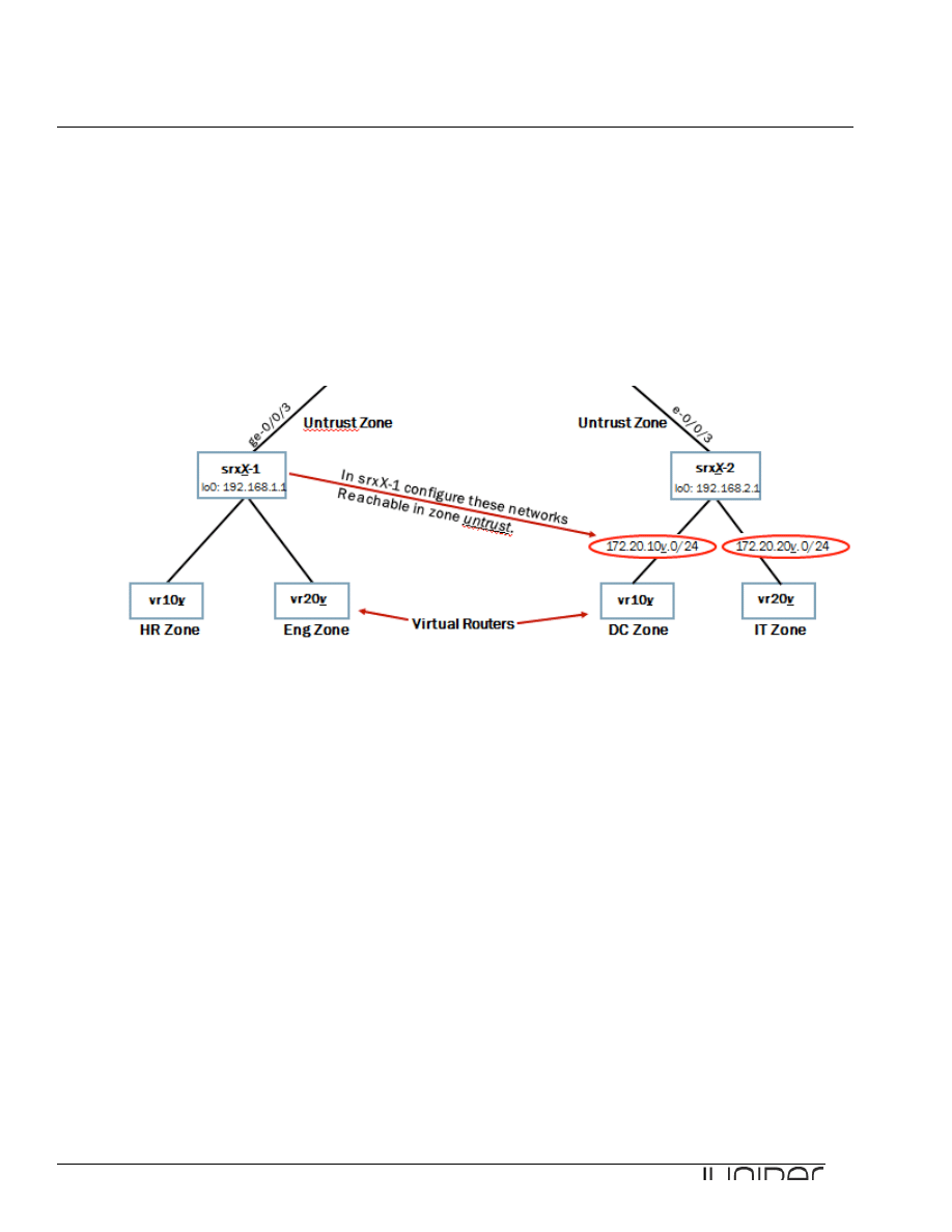
Return to the session opened with your assigned device. Referring to the lab diagram, enter configuration
mode and configure the networks associated with your POD’s other device’s virtual routers under the
untrust zone as address book addresses(Configure in srxX-1 device vr-device networks connecting to
srxX-2 device). Ensure you include the entire /24 network associated with each remote virtual router and
name the address book entries after their associated virtual router names.
[edit]
lab@host1-d# edit security zones security-zone untrust
[edit security zones security-zone untrust]
lab@host1-d# set address-book address vr108 172.20.108.0/24
[edit security zones security-zone untrust]
lab@host1-d# set address-book address vr208 172.20.208.0/24
[edit security zones security-zone untrust]
lab@host1-d# show
address-book {
address vr108 172.20.108.0/24;
address vr208 172.20.208.0/24;
}
interfaces {
ge-0/0/3.0;
}
Step 7.2
Add the remote /30 network between the Internet and the
remote student device in your pod to the untrust
zone address book. Configure this address entry to use the same name as the remote student device in
your pod.

Junos for Security Platforms
23
[edit security zones security-zone untrust]
lab@host1-d# set address-book address host2-d 172.18.2.0/30
Step 7.3
Add the Internet host’s address as an address book entry in the untrust zone. Name this entry internet-
host.
[edit security zones security-zone untrust]
lab@host1-d# set address-book address internet-host 172.31.15.1/32
Step 7.4
For the virtual routers attached to your assigned device, configure the /24 network addresses as address
book entries within their respective zones. Name these address book entries with the same name as their
associated virtual routers.
[edit security zones security-zone untrust]
lab@host1-d# up
[edit security zones]
lab@host1-d# set security-zone ?
Possible completions:
<name> Name of the zone
eng Name of the zone
hr Name of the zone
untrust Name of the zone
[edit security zones]
lab@host1-d# set security-zone hr address-book address vr107 172.20.107.0/24
[edit security zones]
lab@host1-d# set security-zone eng address-book address vr207 172.20.207.0/24
Step 7.5
Repeat the steps 7.1 – 7.4 with the other device in your POD.

Junos for Security Platforms
24
Part 8: Configuring Security Policies
In this lab part, you will establish and configure security policies that enable the necessary traffic flow
between the security zones.
Step 8.1
Create security policies named intrazone-zone-name that allow all intra-zone traffic associated with
your attached virtual routers to pass through your assigned device, where zone-name represents the
source or destination zone. (Hint: Use the any keyword to save keystrokes.)
[edit security]
lab@host1-d# edit policies from-zone hr to-zone hr policy intrazone-hr
[edit security policies from-zone hr to-zone hr policy intrazone-hr]
lab@host1-d# set match source-address any
[edit security policies from-zone hr to-zone hr policy intrazone-hr]
lab@host1-d# set match destination-address any
[edit security policies from-zone hr to-zone hr policy intrazone-hr]
lab@host1-d# set match application any
[edit security policies from-zone hr to-zone hr policy intrazone-hr]
lab@host1-d# set then permit
[edit security policies from-zone hr to-zone hr policy intrazone-hr]
lab@host1-d# up 2
[edit security policies]
lab@host1-d# edit from-zone eng to-zone eng policy intrazone-eng
[edit security policies from-zone eng to-zone eng policy intrazone-eng]
lab@host1-d# set match source-address any
[edit security policies from-zone eng to-zone eng policy intrazone-eng]
lab@host1-d# set match destination-address any
[edit security policies from-zone eng to-zone eng policy intrazone-eng]
lab@host1-d# set match application any
[edit security policies from-zone eng to-zone eng policy intrazone-eng]
lab@host1-d# set then permit
Step 8.2
Configure security policies allowing all traffic from the virtual router zones to the untrust zone. Name these
policies internet-zone-name, where zone-name represents the source zone. For this step, match on
the appropriate source address using the associated virtual router address book entries.
[edit security policies from-zone eng to-zone eng policy intrazone-eng]

Junos for Security Platforms
25
lab@host1-d# up 2
[edit security policies]
lab@host1-d# edit from-zone hr to-zone untrust policy internet-hr
[edit security policies from-zone hr to-zone untrust policy internet-hr]
lab@host1-d# set match source-address vr107
[edit security policies from-zone hr to-zone untrust policy internet-hr]
lab@host1-d# set match destination-address any
[edit security policies from-zone hr to-zone untrust policy internet-hr]
lab@host1-d# set match application any
[edit security policies from-zone hr to-zone untrust policy internet-hr]
lab@host1-d# set then permit
[edit security policies from-zone hr to-zone untrust policy internet-hr]
lab@host1-d# up 2
[edit security policies]
lab@host1-d# edit from-zone eng to-zone untrust policy internet-eng
[edit security policies from-zone eng to-zone untrust policy internet-eng]
lab@host1-d# set match source-address vr207
[edit security policies from-zone eng to-zone untrust policy internet-eng]
lab@host1-d# set match destination-address any
[edit security policies from-zone eng to-zone untrust policy internet-eng]
lab@host1-d# set match application any
[edit security policies from-zone eng to-zone untrust policy internet-eng]
lab@host1-d# set then permit
Step 8.3
Next define a security policy the rejects FTP connections sourced from the hr (device nr.1 in your POD)
and dc(device nr.2 in your POD) zones that are destined to the untrust zone. Name this policy deny-ftp-
zone-name, where zone-name is either hr or dc depending upon your assigned device.
Do not forget to commit your changes!
[edit security policies from-zone eng to-zone untrust policy internet-eng]
lab@host1-d# up 2
[edit security policies]
lab@host1-d# edit from-zone hr to-zone untrust policy deny-ftp-hr
[edit security policies from-zone hr to-zone untrust policy deny-ftp-hr]
lab@host1-d# set match source-address any
[edit security policies from-zone hr to-zone untrust policy deny-ftp-hr]
lab@host1-d# set match destination-address any
[edit security policies from-zone hr to-zone untrust policy deny-ftp-hr]
lab@host1-d# set match application junos-ftp

Junos for Security Platforms
26
[edit security policies from-zone hr to-zone untrust policy deny-ftp-hr]
lab@host1-d# set then reject
[edit security policies from-zone hr to-zone untrust policy deny-ftp-hr]
lab@host1-d# commit
commit complete
Step 8.4
Return to the session opened to the vr-device. Ensure that you cannot open an FTP session to the remote
Internet host located at 172.31.15.1. Remember to source the FTP from the routing-instance associated
with the hr zone or the dc zone depending upon your assigned device. Use the Ctrl+C key sequence to
close the FTP connection.
d1@vr-device> ftp 172.31.15.1 routing-instance vr107
Connected to 172.31.15.1.
220 vr-device FTP server (Version 6.00LS) ready.
Name (172.31.15.1:d1): ^C
Question: Were you able to initiate an FTP session to the Internet host? Why or why not?
Answer: As demonstrated in the output, the FTP session should succeed. Although you
configured a security policy explicitly rejecting this connection, policy ordering has effectively
caused the device to ignore this policy.
Step 8.5
Return to the session opened to your assigned device. Reorder the policies so that the deny-ftp-zone-
name policy appears in the list before the internet-zone-name policy, where zone-name is either
the hr or dc zone depending on your assigned device. Commit your configuration.
[edit security policies from-zone hr to-zone untrust policy deny-ftp-hr]
lab@host1-d# up
[edit security policies from-zone hr to-zone untrust]
lab@host1-d# show
policy internet-hr {
match {
source-address vr107;
destination-address any;
application any;
}
then {
permit;
}
}
policy deny-ftp-hr {

Junos for Security Platforms
27
match {
source-address any;
destination-address any;
application junos-ftp;
}
then {
reject;
}
}
[edit security policies from-zone hr to-zone untrust]
lab@host1-d# insert policy deny-ftp-hr before policy internet-hr
[edit security policies from-zone hr to-zone untrust]
lab@host1-d# show
policy deny-ftp-hr {
match {
source-address any;
destination-address any;
application junos-ftp;
}
then {
reject;
}
}
policy internet-hr {
match {
source-address vr107;
destination-address any;
application any;
}
then {
permit;
}
}
Step 8.5
Return to the session opened to the vr-device and try the FTP connection again. (Note: Exit the FTP
application by issuing the bye command.)
d1@vr-device> ftp 172.31.15.1 routing-instance vr107
ftp: connect: Connection refused
ftp> bye
Question: Were you able to initiate an FTP session to the Internet host this time?
Answer: As demonstrated in the output, the FTP session does not succeed. The reordering of
policies produces the expected behavior.

Junos for Security Platforms
28
Question: Are you able to ping the Internet host?
Answer: As demonstrated in the following output, a ping to the Internet host should succeed. If
the ping test fails, re-check your configuration.
d1@vr-device> ping 172.31.15.1 routing-instance vr107 rapid count 5
PING 172.31.15.1 (172.31.15.1): 56 data bytes
!!!!!
--- 172.31.15.1 ping statistics ---
5 packets transmitted, 5 packets received, 0% packet loss
round-trip min/avg/max/stddev = 3.831/4.789/5.588/0.716 ms
Step 8.6
Return to the session opened to your assigned device. Create a custom application named hr-gizmo
that uses UDP, a source port of 50000 and a destination port of 50001.
edit security policies from-zone hr to-zone untrust]
lab@host1-d# top
[edit]
lab@host1-d# edit applications application hr-gizmo
[edit applications application hr-gizmo]
lab@host1-d# set source-port 50000
[edit applications application hr-gizmo]
lab@host1-d# set destination-port 50001
[edit applications application hr-gizmo]
lab@host1-d# set protocol udp
[edit applications application hr-gizmo]
lab@host1-d# show
protocol udp;
source-port 50000;
destination-port 50001;
Step 8.7
Create an application set named internal-apps that includes the hr-gizmo, junos-telnet, and
junos-ping applications.
[edit applications application hr-gizmo]
lab@host1-d# up
[edit applications]
lab@host1-d# edit application-set internal-apps
[edit applications application-set internal-apps]

Junos for Security Platforms
29
lab@host1-d# set application hr-gizmo
[edit applications application-set internal-apps]
lab@host1-d# set application junos-telnet
[edit applications application-set internal-apps]
lab@host1-d# set application junos-ping
Step 8.8
Configure security policies that permit the internal-apps applications between the hr and dc security
zones. Because the hr and dc zones are separated by the Internet, you must reference the untrust
zone when configuring the security policies. Name the policy source-zone-to-destination-zone,
where source-zone matches the zone from which traffic is sourced and destination-zone matches
the zone to which the traffic is sent. Do
not use the any option in the configuration of this policy.
[edit applications application-set internal-apps]
lab@host1-d# top
[edit]
lab@host1-d# edit security policies from-zone untrust to-zone hr
[edit security policies from-zone untrust to-zone hr]
lab@host1-d# set policy dc-to-hr match source-address vr108
[edit security policies from-zone untrust to-zone hr]
lab@host1-d# set policy dc-to-hr match destination-address vr107
[edit security policies from-zone untrust to-zone hr]
lab@host1-d# set policy dc-to-hr match application internal-apps
[edit security policies from-zone untrust to-zone hr]
lab@host1-d# set policy dc-to-hr then permit
Question: How many new policies must you define to allow internal-apps traffic bi-
directionally?
Answer: Both devices within your assigned pod already have policies defined allowing all
internal traffic destined to the untrust zone (with the exception of FTP traffic). For each device
you must configure one policy allowing the internal-apps to the appropriate zone from the
untrust zone.
Step 8.9
Repeat configuration steps 8.6 - 8.8 in your POD’s other device to ensure that internal-apps traffic can be
generated from both hr and dc zones.

Junos for Security Platforms
30
Part 9: Monitoring Security Policies
In this lab part, you will monitor the results of your configuration with command outputs and logging.
Step 9.1
View the security policies in effect on your assigned device by issuing the show security policies
command and answer the following questions.
[edit security policies from-zone untrust to-zone hr]
lab@host1-d# top
[edit]
lab@host1-d# exit
Exiting configuration mode
lab@host1-d> show security policies
Default policy: deny-all
From zone: hr, To zone: hr
Policy: intrazone-hr, State: enabled, Index: 4, Sequence number: 1
Source addresses: any
Destination addresses: any
Applications: any
Action: permit
From zone: hr, To zone: untrust
Policy: deny-ftp-hr, State: enabled, Index: 7, Sequence number: 1
Source addresses: any
Destination addresses: any
Applications: junos-ftp
Action: reject
Policy: internet-hr, State: enabled, Index: 6, Sequence number: 2
Source addresses: vr107
Destination addresses: any
Applications: any
Action: permit
From zone: eng, To zone: eng
Policy: intrazone-eng, State: enabled, Index: 5, Sequence number: 1
Source addresses: any
Destination addresses: any
Applications: any
Action: permit
From zone: eng, To zone: untrust
Policy: internet-eng, State: enabled, Index: 8, Sequence number: 1
Source addresses: vr207
Destination addresses: any
Applications: any
Action: permit
From zone: untrust, To zone: hr
Policy: dc-to-hr, State: enabled, Index: 9, Sequence number: 1
Source addresses: vr108
Destination addresses: vr107
Applications: internal-apps
Action: permit

Junos for Security Platforms
31
Question: What is the total number of active security policies on your assigned device?
Answer: You should see a total of six enabled security policies. If you do not see six enabled
security policies, review your configuration steps.
Question: What command can you use to view more detailed information about security policies
such as the address book prefixes and application port information?
Answer: Use the same command with the detail option to view a more verbose output:
lab@host1-d> show security policies detail
Default policy: deny-all
Policy: intrazone-hr, action-type: permit, State: enabled, Index: 4
Policy Type: Configured
Sequence number: 1
From zone: hr, To zone: hr
Source addresses:
any: 0.0.0.0/0
Destination addresses:
any: 0.0.0.0/0
Application: any
IP protocol: 0, ALG: 0, Inactivity timeout: 0
Source port range: [0-0]
Destination port range: [0-0]
Policy: deny-ftp-hr, action-type: reject, State: enabled, Index: 7
Policy Type: Configured
Sequence number: 1
From zone: hr, To zone: untrust
Source addresses:
any: 0.0.0.0/0
Destination addresses:
any: 0.0.0.0/0
Application: junos-ftp
IP protocol: tcp, ALG: ftp, Inactivity timeout: 1800
Source port range: [0-0]
Destination port range: [21-21]
Policy: internet-hr, action-type: permit, State: enabled, Index: 6
Policy Type: Configured
Sequence number: 2
From zone: hr, To zone: untrust
Source addresses:
vr107: 172.20.107.0/24
Destination addresses:
any: 0.0.0.0/0
Application: any
IP protocol: 0, ALG: 0, Inactivity timeout: 0

Junos for Security Platforms
32
Source port range: [0-0]
Destination port range: [0-0]
Policy: intrazone-eng, action-type: permit, State: enabled, Index: 5
Policy Type: Configured
Sequence number: 1
From zone: eng, To zone: eng
Source addresses:
any: 0.0.0.0/0
Destination addresses:
any: 0.0.0.0/0
Application: any
IP protocol: 0, ALG: 0, Inactivity timeout: 0
Source port range: [0-0]
Destination port range: [0-0]
Policy: internet-eng, action-type: permit, State: enabled, Index: 8
Policy Type: Configured
Sequence number: 1
From zone: eng, To zone: untrust
Source addresses:
vr207: 172.20.207.0/24
Destination addresses:
any: 0.0.0.0/0
Application: any
IP protocol: 0, ALG: 0, Inactivity timeout: 0
Source port range: [0-0]
Destination port range: [0-0]
Policy: dc-to-hr, action-type: permit, State: enabled, Index: 9
Policy Type: Configured
Sequence number: 1
From zone: untrust, To zone: hr
Source addresses:
vr108: 172.20.108.0/24
Destination addresses:
vr107: 172.20.107.0/24
Application: internal-apps
IP protocol: udp, ALG: 0, Inactivity timeout: 60
Source port range: [50000-50000]
Destination port range: [50001-50001]
IP protocol: tcp, ALG: 0, Inactivity timeout: 1800
Source port range: [0-0]
Destination port range: [23-23]
IP protocol: 1, ALG: 0, Inactivity timeout: 60
ICMP Information: type=255, code=0
Step 9.2
Return to the session opened on the vr-device and open a Telnet session between the virtual router
associated with the hr zone and the virtual router associated with the dc zone. Be sure to source the
Telnet session from the appropriate routing-instance. Log in with the same username and password
as your current session.
d1@vr-device> telnet 172.20.108.10 routing-instance vr107
Trying 172.20.108.10...
Connected to 172.20.108.10.
Escape character is '^]'.

Junos for Security Platforms
33
vr-device (ttyp2)
login: d1
Password:
--- JUNOS 9.2R1.10 built 2008-08-07 06:45:07 UTC
NOTE: This router is divided into many virtual routers used by different teams.
Please only configure your own virtual router.
You must use 'configure private' to configure this router.
d1@vr-device>
Step 9.3
Return to the session opened on your assigned device and issue the show security flow session
command.
lab@host1-d> show security flow session
Session ID: 60852, Policy name: self-traffic-policy/1, Timeout: 1800
In: 10.210.14.130/33625 --> 10.210.14.137/23;tcp, If: ge-0/0/0.0
Out: 10.210.14.137/23 --> 10.210.14.130/33625;tcp, If: .local..0
Session ID: 63045, Policy name: internet-hr/6, Timeout: 1710
In: 172.20.107.10/55798 --> 172.20.108.10/23;tcp, If: ge-0/0/4.107
Out: 172.20.108.10/23 --> 172.20.107.10/55798;tcp, If: ge-0/0/3.0
2 sessions displayed
Question: What is the session ID for the Telnet session you opened?
Answer: The answer varies, but in the output from srxB-1, the session ID is 60852.
Step 9.3
Using the session ID, view a more detailed output of the open Telnet session and answer the following
question.
lab@host1-d> show security flow session session-identifier 60852
Session ID: 60852, Status: Normal
Flag: 0x40
Policy name: self-traffic-policy/1
Source NAT pool: Null, Application: junos-telnet/10
Maximum timeout: 1800, Current timeout: 1800
Start time: 6221927, Duration: 9369
In: 10.210.14.130/33625 --> 10.210.14.137/23;tcp,

Junos for Security Platforms
34
Interface: ge-0/0/0.0,
Session token: 0xc0, Flag: 0x4129
Route: 0x20010, Gateway: 10.210.14.130, Tunnel: 0
Port sequence: 0, FIN sequence: 0,
FIN state: 0,
Out: 10.210.14.137/23 --> 10.210.14.130/33625;tcp,
Interface: .local..0,
Session token: 0x80, Flag: 0x4144
Route: 0xfffb0006, Gateway: 10.210.14.137, Tunnel: 0
Port sequence: 0, FIN sequence: 0,
FIN state: 0,
1 sessions displayed
Question: How many seconds remain before the Telnet session times out (without further
activity)?
Answer: The answer varies, but in the output from srxB-1, 1632 seconds remain. If there is no
further activity during this period, the session closes.
Step 9.4
To view flow based statistics per interface through which traffic is either permitted or denied use show
interfaces extensive command. Filter the output by using pipe and
find "Flow Statistics".
Use this command and generate various types of traffic between the outputs to see the changes in the
counter values of the output of each command.
lab@host1-d> show interfaces extensive ge-0/0/3 | find "Flow Statistics"
Flow Statistics :
Flow Input statistics :
Self packets : 640
ICMP packets : 5
VPN packets : 0
Multicast packets : 0
Bytes permitted by policy : 44058
Connections established : 640
Flow Output statistics:
Multicast packets : 0
Bytes permitted by policy : 28509
Flow error statistics (Packets dropped due to):
Address spoofing: 0
Authentication failed: 0
Incoming NAT errors: 0
Invalid zone received packet: 0
Multiple user authentications: 0
Multiple incoming NAT: 0
No parent for a gate: 0
No one interested in self packets: 0
No minor session: 0

Junos for Security Platforms
35
No more sessions: 0
No NAT gate: 0
No route present: 0
No SA for incoming SPI: 0
No tunnel found: 0
No session for a gate: 0
No zone or NULL zone binding 0
Policy denied: 0
Security association not active: 0
TCP sequence number out of window: 0
Syn-attack protection: 0
User authentication errors: 0
Protocol inet, MTU: 1500, Generation: 198, Route table: 0
Flags: None
Addresses, Flags: Is-Preferred Is-Primary
Destination: 172.18.1.0/30, Local: 172.18.1.2, Broadcast: 172.18.1.3,
Generation: 238
You have completed Lab 1 !
Wyszukiwarka
Podobne podstrony:
Lab1 JSEC Zones and Policies
Flavon Policies and Procedures 20120611
Great?pression Roosevelt and Hoover's Policies in Handli
HIPAA and Information Security Policies
USE OF ENGLISH Anne Wil Harzing Language competencies, policies and practices in multinational corp
83 Group tactics using sweeper and screen players in zones
Dead zones of the imagination On violence, bureaucracy, and interpretive labor David GRAEBER
82 Group tactics using sweeper and using screens zones
COMPENDIUM CULTURAL POLICIES AND TREDNDS IN EUROPE
Kwiek, Marek Globalisation Re Reading Its Impact on the Nation State, the University, and Education
Flora Synanthropization and Anthropopressure Zones in a Large Urban Agglomeration (Exemplified by Wa
Postmodernity and Postmodernism ppt May 2014(3)
Scoliosis and Kyphosis
L 3 Complex functions and Polynomials
4 Plant Structure, Growth and Development, before ppt
Osteoporosis ľ diagnosis and treatment
05 DFC 4 1 Sequence and Interation of Key QMS Processes Rev 3 1 03
więcej podobnych podstron