
TECHNICAL REPORT
RAPPORT TECHNIQUE
TECHNISCHER BERICHT
CEN/TR 15281
May 2006
ICS 13.230
English Version
Guidance on Inerting for the Prevention of Explosions
Atmosphères explosibles - Guide de l'inertage pour la
prévention des explosions
This Technical Report was approved by CEN on 8 November 2005. It has been drawn up by the Technical Committee CEN/TC 305.
CEN members are the national standards bodies of Austria, Belgium, Cyprus, Czech Republic, Denmark, Estonia, Finland, France,
Germany, Greece, Hungary, Iceland, Ireland, Italy, Latvia, Lithuania, Luxembourg, Malta, Netherlands, Norway, Poland, Portugal, Romania,
Slovakia, Slovenia, Spain, Sweden, Switzerland and United Kingdom.
EUROPEAN COMMITTEE FOR STANDARDIZATION
C O M I T É E U R O P É E N D E N O R M A L I S A T I O N
E U R O P Ä I S C H E S K O M I T E E F Ü R N O R M U N G
Management Centre: rue de Stassart, 36 B-1050 Brussels
© 2006 CEN
All rights of exploitation in any form and by any means reserved
worldwide for CEN national Members.
Ref. No. CEN/TR 15281:2006: E

2
Contents
Page
Foreword..............................................................................................................................................................4
1
Scope ......................................................................................................................................................5
2
Normative references ............................................................................................................................5
3
Terminology and abbreviations ...........................................................................................................6
3.1
Terminology ...........................................................................................................................................6
3.2
Abbreviations .........................................................................................................................................7
4
Inert gases ..............................................................................................................................................8
5
Influence of the oxygen concentration on explosive atmospheres .................................................9
5.1
General....................................................................................................................................................9
5.2
Gas and vapour explosions............................................................................................................... 10
5.3
Dust explosions .................................................................................................................................. 13
5.4
Hybrid mixtures................................................................................................................................... 15
5.5
Mists..................................................................................................................................................... 15
5.6
Influence of process parameters ...................................................................................................... 15
6
Methods of Inerting............................................................................................................................. 18
6.1
General................................................................................................................................................. 18
6.2
Pressure swing inerting ..................................................................................................................... 19
6.3
Vacuum-swing inerting ...................................................................................................................... 19
6.4
Flow-through inerting......................................................................................................................... 20
6.5
Displacement inerting ........................................................................................................................ 21
6.6
Maintaining inert conditions.............................................................................................................. 21
7
Inerting systems ................................................................................................................................. 23
7.1
General introduction .......................................................................................................................... 23
7.2
Inert gas supply .................................................................................................................................. 23
7.3
Monitoring and control system ......................................................................................................... 24
7.4
Methods ............................................................................................................................................... 25
8
Reliability ............................................................................................................................................. 27
8.1
Demands for safety critical equipment ............................................................................................ 27
8.2
Inerting systems ................................................................................................................................. 28
9
Personnel and environmental protection......................................................................................... 28
10
Information for use ............................................................................................................................. 29
Annex A (informative) Oxygen monitoring technology .............................................................................. 30
Annex B (informative) Equations for pressure-swing inerting .................................................................. 33
Annex C (informative) Calculations for flow-through inerting................................................................... 36
Annex D (informative) Addition of solids to an inerted vessel using a double valve arrangement ...... 38
Annex E (informative) Addition of solids down a charge-chute to an open vessel ................................ 41
Annex F (informative) Examples on inerting specific items of process equipment................................ 45
Annex G (informative) Prevention of diffusion of air down vent pipes..................................................... 50
Bibliography ..................................................................................................................................................... 52
CEN/TR 15281:2006

3
Figures
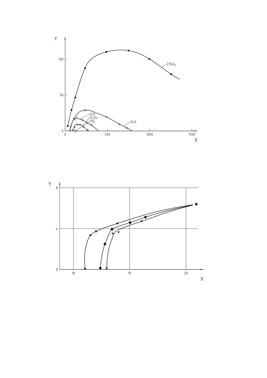
Figure 1 — Influence of inert gas on explosion limits of methane (according to [32], Figure 28)...........10
Figure 2 — Flammability diagram for air-propane-nitrogen (according to [8])..........................................11
Figure 3 — Triangular flammability diagram for fuel-oxygen-nitrogen ......................................................12
Figure 4 — Influence of oxygen concentration on the explosion pressure of brown coal (according to
[7])...............................................................................................................................................................13
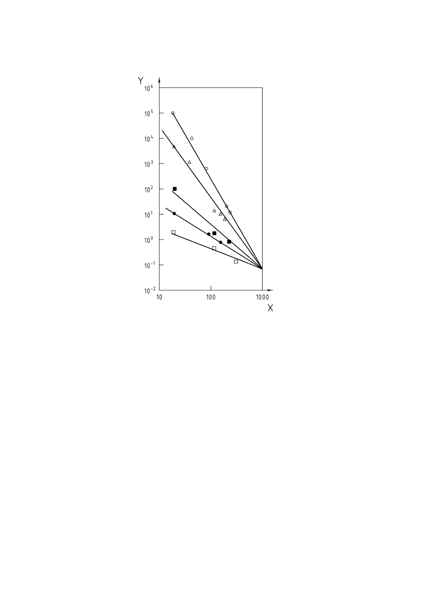
Figure 5 — Influence of oxygen concentration on the rate of explosion pressure rise of brown coal
(according to [7]) .......................................................................................................................................14
Figure 6 — Influence of oxygen concentration on maximum explosion pressure for brown coal
(according to [29]).....................................................................................................................................14
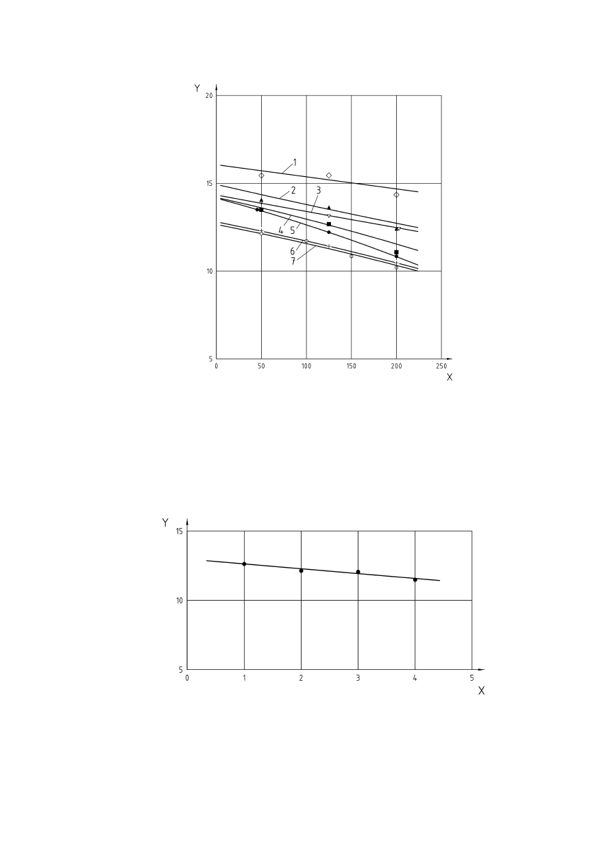
Figure 7 — Effect of temperature on ignition sensitivity of dusts (according to [7])................................16
Figure 8 — Temperature influence on limiting oxygen concentration (according to [29]).......................17
Figure 9 — Influence of pressure on inerting brown coal (according to [29]) ...........................................17
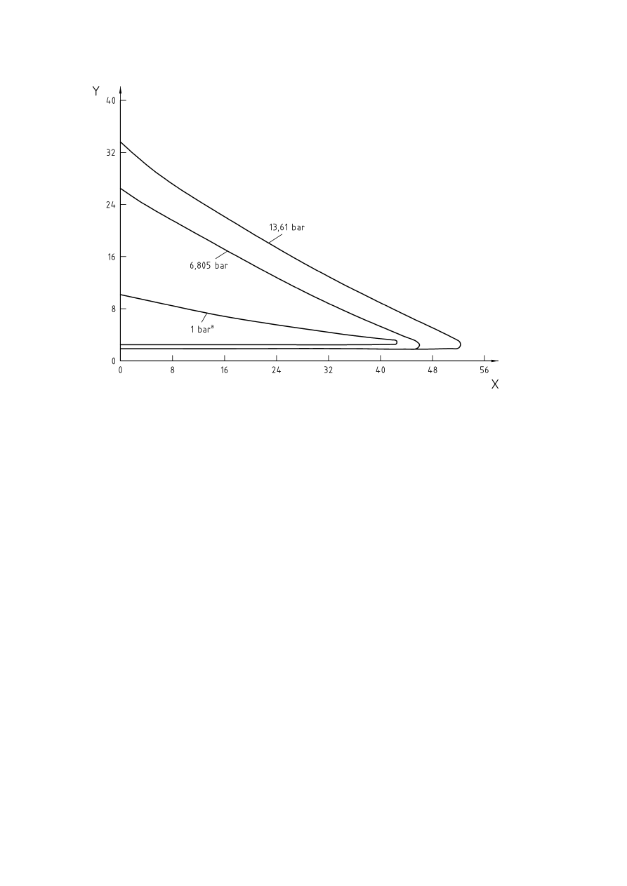
Figure 10 — Pressure influence on amount of inert gas required for inerting propane (according to [32],
Figure 40) ...................................................................................................................................................18
Figure 11 — Specification of safe limits for control
.....................................................................................25
Figure D.1 — Example of addition of solids for an inerted vessel using a double value arrangement ..38
Figure F.1 — Agitated pressure filter/dryer ...................................................................................................45
Figure F.2 — Top discharge centrifuge..........................................................................................................46
Figure F.3 — Inverting filter horizontal basket centrifuge ...........................................................................47
Figure F.4 — Pinned disc grinding mill..........................................................................................................48
Figure F.5 — Horizontal paddle dryer ............................................................................................................49
Figure G.1 — Value of exponent N in equation [18] for various pipe diameters .......................................51
Tables
Table B.1 — Typical rates of pressure rise for vacuum systems................................................................35
Table B.2 — Selected values of k = C
p
/C
v
for various inert gases...............................................................35
CEN/TR 15281:2006

4
Foreword
This Technical Report (CEN/TR 15281:2006) has been prepared by Technical Committee CEN/TC 305
“Potentially explosive atmospheres – Explosion prevention and protection”, the secretariat of which is held by
DIN.
CEN/TR 15281:2006

5
1 Scope
Inerting is a measure to prevent explosions. By feeding inert gas into a system which is to be protected
against an explosion, the oxygen content is reduced below a certain concentration until no explosion can
occur. The addition of sufficient inert gas to make any mixture non-flammable when mixed with air (absolute
inerting) is only required in rare occasions. The requirements for absolute inerting will be discussed. Inerting
may also be used to influence the ignition and explosion characteristics of an explosive atmosphere.
The guidance given on inerting is also applicable to prevent an explosion in case of a fire.
The following cases are not covered by the guideline:
admixture of an inert dust to a combustible dust;
inerting of flammable atmospheres by wire mesh flame traps in open spaces of vessels and tanks;
fire fighting;
avoiding an explosive atmosphere by exceeding the upper explosion limit of a flammable substance.
Inerting which is sufficient to prevent an explosion is not a protective measure to prevent fires, self-ignition,
exothermic reactions or a deflagration of dust layers and deposits.
2 Normative
references
The following referenced documents are indispensable for the application of this document. For dated
references, only the edition cited applies. For undated references, the latest edition of the referenced
document (including any amendments) applies.
EN 1127-1:1997, Explosive atmospheres – Explosion prevention and protection – Part 1: Basic concepts and
methodology.
EN 14034-4, Determination of explosion characteristics of dust clouds – Part 4: Determination of the limiting
oxygen concentration LOC of dust clouds.
prEN 14756, Determination of the limiting oxygen concentration (LOC) for gases and vapours.
EN 50104, Electrical apparatus for the detection and measurement of oxygen – Performance requirements
and test methods.
IEC 61508-1, Functional safety of electrical/electronic/programmable electronic safety-related systems –
Part 1: General requirements (IEC 61508-1:1998 + Corrigendum 1999)
IEC 61508-2, Functional safety of electrical/electronic/programmable electronic safety-related systems –
Part 2: Requirements for electrical/electronic/programmable electronic safety- related systems (IEC 61508-
2:2000).
IEC 61508-3, Functional safety of electrical/electronic/programmable electronic safety-related systems –
Part 3: Software requirements (IEC 61508-3:1998 + Corrigendum 1999).
IEC 61511-1, Functional safety – Safety instrumented systems for the process industry sector – Part 1:
Framework, definitions, system, hardware and software requirements (IEC 61511-1:2003 + corrigendum
2004).
IEC 61511-2, Functional safety – Safety instrumented systems for the process industry sector – Part 2:
Guidelines for the application of IEC 61511-1 (IEC 61511-2:2003).
IEC 61511-3, Functional safety – Safety instrumented systems for the process industry sector – Part 3:
Guidance for the determination of the required safety integrity levels (IEC 61511-3:2003 + corrigendum 2004).
CEN/TR 15281:2006

6
3 Terminology and abbreviations
For the purposes of this Technical Report, the terms and definitions given in EN 1127-1:1997 and the
following apply.
3.1 Terminology
3.1.1
inerting
replacement of atmospheric oxygen in a system by a non-reactive, non-flammable gas, to make the
atmosphere within the system unable to propagate flame
3.1.2
absolute inerting
absolutely inerted mixture is one which does not form a flammable atmosphere when mixed with air in any
proportion because the ratio of inert to fuel is sufficiently high
3.1.3
Limiting Oxygen Concentration (LOC)
experimentally determined oxygen concentration which will not allow an explosion in a fuel/air/inert gas
mixture
NOTE
It is a characteristic which is specific for a given fuel/inert gas combination. The determination should be in
accordance with pr EN 14756 for gases and vapours and EN 14034-4 for dusts respectively.
3.1.4
Maximum Allowable Oxygen Concentration (MAOC)
concentration which should not be exceeded in the system which has to be protected, even with anticipated
upsets or operating errors
NOTE
It is set using a margin below the limiting oxygen concentration. This margin should consider variations in
process conditions which might deviate from the experimental conditions.
3.1.5
explosion
abrupt oxidation or decomposition reaction producing an increase in temperature, pressure, or in both
simultaneously
[EN 1127-1:1997, 3.6]
3.1.6
Lower Explosion Limit (LEL)
lower limit of the explosion range
3.1.7
Upper Explosion Limit (UEL)
upper limit of the explosion range
3.1.8
explosion range
range of concentration of a flammable substance in air within which an explosion can occur
3.1.9
Trip Point (TP)
oxygen concentration at which the oxygen monitoring instrumentation initiates a shut down procedure to make
the equipment safe and prevent the atmosphere inside from becoming flammable
CEN/TR 15281:2006

7
3.1.10
Set Point (SP)
oxygen concentration at which the oxygen monitoring instrumentation controls the flow, pressure or quantity of
inert gas
NOTE
A suitable allowance for variation of flows, temperatures and pressure fluctuations should be made to ensure
that when the oxygen level reaches the set point, the control system can prevent the oxygen level from rising to the trip
point under normal operation and foreseeable disturbances.
3.1.11
safety margin
difference between the trip point and the maximum allowable oxygen concentration
3.1.12
inert gas
gas that neither reacts with oxygen nor with the gas, vapour or dust
3.1.13
pressure-swing inerting
reduction of oxidant concentration in a closed system by pressurising with inert gas and venting back to
atmospheric pressure
3.1.14
vacuum-swing inerting
reduction of oxidant concentration by the evacuation of a closed system, and the restoration to atmospheric
pressure by the admission of inert gas
3.1.15
flow-through inerting
replacement of an oxidant by a continuous flow of inert gas into a system which is vented to atmosphere
3.1.16
displacement inerting
displacement of an oxidant by an inert gas of a significantly different density, where significant mixing does not
take place
3.2 Abbreviations
B
bulk density of powder
C
0
initial oxygen concentration (fractional)
C
b
oxygen concentration in air in powder (usually 0,21) (fractional)
C
f
oxygen concentration after flow purging (fractional)
C
i
concentration of oxygen in inert gas
C
m
maximum allowable oxygen concentration
C
n
oxygen concentration after n purges
C
p
specific heat of inert gas at constant pressure
C
st
stoichometric composition of the fuel in air
C
r
required maximum fractional oxygen concentration in vessel
C
v
specific heat of inert gas at constant volume
D vent diameter, inches
F safety factor for flow purging
f void fraction
h distance from end of vent, ft
J rate of pressure rise in a vacuum system, mbar min
-1
CEN/TR 15281:2006

8
K
weight of 1 bag of powder
k ratio of specific heats of gases, C
p
/C
v
LOC
limiting oxygen concentration
M mean partical size, µm
MAOC maximum allowable concentration
MOC
C
minimum oxygen for combustion with carbon dioxide as diluent
MOC
N
minimum oxygen for combustion with nitrogen as diluent
m
molecular weight of purge gas
N
exponent in Husa’s 1964 equation dependent on vent diameter
n
number of cycles or additions
P
1
lower purge pressure (absolute)
P
2
upper purge pressure (absolute)
Q purge gas flow-rate
R
upper/lower purge pressure ratio (absolute), i.e. P
2
/P
1
S
void fraction of bulk powder
SP
set
point
TP
trip point
t
time
t*
time interval between start of charging of successive bags
U
vessel ullage volume
V system
volume
V
0
volume of oxygen in vessel at start
V*
volume of oxygen in each bag
V
n
volume of oxygen in vessel after n
th
bag charged
V
s
bulk volume of solids being charged
V
v
volume of double valve arrangement
v
purge gas superficial velocity, ft/sec
v/v
volume/volume
x
required oxygen content % v/v
NOTE
Where units have specific units, then these should be used. Where no units are shown, the variables are
either dimensionless or any consistent set of units may be applied to the equation.
4 Inert
gases
Inerting may be achieved by using a non-flammable gas which will neither react with a given fuel nor with
oxygen. This has to be considered carefully. Some material may react with steam, carbon dioxide or even
nitrogen under some conditions. For example, molten lithium metal reacts with nitrogen.
The most commonly used inert gases are:
a) Nitrogen
Nitrogen may either be received from a commercial supplier with an appropriate purity or may be
generated from ambient air at technical quality by on-site facilities.
b) Carbon
dioxide
Carbon dioxide may be received from a commercial supplier at an appropriate purity.
CEN/TR 15281:2006

9
c) Steam
Steam with pressures over 3 bar might be used as an inert gas, as its oxygen content is usually negligible.
Condensation has to be taken into account and might lead to a pressure drop which supports air ingress
into the plant or create a vacuum. When using steam for fire fighting in dust plants the condensation can
be an advantage as the dust becomes wet, preventing a dust dispersion and extinguishing smoulders.
However, there can be a risk of increased mass, chemical reaction due to the water, or microbial activity.
d) Flue
gases
Flue gases from combustion can be used if the oxygen concentration can be controlled sufficiently.
Fluctuations in oxygen concentration have to be taken into account, and appropriate measures to
minimise fluctuations have to be taken (e.g. gas buffer storage). Flue gases shall be assumed to be
similar to nitrogen when defining the limiting oxygen concentration.
e) Noble
gases
Argon or other noble gas may be received from a commercial supplier at an appropriate purity. Their use
will be limited due to economic reasons to applications where no other inert gas can be identified. Helium
may be advantageous as an inerting medium where hydrogen is used, as the molecular size of helium
approaches that of the hydrogen, so leaks may be more readily detected.
5 Influence of the oxygen concentration on explosive atmospheres
5.1 General
Limiting oxygen concentrations are measured in air for a given fuel by reducing the oxygen concentration and
varying the fuel concentration until an explosion is no longer observed. The limiting oxygen concentration
depends on the type of inert gas used, the temperature, and the pressure of the system. The effect of various
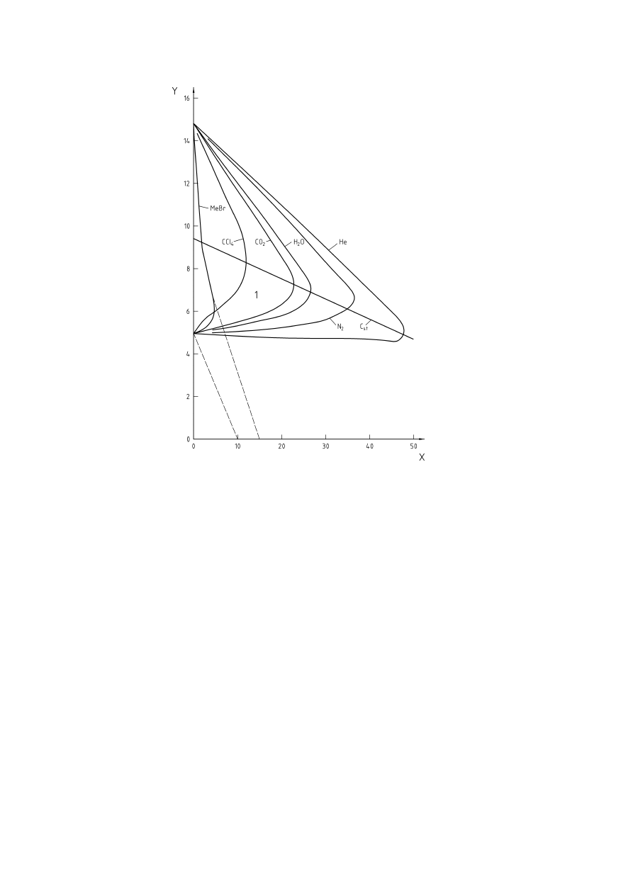
inert gases is shown in Figure 1.
The higher the concentration of inert gas required for inerting, the lower is the limiting oxygen concentration.
Limiting Oxygen Concentrations for several gases and vapours are given in [9] and [24], and have been
determined using the method outlined in prEN 14756. Other available values generally quoted in the open
literature may have been obtained using a different method, and due care should be exercised when using
such values unless the method used is known to give comparable results to the method of prEN 14756.
CEN/TR 15281:2006
10
Key
% air
=
100 % - % methane - % inert
X
=
Added inert, volume-percent
Y = Methane,
volume-percent
1 = Flammable
mixtures
C
st
=
stoichometric composition of the fuel in air
Figure 1 — Influence of inert gas on explosion limits of methane (according to [32], Figure 28)
The experimentally determined limiting oxygen concentration is a fuel and inert gas specific characteristic.
Therefore both components have to be defined to give an appropriate value for the limiting oxygen
concentration (see prEN 14756 for gases and EN 14034-4 for dusts). The following information is required:
gases and vapours: composition;
dusts:
composition, particle size, moisture content;
inert gas:
composition and oxygen content.
5.2 Gas and vapour explosions
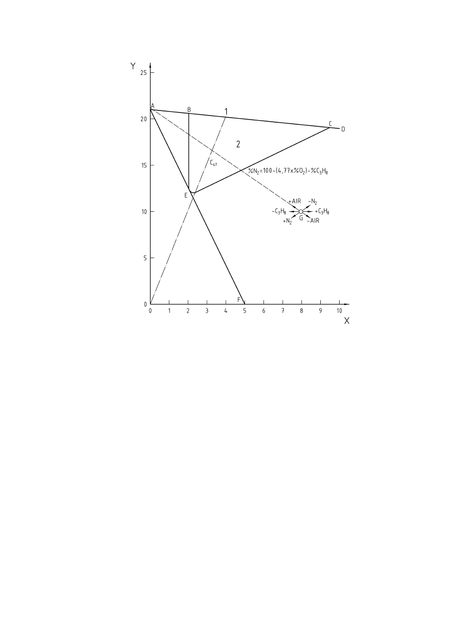
The explosible range of a flammable gas under the given process conditions can be shown in a suitable
flammability diagram. Figure 2 shows such a diagram on rectangular coordinates for a mixture of a fuel, air
and an inert gas (Note that ATEX does not cover oxygen enriched atmospheres so the diagram is limited to
21% oxygen). Values for limiting oxygen concentration for various materials and mixtures are given in [9] and
[24].
CEN/TR 15281:2006
11
Key
X = Propane
(C
3
H
8
), % v/v
Y
=
Oxygen, % v/v
1
=
Impossible mixtures above ABCD
2
=
Only BEC flammable
C
st
=
stoichometric composition of the fuel in air
Figure 2 — Flammability diagram for air-propane-nitrogen (according to [8])
Absolute inerting is established when inert gas is added to the explosible mixture to such an extent, that by
addition of any amount of air or fuel the explosible range can no longer be reached. The release of such an
inerted atmosphere to the ambient air would thus not result in the formation of an explosive atmosphere.
Absolute inerting is achieved in Figure 2 if the composition of the inerted mixture lies in the area below and to
the left of the line drawn from 21 Vol.-% oxygen apex (point A) and a tangent to the explosible range (point E),
cutting the ordinate at point F. Any mixture with less than 5 % propane will always be non-explosible when
mixed with air, and therefore is absolutely inert.
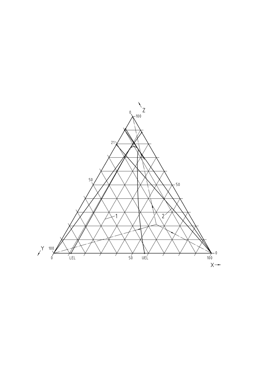
Sometimes data are only available for fuel-oxygen-inert gas mixtures, so the diagram may be constructed on
triangular coordinates with oxygen as one of the axes, and the diagram can then be used for determining the
flammable limits in air. This is shown in Figure 3. Each point within the triangular diagram corresponds to a
certain composition of the mixture. The apices of the triangle represent the pure components, and points
along the sides of the triangle give the two-component mixtures. The concentration of one component can be
determined from the distance of the mixture point to the side of the triangle opposite to its apex of the triangle.
If one of the three components is added to the mixture, the concentration changes along the straight line
CEN/TR 15281:2006
12
between the mixture point and the triangle apex of the added component. The ratio between the two other
components of the mixture does not change if the third component is fed into the system.
If nitrogen is the inert gas, the air composition can be fixed along the side for inert gas-oxygen at 21 Vol.-%
oxygen. The line connecting this point with the triangle apex of the fuel marks all compositions which can
occur for a fuel/air-mixture. This line crosses the limits of the explosible range giving the lower and upper
explosions limits of the fuel in air.
When inert gas is added the concentration changes along the straight line towards the triangle apex for inert
gas. To determine whether the explosible range can be entered again by adding oxygen or fuel, lines are
drawn from the oxygen or fuel apex respectively.
Key
X = Fuel
Y = Oxygen
Z = Nitrogen
1 = Explosible
range
2 = Fuel-air-mixtures
Figure 3 — Triangular flammability diagram for fuel-oxygen-nitrogen
Flammability data for gases, vapours or dusts should be determined using the methods specified in
prEN 14756 or EN 1839. Data using these methods can be found in the literature such as [9] for pure
substances, and in [24] for mixtures. Where values are found from the open literature then, unless it is known
that the method used gives comparable results to those determined using EN 1839 and prEN 14756, the
reliability of the data should be carefully checked.
CEN/TR 15281:2006
13
5.3 Dust
explosions
Dust concentrations cannot be controlled as gas or vapour concentrations can. Therefore only the oxygen
concentration can be varied in this case, and the variation of the limiting oxygen concentration with the dust
concentration cannot be taken into account for practical applications.
It has to be pointed out that in this case the required reliability of the inerting system depends on the likelihood
of the ignition source in the process.
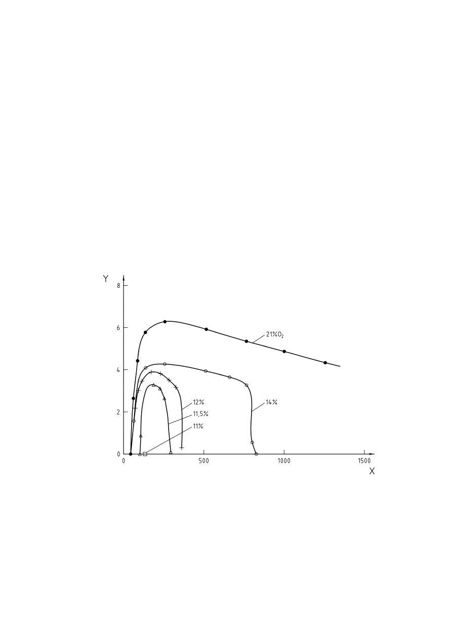
The influence of oxygen concentration on explosion pressure and rate of pressure rise for brown coal are
shown in Figures 4 and 5, and the effect of various inert gases on the maximum pressure for brown coal is
shown in Figure 6.
Note that some dusts such as metals may have limiting oxygen for combustion concentrations as low as
2 % v/v. The limiting oxygen concentration should be determined using the method described in EN 14034-4.
Although the limiting oxygen concentration for many dusts is presented in the open literature, care is required
as many literature sources do not specify the method used. Hence unless the data is known to be reliable and
determined by the method specified in EN 14034-4 or a method which gives comparable results, then the
limiting oxygen concentration should be determined experimentally using the method of EN 14034-4.
Similarly, dusts may have differences in purity, and so a literature value may not be valid for a particular dust
as the composition may be different. This is particularly valid where naturally occurring materials such as flour,
wood dust or coal are handled.
Key
X
=
Dust concentration [g/m
3
]
Y
=
Explosion pressure [bar]
Figure 4 — Influence of oxygen concentration on the explosion pressure of brown coal
(according to [7])
CEN/TR 15281:2006
14
Key
X
=
Dust concentration [g/m
3
]
Y
=
Rate of explosion pressure rise [bar/s]
Figure 5 — Influence of oxygen concentration on the rate of explosion pressure rise of brown coal
(according to [7])
Key
Initial temperature 150 °C
X
=
Oxygen concentration [Vol.-%]
Y
=
Maximum explosion gauge pressure [bar]
= Nitrogen
= Steam
= Carbon
dioxide
Figure 6 — Influence of oxygen concentration on maximum explosion pressure for brown coal
(according to [29])
CEN/TR 15281:2006

15
5.4 Hybrid
mixtures
Where dusts and vapours are present together, they will form a hybrid mixture. This may be flammable even
though the dust and vapour are each below their own lower explosion limit. Hence it is difficult to predict
whether such a hybrid mixture is flammable.
The limiting oxygen concentration of such a hybrid mixture will not be less than the lowest value of any of the
components. The lowest value should be used unless experimental work indicates that a higher concentration
is acceptable.
5.5 Mists
Mists of liquids may be flammable well below the flash point of the liquid, and hence should be considered to
be flammable at all temperatures. The limiting oxygen concentration of a mist should be considered to be the
same as the limiting oxygen concentration of its vapour.
5.6 Influence of process parameters
Where dusts are handled, the minimum ignition energy decreases markedly with an increase in temperature,
converging at about 0,1 mJ at about 1000 °C, as shown in Figure 7. Figure 8 shows the effect of temperature
on the limiting oxygen concentration for several dusts.
With increasing temperature there is a decrease in the limiting oxygen concentration. For hydrocarbons a
decrease of the limiting oxygen concentration of 1 Vol.-% per 100 °K to 2 Vol.-% per 100 °K was determined.
There are exceptions to this rule such as halogenated hydrocarbons. By raising the temperature from ambient
to 100 °C the LOC for methylene chloride decreases from 20,3 Vol.-% to 9,5 Vol.-%. Small quantities of
impurities can also have an effect on the flammability of gases and vapours. For example, methylene chloride
alone is non-flammable in air below 100 °C and at 760 mmHg, but with 0,5 % by volume of methanol vapour
added, it becomes flammable at 27 °C, according to [12].
CEN/TR 15281:2006
16
Key
X
=
Temperature T [°C]
Y
=
Lowest minimum ignition energy (LMIE) [mJ]
{
= Melamine
Ì
= Sewage
sludge
= Pea
flour
= Herbicide
= Lycopodium
Figure 7 — Effect of temperature on ignition sensitivity of dusts (according to [7])
An increase in the initial pressure may also lead to a decrease in the maximum allowed oxygen concentration.
For example a rise in pressure from 1 to 4 bar resulted in a decrease of the limiting oxygen concentration of
1 Vol.-% max. for brown coal (Figure 9). Vice versa, the amount of inert gas required for inerting rises with
increasing pressure (Figure 10).
CEN/TR 15281:2006
17
Key
X
=
Initial temperature [°C]
Y
=
Maximum allowed oxygen concentration [Vol.-%]
1
=
Skim milk powder, M = 65 µm
2
=
Bituminous coal, M = 19 µm
3
=
Long flame coal, M = 19 µm
4
=
Peat, M = 46 µm
5
=
Beech wood dust, M = 59 µm
6
=
Gelling medium, M = 43 µm
7
=
Brown coal, M = 52 µm
Figure 8 — Temperature influence on limiting oxygen concentration (according to [29])
Key
X = Initial
pressure
[bar]
Y
=
Maximum allowed oxygen concentration [Vol.-%]
Figure 9 — Influence of pressure on inerting brown coal (according to [29])
CEN/TR 15281:2006
18
Key
% Air
=
100 % - % Propane - % N
2
X
=
Added nitrogen [Vol.-%]
Y = Propane
[Vol.-%]
Figure 10 — Pressure influence on amount of inert gas required for inerting propane
(according to [32], Figure 40)
6 Methods of Inerting
6.1 General
There are four recognised methods of inerting a system, which are detailed below. These are:
a) Pressure
swing
inerting
This method pressurises the system with inert gas and vents down to atmospheric pressure. The cycle is
repeated until the required oxygen concentration is reached. It is only suitable for a system which can be
pressurised.
b) Vacuum swing inerting
This is similar to pressure swing inerting, but evacuates the system and releases the vacuum with inert
gas. This method is suitable where a system can withstand vacuum but not pressure, such as glass
vessels.
c) Flow through inerting
This method feeds inert gas at one point and simultaneously vents gas at another point remote from the
feed point. This method is suitable for a system that cannot withstand either internal or external pressure.
Also, in a long thin vessel or pipeline, pressure or vacuum swing inerting may be ineffective due to poor
mixing if the gas is fed and removed from the same end, so the flow through method would be applicable.
CEN/TR 15281:2006

19
d) Displacement
inerting
This method relies on a large density difference between the inert gas and the air being removed. It is
usually only suitable for specialised situations where there is a large density difference and mixing is likely
to be poor.
6.2 Pressure swing inerting
This is a very efficient method to adopt as it enables the gases to mix readily. The pressure system is closed
and pressurised using an inert gas. The system is then vented to atmosphere, and the process repeated until
the required reduction in the oxygen content is achieved. The theoretical oxygen content after a given number
of pressure and relieve cycles can be calculated by using partial pressures from the equation given in
Annex B.
Where the inert gas supply contains some oxygen, it is necessary to take this into account when calculating
the purging requirements. The term C
i
is used for this purpose, and where the oxygen content of the inert gas
supply is zero, C
i
becomes zero.
The basic equation in Annex B assumes that the expansion and compression is isothermal, and this will be
the case for most situations. However, where the compression or expansion involves high pressure or vacuum,
or rapid pressure changes, then the compression or expansion may be adiabatic. Under such conditions the
oxygen reduction will be less than that calculated by the basic equation, and the modified equation given in
Annex B should be used. Users should satisfy themselves that the appropriate equation has been selected.
Examples of the choice of equation are also given in Annex B. Reverse solutions to the equations are given to
simplify the application of the equation.
Where a system is large and contains branches, the gas in the closed ends of the system will be compressed
by the inert gas, but it is unlikely to mix well. Thus when the pressure is released, the gas will simply expand,
and the oxygen content in the branches will remain similar to that before it was compressed. Therefore it will
be necessary to take account of this branching when calculating the final oxygen content.
Where the system is very complex, it may be necessary to release the inert gas pressure from each branch in
turn to ensure adequate displacement of the original gas. If this requires a large number of purges, then a
vacuum purging system may be better.
Whilst the above equations may be used to infer the oxygen concentration in any system, it may not be
accurate for a complex branched system. In a system consisting of one vessel, inferring the oxygen
concentration will usually be sufficient but where the system is complex, it will be necessary to actually
measure the oxygen concentration at several points in the system.
Once oxygen measurements have been undertaken and found to be acceptable, then it is usually satisfactory
for normal operation to infer that the oxygen concentration is the same as during the test, providing exactly the
same purging conditions are used as were used in the test. For equipment with high speed or close-clearance
moving parts, such as centrifuges and wiped film evaporators, continuous oxygen monitoring should be used.
Where a system is operated under pressure, any leaks will be of inert gas into the workplace. Therefore
adequate precautions should be taken to ensure that personnel cannot be asphyxiated by any escape of inert
gas. Where systems are located in the open air, asphyxiation will only present a risk under conditions of gross
leakage. In closed workplaces, adequate ventilation should be provided. Local regulations should be
consulted for guidance on ventilation.
6.3 Vacuum-swing
inerting
This method can be used where a vessel cannot be subjected to internal pressure, but will withstand full
vacuum. Examples in this category are glass vessels. Where low pressure bursting discs are fitted to a vessel,
it is essential that they are fitted with a vacuum support, otherwise the disc will burst into the vessel.
NOTE 1
Further information on the selection and installation of bursting discs is contained within EN ISO 4126-6.
CEN/TR 15281:2006

20
The procedure is similar to that for pressure swing purging, but, since the vessel is under vacuum, it is
possible that air ingress may occur, thus rendering the inert gas less effective than calculated. Therefore, the
equations in Annex B for pressure-swing inerting can still be used, but a vacuum leak-test should be carried
out.
The in-leakage due to air ingress should be determined by evacuating the system, and isolating the vacuum
source. The rate of pressure rise, J, should then be measured. The maximum tolerable rate should be as low
as possible, and under no circumstances should it exceed 10 % of the lower of:
a) the rate of pressure rise when the inert gas is used to raise the pressure back to atmospheric pressure
or
b) the lowest rate of pressure fall during evacuation.
NOTE 2
Information on the leak tightness of the system that should be achievable is given in Annex B.
It may not be necessary to apply a safety factor if the testing of the integrity of the vacuum system is an
integral part of the process operation. Where oxygen or air is likely to leak in because the inerted system is
held at a sub-atmospheric pressure, then the oxygen concentration should be measured not only after purging
to confirm the initial reduction of oxygen is acceptable, but continuously whilst the system is under vacuum.
As with pressure swing purging, the oxygen concentration after purging may be inferred from the equations
above, but the oxygen concentration should be measured as described above.
For a system operating under vacuum, any leaks will allow air to enter the system and this will gradually
destroy any inert atmosphere. The ingress of air can be detected by two methods. The inferential method
relies on the vacuum source being isolated and the rate of pressure-rise being monitored. Thus it is possible
to estimate the maximum oxygen concentration that would occur with time in the system at a given vacuum.
The positive method to monitor the oxygen level would be to continuously measure the oxygen level, which
would provide adequate warning that the oxygen level in the atmosphere in the system is rising.
6.4 Flow-through
inerting
The flow through technique relies on the purge gas having a similar density to the air to be removed. Where
the densities are different, then the displacement inerting method should be followed.
Flow through purging assumes perfect back-mixing of the air and the inert gas in the system, i.e. the
concentration of oxygen at all points within the system is the same at any one time and is the same as in the
gas leaving.
The time required can be calculated from the equation given in Annex C:
This is a theoretical time, and an appropriate safety factor F should be used unless the actual oxygen content
at various points in the system is measured. As a minimum, the calculated time should be multiplied by a
factor of between 2 and 5.
For non-branched pipe-work, it is likely that plug flow will occur, so the factor can be taken as unity. For a
vessel with no branches, a factor of 2 would be applicable where the inlet and outlet are diametrically opposite,
and for vessels where the inlet and outlet are not diametrically opposite, a factor of 5 would be used.
Once the characteristics of a system have been established by monitoring the oxygen content during a flow
purge, inferential control is usually adequate providing the purging regime is identical to that used initially.
Since the purging may not result in the gases in the system being fully mixed the concentration of oxygen may
appear to rise slightly at some points after the purge has stopped. This is because with mixing becomes fully
effective with time.
CEN/TR 15281:2006

21
An important point to consider before using this technique is that it is difficult to inert very large volumes;
vessels where the inlet and outlet are at the same end or close together; and complex branched systems. For
small vessels purged at a rate exceeding one volume change per hour, and those which are long and thin with
the inlet and outlet at opposite ends, the technique can give satisfactory results.
NOTE
Some data on a practical trial for flow-through purging is given in [4].
6.5 Displacement
inerting
This technique would be suitable for inerting very large systems where effective mixing would be difficult to
achieve. As the inert gas does not mix substantially with the air being displaced due to the density difference,
less inert gas is required to achieve a low oxygen content than a fully mixed flow-through system.
NOTE
A practical application of this is given in [31].
The previous methods of inerting apply when the oxygen content of the air in a vessel is diluted by the use of
pure nitrogen or flue gas [containing (12 to 18) % v/v CO
2
, about 2 % v/v oxygen and the balance nitrogen].
The densities of the air and the inerting medium are almost the same.
Where there is a large difference in density, for example displacing hydrogen with nitrogen, or air with argon
or carbon dioxide, there are additional requirements regarding the placing of the inlet and outlet pipes. Whilst
it is not too critical where the incoming purge gas enters, it is preferable that it is diametrically opposite the
vent. However, the vent position is critical and depends on the relative density of the gas being displaced to
that of the purge gas.
Where the purge gas is denser than the displaced gas (e.g. purging in nitrogen to displace hydrogen), then
the vent should be at the highest point of the vessel. Although the purging out of heavy gas by a lighter gas is
unusual for rendering atmospheres inert, it is often necessary for vessel entry. In this case, the denser gas will
have to be vented out of the bottom of the vessel, and air allowed to flow in at the top.
Where it is intended that layering of the gas occurs, i.e. the heavy gas stays in a layer at the bottom which
slowly displaces the layer of lighter gas above it, then special arrangements may have to be made to avoid
mixing the gases. Further details of this rarely used technique are given in [30] and in [31].
6.6 Maintaining inert conditions
6.6.1 General
During the whole process, a suitable monitoring method will be required to ensure that the maximum
allowable oxygen concentration is not exceeded. This may infer or directly measure the oxygen content. Any
loss of inert gas shall be replaced.
6.6.2 Vessels vented to atmosphere
If the vessel is vented to the atmosphere, air ingress will occur, even if there is no inflow or outflow of material
from the vessel. Such ingress is by thermal or atmospheric pressure effects, by diffusion, and by the
turbulence induced by the rotation of an agitator. Suitable data on thermal and atmospheric effects are given
in [3] and [28].
Where a vent pipe is left open, air will diffuse down the pipe. Air ingress due to thermal or atmospheric effects
can be avoided by the use of a bleed of inert gas continuously passing out of the vent. Suitable rates can be
calculated from an equation due to [18], reproduced in Annex G. Depending upon the probability of a
flammable atmosphere occurring in the vent, the vent pipe may need to be able to withstand the effect of an
explosion and may need explosion isolation.
Where liquids are transferred into and out of systems, it will be necessary to ensure that adequate provision is
made to avoid ingress of air by increasing the purge rate for an open system, or by ensuring adequate
capacity in the supply if the system is maintained at a low pressure above atmospheric pressure.
CEN/TR 15281:2006

22
Where lighter than air gases or mixtures are vented, air ingress can occur at the top of the vent if the flow is
low (see [11] and [19]). The inert gas flow will have to be increased to compensate. Similarly, air will be drawn
in through any leak at the base of the vent due to the buoyancy of the gas (see [27]) producing a lower
pressure at the base of the vent due to its lower density.
6.6.3 Addition of materials
6.6.3.1
Liquids and Gases
These can be added to a system without the potential for air to enter the inerted system.
Gases are usually added from a sealed system, so air ingress is unlikely except when connecting and
disconnecting the supply of gas.
Precautions should be taken to avoid air being drawn in to the system when adding liquids. This may occur
when using pumps to empty drums; from vortices when draining by gravity from a head tank; or when using
vacuum to add liquids
6.6.3.2
Addition of Solids
Due to the inherent lack of free flow of solids, it is more difficult to add solids without a large opening into the
vessel or system. A double-valve arrangement with inerting of the inter-valve space is the preferred method,
and this is described in Annex D.
If the use of a double-valve arrangement is impractical due to the quantity of solid to be fed in, or the flow
properties make it difficult to add through a valve, then an open chute could be used. This is, however, an
inherently hazardous method due to the potential for asphyxiation of personnel, and the potential to lose the
inert atmosphere with the resultant potential for an explosion to occur.
The only possible method of retaining an inert gas blanket intact whilst a vessel is open, is to maintain a
constant purge into the vessel. It is preferable that personnel are not present whilst inerted vessels or systems
are open to atmosphere.
The purge of inert gas will sweep any oxygen out of the vessel, and it will be necessary to use a local
ventilation system around the opening to reduce the risk that the atmosphere in the vicinity of the opening will
be asphyxiating to operators (see Clause 9). The effects of oxygen depleted atmospheres on personnel has
been published previously (see [16]).
The rate of purge gas required depends on the method of charging and the degree of protection required.
Where the vessel is only open briefly, for example for taking a sample, a nitrogen flow calculated by an
equation ([18] see Annex D) to maintain the oxygen content to 5 % v/v within 0,3 metres of the end of the pipe
will be satisfactory.
When a powder is added, the interstices between the particles will be filled with air, and therefore oxygen will
be carried into the vessel with the powder. Some work on this aspect of powder addition has been presented
previously in [6]. Equations have been developed to determine the required inert gas purge for powder
additions to open inerted vessels, and these are presented in Annex E.
6.6.4 Removal
of
materials
When materials are removed from a process or system, inert gas will be required to prevent air ingress
(see 7.2.1).
When liquids are drained from vessels, air may flow up the pipe through which the liquid drains, against the
flow. This should be prevented by ensuring that the inert gas supply is maintained at a flow at least equal to
the outflow of the liquid.
CEN/TR 15281:2006

23
Where solids are removed air ingress will need to be prevented also. When solids are discharged through a
rotary valve, the rotary valve will pump air into the vessel, so suitable techniques should be used to avoid this.
Samples are taken preferably using dedicated sampling points, since the quantity of air in the sample
container will usually be insignificant or can be avoided, and will rarely compromise the inert atmosphere.
Where a large sample is taken, the sample container should be pre-inerted and connected using a gas-tight
connector.
NOTE
Some examples of sampling techniques for liquids are given in [5] and [25].
Where samples are to be taken requiring a vessel to be opened to atmosphere, there is a high risk of both
asphyxiation of personnel and loss of the inert atmosphere, and such practice should be avoided wherever
possible.
Where such sampling is unavoidable, then the exposure of personnel should be minimised by suitable local
extraction and personal protective equipment; the vessel should be opened for as little time as possible using
the smallest diameter of opening; and an inert gas flow may need to be maintained out of the opening. An
estimate of the inert gas flow required to avoid air ingress can be calculated from equation (21) in Annex G,
and further information on air ingress is given in [17] and [18].
7 Inerting
systems
7.1 General
introduction
For efficient inerting, certain conditions need to be fulfilled by the inert gas supply to the system to be inerted.
7.2 Inert gas supply
7.2.1 Minimum
flow
There are two criteria for the inert gas supplied to the system, in order to maintain its inerted state:
a) the first one is related to the normal process operating conditions and corresponds to the emptying of any
product contained in the system. The volume of this product must be replaced by inert gas at a rate at
least equal to the removal rate.
b) the second one is not related to the normal process operating conditions, but corresponds to the
atmospheric breathing of the system because of the temperature and/or atmospheric pressure changes.
The pressure in the system may be reduced below atmospheric pressure and this difference may be
compensated for by sufficient inert gas supply.
Both criteria should be considered simultaneously, and the higher flow of inert gas needed should be
determined. The system should be supplied with a flow of inert gas which is at least equal to this higher flow.
The supply must be sufficient to maintain inert conditions throughout the process and should be controlled at
suitable temperature and pressure conditions.
7.2.2 Other characteristics of the inert gas supply
Another condition is relative to the homogeneity of the atmosphere inside the system to be inerted: the
concentration of inert gas in this atmosphere should be sufficiently high everywhere in the system; and
consequently the concentration of oxygen should be sufficiently low. This depends on:
inerting method;
position of the inlet where inert gas is introduced into the system;
position of the outlet where the atmosphere is vented from the system;
CEN/TR 15281:2006

24
pressure and temperature of the inert gas at the inlet point;
velocity of the gas entering the system.
All these features should be chosen in order that the inert gas reaches the furthest part of the system. If the
system is elongated, this result may not be easy to achieve: if possible, the inlet and outlet should be placed
at opposite ends of the system or at least at the furthest possible distance from each other. If it is not possible,
the flow of inert gas, its pressure at the inlet orifice and the diameter of the inlet orifice should be chosen in
order to have a jet of inert gas with a high momentum. This momentum and the corresponding turbulence of
the jet will make the mixing of inert gas easier with the atmosphere throughout the equipment.
After having chosen the parameters, the effectiveness of inerting should be verified by a measurement of
oxygen concentration in the system, at the furthest distance from the inlet orifice. In a system with closed off
branches, the oxygen concentration should be verified at relevant points.
7.3 Monitoring and control system
7.3.1 General
Monitoring and control is essential for establishing and maintaining an inert atmosphere. Where the oxygen
level is actually measured, the monitoring and/or control system is direct. Where there is no actual oxygen
measurement, the system is inferential. Application of methods other than direct oxygen measurement will
require a thorough analysis of the relationship between the oxygen concentration and the control parameters.
Inferential methods should be verified using actual oxygen measurement prior to initial use, and then to be
confirmed periodically.
There will be a need to define safe limits of variables which may be flow, pressure or oxygen concentration
depending on method of inerting used (see Clause 6).
The method of control depends on the method of inerting. The control system will have critical elements in it
that need to be defined.
The monitoring, control and analyser systems should have the appropriate hazardous area certification for the
proposed application.
It will be necessary to comply with any local regulations which may be applicable, as well as those of this
guidance.
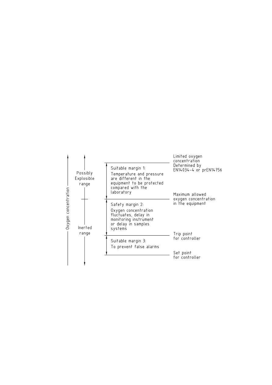
7.3.2 Specification of safe limits
The intention of inerting a process is to prevent the oxygen concentration rising to the point at which the
atmosphere inside the equipment is flammable. This will require that the oxygen content is measured, and is
maintained below the limiting oxygen for combustion (LOC), even during fluctuations of oxygen level during
routine operation. Therefore the normal operating concentration will have to be below this oxygen
concentration. Generally there are four oxygen concentrations to be observed:
limiting oxygen concentration (LOC) determined by EN 14034-4 or prEN 14756;
maximum allowable oxygen concentration (MAOC) in the equipment:
trip point (TP), at which the process controller initiates a shut-down trip;
set point (SP), at which the process controller maintains the oxygen concentration.
The limiting oxygen concentration is determined by test, such as EN 14034-4 or prEN 14756, and is
determined under specified temperature and pressure conditions. As the process may operate at different
temperatures and pressures from those used in the determination of Limiting Oxygen Concentration, it will be
necessary to either apply a suitable margin or determine the LOC at the process conditions. This will give the
maximum allowable oxygen concentration or MAOC. This oxygen level must never be exceeded, as above
this value, the atmosphere would be flammable.
CEN/TR 15281:2006
25
In order to allow adequate variation in oxygen content due to process upsets etc, there will have to be a
suitable safety margin between the MAOC and the Trip Point. Any alarms or trips will operate at the Trip Point,
so that the process can be shut down or made safe. There should be sufficient margin between the trip point
and the MAOC to ensure that the process can be shut down or made safe in the time between tripping and
the oxygen concentration reaching the MAOC.
The magnitude of the required safety margin should be determined by a risk assessment similar to that
required for safety critical equipment, as in Clause 8.
In order to prevent spurious trips, consideration should also be given to the response time of the sampling,
monitoring and control system.
Where the oxygen concentration is continuously monitored, a safety margin of at least 2 volume percentage
points below the MAOC should be maintained, unless the MAOC is less than 5 %, in which case the oxygen
concentration should be maintained at no more than 60 % of the MAOC.
Where the oxygen concentration is not continuously monitored, the oxygen concentration should be
maintained at less than 60 % of the MAOC, unless the MAOC is less than 5 %, in which case the oxygen
concentration should be maintained at less than 40 % of the MAOC.
These limiting values are shown in Figure 11 in diagrammatic form.
Figure 11 — Specification of safe limits for control
7.4 Methods
7.4.1 General
There are different methods of determining whether a system is inert. There is direct measurement, where the
actual oxygen concentration is measured using an oxygen sensor, and inferential methods where there is no
direct measurement, but the oxygen concentration is inferred from either actual measurements taken at
various times, or it is determined by calculation, using the equations given for each method of inerting.
CEN/TR 15281:2006

26
7.4.2 Continuous
oxygen
measurement
It is necessary to measure the oxygen concentration at a point or several points that are representative of the
system to be inerted.
Where a gas sampling system is used it needs to be a reliable sampling system to feed the oxygen analyser,
to ensure representative samples are taken.
Where oxygen monitoring is by means of an in situ sensor (i.e. a sensor which is inserted directly into a
process stream or vessel), then it is likely that the sensor will become contaminated and consequently have a
shorter life than expected.
In order to enable reliable oxygen measurement, it will be necessary to ensure that the sample is conditioned
to remove contamination or materials which will cross-sensitise the oxygen analyser.
Provision will be required for maintaining and calibrating the sensor periodically. Where a process is
continuous, it will be necessary to be able to undertake maintenance and calibration without interrupting the
process.
The advantages of continuous oxygen measurement are:
direct measurement of the safety critical parameter and ability to control directly;
minimises inert gas consumption as gas is only used as required;
detects leaks and process upsets.
The disadvantages of continuous oxygen measurement are:
the safety integrity level (SIL) of oxygen sensors may be inadequate on its own to ensure safety and
additional control methods may be required.
sensors can be contaminated with process materials (see Annex A).
7.4.3 Inferential
methods
7.4.3.1 General
The application of indirect methods requires a thorough analysis of the process /plant including process
upsets to ensure that adequate inerting is achieved at all times as there is no direct measurement of the
oxygen level. There are several methods of achieving the inferential methods, each of which has its own
limitations.
7.4.3.2
Periodic oxygen measurement
The oxygen content of the atmosphere is sampled on a regular periodic basis. It is used to calibrate and
confirm that the purging method achieves the required oxygen level – and is used in conjunction with another
control method such as flow or pressure control. The sampling is typically undertaken by hand using a
portable oxygen meter.
7.4.3.3
Sequential oxygen measurement
One oxygen analyser samples a number of items of process equipment in a regular sequence, so that any
deviation from the required level for each sample point is detected when the pre-set sequence takes the
sample. It can be used to control the oxygen concentration directly.
Inherent problems with time delays may make it unsuitable where rapid changes in oxygen level may occur.
CEN/TR 15281:2006

27
7.4.3.4
Pressure control (with/without cycles)
This method operates by controlling the pressures and number of swings (see Annex B). Pressure control is
required to ensure that the maximum and minimum pressures are achieved for every complete swing or cycle.
A suitable control for number of swings depends on complexity of plant or process, and may be manual on
simple single vessel installations. More complex equipment may need an automatic counter and interlocks,
and may require venting at more than one point. The method should to be confirmed by periodic oxygen
measurement to ensure that the required oxygen level is being met at all places.
Once inert conditions have been achieved, the inert atmosphere can be sustained by maintaining an
overpressure providing that air is not introduced during the process operation. However, if air can be
introduced by any means during the process, additional measures will be required to remove it. Note that
where a system cannot be inerted by a pressure swing technique, a flow technique can be used first, with a
small over-pressure being maintained to sustain the inert atmosphere.
7.4.3.5
Flow control (with/without time)
7.4.3.5.1
Establishing inert conditions
A minimum flow rate needs to be monitored and maintained throughout the entire time that the atmosphere is
being inerted. A suitable control for both duration and flow of inert gas depends on complexity of the plant or
process, and a manual system may be adequate for simple processes or plants. Where the plant or process is
complex it may need an automatic interlock which inhibits the operation until both the flow and time have been
completely satisfied.
However the system is controlled, the establishment of inert conditions should to be confirmed by periodic
oxygen measurements.
7.4.3.5.2
Maintaining inert conditions
Once the inert condition has been established, the minimum flow needs to be monitored continuously.
Monitoring flow on the outlet from the plant or process will detect both loss of inert gas and gross leakage, but
the flow meter may become contaminated with process materials carried out with the vented gas stream. It is
essential that air cannot ingress during process upsets, as this would not be detected. Similarly, small leaks
may not be readily detected, and these could present an asphyxiation risk in confined spaces.
8 Reliability
8.1 Demands for safety critical equipment
The definition of the demands for safety critical equipment involves the following steps:
definition of basis of safety for the inerted equipment. This may involve the use of inerting to modify the
probability of the occurrence of flammable atmospheres;
identification of safety critical equipment distinguished from process control equipment as defined in
IEC 61508-1 to IEC 61508-3;
the safety critical equipment should comply with requirements of European Directive 94/9 and should be
covered by a conformity assessment;
a risk assessment shall be carried out in accordance with IEC 61508-1 to IEC 61508-3 or with an
equivalent or higher safety standard, and safety critical equipment shall comply with IEC 61511-1 to
IEC 61511-3 or with an equivalent or higher safety standard.
CEN/TR 15281:2006

28
8.2 Inerting
systems
8.2.1 General
Reliability of inerting systems may vary according to the chosen method of inerting. After the risk assessment
has been carried out on the equipment to be inerted, a decision will need to be taken about the type of inerting
method needed to achieve the acceptable level of reliability required on the plant. This means that the inerting
method will be defined according to the hazards of the process, and this will result in the choice between
direct measurement of oxygen or inferential methods.
8.2.2 Direct oxygen measurement
The direct oxygen measurement reliability is determined by the standards relevant to oxygen measurement
systems (EN 50104).
The reliability of the inerting system based upon direct oxygen measurement is then defined by a risk
assessment for determination of the safe oxygen content in the equipment and standards for oxygen
measurement.
8.2.3 Inferential
methods
For the inferential methods, as they are not always based upon oxygen analysis, reliability depends upon
several factors which should be considered (see 7.4.3).
A risk assessment should be undertaken, as this defines the hazards of the system and the choice of inerting
method that will be applied.
Every method based solely on inert gas flow and time measurement should be monitored with at least some
oxygen measurement during the calibration purge to determine the characteristics of the system. Once the
characteristics of the system are known, then the reliability of the system is determined by the reliability of the
timing and flow measurement, and is covered by safety critical equipment standards specified in 8.1.
Every method based solely on pressure- or vacuum-swing inerting should be monitored with at least some
oxygen measurement during the initial purges to determine the characteristics of the system. Once the
characteristics of the system are known, then the reliability of the system is determined by the reliability of the
recording of the correct pressures and number of cycles, and is covered by safety critical equipment
standards given in 8.1.
The oxygen meter used for the determination of the oxygen concentration on the initial or calibration purge
should comply with the requirements of EN 50104, and should be calibrated using gases of certified known
oxygen concentration, both before and after the calibration purge of the system is undertaken.
9 Personnel and environmental protection
Personnel can be harmed by atmospheres with reduced oxygen concentrations, even a complete cessation of
breathing can result from an inerted atmosphere (e.g. complete removal of oxygen by nitrogen).
When entering a previously inerted plant guidelines on the respective safety requirements have to be
observed. These guidelines can require all or some of the following:
entry permit which outlines the safety measures;
ventilation requirements;
air analysis;
breathing apparatus.
CEN/TR 15281:2006

29
Whenever possible, entry to inerted vessels during normal operation should be prevented by suitable
measures, such as interlocks or procedures. The requirements for personnel protection have to be part of the
information for use.
Further information and guidance on the asphyxiation hazards of inert gases is available in [14] and [16], and
on ventilation requirements for entry into confined spaces in [10].
If inerted systems operate with an overpressure and are located in confined spaces or small rooms, leaks
from the inerted system will release the inerted atmosphere to the surrounding area. The oxygen
concentration in the confined space will be reduced, especially if gases with high density are released (e.g.
carbon dioxide or argon). Therefore inerted systems should be designed as gas tight as possible. Additional
measures might be required, such as ventilation or air analysis to detect leakage. Also, leakage may cause
the formation of an explosive atmosphere external to the system if absolute inerting has not been achieved.
Inerting requires the removal of oxygen from the interior of the vessels and will thus release the atmosphere
from the vessel to the environment. Environmental problems might arise either from process components or
even from the inert gas itself. Some gases are very effective for the inerting of potentially explosive
atmospheres but have an intolerable impact on the environment (e.g. Halons). Therefore the environmental
impact of an inerted system has to be taken into account.
Where inerted gas mixtures are vented to atmosphere suitable methods will be required to avoid external
explosion or propagation of flame into equipment. This may require the fitting of flame arresters, conservation
vents or other suitable equipment. Further advice can be found in [3] and [28].
10 Information for use
In order to maintain the operability and reliability of an inerting system and its monitoring devices, information
for use has to be supplied by the manufacturer. Information for use has to cover all aspects of plant operation
that have been identified to be relevant for the safety of the system in a risk analysis. To undertake a risk
assessment of the system, the following subjects have to be addressed as a minimum:
definition of intended use (substances, temperature, pressures);
conditions for inert gas supply (oxygen concentration, storage, flows);
required control and maintenance to ensure tightness of the plant;
requirements for regular maintenance and calibration of monitoring systems;
personnel protection;
control over modifications or changes to the equipment or process;
detailed records of the original design, modifications, process changes and calibrations should be kept.
CEN/TR 15281:2006

30
Annex A
(informative)
Oxygen monitoring technology
A.1 Introduction
A number of important factors should be taken into account when selecting an oxygen analyser or sensor for
inerting applications.
a. Consideration should be given to the total response time of the complete system (i.e.
response time of the analyser and the sampling system)
b. The oxygen analyser should also measure flow of the gas sample if an extractive sampling
system is employed. The flow alarm should be assigned the same priority as a high oxygen
alarm.
c. The analyser should be suitable for the particular process conditions involved. It should also
be designed to prevent particles in the gas sample hindering the flow of sample gas to the
sensor.
d. The analyser should not be subject to background gas interference. It should also be capable
of operating over the required temperature and pressure ranges of the process.
e. The material of construction of the analyser and its components should be suitable for the
application (i.e. stainless steel, Hastelloy, etc.)
f. Consideration should be given to the potential for an adverse reaction between the gases
being sampled and active materials of the sensor such as aqueous electrolytes and the
electrodes.
It is not possible to make statements of validity regarding the optimum type of oxygen analyser. Consideration
should also be given to constituents of the gas sample and its effect on the measurement device. Preferably,
the best instrument for the application in question should be selected in co-operation with the supplier. The
following methods are the most commonly employed principles of oxygen monitoring.
A.2 Electrochemical oxygen sensor based analysers
A.2.1 General
Electrochemical oxygen sensors are divided into two different technologies/categories namely:
percentage by volume;
and
partial pressure oxygen sensor.
All electrochemical sensors operate on the principle of having an anode, cathode and electrolyte where an
output/emf is generated proportional to the percentage of oxygen present. A variety of electrolytes are
available to allow the user the selection of the best sensor for their particular process. Electrochemical
sensors when exposed to oxygen are consuming devices and as such have a finite operational life. This is
typically twelve months after which either the sensor is replaced, or rebuilt in the case of some partial pressure
CEN/TR 15281:2006

31
sensors. The raw output signal from these sensors is generally very low and requires
amplification/linearisation prior to display. They are insensitive to shock/vibration and are not position sensitive.
They also have a limited temperature range and normally require a sampling system, particularly if used on
high temperature or pressure applications. The typical failure mode of an electrochemical fuel cell is to zero
and if used on applications with low oxygen concentrations the analyser should have a method of detecting
the difference between a low oxygen concentration and a failed sensor.
If the sensor is employed directly in the process (without an extractive sampling system) the presence of
solvent vapours and particulates in the gas sample will lead to a fouling of the gas sensor and potential to fail
to danger. There is also a potential for a shortening of the sensor life due to drying out of the electrolyte.
By virtue of electrochemical sensor design they lend themselves to their use in hazardous areas by being
available certified intrinsically safe.
A.2.2 Percentage by volume oxygen sensor
As its name implies these sensors respond solely to the changes in oxygen concentration to which it is
exposed. This unique design of these sensors using a capillary sensing technology makes them suitable for
use on process applications where varying pressures and flows are present. These cells do not require a
polarising voltage and as such have an inherent zero. Their characteristics are:
not sensitive to pressure fluctuations;
simplest to calibrate as no zero gas is required;
intrinsically safe sensors available;
not affected by shock and vibration;
fail to danger by giving zero output;
typically sensor life is one year.
A.2.3 Partial pressure oxygen sensor
Partial pressure sensors are divided into two categories namely Fixed Membrane Fuel Cell Types and
Polarographic Rechargeable Type Sensors. As the generic name implies these sensors measures the partial
pressure of oxygen and as such are sensitive to pressure variations, so these sensors are not suitable for use
on in-situ installations. When these sensors have expired the fuel cell type require complete replacement
while the polarographic sensor require new membrane and a recharge of the electrolyte. The polarographic
sensor requires a polarisation voltage to activate the sensor. These sensors should be calibrated at the same
pressure as that to which they will be exposed on the measurement application. Their characteristics are:
sensitive to pressure fluctuation;
zero gas required;
intrinsically safe sensors available;
not affected by shock and vibration;
fails to danger by giving zero output;
typically sensor life is six to twelve months.
The electrochemical cell (fuel cell) is the measurement method most frequently employed. They tend to be
relatively unaffected by background gases and are deemed to be robust on chemical applications. However,
they also have a limited temperature range and require a sampling system if used on high temperature or
pressure applications. The typical failure mode of an electrochemical fuel cell is to zero and if used on
applications with low oxygen concentrations the analyser should have a method of detecting the difference
between a low oxygen concentration and a failed sensor. If the sensor is employed directly in the process
CEN/TR 15281:2006

32
(without an extractive sampling system) consideration should be given to the presence of solvent vapours and
particulates in the gas sample as it can lead to fouling of the gas sensor.
A.2.4 Zirconium oxide sensor
This sensor operates a principal of that of an electrochemical sensor with an anode and cathode (collector) on
either side of a Zirconium tube. The tube is then heated to a temperature in excess of 550 °C. A polarising
voltage is applied across the tube, which creates a signal proportional to the partial pressure of oxygen
presented to the inner surface of the tube. The design of these sensors can be varied to suit the measurement
range required and this can vary from parts per Trillion to 100 % Oxygen. These instruments can operate over
a very wide range of oxygen concentrations (PPM up to 100 % oxygen) and have a very fast speed of
response. These sensors may be used directly at the sample point: however, the presence of particulate in
the gas sample may lead to a fouling of the gas sensor. They are not suitable for gas samples with high levels
of solvent vapours, as they will react with the sensor and lead to inaccurate measurement. Their
characteristics are:
wide rangeability (ppm to 100 % Oxygen);
fast response time;
not suitable for hydrocarbon vapours;
sensitive to pressure fluctuations;
sensitive to shock and vibration;
zero gas required.
A.2.5 Paramagnetic oxygen analysers
These sensors operate on the principle of the paramagnetic tendencies of oxygen. There are two main types
namely: the Magnetic Dumbbell type and the Thermomagnetic type. These sensors have nominally unlimited
life as they are non-depleting: however this can be reduced if it is contaminated from process gases. This type
of instrument also requires a sampling system if used on high temperature applications. When used on
applications where solvents are present it typically requires heated sample lines and a heated measurement
cell to prevent the solvent condensing. Background gases can also affect its measurement and a strong
interaction exists with nitrogen oxides. Their characteristics are:
fast response;
non depleting sensor;
sensitive to pressure and temperature fluctuations;
sensitive to shock and vibration;
requires zero gas;
sensitive to background gas;
not suitable for in-situ measurement;
no determined failure mode.
CEN/TR 15281:2006

33
Annex B
(informative)
Equations for pressure-swing inerting
B.1 Pressure-swing inerting
The theoretical oxygen content after a given number of pressure and relieve cycles can be calculated by
partial pressures from the equation:
(
)
n
i
O
i
n
P
P
C
C
C
C
−
+
=
2
1
(1)
where:
C
n
= oxygen concentration after n purges
C
i
= oxygen concentration in the inert gas
C
0
= initial oxygen concentration
P
1
= lower purge pressure (absolute)
P
2
= upper purge pressure (absolute)
n
= number of pressure/relieve cycles
Any consistent units may be used in this equation.
Inert gas produced by some methods may contain up to 3 % by volume of oxygen, so is accounted for in the
equation by the C
i
term. However, where the inert gas supply is known to contain substantially no oxygen,
then the value of C
i
becomes zero.
The equation (1) above assumes that the expansion and compression is isothermal, and this will be the case
for most situations. However, where the compression or expansion involves high pressure, or rapid pressure
changes, then the compression or expansion may be adiabatic. Under such conditions the oxygen reduction
will be less than that calculated by equation (1), and the modified equation below should be used.
(
)
k
n
i
O
i
n
P
P
C
C
C
C
−
+
=
2
1
(2)
where k = ratio of specific heat of the gas at constant pressure to constant volume.
NOTE
Selected values of k are given at the end of this annex.
Users should satisfy themselves that the appropriate equation has been selected. Examples of the choice of
equation are given below. In order to calculate the number of purges required to achieve a given oxygen
concentration, the reverse solution to equations (1) and (2) are as follows:
−
−
=
2
1
P
P
log
C
C
C
C
log
n
i
O
i
n
(3)
CEN/TR 15281:2006

34
−
−
=
2
1
P
P
log
C
C
C
C
log
k
n
i
O
i
n
(4)
Typically a system will be pressurised to a minimum of about 1 bar gauge before being relieved to
atmospheric pressure. However, to ensure that the mixing is thorough, it is usually necessary to use at least
two cycles. Where the number of purges (minimum 2) and the required concentration of oxygen are known,
the minimum required pressure ratio (i.e. upper absolute pressure/lower absolute pressure) is given as follows
for equations (1) and (2):
n
i
n
i
O
C
C
C
C
R
1
−
−
=
(5)
n
k
i
n
i
O
C
C
C
C
R
−
−
=
(6)
where:
=
1
2
P
P
R
(7)
EXAMPLE B.1 It is required to inert a 10 m
3
vessel to reduce the oxygen content to less than 5 % v/v, using nitrogen at a
pressure of 2 bar gauge, containing less than 0,1 % v/v oxygen. The gas is fed at a flow of 50 m
3
hr
-1
, and vented at a
similar rate. How many purge cycles are required?
The flow rate of 50 m
3
hr
-1
will pressurise the vessel to 2 bar gauge in about 2/5
th
hour, i.e. 24 minutes. This allows
adequate time for the heat of compression to be dissipated, so the appropriate equation is the reverse solution of
equation (1) in the form of equation (3):
−
−
=
2
1
P
P
log
C
C
C
C
log
n
i
O
i
n
Substituting the values gives:
cycles
.
e
.
i
,
log
,
,
log
n
2
32
1
1
2
1
0
1
0
21
1
0
5
+
+
−
−
=
EXAMPLE B.2 A small vessel of 50 litres is pressurised to 3 bar gauge and de-pressurised in 15 seconds three times
using nitrogen containing 1,5 % oxygen. What is the oxygen content after purging?
The time taken is so short that isothermal conditions are unlikely, so equation (2) is applicable.
(
)
k
n
i
O
i
n
P
P
C
C
C
C
−
+
=
2
1
The value of k for nitrogen is given in International Critical Tables as 1,401, so substituting into equation (2) gives:
(
)
%
,
,
,
C
,
n
502
2
4
1
5
1
21
5
1
401
1
1
=
−
+
=
CEN/TR 15281:2006

35
B.2 Vacuum-swing inerting
Exactly the same equations are used for vacuum swing inerting as are used for pressure-swing inerting. The
use of vacuum-swing inerting is preferred for systems which are unable to take a significant internal pressure,
such as glass vessels, and for complex systems where there are dead-ended branches. However, when
vacuum-swing inerting is used, care will be required to ensure that air does not leak in during the time that the
vessel is under vacuum. Therefore it is recommended that a vacuum leak test is carried out as a part of the
inerting process. When evacuated, the source of the vacuum should be isolated, and the rate of rise of
pressure, J, measured over a period of time. The leak-tightness of the system can be compared to the typical
leak rates provided in Table B.1.
Although a high pressure ratio (‘R’) of over 10 can be obtained easily, it is still recommended that at least two
evacuations are made to ensure that the gases mix properly, and the branches of a system are inerted
properly.
The best procedure is as follows:
evacuate system to the lowest vacuum;
isolate the vacuum system;
monitor the rate of pressure rise of the vacuum;
break vacuum with inert gas.
Typical leak-rates which should be achievable are given in [23], as follows:
Table B.1 — Typical rates of pressure rise for vacuum systems
Pressure rise rate, J
mm Hg min
-1
Operating pressure
mm Hg
Category A*
Category B*
Category C*
1 to 10
0,5
0,2
0,05
10 to 30
1,0
0,5
0,05
30 to 100
2,0
0,5
0,05
*
The various categories are specified as follows:
a) Category A represents common practice and is often adequate;
b) Category B represents better practice, but often needs special attentions on large plants with a large number of
flanges;
c) Category C is appropriate where the ingress of air may be harmful to the process, such as pharmaceutical and
semiconductor
manufacture.
Table B.2 — Selected values of k = C
p
/C
v
for various inert gases
Gas
k at 15 °C, 1 atm
Reference
Argon Ar
1,66
[21]
Carbon dioxide
CO
2
1,304
[21]
Helium He
1,664
[22]
Nitrogen N
2
1,404
[21]
Steam (at 100 °C)
H
2
O 1,324
[21]
CEN/TR 15281:2006

36
Annex C
(informative)
Calculations for flow-through inerting
This method assumes perfect backmixing of the air and the inert gas in the system, i.e. the concentration of
oxygen at all points within the system is the same at any one time and is the same as that of the gas leaving.
The time required can be calculated by setting up a differential equation and integrating, giving the equation:
−
−
=
f
i
O
i
C
C
C
C
Q
V
F
t
n
1
(8)
where:
t
=
time required for purging
F
=
safety factor for purging
V
= system
volume
Q =
inert gas flow-rate
C
f
=
oxygen content after flow purging
C
0
=
initial oxygen content
C
i
=
oxygen content of inert gas
NOTE 1
t, V, and Q should be in consistent units.
The safety factor F has to be used in equation (8) unless the actual oxygen content at various points in the
system is measured. As a minimum, the calculated time should be multiplied by a safety factor of between 2
and 5.
As with pressure and vacuum swing inerting, the calculated value from equation (8) is inferential, so it will be
necessary to monitor the actual oxygen concentration at several points within the system to ensure that the
purging has removed the oxygen.
NOTE 2
If the oxygen content changes much more rapidly than calculated, it is indicative of poor mixing, plug flow, or
stagnation. The oxygen content at several points in the system should be measured to determine the cause before it is
assumed that the whole system is inert.
For non-branched pipe-work, it is likely that plug flow will occur, so the safety factor can be taken as unity. For
a vessel with no branches, a safety factor of 2 would be applicable where the inlet and outlet are diametrically
opposite, and for vessels where the inlet and outlet are not diametrically opposite, a safety factor of 5 would
be used. In systems where the inert gas is injected at high velocity (typically in excess of 10 m s
-1
), the jet
mixing which occurs will allow a reduced safety factor to be used. It is recommended that the oxygen of the
exhausted gas is monitored during the first few purges of a system to confirm the adequacy of the purging and
determine a suitable safety factor.
As an example, a large hopper of 80 m
3
purged with nitrogen injected at 170 m
3
hr
-1
at the bottom, took
75 minutes to reduce the oxygen to 2 % v/v in the gas vented from the top, compared with a theoretical time of
66 minutes, giving a safety factor F of 1,14 (see [4]). Further information on inerting a very large silo with
argon is given in [31].
CEN/TR 15281:2006

37
For calculating the concentration of oxygen after a given purge time at a given purge rate the reverse solution
is used:
(
)
×
−
+
=
V
t
Q
F
C
C
C
C
i
O
i
f
exp
(9)
and similarly, for calculating the flow required to purge in a given time, a different reverse solution is used:
(
)
(
)
−
−
−
=
f
i
O
i
C
C
C
C
t
V
F
Q
n
1
(10)
EXAMPLE C.1 A vessel of 3 m
3
is to be purged with oxygen-free nitrogen to reduce the oxygen content to less than
5 % v/v. The flow rate is 10 m
3
hr
-1
and the gas is injected through a 25 mm bore pipe. How long will the purge take?
As the time is required equation (8) is suitable. The injection velocity is 5,6 m s
-1
, so mixing will be good. Therefore a factor
of two is suitable for F. Substituting in equation (8) gives:
(
)
minutes
52
or
hours
86
0
5
0
21
0
n
1
10
3
2
,
t
=
−
−
=
EXAMPLE C.2 The same vessel as in Example C.1 is to be purged using inert gas containing 2 % v/v oxygen. What flow
of inert gas is required to reduce the oxygen from 21 % v/v to 5 % v/v, assuming the same time for purging?
In this case, equation (10) is applicable, so substituting the values into the equation gives:
(
)
(
)
1
3
hr
m
87
12
5
2
21
2
n
1
86
0
3
2
−
=
−
−
=
,
,
Q
CEN/TR 15281:2006
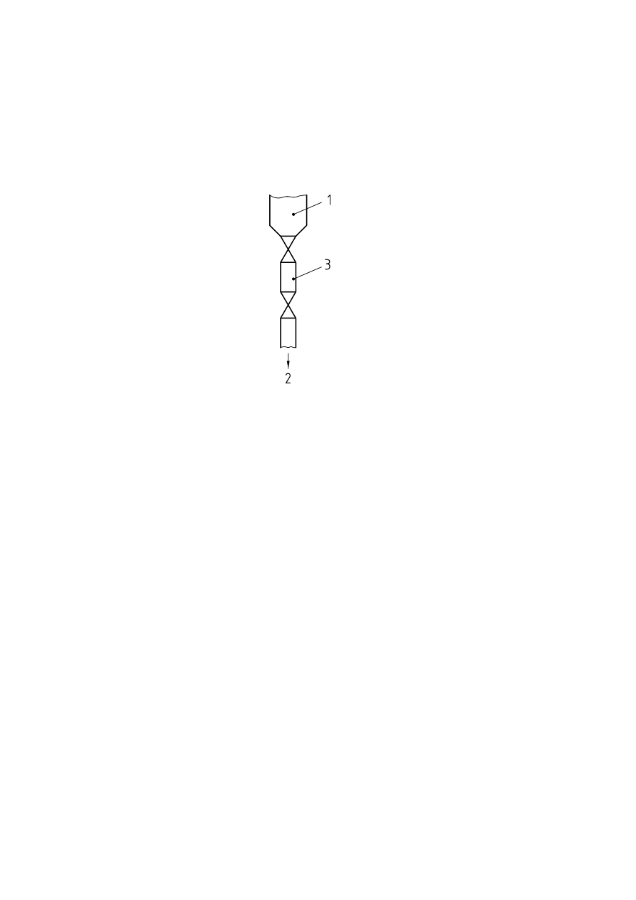
38
Annex D
(informative)
Addition of solids to an inerted vessel using a double valve arrangement
Key
1
=
Solids addition hopper
2 = to
vessel
3
=
Inter-valve space V
v
Figure D.1 — Example of addition of solids for an inerted vessel using a double value arrangement
When adding solids to a vessel which is open to atmosphere, air ingress will occur which will compromise the
inert atmosphere. A double valve arrangement can be used (see Figure D.1) to ensure that the vessel is not
open to atmosphere during the addition.
The upper valve is opened and the solids are added to the inter-valve space, being retained by the lower
valve. The upper valve is closed and the inter-valve space can be purged to minimise the air transferred to the
vessel, although the purging may not remove all the air in the interstices of the powder. In the following
calculation it is assumed that the inert valve space is not purged.
The lower valve is then opened to allow the solids to fall into the vessel. Since some air transfer is inevitable, it
is necessary to calculate the maximum number of transfers that can be made before the oxygen level rises to
the maximum allowable oxygen concentration (MAOC).
CEN/TR 15281:2006

39
For the calculation the following will be assumed:
vessel ullage volume is U
maximum allowable oxygen concentration is C
m
vessel oxygen concentration at the start of the addition is C
n
bulk volume of the solids is V
s
volume of the valve arrangement is V
v
number of additions is n
solids have a void fraction of f.
If the solids have a bulk volume of V
s
and a void fraction of f, then the volume of the air in the solids is
given by the bulk volume multiplied by f, i.e. f x V
s
. If the inter-valve space is not completely filled, then the
volume of air in the space not occupied by the solids is
s
v
V
V
−
. As the air contains 21 % oxygen, then the
volume of oxygen in the inter-valve space for the general case is given by:
(
)
s
s
v
V
f
V
V
×
+
−
21
(11)
This allows for the inter-valve space to be partially filled, so that if the volume of solids added is zero, then the
volume of oxygen added is 21 % of the inter-valve space.
The initial volume of oxygen in the vessel is given by
U
C
n
×
. After the addition, the volume of oxygen in
the vessel is given by:
(
)
U
C
V
f
V
V
n
s
s
v
×
+
×
+
−
21
(12)
and the concentration is given by dividing by the ullage volume, so the vessel oxygen concentration is given
by:
(
)
U
U
C
V
f
V
V
n
s
s
v
×
+
×
+
−
21
(13)
This assumes that all the oxygen in the inter-valve space is transferred to vessel, and that no oxygen remains
in the inter-valve space after the space is isolated from the vessel. This is a simplifying assumption which errs
on the pessimistic. After n additions through the double-valve arrangement, the oxygen added has risen to n
times the addition for one charge of:
(
)
s
s
v
V
f
V
V
×
+
−
21
(14)
i.e.
(
)
s
s
v
V
f
V
V
n
×
+
−
×
21
This should not exceed the maximum permissible oxygen concentration C
m
. Therefore:
(
)
m
n
s
v
C
U
U
C
V
f
V
n
=
×
+
×
−
×
×
21
(15)
Multiplying by U gives:
(
)
U
C
V
f
V
V
n
C
U
n
s
s
v
m
×
+
×
+
−
×
=
×
21
(16)
and collecting terms gives:
(
)
(
)
s
s
v
n
m
V
f
V
V
n
C
C
U
×
+
−
×
=
−
21
(17)
CEN/TR 15281:2006

40
Re-arranging gives:
(
)
(
)
s
s
v
n
m
V
f
V
V
U
C
C
n
×
+
−
−
=
21
(18)
EXAMPLE D.1 It is necessary to charge aliquots of 1,5 litres of a solid of 0,6 void fraction, in a 2,5 litre valve
arrangement, with a start oxygen concentration of 2 % and a maximum of 5 % in a 500 litre ullage space vessel. Firstly, if
inert gas containing 0,3 % oxygen is available at a pressure of 2,2 bar gauge, then to reach 2 % oxygen from 21 % oxygen
would require a number of pressure purges. This can be calculated using the equation:
(
)
(
)
−
−
=
2
1
log
log
P
P
C
C
C
C
n
i
o
i
n
where
C
n
=
oxygen concentration after n purges
C
0
=
initial oxygen concentration
Ci =
oxygen concentration in the inert gas
P
1
=
lower purge pressure (absolute)
P
2
=
upper purge pressure (absolute)
n
=
number of pressure/relieve cycles
So substituting in the values gives the number of purges as:
(
)
(
)
(
)
(
)
149
,
2
5051
,
0
0855
,
1
3125
,
0
log
0821
,
0
log
2
,
2
1
1
0
log
3
,
0
21
3
,
0
2
log
=
−
−
=
=
+
+
−
−
=
n
,
i.e. 3 purges.
The maximum number of additions that can be made before the oxygen rises to an unacceptable level is:
(
)
(
)
59
,
37
9
,
39
1500
5
,
1
6
,
0
5
,
1
5
,
2
21
500
2
5
=
=
×
+
−
−
=
n
,
i.e. 37 additions before a re-inerting of the vessel is required.
EXAMPLE D.2 If the same purge regime is used, but the solids are added in 1,3 litre aliquots with a void fraction of 0,7 in
a 6 litre space, starting at 3 % oxygen and not allowing the oxygen to rise above 5 % in a 100 litre ullage space vessel
would give:
(
)
(
)
69
,
1
81
,
117
200
3
,
1
7
,
0
3
,
1
6
21
100
3
5
=
=
×
+
−
−
=
n
o
r only 1 aliquot.
This shows that the number of permissible additions is maximised by a large ullage space, and by filling the inter-valve
space fully at each addition. Conversely, a small ullage space and partial additions only allow a minimal number of
additions before the inert gas blanket is compromised.
CEN/TR 15281:2006

41
Annex E
(informative)
Addition of solids down a charge-chute to an open vessel
E.1 General
This is the least preferred method of solids addition. If the use of a double-valve arrangement described in
Annex D is impractical due to the quantity of solid to be fed in, or the flow properties make it difficult to add
through a valve, then an open chute could be used. This is, however, an inherently hazardous method due to
the potential for asphyxiation of personnel, and the potential to lose the inert atmosphere with the resultant
risk of an explosion occurring.
E.2 Addition of bags down chutes – general case
If no inert gas were to be used, the oxygen content within the vessel would gradually rise due to the air carried
in with the powder and also due to air diffusing in. With a small nitrogen flow, the oxygen carried in with each
bag of powder will be partially removed in the time interval between each bag being charged, and the oxygen
level will slowly rise with each subsequent bag charged. The oxygen level immediately after the n
th
bag has
been charged is given in a formula due to [26]:
o
*
*
*
n
V
U
t
Q
exp
U
t
n
Q
exp
V
V
+
×
−
−
×
×
−
−
=
1
1
(19)
where:
V
n
=
volume of oxygen in vessel after n
th
bag charged
V
*
=
volume of oxygen in each bag
V
0
=
volume of oxygen in vessel at start
Q =
inert gas flow-rate
n
=
number of bags charged
t
*
=
time between start of successive bags being charged
U =
ullage space in vessel
This is the general case, and can be used for any nitrogen flow and charge frequency. Consistent units should
be used, i.e. volumes in m
3
, times in hours, flows in m
3
hr
-1
, or volumes in litres, times in seconds, flows in
litres
-1
etc.
NOTE
This equation is not rigorous but is conservative. It can predict oxygen levels in excess of 21 %, and should be
limited to levels below 10 % where the errors are tolerable.
CEN/TR 15281:2006

42
E.3 Addition of bags – equilibrium case
The equilibrium case is one in which the oxygen concentration in the vessel is independent of the number of
bags charged, since the inert gas stream removes all the oxygen entering with the powder during the time
elapsing between successive bags. For this simple equilibrium case, the following applies:
(
)
−
×
×
×
−
−
×
=
r
i
b
r
i
*
C
C
U
B
S
K
C
C
C
t
U
Q
n
1
(20)
where:
Q =
volumetric purge rate
U =
vessel ullage space
t
*
=
time between start of successive bags being charged
C
i
=
fractional oxygen concentration in the inert gas
C
b
=
fractional oxygen concentration in air in powder (usually 0,21)
C
r
=
required maximum fractional oxygen concentration in vessel
K =
weight of one bag
S
=
Void fraction of bulk powder (if unknown, assume 0,5)
B
=
Bulk density of powder (if unknown, assume 500 kg/m
3
)
NOTE
Consistent units are required, with both the concentrations and voidage being either fractional or percentages.
E.4 Addition of bags – slug flow case
The third case occurs where a drum or bag is mechanically tipped into the chute, and a “slug” of powder
passes down the chute. This disturbs the steady state oxygen profile in the chute. Under these circumstances,
the air in the chute will require purging out again, and equation (8) for flow-through purging will be applicable.
However, at least five volume changes will be required, so although on the slug breaking through, any excess
pressure in the vessel will immediately vent up the chute and would appear to inert it, only one volume change
will occur. Therefore the chute will still require a further four volume changes to ensure inert conditions are
achieved.
E.5 Location of purge stream where chutes are used
The location of the point of entry of the purging gas stream into a vessel depends on the temperature of the
contents of the vessel. If the vessel contains a liquid which is heated above ambient temperature, then the
inert gas will require injecting into the chute itself immediately above the entry point into the vessel, and
vented up the chute. This will minimise any vapour in the vessel from being carried out of the vessel and up
the chute. If the vapour rises up the chute, then it may condense and the film of liquid will cause the powder to
adhere to the walls of the chute, resulting in poor flow into the vessel. It is also necessary to allow a small
quantity of the inert gas to be purged directly from the vessel, so that there is a net inflow of inert gas from the
chute to the vessel to ensure that any oxygen not displaced from the powder does not accumulate within the
vessel and destroy the inert gas blanket.
If the vessel contains a high boiling point liquid with a low vapour pressure at the prevailing vessel
temperature, then the inert gas feed should be directly into the vessel, and out up the chute. This will ensure
that any oxygen not displaced from the powder in the chute will still be displaced from the vessel. The purge of
CEN/TR 15281:2006

43
inert gas will not carry appreciable amounts of vapour out of the vessel, and hence there will be no problem
with condensation causing powder deposits in the charge chute.
EXAMPLE E.1 A vessel with a gross volume of 6,3 m
3
has 3 m
3
of liquid in it, and forty 25 kg bags of powder are to be
added down a chute over one hour. An oxygen-free inert gas purge of 1 m
3
hr
-1
is fed to the vessel continuously during the
addition. Calculate the oxygen concentration in the vessel after the last bag has been added, assuming that oxygen
concentration in the vessel is 2 % v/v at the start. The maximum allowable concentration is 6,0 % v/v. Is the purge rate
satisfactory for the addition?
Firstly, the appropriate equation to use is equation (19). The ullage space in the vessel is the gross volume less the liquid
volume, i.e. (6,3 - 3) m
3
= 3,3 m
3
. The initial oxygen concentration is 2 % v/v, so therefore the volume of oxygen in the
vessel at the start, V
0
, is 3,3 m
3
x 0,02 = 0,066 m
3
. As the bulk density is unknown, it will be assumed to be 500 kg m
-3
,
and the void fraction will be assumed to be 0,5. The voids will be filled with air containing 21 % v/v oxygen, so this gives a
volume of oxygen in each bag as
00525
0
21
0
5
0
500
25
,
,
,
=
×
×
m
3
. The number of bags, n, is 40; so the time, t, between
additions is 1/40 = 0,025 hours. The flow, Q, is 1 m
3
hr
-1
; and the ullage space is 3,3 m
3
, so substituting into the equation
gives:
066
0
3
3
025
0
1
1
3
3
025
0
40
1
1
00525
0
,
,
,
exp
,
,
exp
,
V
n
+
×
−
−
×
×
−
−
=
and solving results in:
(
)
(
)
066
,
0
00754713
,
0
261423
,
0
00525
,
0
066
,
0
007575
,
0
exp
1
30303
,
0
exp
1
25
005
,
0
+
=
∴
+
−
−
−
−
=
n
n
V
V
Therefore
2478
0
066
0
64
34
00525
0
,
,
,
,
V
n
=
+
×
=
m
3
. As the vessel has an ullage space of 3,3 m
3
, the oxygen
concentration will be
07509
0
3
3
2478
0
,
,
,
=
fraction, or 7,5 %. Therefore the addition will take the oxygen level above the
maximum oxygen concentration, and is not safe. To make the operation safe, the purge rate can be increased or the rate
of addition can be reduced.
EXAMPLE E.2 In the above example, if the addition rate were to be reduced, what would be the maximum addition rate
of the bags to maintain the oxygen at the initial 2 % v/v in the vessel throughout the addition?
Here the correct equation is the equilibrium case, using equation (20). The equation can be re-arranged to calculate t* as:
(
)
−
×
×
×
−
−
×
=
r
i
b
r
i
*
C
C
U
B
S
K
C
C
C
Q
U
t
n
1
Substituting the previous values in the equation yields:
(
)
2525
0
07654
0
3
3
07954
1
1
1
3
3
02
0
0
3
3
500
5
0
25
21
0
02
0
0
n
1
1
3
3
,
,
,
,
n
,
,
,
,
,
,
,
t
*
=
×
=
=
−
×
×
×
−
−
=
hours per bag.
This would then take about 10 hours to charge the solid, and a better solution would be to increase the inert
gas purge. Increasing the inert gas purge Q to 10 m
3
hr
-1
would reduce the time between successive bags
tenfold, so making the total addition time
10
40
2525
0
×
,
= 1,01 hours.
CEN/TR 15281:2006

44
EXAMPLE E.3 As the addition of 40 bags containing 25 kg is labour intensive, it is proposed to add the same 1000 kg of
material supplied in a single flexible intermediate bulk container (FIBC). Is the addition still acceptable?
The addition is now as a slug flow, since the powder will be added in a substantially continuous stream to the vessel. The
initial quantity of oxygen in the vessel is the same at 2 % v/v. However, as the powder is added as a single lot, all the
oxygen within the powder is added, and there is no time between bags to remove the oxygen.
The volume of oxygen added with the powder is calculated the same way, so is given by:
42
0
21
0
5
0
500
1000
,
,
,
=
×
×
m
3
.
The initial volume of oxygen is the same at 3,3 x 0,02 = 0,066 m
3
, so at the end of the addition the total volume of oxygen
in the vessel is 0,42 + 0,066 = 0,486 m
3
, and the concentration has risen
1472
0
3
3
486
0
,
,
,
=
to fraction, or 14,7 % v/v.
Therefore the proposal to add such a large quantity of powder in a single charge is not acceptable.
CEN/TR 15281:2006
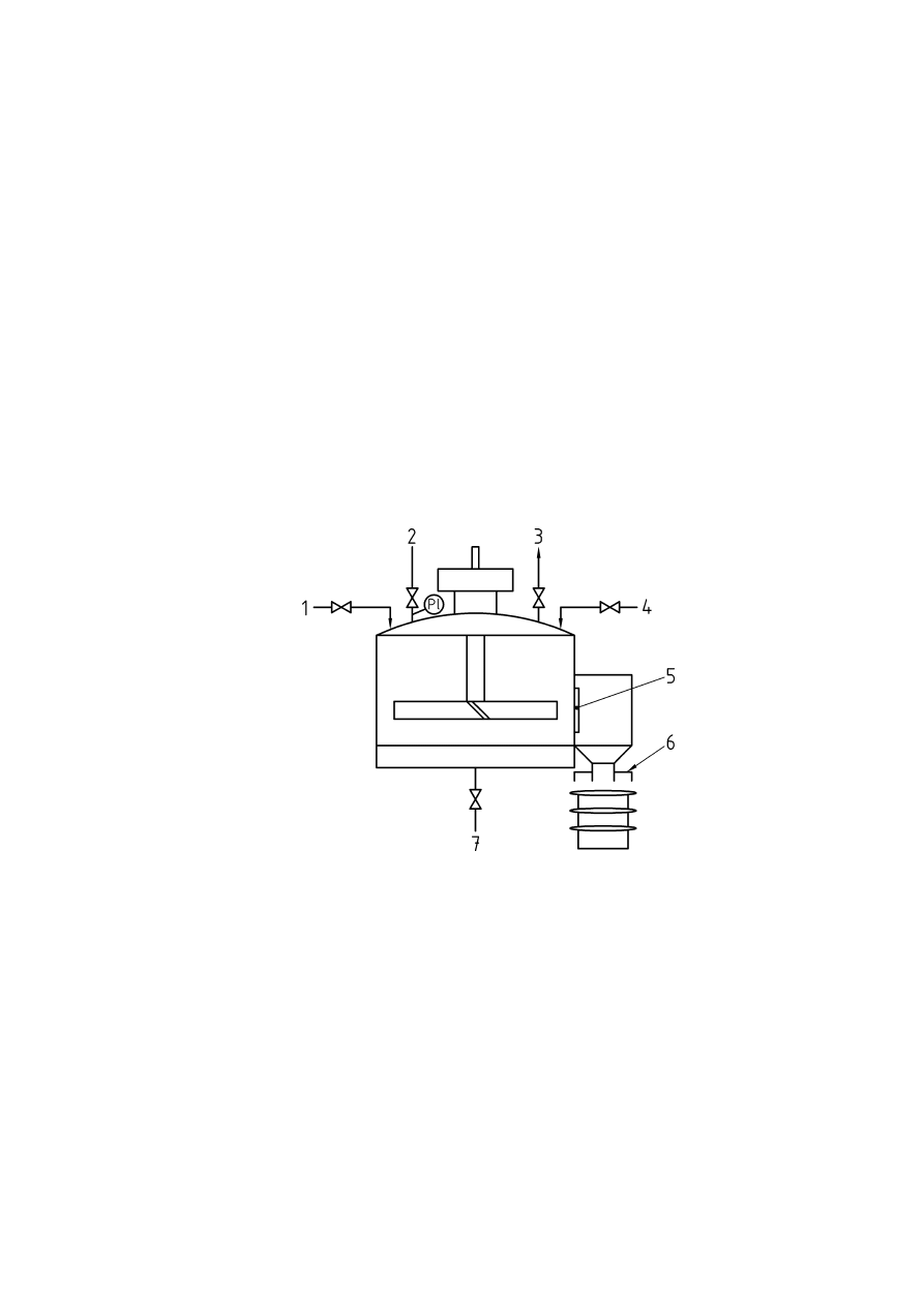
45
Annex F
(informative)
Examples on inerting specific items of process equipment
F.1 General
Each of these examples is for illustrative purposes only, as it is not possible to describe every possible
situation. However, in each of the following examples, the important parts of the equipment and process are
described. This is intended to give an illustration of how inerting might be applied to specific items of
equipment, and to act as a stimulus to adapt it to the situation on a user’s specific equipment. Each example
gives only the basic requirements for inerting based on practical experience, but does not necessarily give a
complete solution to any particular problem.
F.2 Agitated pressure filter/dryer
Key
1
=
Low pressure inert gas feed
2
=
Nitrogen pressure feed
3 =
Vent
4 =
Product
feed
5 =
Discharge
door 6 =
Local
extraction
ventilation
hood
7 =
Filtrates
PI
=
Pressure
Indicator
Figure F.1 — Agitated pressure filter/dryer
This type of filter is a pressure vessel, so can be inerted by the pressure-swing technique (see 7.7.3.4) using
the equations given in Annex B. Once inerted, the slurry passes into the filter, with the mother-liquors passing
through the filter cake, and leaving. Clearly a lute is required on the filtrate exit to avoid air ingress. At the end
of the filtration cycle, inert gas can be blown through the cake to de-liquor it. In the case of a filter/dryer, the
inert gas can be heated and passed through the cake to dry it. The solvent-laden gas is then cooled to recover
the solvent, before being re-heated and passed through the cake again. The gas re-circulation is by means of
a Roots blower or a liquid-ring compressor. It is necessary to ensure that air ingress cannot occur at any time,
and to ensure that this is prevented, the whole system is operated above atmospheric pressure, even at the
suction to the compressor. At the end of the drying cycle, the recirculation is stopped, and the discharge chute
CEN/TR 15281:2006
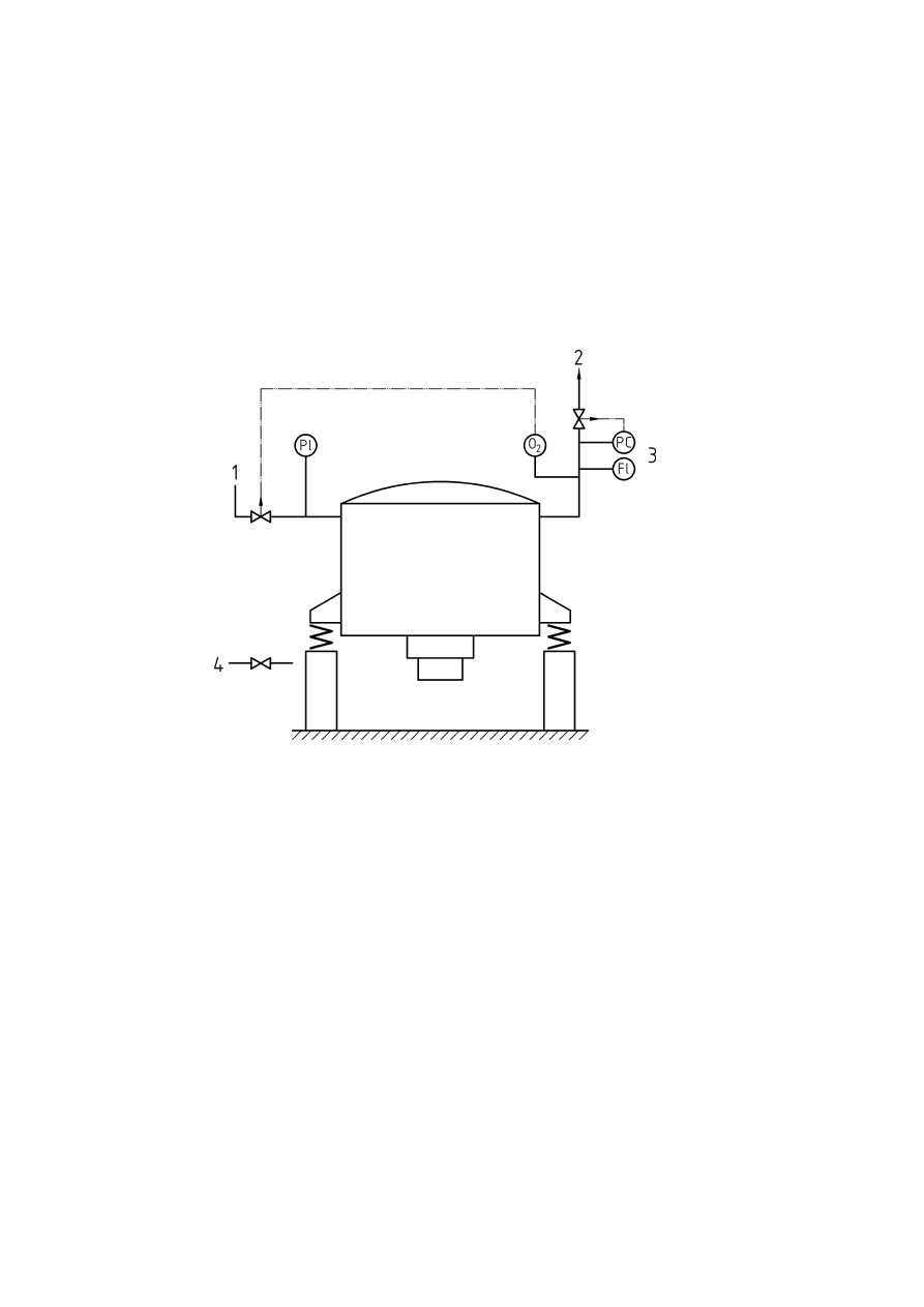
46
opened to allow the cake to discharge. As the agitator could constitute a potential ignition source, air ingress
to the filter should be avoided when the dried solid is discharged. This can be achieved by using a continuous
inert gas purge (see 7.4.3.5), and the flow rate for such a purge can be estimated from the equation (21)
presented in Annex G. To confirm that the inerting technique is correct, it should be subjected to a periodic
check (see 7.4.3.2).
Note that as inert gas may escape to atmosphere when discharging the filter, suitable precautions will be
required to minimise the risk of asphyxiation of personnel in the vicinity (see Clause 9).
F.3 Top discharge centrifuge
Key
1
=
Low pressure inert gas supply
PI =
Pressure Indicator
2 =
Vent
PC
=
Pressure
Controller
3
=
Pressure control or oxygen control
FI =
Flow Indicator
4
=
Inert gas supply to bearings
O
2
= Oxygen
sensor
Figure F.2 — Top discharge centrifuge
This type of centrifuge has an opening lid to allow the basket to be emptied manually. As the centrifuge cannot
withstand a high pressure, it is necessary to use a flow-purging technique to remove the air which inevitably
enters when the basket is emptied. The inert gas flow can be calculated from the equations in Annex C, taking
into account the need to mix the gases properly by injecting at a high enough velocity (see above). Once inert,
the atmosphere should be maintained, by allowing the clarified liquid to drain out through a gas-tight seal lute.
The appropriate method of control of the inert gas depends to a large extent to the risk presented by the liquid
being processed. As the centrifuge has to be opened frequently, air ingress is inevitable at some point in the
cycle, so it will be necessary to use either a pressure controlled and monitored system (see 7.4.3.4) or a
continuous oxygen monitoring system (see 7.4.2), depending on whether the liquid in the equipment is below
or above its flash point during normal operation. With the latter the entire system will be dependant solely on
the reliability of the oxygen analyser, so it will be necessary to ensure that the oxygen analyser system
conforms to the requirements of EN 50104, IEC 61508-1 to IEC 61508-3 and IEC 61511-1 to IEC 61511-3 or
equivalent standards. Further guidance on the safe operation of centrifuges is given in [20].
CEN/TR 15281:2006
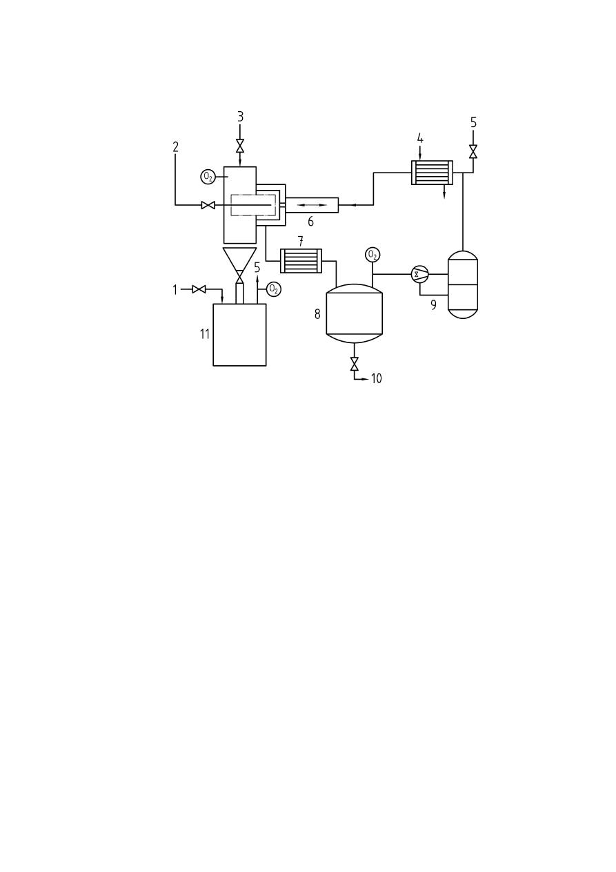
47
F.4 Horizontal pressurised basket centrifuge
Key
1
=
Inert gas feed to purge product container
7
=
Cooler
2 =
Feed 8 =
Filtrates
receiver
3 =
Inert
gas
purge 9 =
Liquid
ring
compressor
4 =
Heater
10
=
Filtrates
5 =
Vent
11
=
Product
container
6 =
Hydraulic
discharge
system
O
2
= Oxygen
sensor
Figure F.3 — Inverting filter horizontal basket centrifuge
This type of centrifuge is generally automatic in operation. The slurry is fed under pressure to the horizontal
basket, and the solid is retained whilst the liquor is collected. After the cake has de-liquored, hot inert gas is
recirculated, in a similar fashion to the pressure filter, until the cake is dry. The solvent evaporated from the
cake is condensed and collected in a suitable receiver. When the cake is dry, it is discharged by inverting the
filter cloth in the basket to displace the cake. In order to retain the inert atmosphere, the discharge must be to
an inerted container such as an Intermediate Bulk Container (IBC), which is pre-inerted. In order to pre-inert
the IBC, a flow through technique is required. The centrifuge then operates with a small over-pressure, and
the entire system will require oxygen monitoring (see 7.4.2). As the IBC is disconnected after filling, removed,
and replaced with an empty container, two oxygen sensors will be required - one to monitor the atmosphere in
the IBC, and one to monitor the remainder of the system. As the condensed solvent has to be removed, a
suitable control system will be required to prevent air ingress whilst the receiver is emptied. As the entire
system will then be dependant solely on the reliability of the oxygen analyser, it will be necessary to ensure
that the oxygen analyser system conforms to the requirements of EN 50104, IEC 61508-1 to IEC 61508-3 and
IEC 61511-1 to IEC 61511-3 or equivalent standards.
CEN/TR 15281:2006
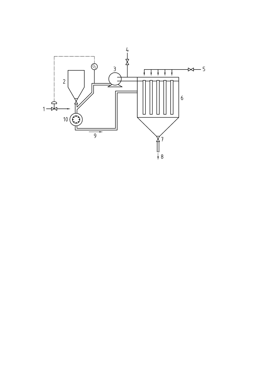
48
F.5 Pinned disc grinding mill
Key
1 =
Inert
gas
feed
6 =
Filter
2 =
Coarse
feed
hopper
7 =
Rotary
valve
3
=
Fan for pneumatic transport
8
=
Milled product
4
=
Excess pressure vent
9
=
Fines suspended in gas stream
5
=
Inert gas reverse jet for filter cleaning
10 =
Mill
O
2
= Oxygen
sensor
Figure F.4 — Pinned disc grinding mill
This type of mill operates at a high speed, and has close-clearance moving parts which could constitute a
source of ignition. When the mill is rotating at its normal operating speed, it acts as a fan, and drives a current
of air through the mill. Hence if the mill is to be inerted, it is necessary to use suitable techniques to prevent
excess air being drawn from the hopper through the mill. Once the material has been ground, it is collected,
typically in a cyclone followed by a filter, or just a filter. The collection system will obviously require inerting
also. Since air ingress is bound to occur as there will be air in the interstices of the powder, a simple flow or
pressure system will not be satisfactory, as the level of oxygen will not be measured. Hence an oxygen
monitoring system will be required which will control the admission of inert gas to dilute the incoming air to
reduce the oxygen to below the maximum allowable oxygen concentration (see 7.4.2).
However, as the entire system will then be dependant solely on the reliability of the oxygen analyser, it will be
necessary to ensure that the oxygen analyser system conforms to the requirements of EN 50104,
IEC 61508-1 to IEC 61508-3 and IEC 61511-1 to IEC 61511-3 or equivalent standards. Since fine dust could
present difficulties with blockage of the sample conditioning system, it may be difficult to satisfy the
requirements of IEC 61511-1 to IEC 61511-3.
CEN/TR 15281:2006
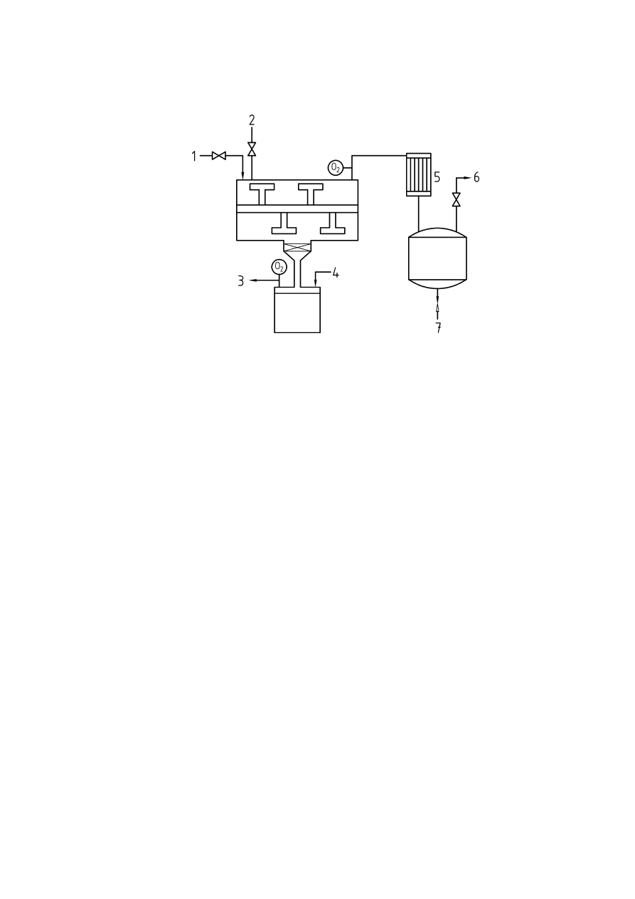
49
F.6 Horizontal paddle dryer
Key
1 =
Feed 5 =
Condenser
2 =
Inert
gas
6 =
Vacuum
3 =
Vent
7 =
Distillate
discharge
4 =
Inert
gas
feed
O
2
= Oxygen
sensor
Figure F.5 — Horizontal paddle dryer
This type of equipment often operates under vacuum, and evaporates the solvent from a solvent-wet paste.
The dry powder will often become electrostatically charged due to the constant agitation, and the large bulk
makes cone discharges a possibility. Therefore the system needs to be operated under an inert gas
atmosphere. As the dryer is a vacuum-rated vessel, inerting by a vacuum-swing technique would be suitable,
using the equations given in Annex B. Once the vacuum has been established, any air in-leakage will
eventually replace the inert atmosphere, and therefore a continuous oxygen analyser will be required
(see 7.4.2). However, if the vessel can withstand an internal explosion, then an inferential technique such as
flow inerting would be acceptable (see 7.4.3.5).
Once the material has been dried, it will have to be discharged. When falling from the dryer vessel into the
collection container, the same problem will occur as in the horizontal centrifuge, in that the container will
initially be filled with air which will have to be displaced before the container is attached to the discharge chute
of the dryer. A flow technique would be suitable for this purpose as it would be a simple system (see 7.4.3.5).
CEN/TR 15281:2006

50
Annex G
(informative)
Prevention of diffusion of air down vent pipes
To prevent the diffusion of air down vent pipes, an equation from [18] can be used.
(
)
(
)
m
D
,
D
,
N
,
e
,
e
m
x
h
,
v
−
−
×
×
×
=
16
0
16
0
64
0
96
0
28
6
022
0
(21)
where:
v
=
purge gas superficial velocity, ft/sec
h
=
distance from end of vent, ft
x
=
required oxygen content, % v/v
m = mol
wt of purge gas
N =
exponent dependant on vent diameter, determined from Figure G.1
D =
vent diameter, inches
NOTE
This equation is dimensionally inconsistent, and is empirical in nature.
This equation is valid for oxygen contents of between 3 % v/v and 6 % v/v. For nitrogen, the exponent N
becomes irrelevant because the molecular weight of nitrogen is 28 and the term involving it becomes unity.
Note that where the inert gas is used to purge out another gas, for example, hydrogen, the mean molecular
weight of the gas purging the oxygen out will be altered, and therefore great care should be taken with the
application of equation (21) under such circumstances, as the required flow of gas will be increased. A second
paper [19] takes into account turbulent conditions at the end of the vent, and the effect of atmospheric
turbulence has been investigated elsewhere (see [11] and [17]).
Where tanks have to remain inert, and a permanent inert gas bleed is used, the flow velocity calculated above
must be maintained through the vent even when there is an outflow from the tank and in-breathing due to
ambient pressure and temperature effects. Guidance on this can be found in [3] and [28]. If the tank is to
‘breathe’, then a suitable inert gas blanket system should be designed, taking into account the various
temperature, pressure and stock movement effects. The necessity of purging the tail pipes of relief devices
such as bursting discs and relief valves depends on the particular application and expert advice should be
sought.
CEN/TR 15281:2006
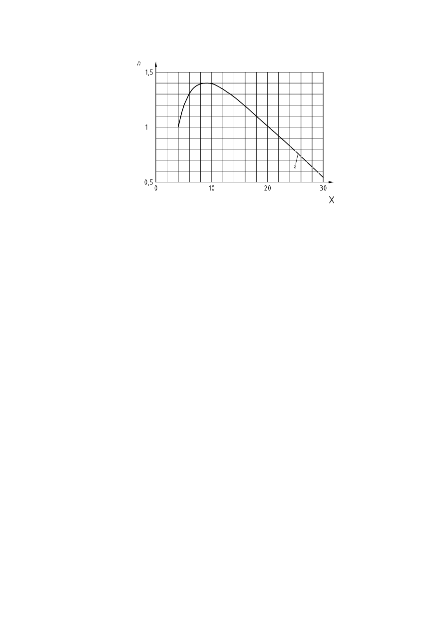
51
Key
X
=
Vent diameter, inches
n = Exponent
a = Extrapolated
Figure G.1 — Value of exponent N in equation [18] for various pipe diameters
CEN/TR 15281:2006

52
Bibliography
[1] EN
1839:2003,
Determination of explosion limits of gases und vapours
[2]
EN ISO 4126-6:2003, Safety devices for protection against excessive pressure – Part 6: Application,
selection and installation of bursting disc safety devices (ISO 4126-6:2003)
[3]
API Standard, API 2000 (1992), American Petroleum Institute, Washington D.C.
[4]
Astbury, G. R. (2001), Explosion Prevention by Inerting, Process Safety and Industrial Explosion
Protection – Part 2 Industrial Explosion Protection, European Safety Management Group e. V., Hamm,
ISBN 3-9807567-1-8
[5]
Astbury, G. R. (1979), Practical Plant Notes – Sampling Lines under Vacuum or Pressure, The
Chemical Engineer, June 1979, p. 481
[6]
Astbury, G. R., & Hooker, P. (2000), Air ingress to nitrogen inerted chutes, I.Chem.E. Symposium
Series No. 147, ISBN 0-85295-429-8
[7] Wiemann,
W. (1984), Einfluss der Temperatur auf Explosionskenngrößen und
Sauerstoffgrenzkonzentrationen, VDI-Bericht 494, pp. 89 - 97, VDI-Verlag GmbH, Düsseldorf
[8]
Bodurtha, F. T. (1980), Industrial Explosion Prevention and Protection, McGraw-Hill Book Company,
ISBN 0-07-006359-1
[9]
Brandes and Möller (2003), Sicherheitstechnische Kenngrößen, Band 1: Brennbare Flüssigkeiten und
Gase (Safety related Properties – Part 1: Flammable Liquids and Gases), Wirtschafysverlag NW,
Bremerhaven, ISBN 3-89701-745-8
[10] BGR
117,
Arbeiten in engen Räumen und Behältern (Measurements to carry out work within confined
spaces and vessels)
[11] Bryce,
S. G., and Fryer-Taylor, R. E. J. (1994), Reducing the purge in hydrocarbon vent stacks,
J. Loss Prev. Proc. Ind., 7, pp. 249-255
[12]
Coffee, R. D., Vogel, P. C., & Wheeler, J. J. (1972), Flammability Characteristics of Methylene
Chloride (Dichloromethane), J. Chem. Eng. Data, 17, 1, pp- 89-93
[13]
Coward, H. F., and Jones, G. W. (1952), Limits of Flammability of Gases and Vapors, U.S. Bureau of
Mines Bulletin 503
[14]
European Industrial Gases Association, Avenue Des Arts 3-5, B-1210, Brussels. (http://www.eiga.org)
IGC Doc 44/00/E Asphyxiation Hazards of Inert Gases.
[15]
Glor, M., & Schwenzfeuer, K. (1996), Einfluss der Sauerstoffkonzentration auf die Mindestzünd-
erenergie von Stäuben, VDI Berichte Nr. 1272, pp. 119-134
[16]
Henderson, Y., & Haggard, H. W. (1943), Noxious Gases, 2nd Ed., Reinhold, New York
[17]
Hooker, P., Astbury, G. R., & Fauré, G. (2001), Air ingress to nitrogen inerted vent pipes, I.Chem.E.
Symposium Series No. 148, ISBN 0-85295-441-7
[18]
Husa, H. W. (1964), How to Compute Safe Purge rates, Hydrocarbon Proc. & Petr. Ref., 43,
pp. 179-182
[19]
Husa, H. W. (1977), Purging Requirements of Large Diameter Stacks, presented at Fall 1977 Meeting
API Fire/Safety Subcommittee, Sept 13-15th 1977, Holiday Inn, San Francisco, USA
[20]
Institution of Chemical Engineers (1987), User Guide for the Safe Operation of Centrifuges, revised
second edition, Institution of Chemical Engineers, Rugby, ISBN 0-85295-218-X
[21]
International Critical Tables, Vol. 5, McGraw Hill Book Company, Inc., p. 80 (1929)
[22]
Lide, D. R. (Ed) (2000), CRC Handbook of Chemistry and Physics, 81st Edition, CRC Press,
ISBN 0-8493-0481-4
CEN/TR 15281:2006

53
[23] E.E.U.A.,
Handbook No 11, Vacuum Producting Equipment, The Engineering Equipment Users
Association, Constable & Company Ltd., London (1961), pp. 40 - 41
[24] Molnárné, Schendler and Schröder (2003), Sicherheitstechnische Kenngrößen – Band
2:
Explosionsbereiche von Gasgemischen (Safety related Properties – Part 2: Explosive Range of Gas
Mixtures), Wirtschafysverlag NW, Bremerhaven, ISBN 3-89701-745-8
[25]
Plumb, K. C. (1979), Practical Plant Notes – Sampling System for Stirred Tank Reactors, The
Chemical Engineer, May 1979, p. 361
[26]
Stockton, P. J. (1987), Private Communication to G. R. Astbury
[27]
Tite, J. P., Greening, K., & Sutton, P. (1989), Explosion hazard of air ingress into flare stacks, Chem.
Eng. Res. Des., p. 67, 373-380
[28] TRbF
20:2000-04;
Technische Regeln für brennbare Flüssigkeiten – Läger (Technical Rules for
Flammable Liquids – Storage)
[29]
VDI 2263 Blatt 2:1992-05; Staubbrände und Staubexplosionen – Gefahren, Beurteilung,
Schutzmaßnahmen; Inertisierung (Dust Fires and Explosions – Hazards, Assessment, Protective
Measures)
[30]
White, P., and Smith, S. (1962), Inert Atmospheres, Butterworth, London
[31]
Woowat, A., Kempsell, I., & Windebank, S. (2003), Lessons learnt from fitting an inert gas blanketing
facility to an existing storage silo, I.Chem.E. Symposium Series No. 149, ISBN 0-85295-459-X
[32]
Zabetakis, M. G. (1965), Flammability Characteristics of Combustible Gases and Vapors, U.S. Bureau
of Mines Bulletin 627
[33] CLC/TR
50404:2003, Electrostatics – Code of practice for the avoidance of hazards due to static
electricity.
CEN/TR 15281:2006

PD CEN/TR
15281:2006
BSI
389 Chiswick High Road
London
W4 4AL
BSI — British Standards Institution
BSI is the independent national body responsible for preparing
British Standards. It presents the UK view on standards in Europe and at the
international level. It is incorporated by Royal Charter.
Revisions
British Standards are updated by amendment or revision. Users of
British Standards should make sure that they possess the latest amendments or
editions.
It is the constant aim of BSI to improve the quality of our products and services.
We would be grateful if anyone finding an inaccuracy or ambiguity while using
this British Standard would inform the Secretary of the technical committee
responsible, the identity of which can be found on the inside front cover.
Tel: +44 (0)20 8996 9000. Fax: +44 (0)20 8996 7400.
BSI offers members an individual updating service called PLUS which ensures
that subscribers automatically receive the latest editions of standards.
Buying standards
Orders for all BSI, international and foreign standards publications should be
addressed to Customer Services. Tel: +44 (0)20 8996 9001.
Fax: +44 (0)20 8996 7001. Email: orders@bsi-global.com. Standards are also
available from the BSI website at http://www.bsi-global.com.
In response to orders for international standards, it is BSI policy to supply the
BSI implementation of those that have been published as British Standards,
unless otherwise requested.
Information on standards
BSI provides a wide range of information on national, European and
international standards through its Library and its Technical Help to Exporters
Service. Various BSI electronic information services are also available which give
details on all its products and services. Contact the Information Centre.
Tel: +44 (0)20 8996 7111. Fax: +44 (0)20 8996 7048. Email: info@bsi-global.com.
Subscribing members of BSI are kept up to date with standards developments
and receive substantial discounts on the purchase price of standards. For details
of these and other benefits contact Membership Administration.
Tel: +44 (0)20 8996 7002. Fax: +44 (0)20 8996 7001.
Email: membership@bsi-global.com.
Information regarding online access to British Standards via British Standards
Online can be found at http://www.bsi-global.com/bsonline.
Further information about BSI is available on the BSI website at
http://www.bsi-global.com.
Copyright
Copyright subsists in all BSI publications. BSI also holds the copyright, in the
UK, of the publications of the international standardization bodies. Except as
permitted under the Copyright, Designs and Patents Act 1988 no extract may be
reproduced, stored in a retrieval system or transmitted in any form or by any
means – electronic, photocopying, recording or otherwise – without prior written
permission from BSI.
This does not preclude the free use, in the course of implementing the standard,
of necessary details such as symbols, and size, type or grade designations. If these
details are to be used for any other purpose than implementation then the prior
written permission of BSI must be obtained.
Details and advice can be obtained from the Copyright & Licensing Manager.
Tel: +44 (0)20 8996 7070. Fax: +44 (0)20 8996 7553.
Email: copyright@bsi-global.com.
Wyszukiwarka
Podobne podstrony:
The American Society for the Prevention of Cruelty
The American Society for the Prevention of Cruelty
A software authentication system for the prevention of computer viruses
Interventions for the prevention of falls in older adults
Clinical trials on onabotulinumtoxinA for the treatment
Advisory Committee on the Framework Convention for the Protection of National Minorities Second Opin
Smarzewska, Sylwia; Ciesielski, Witold Application of a Graphene Oxide–Carbon Paste Electrode for t
Resolution CM ResCMN(2008)1 on the implementation of the Framework Convention for the Protection of
Advisory Committee on the Framework Convention for the Protection of National Minorities Opinion on
[Pargament & Mahoney] Sacred matters Sanctification as a vital topic for the psychology of religion
International Convention for the Safety of Life at Sea
Broad; Arguments for the Existence of God(1)
ESL Seminars Preparation Guide For The Test of Spoken Engl
Kinesio taping compared to physical therapy modalities for the treatment of shoulder impingement syn
GB1008594A process for the production of amines tryptophan tryptamine
Popper Two Autonomous Axiom Systems for the Calculus of Probabilities
Anatomical evidence for the antiquity of human footwear use
The Reasons for the?ll of SocialismCommunism in Russia
więcej podobnych podstron