1
Service Training
Self-study Programme 388
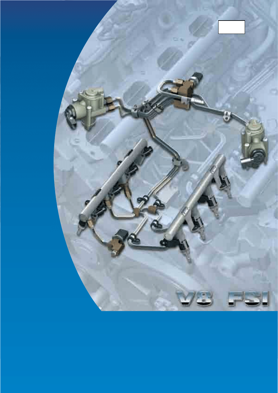
The 4.2l V8 4V FSI Engine
Design and Function
2
The self-study programme shows the design and
function of new developments.
The contents will not be updated.
For current testing, adjustment and repair
instructions, refer to the relevant service literature.
The 4.2l V8 4V FSI engine is a further example of
direct petrol injection. It replaces the 4.2l V8 5V
engine in the Touareg. Apart from the common
cylinder bank angle of 90°, the two engines are no
longer comparable.
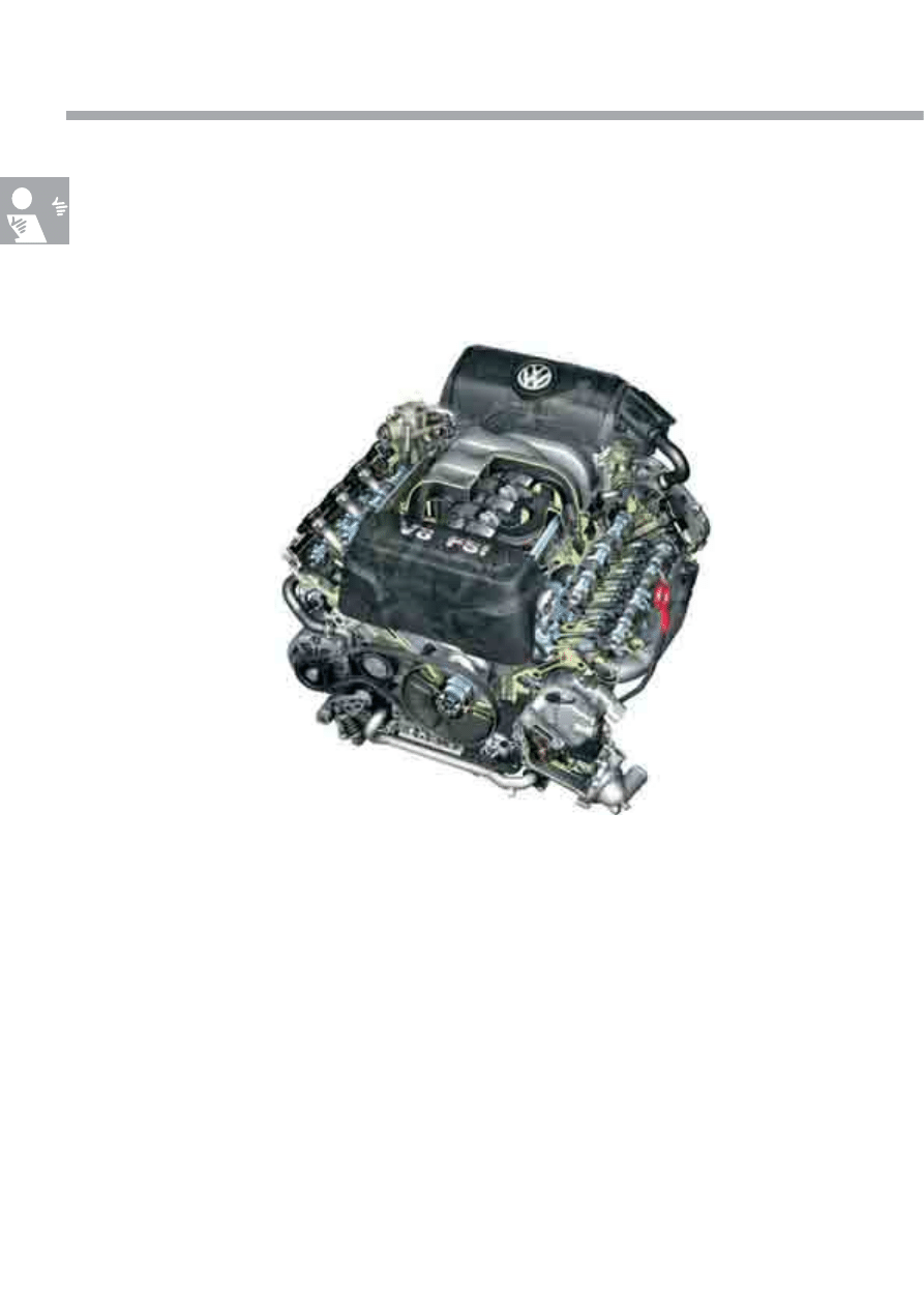
With output of 257 kW and 440 Nm of torque, the
engine offers very good performance, outstanding
dynamics and a high level of ride comfort. This engine
has already been launched in the Audi Q7.
NEW
Important
Note
This self-study programme provides information on the design and function of this new engine
generation.
S388_002

3
Introduction . . . . . . . . . . . . . . . . . . . . . . . . . . . . . . . . . . . . . . . . . . . . . . . . . . 4
Technical features . . . . . . . . . . . . . . . . . . . . . . . . . . . . . . . . . . . . . . . . . . . . . . . . 4
Technical data . . . . . . . . . . . . . . . . . . . . . . . . . . . . . . . . . . . . . . . . . . . . . . . . . . 5
Engine mechanics . . . . . . . . . . . . . . . . . . . . . . . . . . . . . . . . . . . . . . . . . . . . . 6
Chain drive . . . . . . . . . . . . . . . . . . . . . . . . . . . . . . . . . . . . . . . . . . . . . . . . . . . . . 6
Ancillary unit drive . . . . . . . . . . . . . . . . . . . . . . . . . . . . . . . . . . . . . . . . . . . . . . . 7
Intake system . . . . . . . . . . . . . . . . . . . . . . . . . . . . . . . . . . . . . . . . . . . . . . . . . . . 8
Cylinder block . . . . . . . . . . . . . . . . . . . . . . . . . . . . . . . . . . . . . . . . . . . . . . . . . . 10
Cylinder heads . . . . . . . . . . . . . . . . . . . . . . . . . . . . . . . . . . . . . . . . . . . . . . . . . 11
Oil supply . . . . . . . . . . . . . . . . . . . . . . . . . . . . . . . . . . . . . . . . . . . . . . . . . . . . . 12
Crankcase breather and ventilation system . . . . . . . . . . . . . . . . . . . . . . . . . 14
Cooling circuit . . . . . . . . . . . . . . . . . . . . . . . . . . . . . . . . . . . . . . . . . . . . . . . . . 17
Fuel system . . . . . . . . . . . . . . . . . . . . . . . . . . . . . . . . . . . . . . . . . . . . . . . . . . . . 18
Exhaust system . . . . . . . . . . . . . . . . . . . . . . . . . . . . . . . . . . . . . . . . . . . . . . . . . .19
Engine management . . . . . . . . . . . . . . . . . . . . . . . . . . . . . . . . . . . . . . . . . . 22
System overview . . . . . . . . . . . . . . . . . . . . . . . . . . . . . . . . . . . . . . . . . . . . . . . 22
CAN networking . . . . . . . . . . . . . . . . . . . . . . . . . . . . . . . . . . . . . . . . . . . . . . 24
Sensors . . . . . . . . . . . . . . . . . . . . . . . . . . . . . . . . . . . . . . . . . . . . . . . . . . . . . . . 25
Actuators . . . . . . . . . . . . . . . . . . . . . . . . . . . . . . . . . . . . . . . . . . . . . . . . . . . . . 30
Functional diagram . . . . . . . . . . . . . . . . . . . . . . . . . . . . . . . . . . . . . . . . . . . . . 34
Service . . . . . . . . . . . . . . . . . . . . . . . . . . . . . . . . . . . . . . . . . . . . . . . . . . . . . 38
Test yourself . . . . . . . . . . . . . . . . . . . . . . . . . . . . . . . . . . . . . . . . . . . . . . . . . 39
Contents
4
The 4.2l V8 4V FSI engine is the most recent example of a direct petrol injection engine from Volkswagen. It is the
successor of the 4.2l V8 5V engine with intake manifold injection. In addition to direct petrol injection, certain new
features have been implemented in both the engine management and in the engine's mechanical systems.
Introduction
Special technical features
Technical features
●
Bosch Motronic MED 9.1.1
●
Direct petrol injection
●
Homogenous mode (Lambda 1)
●
Double injection catalytic converter heating
●
Electronic throttle
●
Two hot film air mass sensors
●
Electronically regulated cooling system
●
Adjustment of the variable intake manifold and
intake manifold flap change-over by means of an
electric motor
●
Continuous inlet and exhaust camshaft timing
adjustment
●
Two-stage magnesium variable intake manifold
with integrated intake manifold flap change-over
●
Two-piece cylinder block
●
Flywheel-end chain drives for camshafts and
ancillary units
●
Spur gear drive for ancillary units
●
Secondary air system
S388_003
5
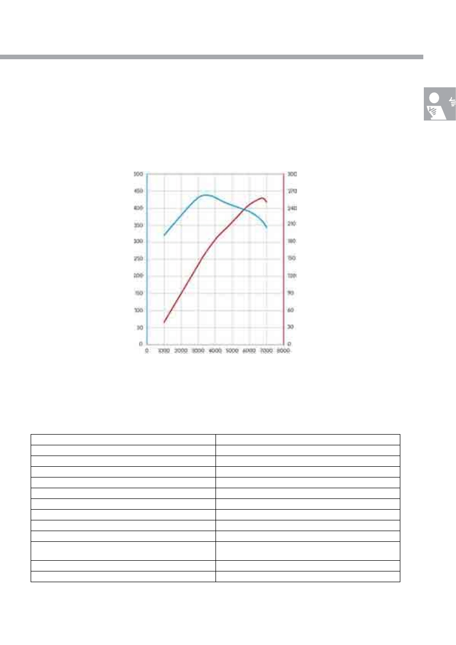
Technical data
Torque and output diagram
Technical data
Engine code
BAR
Type
8 cylinders with 90° V angle
Displacement in cm³
4163
Bore in mm
84.5
Stroke in mm
92.8
Valves per cylinder
4
Compression ratio
12.5:1
Maximum output
257 kW at 6800 rpm
Maximum torque
440 Nm at 3500 rpm
Engine management
Bosch Motronic MED 9.1.1
Fuel
Premium plus unleaded RON 98 or
premium unleaded RON 95
Exhaust gas treatment
4 catalytic converters, 4 lambda probes, secondary air system
Emissions standard
EU 4
Nm
kW
rpm
S388_004
Po
w
e
r [
k
W
]
To
rq
u
e
[
N
m
]
6
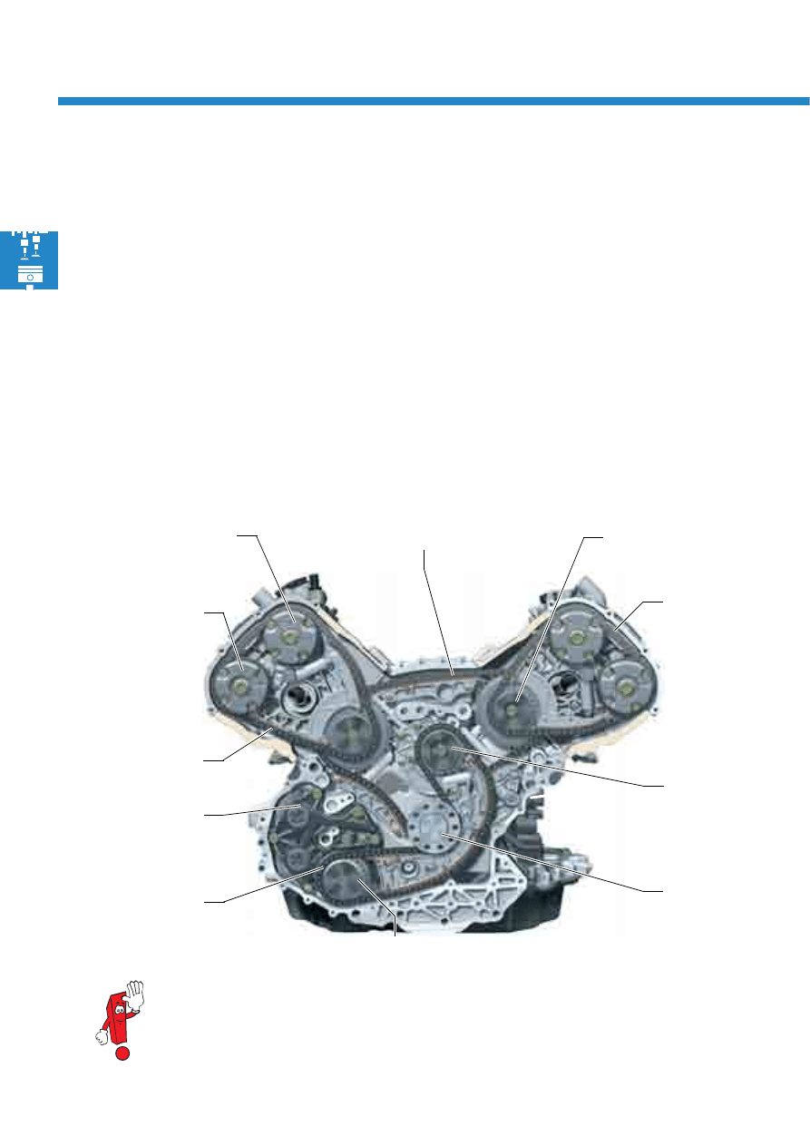
Engine mechanics
Crankshaft
Drive chain sprocket for
camshaft timing chain
Camshaft
adjuster for
exhaust
camshaft
Drive chain sprocket for
ancillary drives
Chain drive D
Guide chain
sprocket for
ancillary drives
Camshaft adjuster for
inlet camshaft
Chain drive B
Chain drive
S388_005
The chain drive is maintenance-free and is designed for use throughout the engine's service life. In the
event of repairs, please note the information in ELSA under all circumstances.
Chain drive C
Chain drive A
Spur gear drive
In the 4.2l V8 4V FSI engine, the camshafts and ancillary units are driven via a total of four roller chains on two
levels. The chain drive has the advantage that it is maintenance-free and reduces the length of the engine.
The crankshaft drives the two drive gears for the camshaft timing chains via chain drive A. In turn, these two drive
gears drive the camshaft adjusters for the exhaust and inlet camshafts via chain drives B and C.
In chain drive D, the crankshaft drives the drive chain sprocket for ancillary drives. This is used to drive the spur
gear for the ancillary units.
The chains are tensioned via hydraulic spring tensioners.
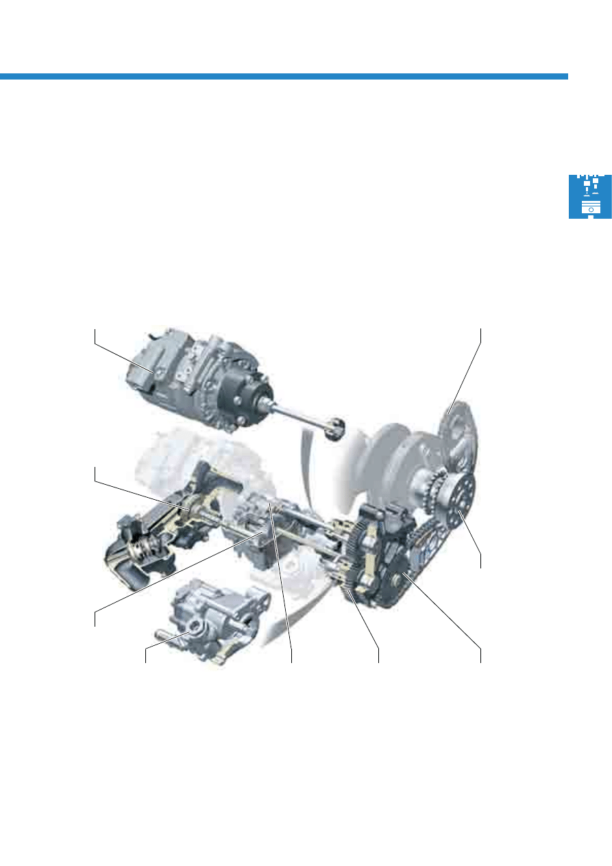
7
Air conditioner
compressor
Spur gear drive
Drive chain sprocket
for ancillary drives
Gear module
Power steering
pump
Crankshaft
Chain drive D
Coolant pump
S388_006
Oil pump
Ancillary unit drive
The ancillary units are driven by the crankshaft via chain drive D, a spur gear drive, a gear module and four
intermediate shafts. The oil pump, the coolant pump, the power steering pump and the air conditioner compressor
are driven.
The gear module is used to adapt the rotational speed and therefore the delivery rate of the coolant pump and the
oil pump.
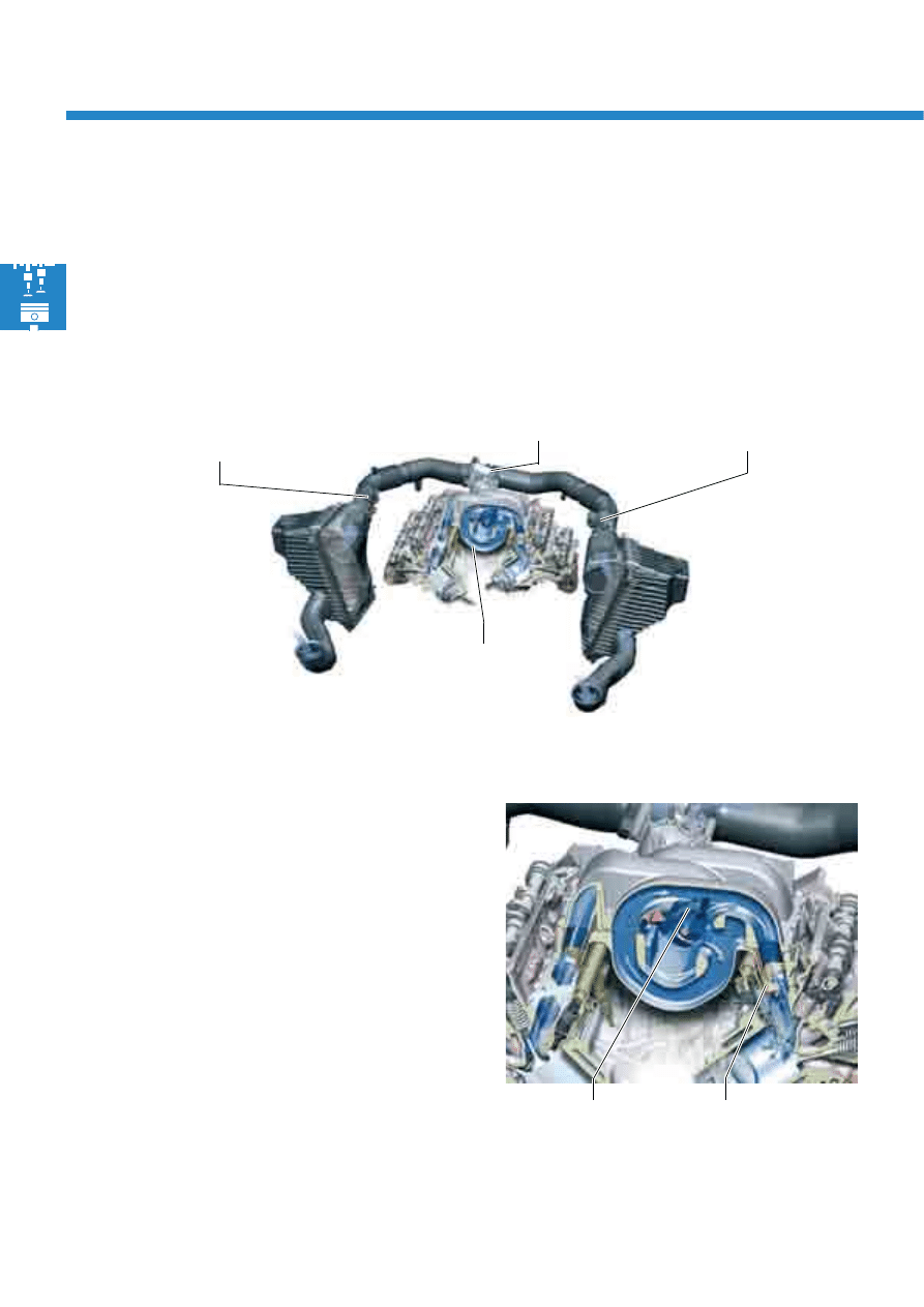
8
S388_007
Throttle valve
module J338
Air mass meter G70
Intake air temperature sender G42
cylinder bank 1
Variable intake
manifold
Air mass meter G246
cylinder bank 2
Intake manifold
The two-stage variable intake manifold is
manufactured from die-cast magnesium.
It contains the change-over flaps for the variable
intake manifold and the intake manifold flaps for
intake manifold flap change-over.
Engine mechanics
Intake system
As in the 4.2l V8 5V engine fitted in the Touareg, the fresh air intake system is designed with two branches, and
therefore reduces pressure losses.
Both intake tracts are brought together upstream of a common throttle valve module. To determine the intake mass
of fresh air as accurately as possible, each intake tract is equipped with a hot film air mass meter.
Change-over flap
Intake manifold flaps
S388_008
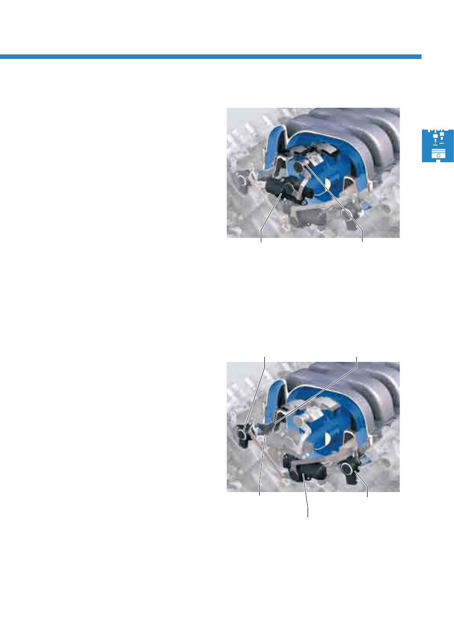
9
Variable intake manifold
In the variable intake manifold, switching between the
short and the long intake manifold is carried out
depending on a performance map.
- In the lower engine speed range, switching takes
place to the torque position (long intake manifold)
- In the upper engine speed range, switching takes
place to the output position (short intake manifold)
The change-over flaps are actuated by the variable
intake manifold motor. If this is actuated by the
engine control unit, it adjusts the selector shafts, which
are connected together via a linkage system, and the
change-over flaps located on these.
The change-over flaps are equipped with a sealing
lip, in order to ensure that the long intake manifold
remains leak-tight in the torque position.
Intake manifold flap change-over
The intake manifold flaps are installed in the two
intake manifold lower sections. They are actuated,
depending on load and engine speed, by an intake
manifold flap motor and two linkage systems.
- At low load and engine speed, they are actuated
and close off the lower section of the intake ports.
This results in cylinder-shaped air flow into the
cylinder.
- At high load and engine speed, they are not
actuated, and lie flush against the surface of the
intake port in order to avoid flow losses.
Due to emission-relevant reasons, the positions of the
intake manifold flaps are monitored by two intake
manifold flap potentiometers.
Variable intake
manifold motor V183
Selector shaft with
change-over flaps
S388_009
Intake manifold
flap
motor
V157
Intake manifold
flaps
Intake manifold flap
potentiometer G336
S388_010
Intake manifold flap
potentiometer G512
Separating plate
10
Engine mechanics
S388_012
Piston skirt
Crankshaft
Piston crown
Cracked connecting rod
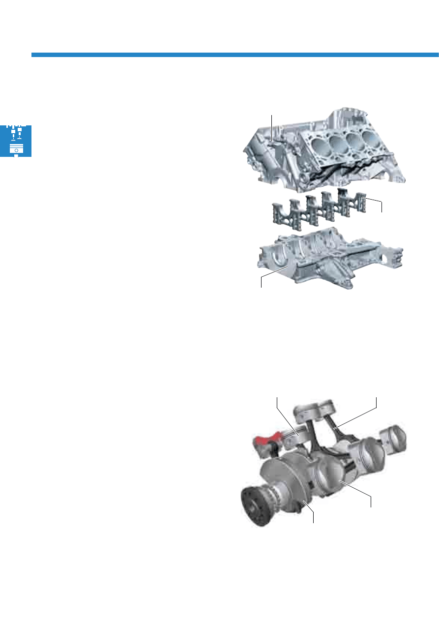
The cylinder block is manufactured from an
aluminium-silicon alloy by means of low-pressure
gravity die casting. It is characterised by high
strength, very low cylinder warming and good
thermal dissipation.
To obtain the narrowest cylinder webs possible,
cylinder liners have been omitted.
Final cylinder bore surface machining is carried out in
a three-stage honing and exposure process. During
this process, the aluminium is separated out from the
surface and the silicon is exposed in the form of
minute and particularly hard particles. These finally
form the wear-resistant contact surface for the pistons
and the piston rings.
The ladder frame is manufactured from an
aluminium-silicon alloy by means of die casting.
Cast-in bearing caps manufactured from cast iron
with nodular graphite reinforce the ladder frame and
absorb the majority of the flow of force. Due to their
thermal expansion, which is lower than that of
aluminium at high temperatures, they simultaneously
limit main bearing clearance.
The ladder frame design with bearing caps offers
high longitudinal and transverse stiffness.
Crankshaft drive
Cylinder block
Cast-in bearing
cap
Cylinder block
The crankshaft is manufactured from high-quality
tempered steel, and is supported at five points.
The connecting rods are manufactured using the
cracking method.
The pistons are forged due to reasons of strength. The
piston crown has been adapted to the combustion
process involved in FSI technology, and supports the
cylindrical flow of air in the cylinder. The piston skirts
are coated with Ferrostan, a contact layer which
contains iron. This prevents direct contact between the
aluminium surfaces of the pistons and the cylinder
contact surfaces, as this increases wear.
S388_011
Ladder frame
11
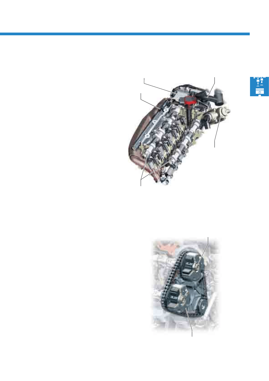
Cylinder heads
The 4-valve cylinder head is manufactured from an
aluminium alloy. This material guarantees very good
thermal conductivity with good strength values.
- The separating plates for intake manifold flap
change-over are installed in the intake ports.
- The injectors are fitted on the intake side in the
cylinder head.
- The high-pressure fuel pumps are driven via dual
cams on the inlet camshafts.
- The cylinder head cover is made of plastic and
contains a labyrinth oil separator.
- The camshafts are fully-assembled and are driven
via a chain drive.
- The exhaust valves are filled with sodium. This
reduces the temperature at the valve by approx.
100°C.
S388_013
Crankcase breather
system
High-pressure fuel
pump with fuel
metering valve
Fully-assembled
camshaft
Hall sender
Cylinder head
cover
S388_014
Inlet adjuster
Exhaust adjuster with
return spring
Camshaft adjustment system
The gas exchange processes in the engine's
combustion chamber exert a significant influence on
output, torque and pollutant emission. The camshaft
adjustment system allows these gas exchange
processes to be adapted to the engine's relevant
requirements. Camshaft adjustment is carried out
continuously via vane adjusters, and equates to a
maximum of 42°. The position of the camshafts are
detected by means of four Hall senders.
When the engine is stationary, the vane adjusters are
locked using a spring-loaded locking pin.
The inlet camshafts are set to the "retarded" position
and the exhaust camshafts to the "advanced"
position. To achieve this, a return spring is installed in
the exhaust camshafts' vane adjusters.
12
Engine mechanics
S388_017
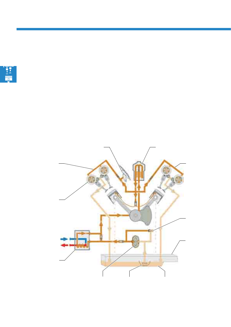
Cylinder bank 1
Chain tensioner
Oil filter module
Cylinder bank 2
Oil pressure
control valve
Oil pump
(gear)
Oil cooler
(coolant)
Hydraulic
camshaft
adjustment
Oil sump
upper section
Oil sump
lower section
Baffle plate
Oil supply
During development of the oil supply system, great emphasis was attached to the lowest possible oil throughput.
The camshaft adjusters and various friction bearings were therefore optimised. This engine's oil throughput, 50 l/
min at
7000 rpm and an oil temperature of 120°C, is very low.
The advantage is that the oil remains in the oil sump for a longer period of time, and that better water and
hydrocarbon (uncombusted fuel) degasification is possible. A smaller oil pump can additionally be used, as a result
of which the necessary drive power and therefore the fuel consumption are reduced.
A baffle plate in the area of the inlet connection ensures that no oil, which has been worked into a foam by the oil
pump, is drawn into to oil system.
The oil is cooled by an oil-water heat exchanger.
13
S388_019
Base filter suction side
Pressure oil side
Return from the engine
S388_020
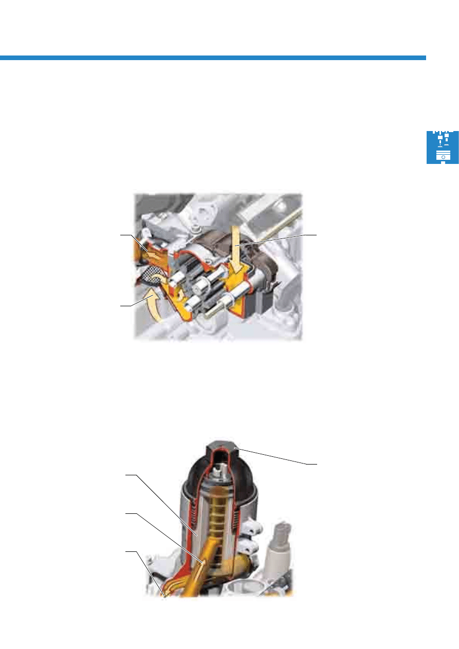
Cap
Filter element
consisting of
polymer mat
From the oil pump
pressure side
To the engine circuit
The oil pump is located inside the oil sump upper section, and is bolted to the ladder frame. Intake is carried out via
a filter on the base of the oil sump and, during vehicle operation, simultaneously via the engine's return duct. All
engine lubrication points are supplied from the pressure oil side.
The oil filter module is designed as a main flow filter. It is located in the innner V of the engine to facilitate
maintenance. The filter element can be easily exchanged without special tools. It consists of a polymer mat.
Oil pump
Oil filter module
14
Engine mechanics
Micro oil separator
Pressure limiting valve
Non-return valve
(crankcase breather system)
S388_023
Cooling circuit connection
for heating
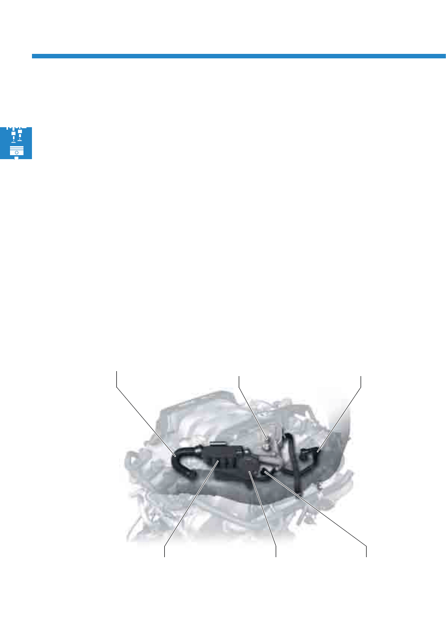
Crankcase breather
system
Vent line
Crankcase breather and ventilation system
Crankcase breather system
The crankcase breather system is used to flush fresh air through the crankcase. As a result of this, water vapour and
low-boiling hydrocarbons are flushed from the crankcase and the accumulation of water and uncombusted
hydrocarbons in the oil is avoided.
The air is removed downstream of the air filter, and is guided into the inner V of the cylinder block via a non-return
valve. A restrictor downstream of the non-return valve ensures that only the defined quantity of fresh air is supplied
to the crankcase.
Crankcase ventilation system
Via the crankcase ventilation system, the uncombusted hydrocarbons (blow-by gases) are returned to the
combustion process and do not escape into the outside air.
To minimise the oil contained in the blow-by gases, they are separated via a labyrinth oil separator in the cylinder
head cover and a three-stage cyclonic micro oil separator.
In the cylinder head cover, the gas encounters impact plates, on which the larger oil droplets are separated. The
gases are then channelled via hoses to the micro oil separator. Here, the smaller oil droplets are separated off,
thereby preventing inlet valve coking. The induction point downstream of the throttle valve module is integrated into
the cooling circuit to prevent it from freezing.
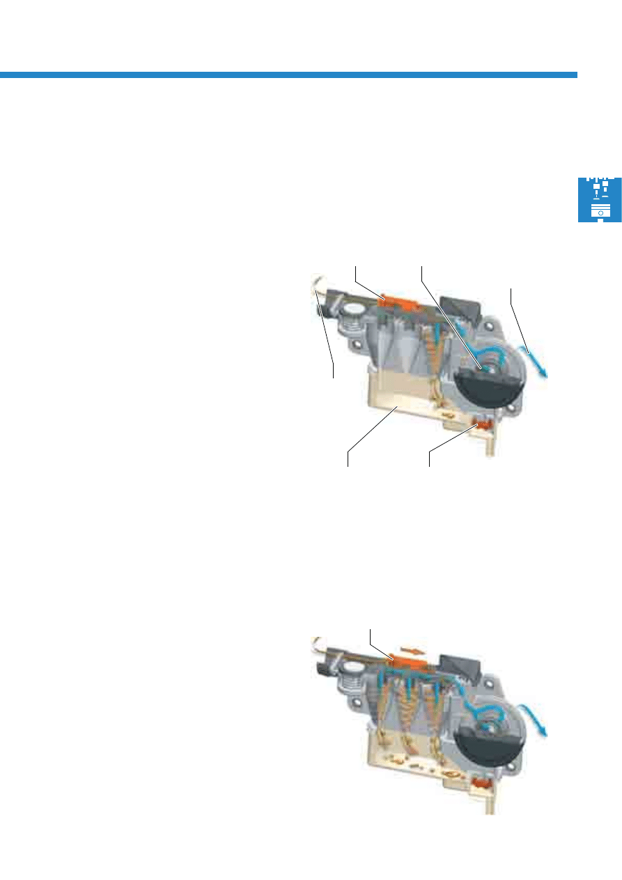
15
Low engine load/speed – low gas throughput
At low engine load and speed, the gas throughput is
low. The gas flows past the control plunger into the
first cyclonic oil separator. Here, the oil which is still
present in the gas is pressed outwards via centrifugal
force, adheres to the wall and drips into the oil
collection chamber.
The oil collection chamber contains an oil drain valve,
which is closed via the pressure in the crankcase when
the engine is running. If the engine is switched off, the
valve opens and the oil which is present flows into the
oil sump via a hose located below the level of the oil.
The pressure control valve ensures a constant pressure
level and good crankcase ventilation.
Increasing engine load/speed – increasing gas
throughput
As the engine load and speed increases, so to does
the mass flow of the blow-by gases. The higher the
mass flow, the greater the force which acts on the
control plunger. The control plunger force overcomes
the spring force and releases the access ducts to
further cyclones.
Three-stage cyclonic micro oil separator
The quantity of uncombusted hydrocarbons and oil vapour is dependent on the engine load and speed. The micro
oil is separated off via a three-stage cyclonic micro oil separator.
As cyclonic oil separators only perform well in a low volumetric flow range, one, two or three cyclones are released
in parallel depending on the throughput quantity of gas.
S388_024
Control plunger
Pressure control
valve
To the induction
point downstream of
the throttle valve
module
Oil drain valve
S388_026
Control plunger shifted
From the cylinder
head cover
Oil collection
chamber
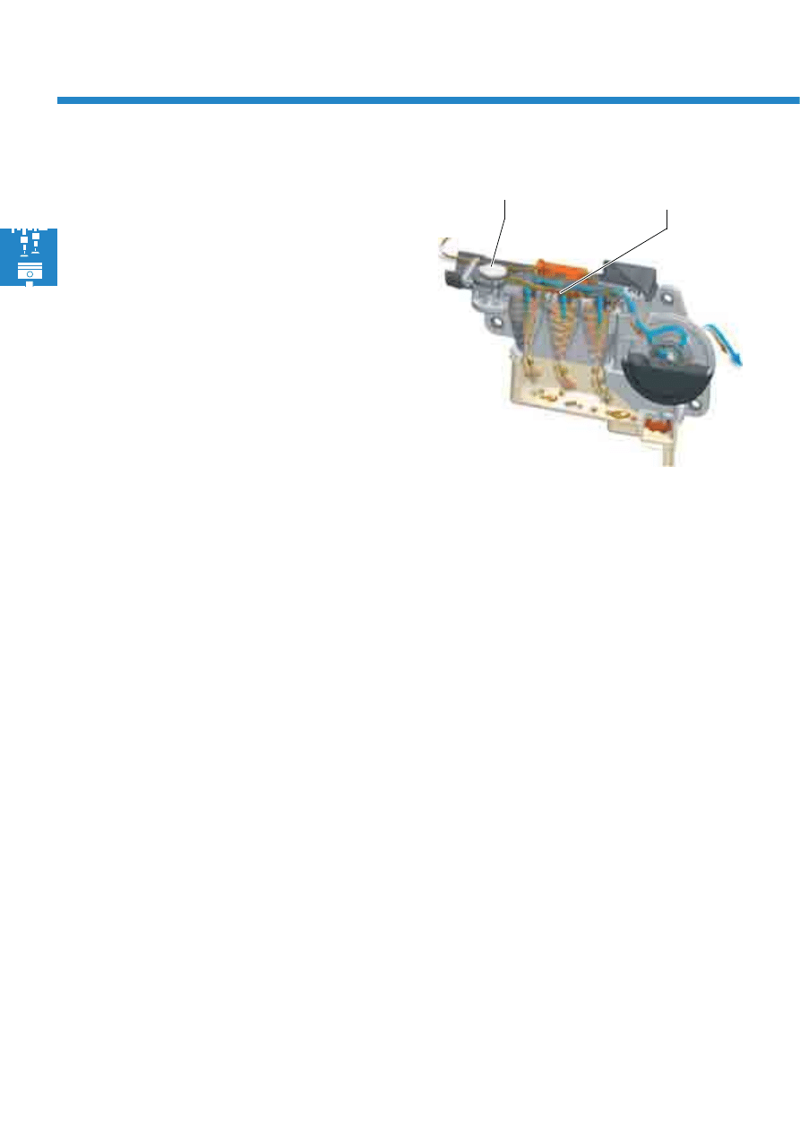
16
Engine mechanics
Bypass valve opens – very high gas throughput
The bypass valve ensures that the pressure in the
crankcase does not become excessive.
If the pressure in the crankcase increases rapidly, e.g.
due to a jammed control plunger or piston ring flutter
(may occur at high engine speeds and low load), the
cyclones are no longer able to cope with this pressure
increase. The pressure continues to rise and now
opens the bypass valve. Part of the blow-by gases
now flows past the cyclone and is guided to the intake
manifold directly via the pressure control valve.
S388_050
Bypass valve open
Gases flow past the
cyclones
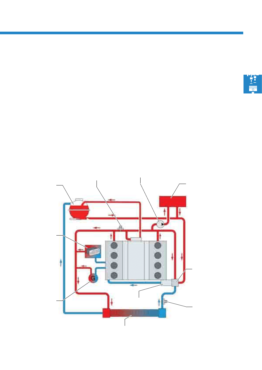
17
S388_016
Coolant temperature
sender G83
Radiator
Coolant distributor
housing with
map-controlled engine
cooling system
thermostat F265
Alternator
Coolant temperature
sender G62
Expansion
tank
Heating system
heat exchanger
Oil cooler
Coolant pump
Circulation pump V55
The cooling system is designed as a longitudinal cooling system. The coolant flows in on the intake side and, via the
cylinder head gasket, into the head, where it flows out longitudinally via the timing chain cover. Cylinder web
cooling has been improved by drilling coolant ducts with optimised cross-sections into the webs. Forced flow
through these bores is ensured with the aid of specifically sealed water ducts.
In addition, the engine is equipped with an electronically controlled cooling system.
- In the partial load range which is not critical with regards to knocking, the coolant temperature is regulated to
105°C. In the lower partial load range, the thermodynamic advantages and reduced friction power result in a
fuel saving of approx. 1.5%.
- In the full load range, the coolant temperature is regulated to 90°C via the map-controlled engine cooling
system thermostat. Cooler combustion chambers and better cylinder charging with reduced knocking tendency
are achieved as a result.
Cooling circuit
18
Engine mechanics
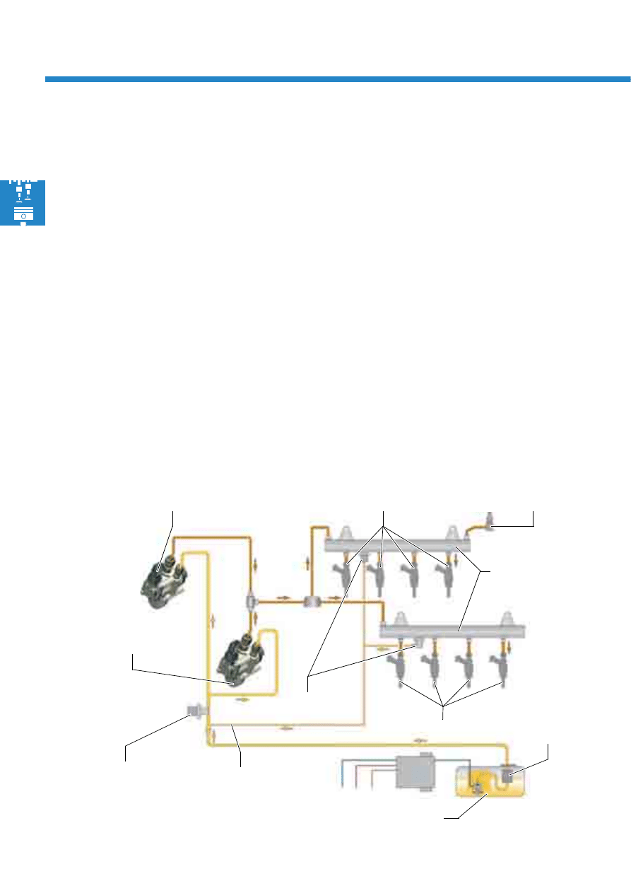
S388_027
Fuel rail
High-pressure fuel pump
with fuel metering valve 2
N402
Fuel pressure sender
for low pressure G410
Leakage line
Fuel filter
integrated into
tank
Injectors, cylinders 5-8
N83-N86
Pressure limiting
valve (120 bar)
Fuel tank
Fuel pressure sender,
high pressure G247
Injectors, cylinders 1-4 N30-N33
High-pressure fuel pump with fuel
metering valve N290
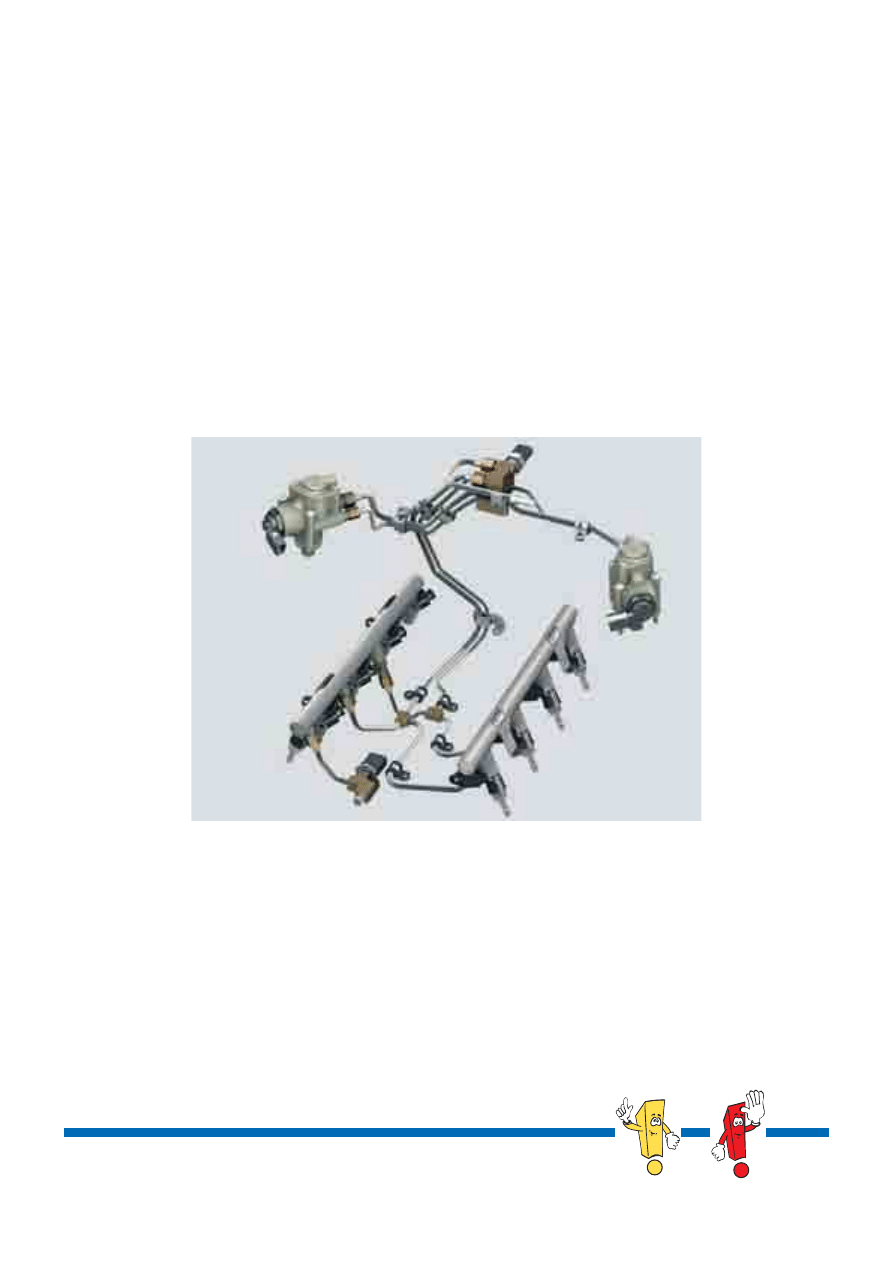
Fuel system
The fuel system is a requirement-controlled fuel system. This means that both the electronic fuel pump and the two
high-pressure fuel pumps only deliver the amount of fuel required by the engine at that particular moment. As a
result of this, electrical and mechanical power requirements are reduced and fuel consumption is lowered.
The fuel system is sub-divided into a low-pressure and a high-pressure fuel system.
- The fuel pressure of up to 7 bar in the low-pressure fuel system is generated by an electronic fuel pump, which is
actuated by the engine control unit via a fuel pump control unit.
- The fuel pressure of 25 to 105 bar in the high-pressure fuel system is generated by two mechanical high-pressure
fuel pumps, each of which is driven via a dual cam by the inlet camshafts.
To minimise fuel pressure pulsations, both high-pressure fuel pumps deliver fuel into a common fuel line to the
fuel rails. In addition, this high-pressure delivery has been chosen in such a way that both pumps' delivery into
the high-pressure area is offset.
19
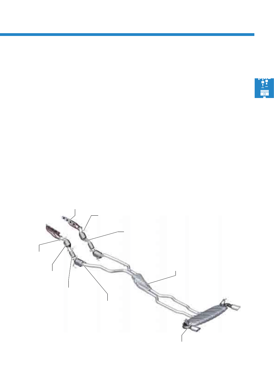
Exhaust system
The exhaust system is a twin-branch design. This means that each cylinder block has a separate exhaust tract.
The exhaust manifolds are insulated sheet metal manifolds with a gas-tight inner shell. This air-gap insulation
enables a compact design and fast heating. Additional heat shield measures are no longer necessary. The exhaust
manifolds are secured to the cylinder heads using clamping flange technology.
Two broadband lambda probes are installed downstream of the exhaust manifolds and two transient lambda
probes downstream of the starter catalytic converters.
The starter and main catalytic converters' substrate material is comprised of ceramic.
Both exhaust tracts end in the front silencer. There, the sound waves overlap and noise emissions decrease. Two
exhaust pipes lead from the front silencer to the rear silencer. Both exhaust pipes are routed separately in the
interior of the rear silencer.
The front and rear silencers function as absorption silencers.
The exhaust gas flows into the outside air via two tailpipes.
Front silencer
Broadband
lambda probe
G108
S388_028
Exhaust manifold with
air-gap insulation
Rear silencer
Main catalytic
converters
Starter catalytic
converters
Transient
lambda probe G131
Transient
lambda probe G130
Broadband
lambda probe
G39
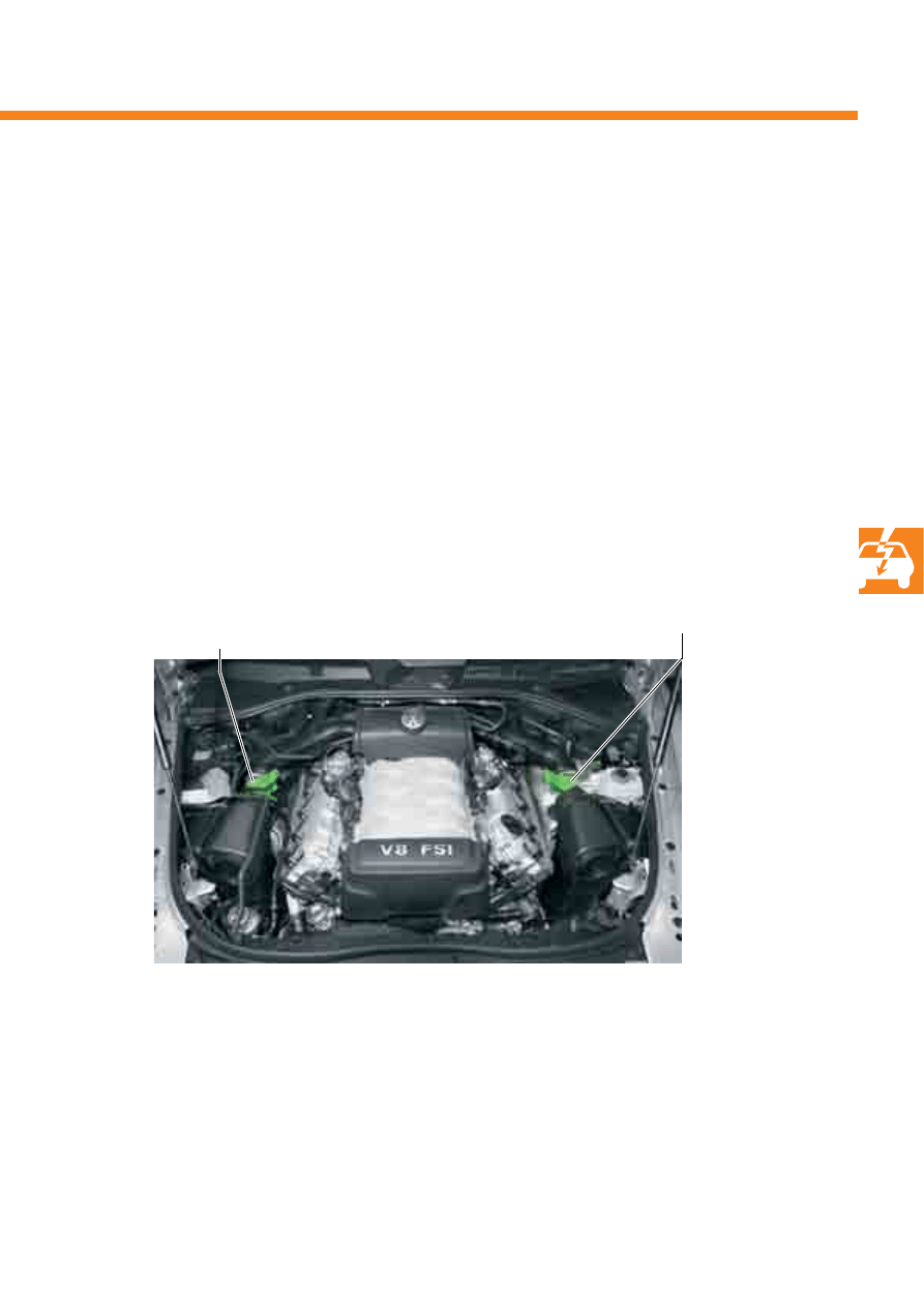
20
Engine mechanics
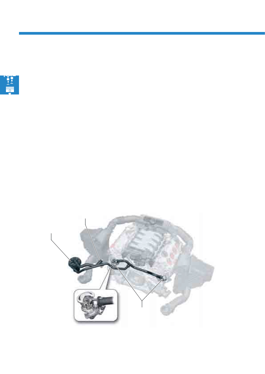
Secondary air system
Secondary air pump
Connection on the air filter
Combination valves
(self-opening)
S388_029
To heat the catalytic converters as quickly as possible, the mixture is enriched with fuel on cold-starting and during
warming up. This results in a higher percentage of uncombusted hydrocarbons in the exhaust gas during this
period.
Thanks to air injection downstream of the exhaust valves, the exhaust gases are enriched with oxygen, leading to
oxidation (afterburning) of the hydrocarbons and the carbon monoxide. The heat released during this process also
heats the catalytic converter, helping it to reach its operating temperature faster.
The secondary air system is comprised of:
- the secondary air pump relay J299,
- the secondary air pump motor V101 and
- two self-opening combination valves
Input signals
- Signal from the lambda probes (for system diagnosis)
- Coolant temperature
- Air mass meter engine load signals
21
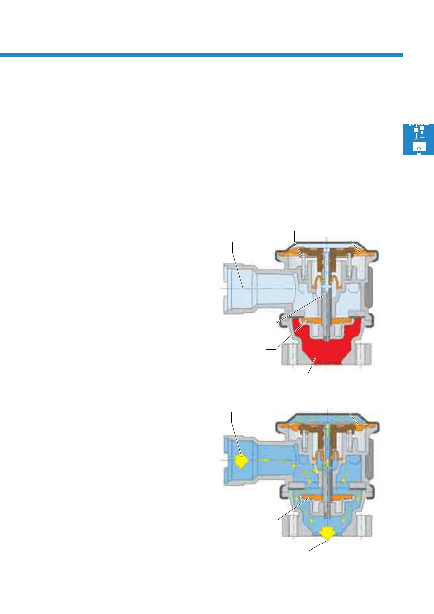
S388_015
Exhaust gas side
Diaphragm
Spring
Secondary air injection
The secondary air system is switched on during cold-starting, at the start of the warm-up phase and for test
purposes as part of EOBD. In this case, the engine control unit actuates the secondary air pump via the secondary
air pump relay. When the pressure which has been generated is present at the combination valves, they open and
the air flows downstream of the exhaust valves. Afterburning takes place.
S388_057
To the exhaust valves
Diaphragm
Function of the combination valves
The combination valves are self-opening valves. This means that they are opened via the pressure generated by the
secondary air pump, and not via vacuum as in the previous secondary air systems.
Combination valve closed
The pressure in the combination valves corresponds to
ambient pressure. The valves are closed.
Combination valve open
If the current for the secondary air pump is activated
via the relay, it begins to deliver air. Pressure builds up
due to the fact that the combination valve is closed.
This is present at the valve disk and, via the
hollowed-out valve stem, at the diaphragm. If a
pressure of approx. 450 mbar above ambient
pressure acts on the diaphragm and the valve disk,
the valve opens.
The air delivered by the secondary air pump now
flows downstream of the exhaust valves and
afterburning takes place.
Valve stem
hollowed out
Valve disk closed
Valve disk open
From the
secondary air pump
From the
secondary air pump
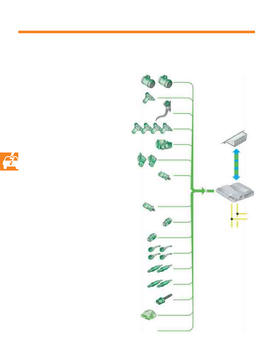
22
Engine management
Air mass meter G70, G246
Intake air temperature sender G42
System overview
Coolant temperature sender G62
Radiator outlet coolant temperature sender G83
Intake manifold flap potentiometer G336, G512
Lambda probe G39, G108
Brake servo pressure sensor G294
Additional input signals
Hall sender G40, G163, G300, G301
Fuel pressure sender for high pressure G247
Brake light switch F
Brake pedal switch F47
Fuel pressure sender for low pressure G410
Accelerator position sender G79 and G185
Engine speed sender G28
Engine control
unit J623
CAN drive data
bus
Lambda probe after catalytic converter G130, G131
Sensors
Throttle valve module J338
Angle sender for throttle valve drive G187, G188
Knock sensors G61, G66, G198, G199
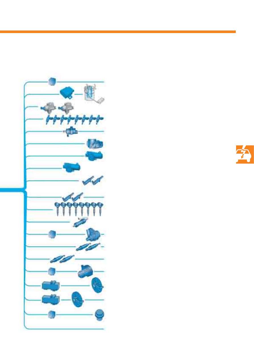
23
Fuel pump control unit J538
Fuel pump G6
Continued coolant circulation relay J151
Circulation pump V55
Inlet camshaft control valves N205, N208
Fuel metering valve N290, N402
Throttle valve module J338
Throttle valve drive for electric throttle G186
Ignition coil 1 - 8 with output stage
N70, N127, N291, N292, N323-N326
Injectors for cylinders 1 - 8 N30-33, N83-N86
Lambda probe heater Z19, Z28
S388_030
Additional output signals
Actuators
Active charcoal filter system solenoid valve N80
Map-controlled engine cooling system
thermostat F265
Secondary air pump relay J299
Secondary air pump motor V101
Intake manifold flap motor V157
Radiator fan control unit J293
Radiator fan V7
Motronic current supply relay J271
Variable intake manifold motor V183
Exhaust camshaft control valves N318, N319
Lambda probe heater after
catalytic converter Z29, Z30
Brake servo relay J569
Vacuum pump for brakes V192
Radiator fan control unit 2 J671
Radiator fan V177
24
J428
J197
J519
T16
J217
J533
J518
CAN drive data bus
CAN convenience
data bus
G85
S388_031
J234
J255
J623
J644
J646
J104
J527
J285
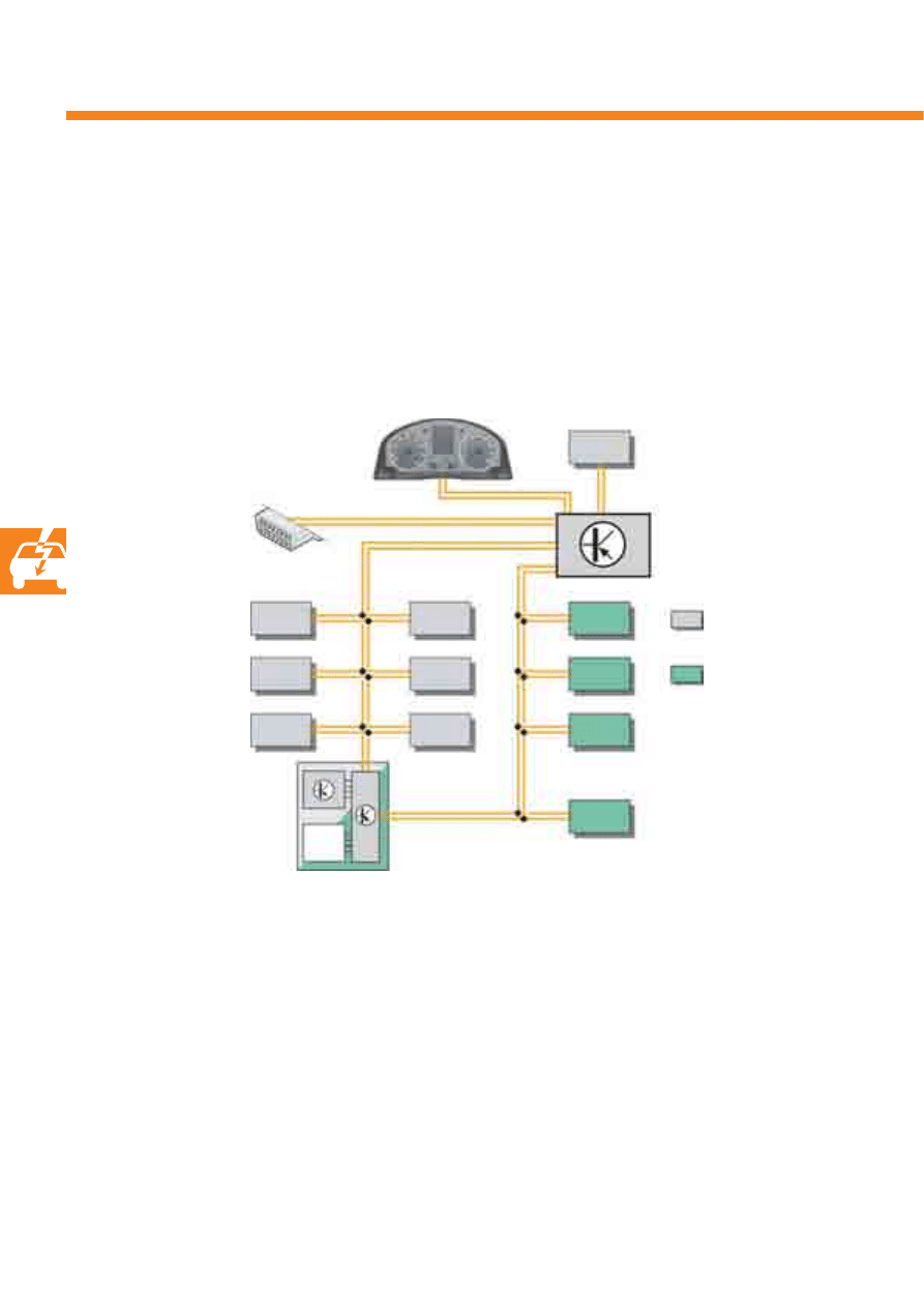
Engine management
The diagram below shows the control units with which the engine control unit J623 communicates via the
CAN data bus and exchanges data.
CAN networking
G85
Steering angle sender
J104
ABS control unit
J197
Adaptive suspension control unit
J217
Automatic gearbox control unit
J234
Airbag control unit
J255
Climatronic control unit
J285
Control unit with display in dash panel insert
J428
Adaptive cruise control unit
J518
Entry and start authorisation
control unit
J519
Onboard supply control unit
J527
Steering column electronics control unit
J533
Data bus diagnostic interface
J623
Engine control unit
J644
Energy management control unit
J646
Transfer box control unit
T16
Diagnosis connector
25
S388_032
To minimise pressure losses, the intake tract has a
twin-branch design. The most accurate possible air
mass signal is achieved by two hot film air mass
meters. Hot film air mass meter G70 is installed along
with intake air temperature sender G42 in the intake
tract on the cylinder bank 1 side. Hot film air mass
meter G246 is installed in the intake tract on the
cylinder bank 2 side.
From the signals transmitted by the two air mass
meters and the intake air temperature sender, the
engine control unit calculates the mass and the
temperature of the intaken air respectively.
Signal use
The signals are used to calculate all load- and engine
speed-dependent functions. These include the
injection period, ignition timing or camshaft
adjustment, for example.
Sensors
Effects in the event of failure
If one or both air mass meters fail, the throttle valve
position and the engine speed are used as correction
values.
If the intake air temperature sender fails, a fixed,
substitute value is assumed.
Hot film air mass meter G246
cylinder bank 2
Hot film air mass meter G70 with intake air temperature sender G42 and hot
film air mass meter 2 G246
Hot film air mass meter G70 with
intake air temperature sender G42
cylinder bank 1
26
Engine management
S388_034
Signal use
The signals are used to detect the first cylinder, for
camshaft adjustment, and to calculate the injection
point and the ignition timing.
Effects in the event of signal failure
No further camshaft adjustment takes place if a Hall
sender fails. The engine continues to run and also
re-starts again after switching off thanks to run-on
recognition. Torque and power are reduced at the
same time.
Hall sender G40, G163, G300, G301
Hall sender G163
Cylinder bank 1
Hall sender G40 - inlet camshaft
Hall sender G300 - exhaust camshaft
Cylinder bank 2
Hall sender G163 - inlet camshaft
Hall sender G301 - exhaust camshaft
S388_033
Hall sender G40
Hall senders G40 and G300 are located on cylinder
bank 1 and Hall senders G163 and G301 are located
on cylinder bank 2.
By scanning a quick-start sender wheel, the engine
control unit recognises the position of each cylinder
bank's inlet and exhaust camshafts.
Hall sender G300
Hall sender G301
27
Fuel pressure sender for low pressure G410
The sender is installed in the supply line to the two
high-pressure fuel pumps. It measures the fuel
pressure in the low-pressure fuel system and transmits
a signal to the engine control unit.
Signal use
The signal is used by the engine control unit to
regulate the low-pressure fuel system.
Following the sender signal, the engine control unit
transmits a signal to the fuel pump control unit J538,
which then regulates the electronic fuel pump G6 as
required.
Effects in the event of signal failure
If the fuel pressure sender fails, the fuel pressure is
regulated by a fuel pressure pilot control system. The
fuel pressure is then approx. 6.5 bar.
S388_035
Fuel pressure sender
for low pressure G410
28
Engine management
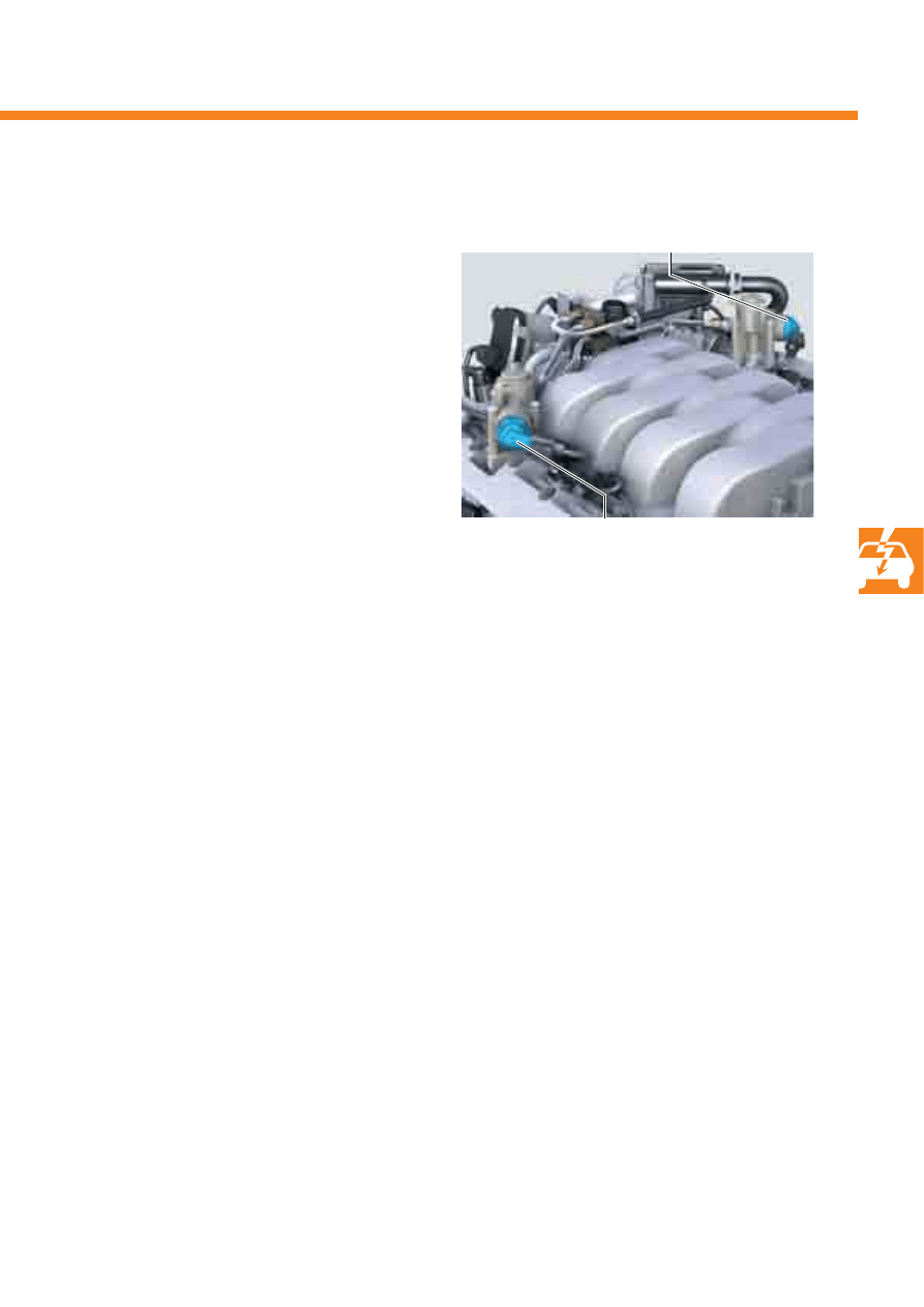
Fuel pressure sender, high pressure G247
The sender is located in the inner V of the cylinder
block, and is connected to the fuel rail via a line.
It measures the fuel pressure in the high-pressure fuel
system and transmits the signal to the engine control
unit.
S388_036
Signal use
The engine control unit evaluates the signals and
regulates the pressure in the fuel rail pipes via the two
fuel metering valves.
Effects in the event of signal failure
If the fuel pressure sender fails, no further high fuel
pressure is built up. The engine runs in emergency
mode with low fuel pressure. Power and torque are
reduced.
Fuel pressure sender,
high pressure G247
Fuel rail
29
S388_037
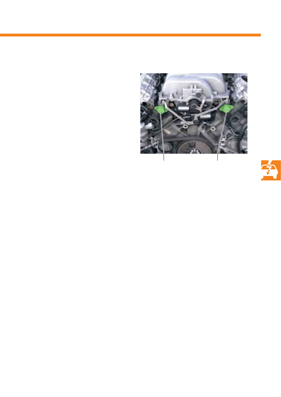
Intake manifold flap potentiometer G336 and G512
The two intake manifold flap potentiometers are
secured to the intake manifold and are connected to
the shaft for the intake manifold flaps. They recognise
the position of the intake manifold flaps.
Signal use
The position is important, as intake manifold
change-over affects air flow in the combustion
chamber and the inlet air mass. The position of the
intake manifold flaps is therefore relevant to the
exhaust gas, and must be checked via self-diagnosis.
Effects in the event of signal failure
If the signal from the potentiometer fails, the position
of the intake manifold flaps at the time of failure and
the relevant ignition timing are used as substitute
values. Power and torque are reduced and fuel
consumption increases.
Potentiometer for
intake manifold flap G512
Potentiometer for
intake manifold flap G336
30
Engine management
Fuel pump G6
The electronic fuel pump and the fuel filter are
combined to form a fuel delivery unit.
The fuel delivery unit is located in the fuel tank.
Task
The electronic fuel pump delivers the fuel in the low-
pressure fuel system to the high-pressure fuel pump. It
is actuated with a PWM signal by the fuel pump
control unit.
The electronic fuel pump always supplies the quantity
of fuel required by the engine at the present moment
in time.
The fuel pump control unit is mounted under the rear
seat bench in the cover for the electronic fuel pump.
Task
The fuel pump control unit receives a signal from the
engine control unit and controls the electronic fuel
pump with a PWM signal (pulse-width modulation). It
regulates the pressure in the low-pressure fuel system
between 5 and 7 bar.
Effects in the event of signal failure
If the fuel pump control unit fails, engine operation is
not possible.
Fuel pump control unit J538
Actuators
S388_038
Effects in the event of failure
If the electronic fuel pump fails, engine operation is
no longer possible.
S388_039
Fuel pump G6
Fuel pump control unit J538
31
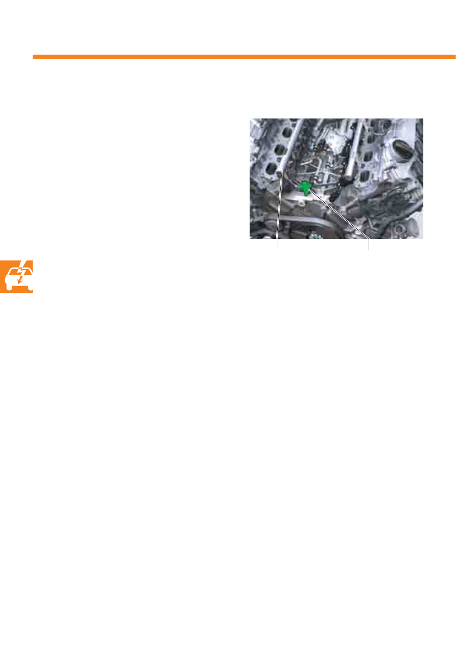
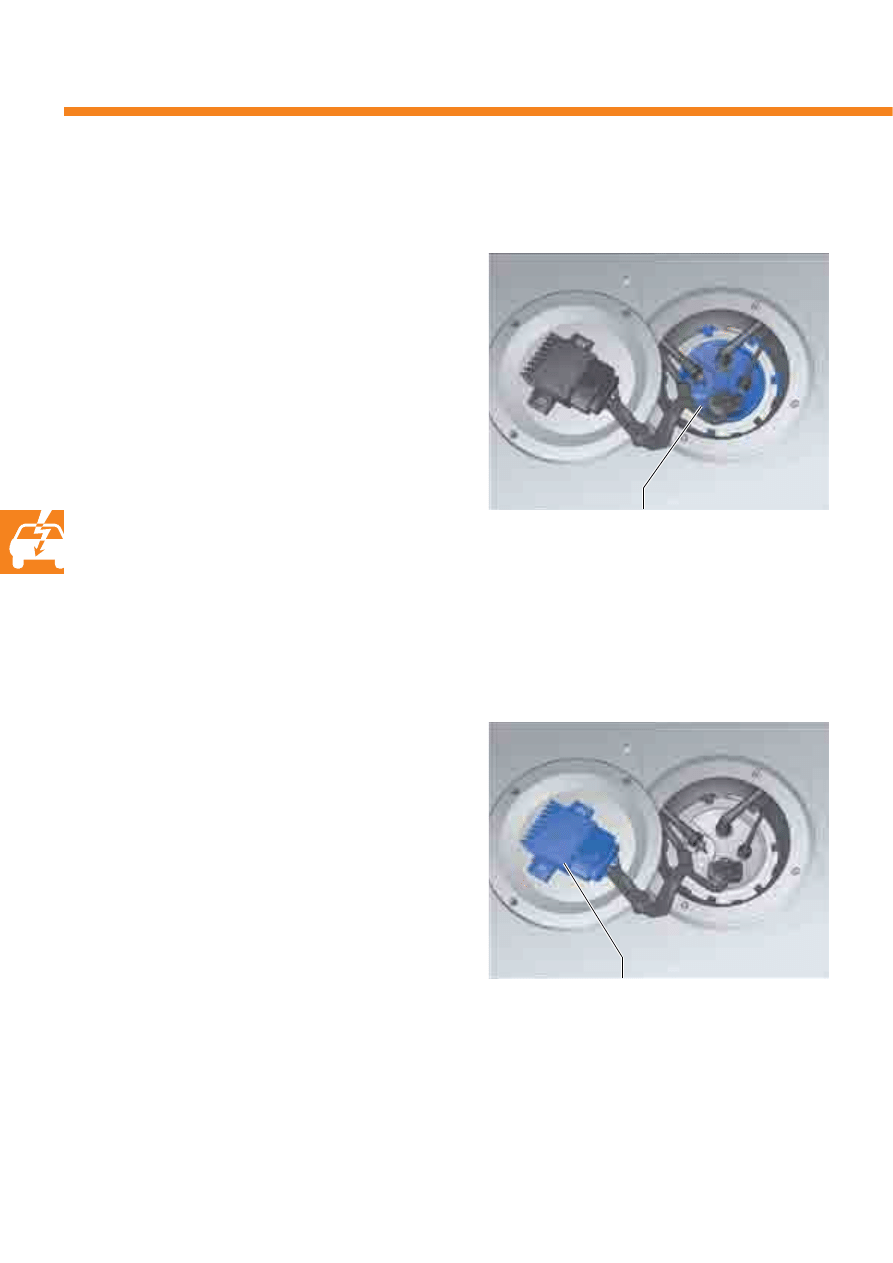
Fuel metering valve N290 and N402
The fuel metering valves are located at the sides of
the high-pressure fuel pumps.
S388_040
Fuel metering valve N290
Fuel metering valve N402
Task
They have the task of making the required quantity of
fuel available at the required fuel pressure in the fuel
rail pipe.
Effects in the event of signal failure
The regulating valve is open when currentless. This
means that high pressure is not built-up and the
engine is run with the existing fuel pressure from the
electronic fuel pump. As a result of this, output and
torque are significantly reduced.
32
Engine management
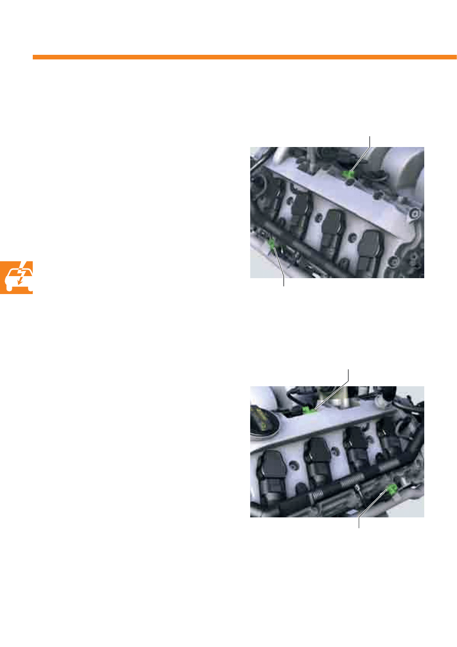
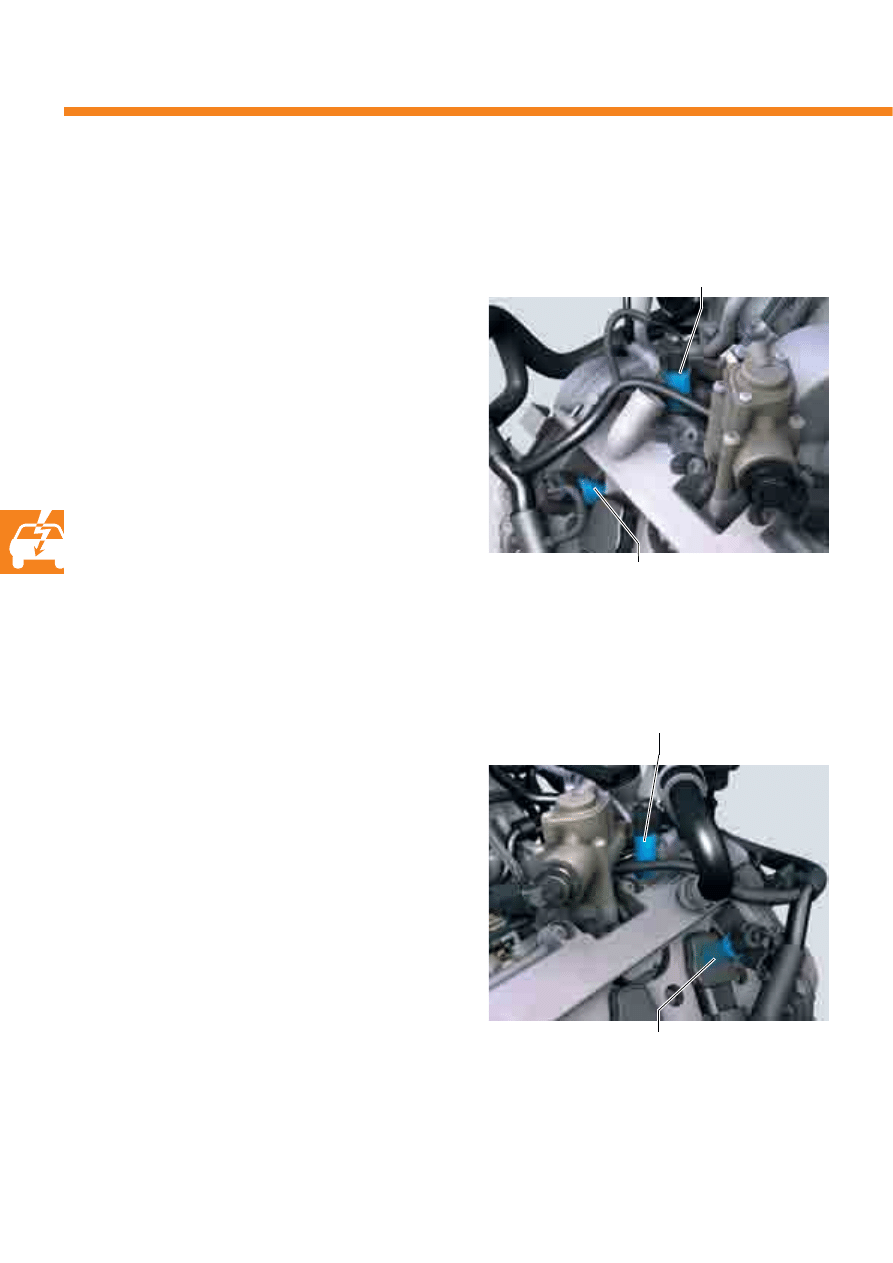
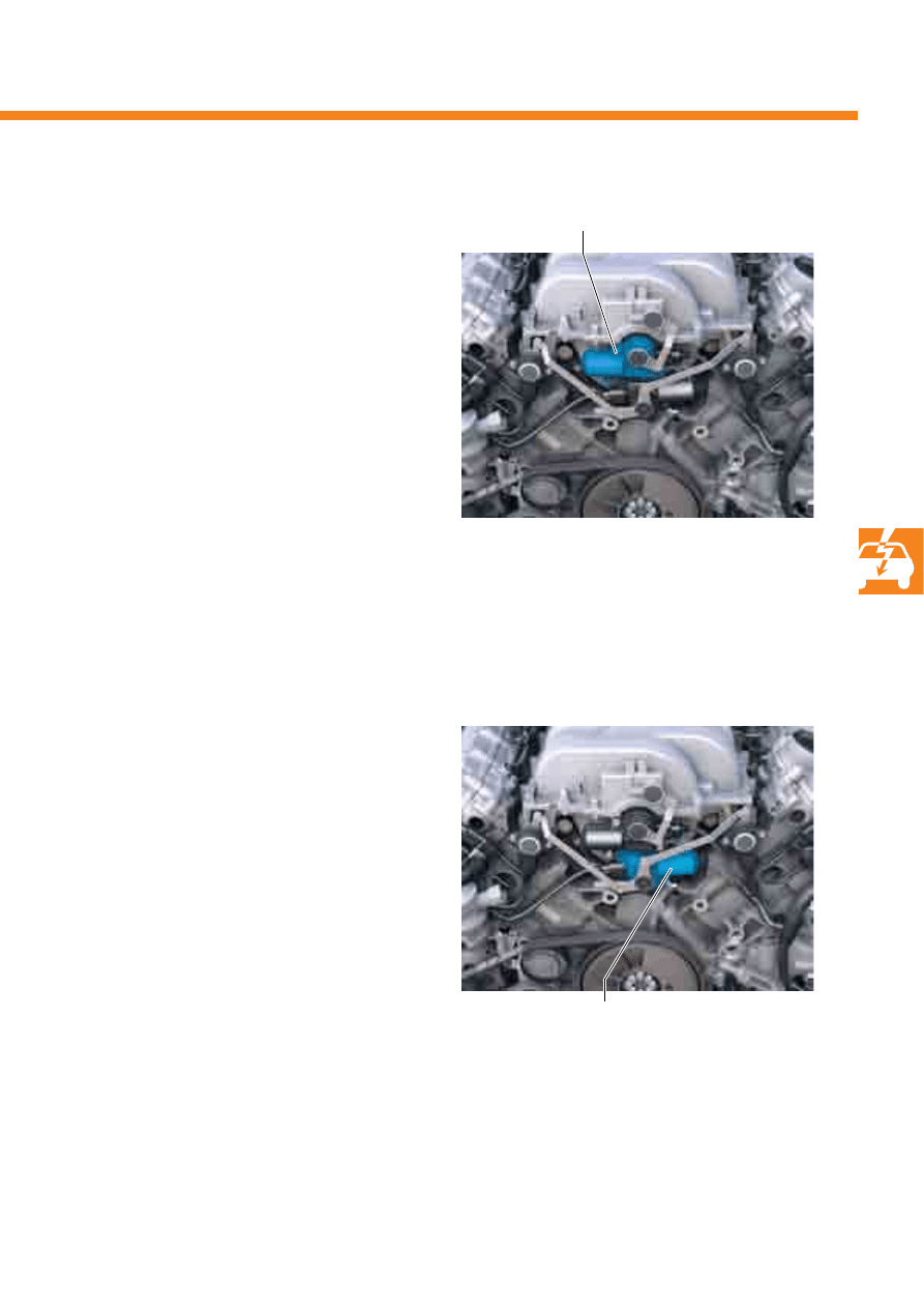
Inlet camshaft control valve 1 and 2 N205 and N208
Exhaust camshaft control valve 1 and 2 N318 and N319
These solenoid valves are secured to the cylinder
head covers.
Task
Depending on actuation by the engine control unit,
they distribute the oil pressure to the camshaft
adjusters according to the adjustment direction and
adjustment travel.
Both camshafts are infinitely adjustable:
- Inlet camshaft 42° crank angle
- Exhaust camshaft 42° crank angle
- Maximum valve overlap angle 47° crank angle
When no oil pressure is available (engine switched
off), the exhaust camshaft is mechanically locked.
Effects in the event of signal failure
If an electrical cable to the camshaft adjusters is
defective or a camshaft adjuster fails due to
mechanical jamming or insufficient oil pressure,
no further camshaft adjustment is carried out. Power
and torque are reduced.
S388_041
S388_042
Inlet camshaft
control valve 2 N208
Inlet camshaft
control valve 1 N205
Exhaust camshaft
control valve 1 N318
Exhaust camshaft
control valve 2 N319
33
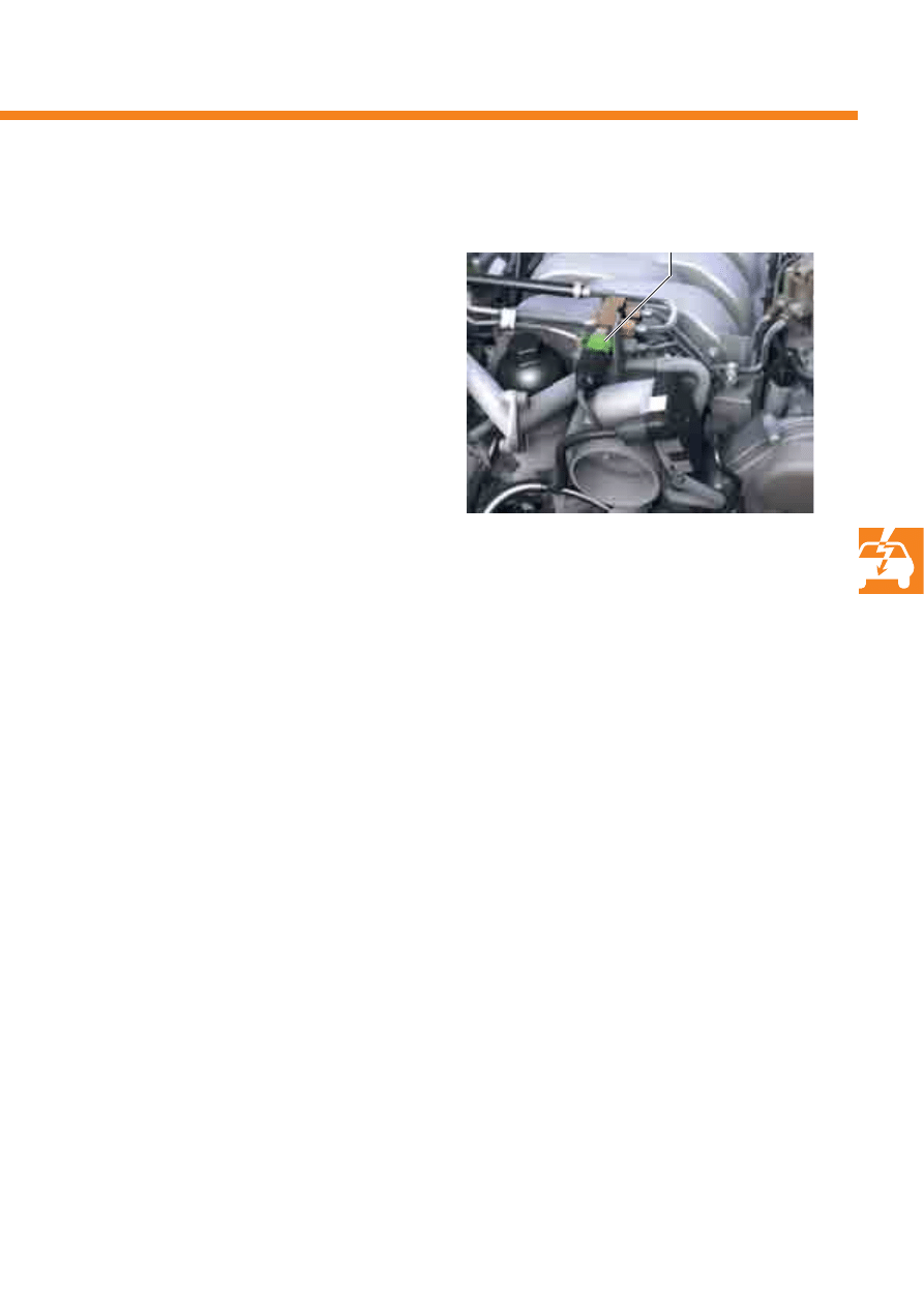
Variable intake manifold motor V183
The variable intake manifold motor is bolted to the
intake manifold.
Effects in the event of failure
If the variable intake manifold motor fails, intake
manifold change-over is no longer possible. The
intake manifold remains in the position in which the
change-over flaps were located at the time of failure.
Power and torque are reduced.
Task
The motor is actuated by the engine control unit
depending on engine load and speed.
The motor actuates the change-over flaps via a shaft
and switches to the torque or the output position.
Intake manifold flap motor V157
The intake manifold flap motor is bolted to the
variable intake manifold.
Task
The motor is actuated by the engine control unit
depending on engine load and speed. Via two
operating rods, it thereby adjusts four intake manifold
flaps per cylinder bank.
If these are actuated, they close part of the intake port
in the cylinder head. This leads to cylindrical air
movement in the cylinder head and improves mixture
formation.
Effects in the event of failure
If the intake manifold motor fails, the intake manifold
flaps can no longer be actuated. This leads to a
deterioration in combustion and a reduction in output
and torque. The fuel consumption also increases.
Intake manifold flap motor V157
S388_043
Variable intake manifold motor V183
S388_044
34
31
30
15
87a
P
Q
J
623
G6
J538
G
J285
J285
J285
G169
A
N30
N7
0
P
Q
N12
7
P
Q
N291
P
Q
N292
P
Q
N323
P
Q
N324
P
Q
P
G79
G185
Q
N325
N326
N8
4
N31
N86
N32
N83
N33
N8
5
S
S
S
S
J271
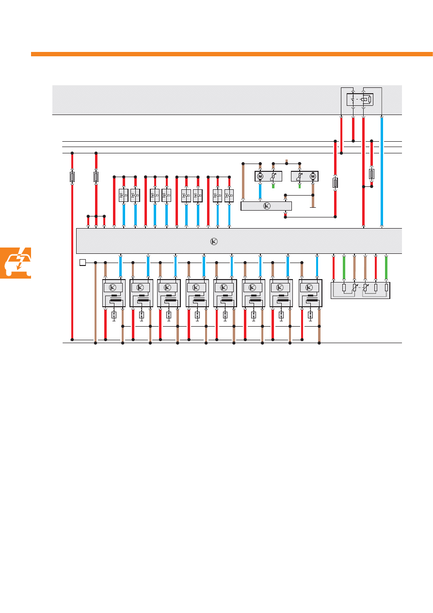
Functional diagram
A
Battery
G
Fuel gauge sender
G6
Fuel pump
G79
Accelerator position sender
G169
Fuel gauge sender 2
G185
Accelerator position sender 2
J271
Motronic current supply relay
J285
Control unit with display in dash panel insert
J538
Fuel pump control unit
J623
Engine control unit
N30-
Injector, cylinder 1 to
N33
Injector, cylinder 4
N70
Ignition coil 1 with output stage
N83-
Injector, cylinder 5 to
N86
Injector, cylinder 8
N127
Ignition coil 2 with output stage
N291- Ignition coil 3 with output stage
N292 Ignition coil 4 with output stage
N323- Ignition coil 5 with output stage to
N326 Ignition coil 8 with output stage
P
Spark plug connector
Q
Spark plugs
S
Fuse
35
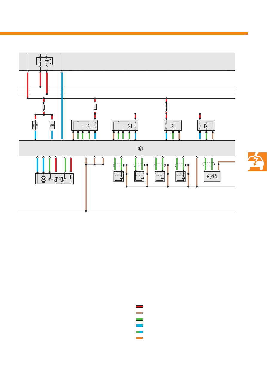
G28
Engine speed sender
G39
Lambda probe
G61
Knock sensor 1
G66
Knock sensor 2
G108 Lambda probe 2
G130
Lambda probe after catalytic converter
G131
Lambda probe 2 after catalytic converter
G163
Hall sender 2
G186
Throttle valve drive
G187
Throttle valve drive angle sender
G188
Throttle valve drive angle sender
G198
Knock sensor 3
G199
Knock sensor 4
J338
Throttle valve module
J623
Engine control unit
J757
Engine component current supply relay
N290 Fuel metering valve
N402 Fuel metering valve 2
S
Fuse
Z19
Lambda probe heater
Z28
Lambda probe 2 heater
Z29
Lambda probe 1 heater after
catalytic converter
Z30
Lambda probe 2 heater after
catalytic converter
Positive
Earth
Input signal
Output signal
Bi-directional cable
CAN data bus
N290
N402
G39/Z19
G108/Z28
G130/Z29
G131/Z30
J623
G186
G187
G188
G61
G66
G198
G199
G28
G163
J338
S
S
S
J757
S388_045
36
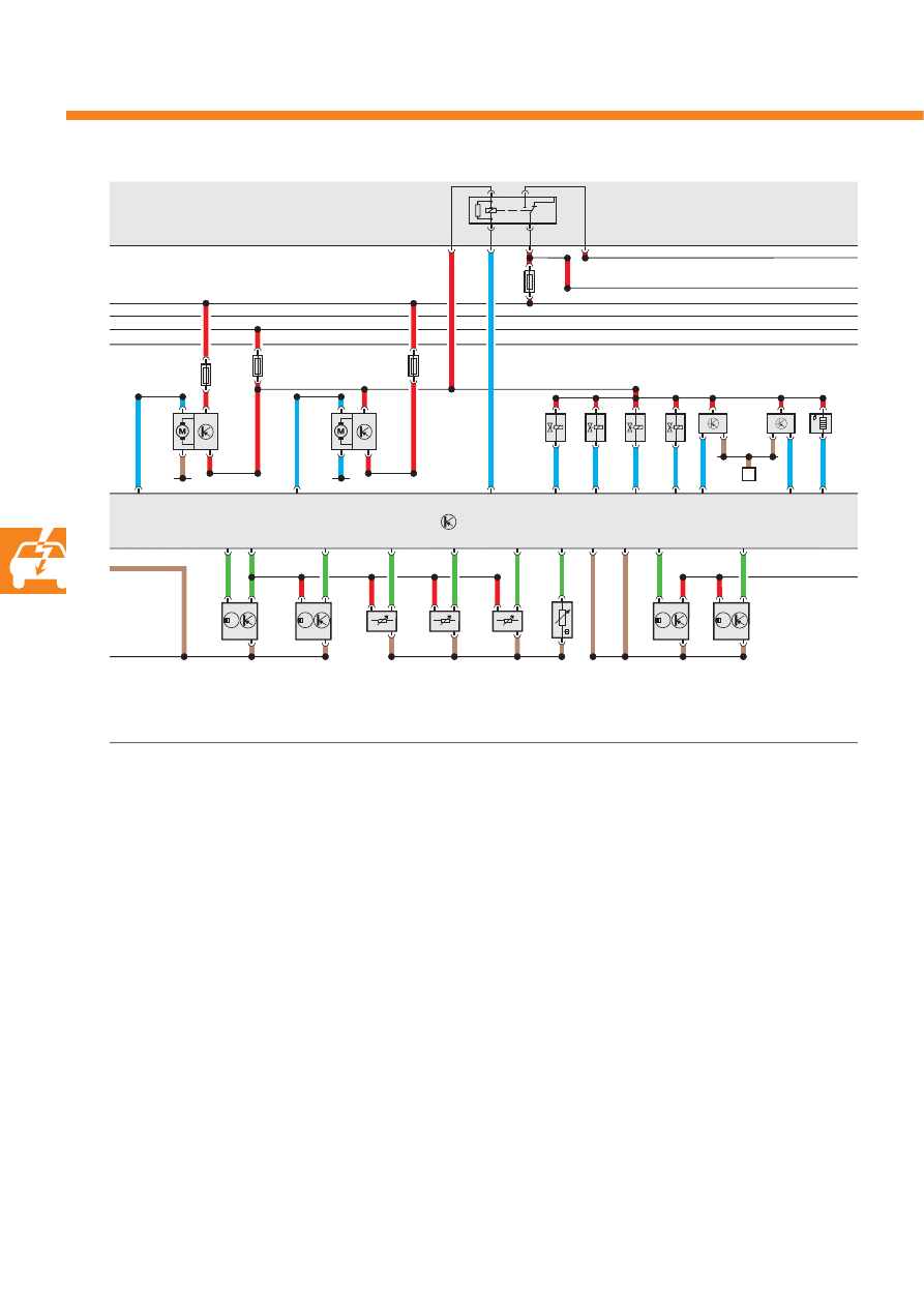
Functional diagram
V7
J293
V177
J671
J623
G163
G40
G336
G512
G247
G62
G300
G301
N205
N208
N318
N31
9
V183
F26
5
V15
7
S
S
S
S
J151
A
S388_045
A
Battery
F265
Map-controlled engine cooling system
thermostat
G40
Hall sender
G62
Coolant temperature sender
G163
Hall sender 2
G247 Fuel pressure sender, high pressure
G300 Hall sender 3
G301
Hall sender 4
G336 Intake manifold flap potentiometer
G512
Intake manifold flap potentiometer 2
J151
Continued coolant circulation relay
J293
Radiator fan control unit
J623
Engine control unit
J671
Radiator fan control unit 2
N205 Inlet camshaft control valve 1
N208 Inlet camshaft control valve 2
N318
Exhaust camshaft control valve 1
N319
Exhaust camshaft control valve 2
S
Fuse
V7
Radiator fan
V157
Intake manifold flap motor
V177
Radiator fan 2
V183
Variable intake manifold motor
37
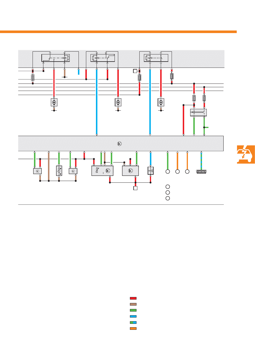
J623
G410
G294
G70
G42
G246
N80
K
m
G83
V55
V192
V101
J299
J569
J708
F47
F
J508
J255
S
S
S
S
S
B
B
1
1
2
3
2
3
Reversing light switch
CAN data bus
CAN data bus
S388_045
B
Starter
F
Brake light switch
F47
Brake pedal switch
G42
Intake air temperature sender
G70
Air mass meter
G83
Radiator outlet coolant
temperature sender
G246 Air mass meter 2
G294 Brake servo pressure sensor
G410
Fuel pressure sender for low pressure
K
Dash panel insert
J255
Climatronic control unit
J299
Secondary air pump relay
J508
Brake light suppression relay
J569
Brake servo relay
J623
Engine control unit
J708
Residual heat relay
N80
Active charcoal filter system solenoid valve 1
S
Fuse
V55
Circulation pump
V101
Secondary air pump motor
V192
Vacuum pump for brakes
Positive
Earth
Input signal
Output signal
Bi-directional cable
CAN data bus
38
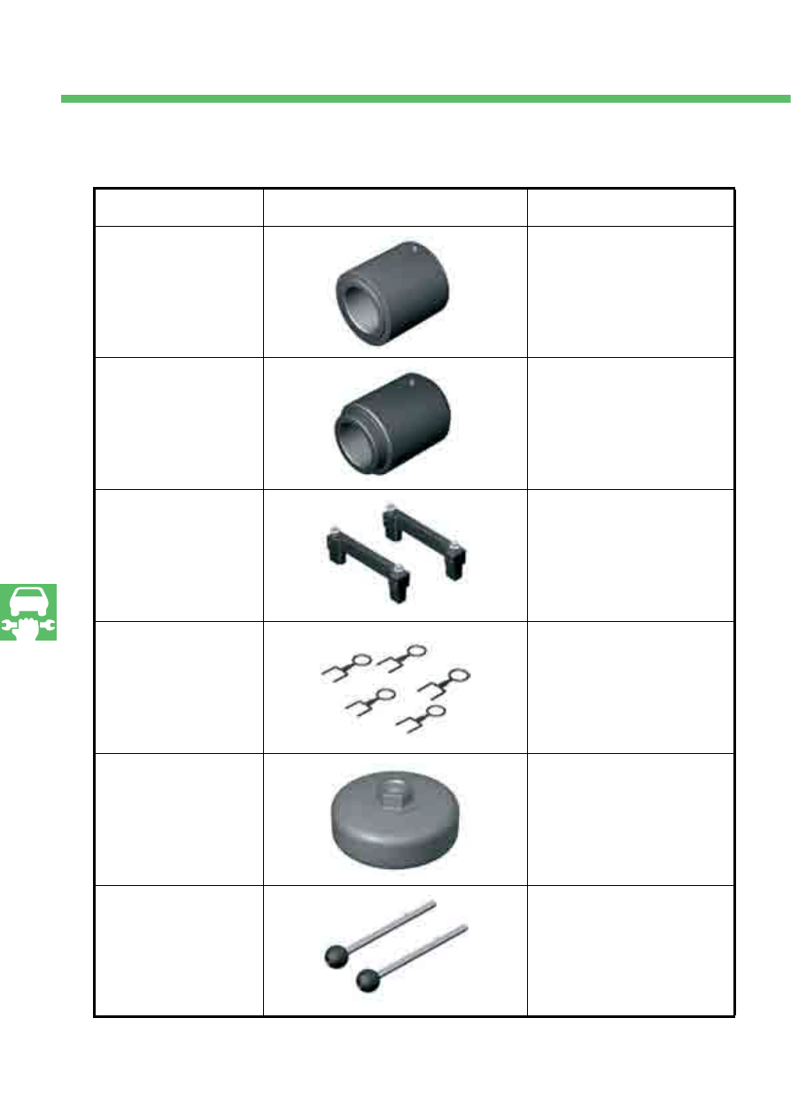
Service
Special tools
Designation
Tool
Application
Thrust piece
T 40051
For installing A/C compressor
drive sealing ring.
Thrust piece
T40052
For installing power steering
pump drive sealing ring.
Camshaft clamps
T40070
For locking camshafts on cylinder
bank 1 and cylinder bank 2.
Locking pins
T40071
For locking chain tensioners for
chain drives A, B, C, D.
Key
T40079
For pre-tensioning inlet and
exhaust camshafts after installing
the camshaft timing chain.
Locating pins
T40116
For locating the ladder frame on
attachment to the cylinder head.

39
Test yourself
1. How are the camshafts driven?
a) Via a toothed belt drive.
b) Via an individual roller chain from the crankshaft.
c) From the crankshaft, a roller chain drives two drive chain sprockets for the camshaft timing chains. In turn,
these drive the camshafts via one chain each.
2. How is intake manifold change-over carried out?
a) Intake manifold change-over is carried out via a vacuum unit.
b) Intake manifold change-over is carried out via a variable intake manifold electric motor.
c) Intake manifold change-over is carried out via a Bowden cable.
3. Which statement on the high-pressure fuel pumps is correct?
a) Each of the two high-pressure fuel pumps delivers to one cylinder bank.
b) Both high-pressure fuel pumps deliver the fuel jointly to both fuel rails.
c) One or both high-pressure fuel pumps deliver fuel depending on engine load and speed.
Answ
ers
1. c
2. b
3. b
4. a
Which answer is correct?
4. Which statement on the cooling system is correct?
a) It is an electronically controlled cooling system with a thermostat for map-controlled engine cooling.
b) It is a dual-circuit system with different cooling temperatures in the cylinder block and cylinder head.
c) It is an unregulated system with constant coolant temperatures.
One or several of the answers which are provided may be correct.
388
© VOLKSWAGEN AG, Wolfsburg
All rights and rights to make technical alterations reserved.
000.2811.83.20 Technical status 05.2007
Volkswagen AG
Service Training VSQ-1
Brieffach 1995
D-38436 Wolfsburg
This paper has been manufactured from pulp bleached without the use of chlorine.
Wyszukiwarka
Podobne podstrony:
Self Study Programme 365 4 2L V8 with common rail
Self Study Programme 279 2 0L 110kw with petrol direct injection FSI
Self Study Programme 376 5 2 litre V10 FSI engine
Self Study Programme 431 Audi RS 6
Self Study Programme 17 Octavia convenience electronic system
Self Study Programme 189 2 3L petrol engine in the LT 97
Self Study Programme 396 Lane change assist
Self Study Programme 351 Common rail fuel injection system fitted in the 3 0l V6 TDI engine
Self Study Programme 276 Phaeton automatic proximity control
Self Study Programme 280 Phaeton auxiliary heater top c and top z
Self Study Programme 288 Audi A8 03 distributed functions
Self Study Programme 398 Audi lane assist
Extreme Self Care Program
ASM based Modelling of Self Replicating Programs
An experimental study on the development of a b type Stirling engine
Atmel Avr Self Programming
Non Suicidal Self Injury Disorder A preliminary study
więcej podobnych podstron