Service Training
Self-study Programme 351
The common rail fuel injection system
fitted in the 3.0l V6 TDI engine
Design and Function
2
S351_003
The self-study programme shows the design
and function of new developments.
The contents will not be updated.
For current testing, adjustment and repair
instructions, please refer to the customer service
literature intended for this purpose.
NEW
Important
Note
The constant increase in requirements pertaining to low
fuel consumption, low exhaust emissions and smooth
running characteristics make extensive demands on a
diesel engine fuel injection system.
These requirements can only be met by a fuel injection
system which injects the fuel into the cylinders at high
pressure, precisely controls injection and is able to
structure the injection process by means of several pilot
and secondary injection processes.
The technology implemented in the piezo-controlled
common rail fuel injection system enables highly-
flexible adaptation of the injection process to the
engine's operating statuses.
This self-study programme provides information on
the way in which the piezo-controlled common rail
fuel injection system fitted in the 3.0l V6 TDI engine
functions.
A description of the 3.0l V6 TDI engine can
be found in self-study programme 350
"The 3.0l V6 TDI engine".

3
In brief . . . . . . . . . . . . . . . . . . . . . . . . . . . . . . . . . . . . . . . . . . . . . . . . . . . . . . . 4
Fuel system . . . . . . . . . . . . . . . . . . . . . . . . . . . . . . . . . . . . . . . . . . . . . . . . . . . 6
Engine management system . . . . . . . . . . . . . . . . . . . . . . . . . . . . . . . . . . . . 30
Test your knowledge. . . . . . . . . . . . . . . . . . . . . . . . . . . . . . . . . . . . . . . . . . . 54
Contents
4
In brief
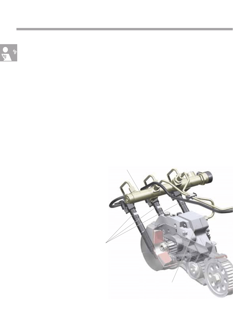
The 3.0l V6 TDI engine fitted in the Phaeton and
Touareg is equipped with a common rail fuel injection
system for mixture preparation.
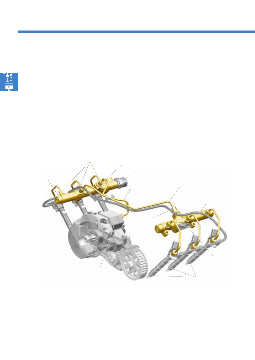
The common rail fuel injection system is a high-
pressure accumulator fuel injection system for diesel
engines.
The term "common rail" means that all of one cylinder
bank's injectors have a common, high-pressure fuel
accumulator.
High-pressure accumulator (rail), cylinder bank 1
High-pressure pump
Injectors
N30, N31, N32
In this injection system, pressure generation and fuel
injection are separate. The high pressure required for
injection is generated by a separate high-pressure
pump. This fuel pressure is stored in a high-pressure
accumulator (rail) and is made available to the
injectors via short injector pipes.
The common rail fuel injection system is controlled by
the Bosch EDC 16 CP engine management system.
Common rail fuel injection system
5
S351_064
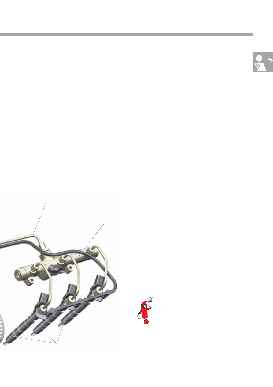
Injectors
N33, N83, N84
Connecting pipe between the
high-pressure accumulators (rails)
High-pressure accumulator (rail), cylinder bank 2
This fuel injection system's characteristics include:
●
The injection pressure can be selected almost
infinitely and can be adapted to the engine's
relevant operating status.
●
A high injection pressure up to a maximum of
1600 bar enables optimal mixture formation.
●
A flexible fuel injection process, with several pilot
and secondary injection processes.
The common rail fuel injection system offers many
options for adapting the injection pressure and the
injection process to the engine's operating status.
It therefore offers very good prerequisites for meeting
the constant increase in requirements pertaining to
low fuel consumption, low exhaust emissions and
smooth running characteristics.
Injectors are also referred to as injection
valves in the specialist literature. Due to
the electrical component designation in
the repair literature, they are called
injectors in the self-study programme.
6
Fuel system
High pressure 230 – 1600 bar
Return pressure from the injectors 10 bar
Supply pressure
Return pressure
Fuel filter
Fuel temperature sender G81
Pressure retention valve
Fuel metering valve N290
Mechanical
gear pump
Pre-heater valve
(expansion element)
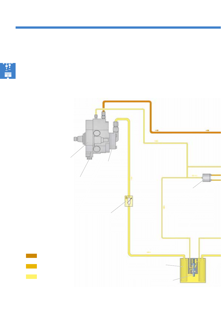
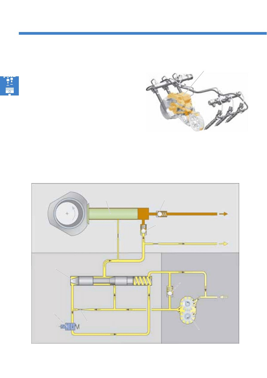
Overview of the system
The fuel system is sub-divided into three pressure
ranges:
●
High pressure 230 – 1600 bar
●
Return pressure from the injectors 10 bar
●
Supply pressure, return pressure
In the fuel supply system, the fuel is delivered to the
high-pressure pump from the fuel tank via the fuel
filter by the electric fuel pumps and the mechanical
gear pump. The high fuel pressure required for
injection is generated in the high-pressure pump and
is fed into the high-pressure accumulator (rail).
High-pressure pump
7
S351_005
1
2
3
4
5
6
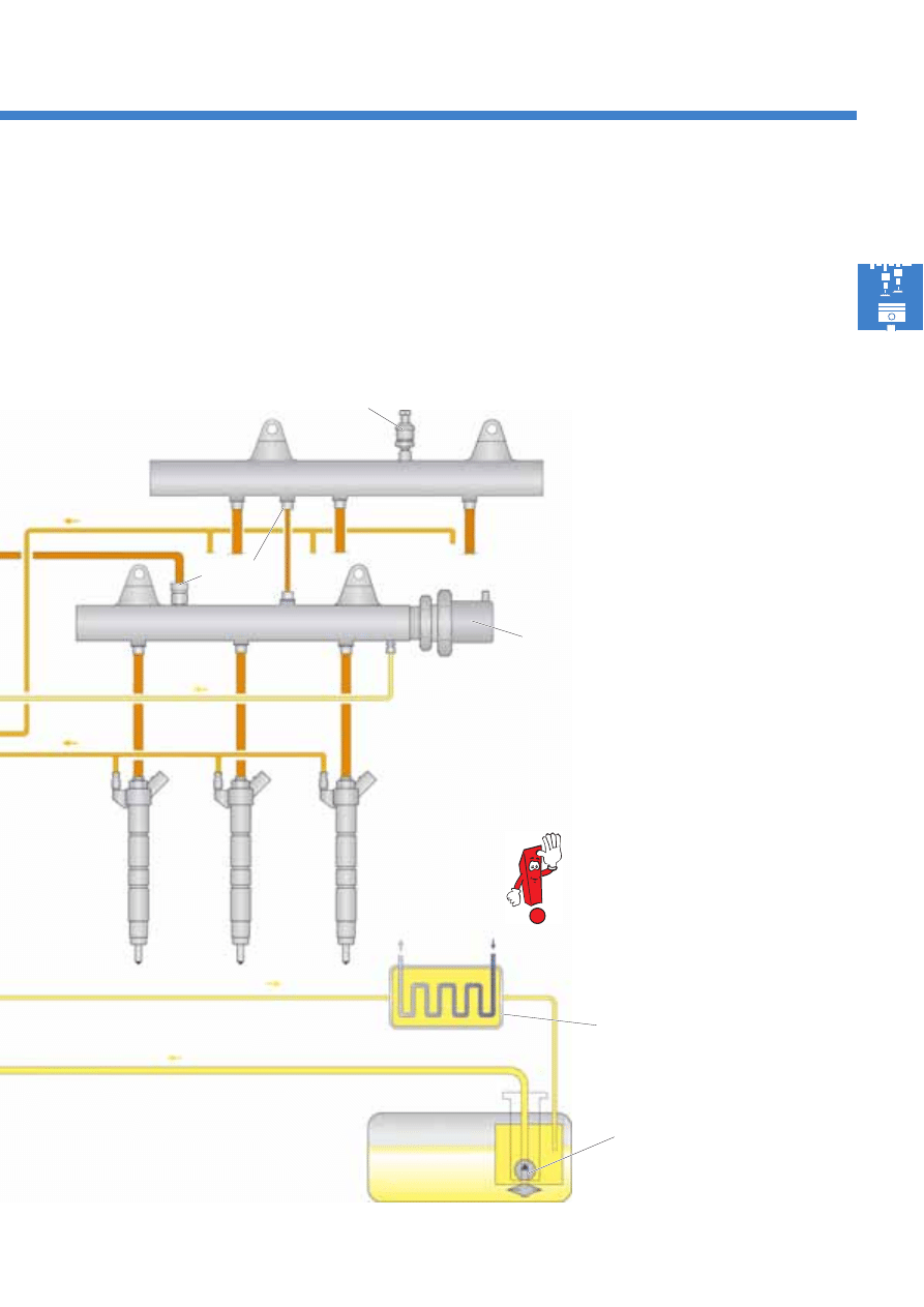
The pressure retention valve maintains the injectors'
return pressure at 10 bar. This pressure is required for
the piezo injectors' function.
From the high-pressure accumulator, the fuel is
forwarded to the injectors, which inject it into the
combustion chambers.
Piezo injectors 1 – 3
N30, N31, N32
High-pressure accumulator (rail), cylinder bank 2
High-pressure accumulator (rail), cylinder bank 1
Fuel system pressurisation pump G6,
fuel pump G23
Choke
Fuel pressure regulating
valve N276
Fuel tank
Fuel pressure sender G247
In the Phaeton, the returning fuel
is cooled by means of a fuel-air
cooler on the vehicle floor.
Fuel-coolant cooler
(Touareg)
8
S351_055
Fuel system
Effects in the event of failure
In the event of pump failure, a lack of fuel may lead to deviations in fuel pressure in the high-pressure accumulator
(rail) in combination with a fault memory entry. The engine's output is reduced.
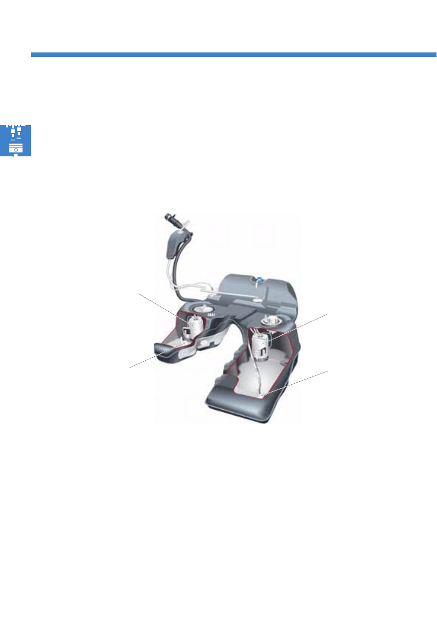
Fuel system pressurisation pump G6 and fuel pump G23
The two fuel pumps, G6 and G23, are installed in the fuel tank. They operate as pre-supply pumps for the
mechanical gear pump. The fuel tank fitted in the Touareg and the Phaeton is sub-divided into a left- and a right-
hand chamber.
When the ignition is switched on and the engine speed exceeds 40 rpm, the two electric fuel pumps are initialised
by the diesel direct injection system control unit J248 via the fuel pump relay J17, and build up pilot pressure.
As soon as the engine is running, both pumps continuously pump fuel into the fuel supply system.
The right-hand chamber's suction jet pump pumps the fuel into the pre-delivery tank for the fuel system
pressurisation pump G6, and the left-hand chamber's suction jet pump pumps fuel into the pre-delivery tank for the
fuel pump G23. Both suction jet pumps are driven by the electric fuel pumps.
●
The fuel system pressurisation pump G6 and a
suction jet pump are installed in the left-hand
chamber of the fuel tank.
●
The fuel pump G23 and a suction jet pump are
installed in the right-hand chamber.
Fuel system pressurisation
pump G6
Fuel pump G23
Suction jet pump
Suction jet pump
The illustration corresponds to the
fuel tank fitted in the Touareg
9
S351_065
S351_079
Fuel filter with pre-heater valve
The fuel filter protects the fuel injection system against
contamination and wear caused by particles and
water.
The centre fuel filter pipe contains a pre-heater valve,
which is comprised of an expansion element and a
spring-loaded plunger. Depending on the fuel
temperature, the pre-heater valve conducts the fuel
flowing back from the high-pressure pump, the high-
pressure accumulators and the injectors into the fuel
filter or to the fuel tank.
This prevents the fuel filter's becoming clogged via
paraffin crystal formation at low ambient
temperatures, thereby leading to malfunctions in
engine operation.
Supply to
high pressure
pump
Supply from
fuel tank
Supply from
fuel tank
Return to
fuel tank
Supply to
high-pressure pump
Return from
high-pressure pump
Return from
high-pressure pump
Return to
fuel tank
Centre fuel filter pipe
Expansion element
Filter
Plunger
Fuel temperature below 5 °C
At a fuel temperature of less than 5 °C, the expansion
element is completely contracted, and the plunger
seals the route back to the fuel tank with the aid of
spring force. As a result of this, the hot fuel flowing
back from the high-pressure pump, the high-pressure
accumulators and the injectors is fed to the fuel filter,
and the fuel located there is heated.
Fuel temperature over 35 °C
At a fuel temperature of more than 35 °C, the
expansion element in the pre-heater valve is
completely opened, releasing the route back to the
fuel tank. The hot, returning fuel flows directly into the
fuel tank.
10
S351_105
S351_104
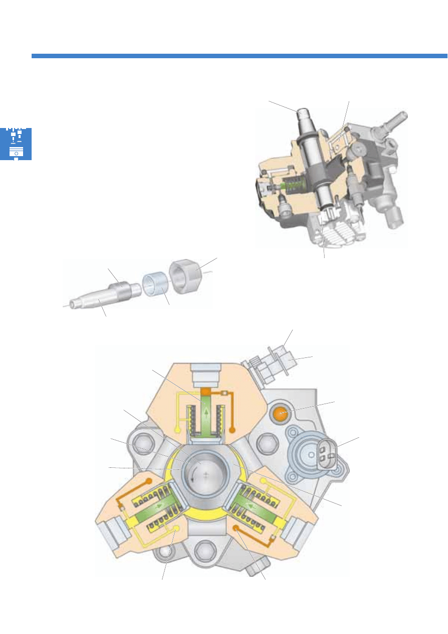
High-pressure pump with gear
pump
The high-pressure pump generates the high fuel
pressure required for injection. A gear pump, which
pumps the fuel into the high-pressure pump from the
fuel supply system, is integrated into the high-pressure
pump's housing.
Both pumps are driven by a common shaft. This shaft
is driven by the cylinder bank 2 inlet camshaft via a
toothed belt.
Fuel system
Schematic overview of the path taken by the fuel in the
high-pressure pump
Safety valve
Inlet from
fuel tank
Inlet valve
Outlet valve
Pump plunger
Control plunger
Choke bore
Fuel metering
valve N290
To high-pressure
accumulator
(rail)
Gear pump
High-pressure pump
with gear pump
Return to
fuel tank
11
S351_007
S351_086
Suction side
Pressure side
Drive gear
High-pressure pump
Drive shaft
Gear pump
Safety valve
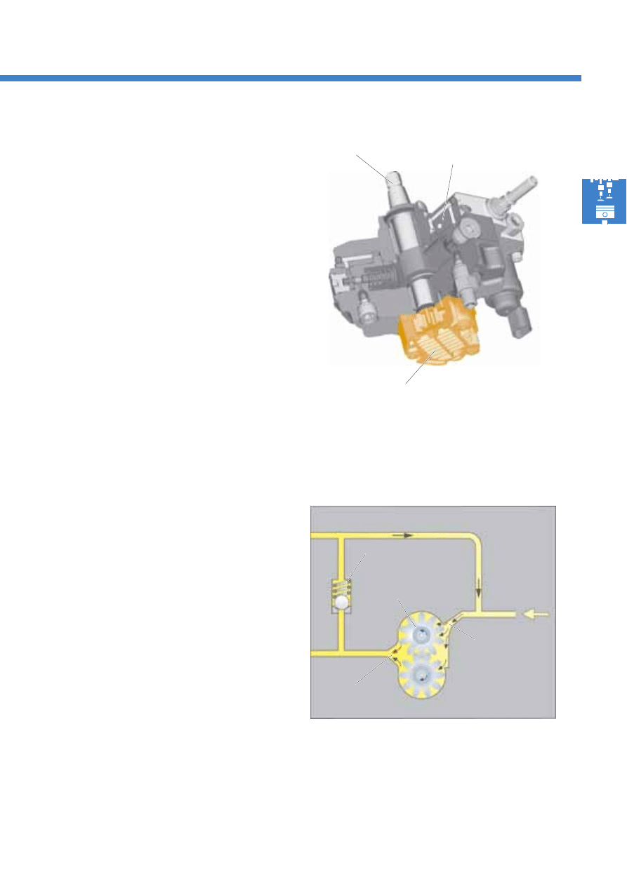
Gear pump
The gear pump is a purely mechanical pre-supply
pump. It is driven by the drive shaft together with the
high-pressure pump.
The gear pump increases the fuel pressure pre-
supplied by the two electric fuel pumps in the fuel
tank. This ensures that the high-pressure pump is
supplied with fuel in all operating statuses.
Design
Two counter-rotating gears are located in a housing,
whereby one gear is driven by the continuous drive
shaft.
Function
When the gears rotate, fuel is transported between
the tooth gaps and is delivered to the pressure side
along the inner wall of the pump.
From there, it is passed on to the high-pressure pump
housing. Intermesh between both gears' teeth
prevents the fuel from flowing back.
The safety valve opens when the fuel pressure on the
gear pump's pressure side exceeds 5.5 bar. The fuel is
then returned to the gear pump's suction side.
12
S351_011
S351_013
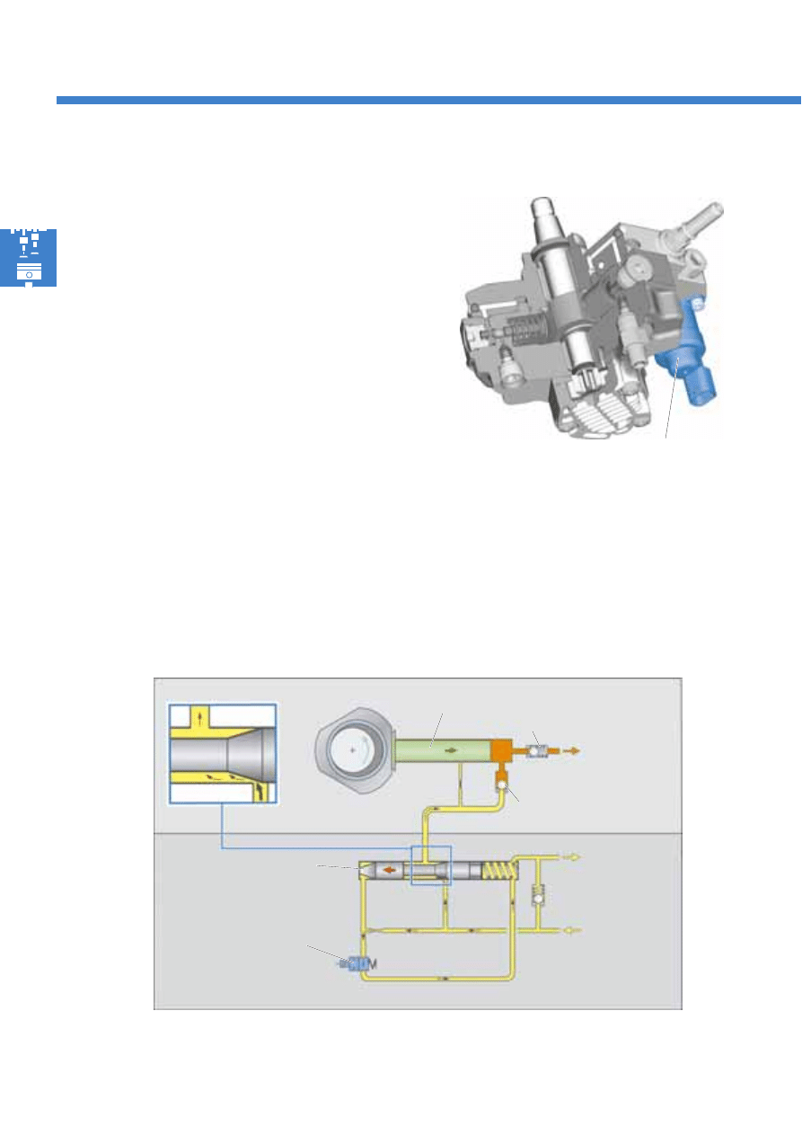
Fuel metering valve N290
The fuel metering valve is integrated into the high-
pressure pump.
It ensures that the fuel pressure is
regulated as required in the high-pressure area.
The fuel metering valve regulates the quantity of fuel
which flows to the high-pressure pump.
The advantage of this is that the high-pressure pump
only has to generate the pressure which is required
for the current operating situation. This reduces the
high-pressure pump's power consumption and avoids
unnecessary fuel heating.
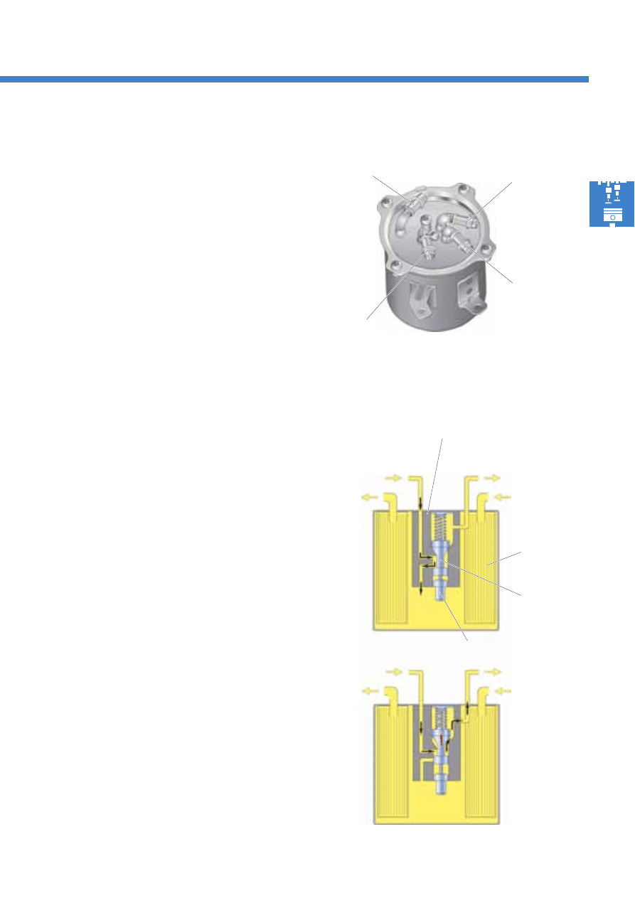
Fuel system
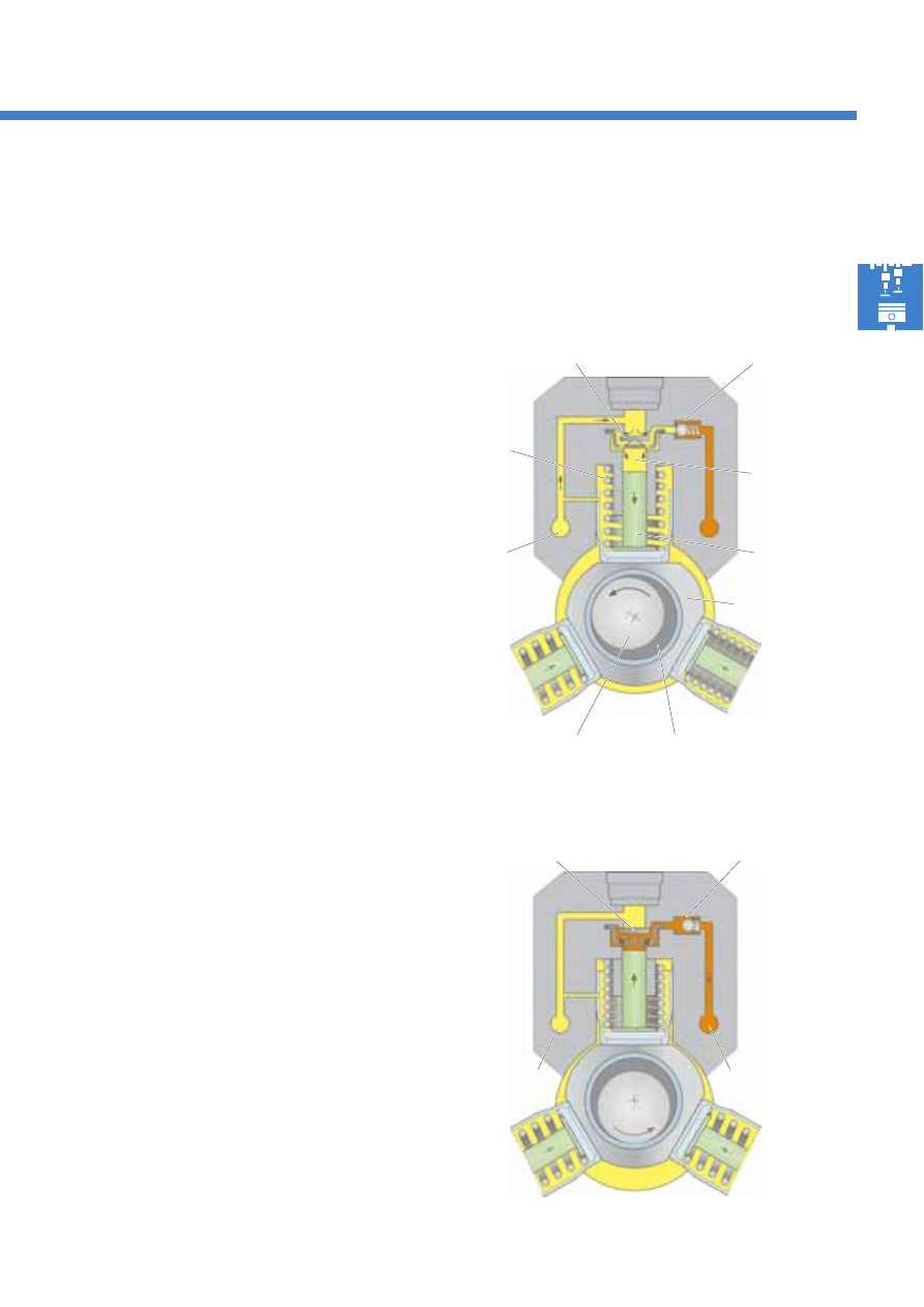
Fuel metering valve N290 function – without current
When no current is supplied, the fuel metering valve N290 is open. The control plunger is shifted to the left via the
spring force, and releases the minimal cross-section to the high-pressure pump. As a result of this, only a small
quantity of fuel enters the high-pressure pump's compression chamber.
Fuel metering
valve N290
Supply from
gear pump
Return to gear
pump
To high-pressure
accumulator
(rail)
Outlet valve
Control plunger
Fuel metering
valve N290
Pump plunger
Inlet valve
13
S351_088
S351_125
S351_124
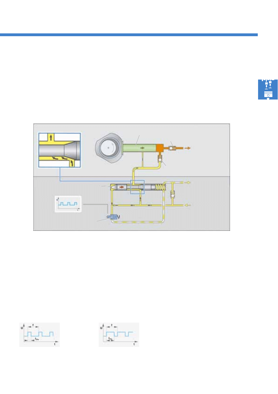
Fuel metering valve N290 function – initialised
To increase the quantity inlet to the high-pressure pump, the fuel metering valve N290 is initialised by the diesel
direct injection system control unit J248 using a pulse width modulated (PWM) signal.
Due to the PWM signal, the fuel metering valve is pulsed closed. This results in a control pressure, which acts on the
control plunger, downstream of the valve. Varying the on-off ratio changes the control pressure and therefore the
position of the plunger. The control pressure decreases and the control plunger is shifted to the right. This increases
the fuel inlet to the high-pressure pump.
Supply from
gear pump
Return gear
pump
To high-pressure
accumulator
(rail)
Effects in the event of failure
The engine's output is reduced. The engine management system operates in emergency running mode.
Short pulse width =
small fuel inlet
Outlet valve
Pump plunger
Inlet valve
Fuel metering
valve N290
U
Voltage
t
Time
f
Cycle duration (frequency)
t
Pw
Pulse width (on-time)
Large pulse width =
large fuel inlet
PWM signals
PWM signals are "pulse width modulated" signals.
These are square-wave signals with a variable on-
time and constant frequency. Changing the valve's
on-time for fuel metering, for example, enables the
control pressure and therefore the position of the
control plunger to be changed.
Control plunger
14
S351_062
S351_114
S351_009
High-pressure pump
The high-pressure pump is 3-cylinder radial piston
pump. It is driven by the drive shaft together with the
gear pump.
The high-pressure pump has the task of generating
the high fuel pressure of up to 1600 bar, which is
required for fuel injection.
Due to the three pump plungers, which are arranged
at intervals of 120°, the strain on the pump drive is
even and pressure fluctuations in the high-pressure
accumulator are minimised.
Fuel system
Gear pump
Drive shaft
High-pressure pump
Pump plunger
Fuel metering
valve N290
Drive shaft
Sliding bushing
Cam plate
High-pressure
connection
Supply
Return
Eccentric cam
Drive shaft
Sliding bushing
Cam plate
(polygonal disc)
Eccentric cam
Annular port from gear pump
Annular port to high-pressure connection
15
S351_073
S351_010
Function
An eccentric cam is located on the high-pressure pump's drive shaft. Via a cam plate, this cam causes three pump
plungers, which are arranged with radial offset of 120°, to move up and down.
Pressure
spring
Inlet valve
Eccentric cam
Delivery stroke
The pressure in the compression chamber increases
when the pump plunger begins to move upwards.
As a result of this, the inlet valve plate is pushed
upwards, sealing the compression chamber. Pressure
continues to be built up due to the plunger's moving
upwards. As soon as the fuel pressure in the
compression chamber exceeds the pressure in the
high-pressure area, the outlet valve opens and the
fuel enters the high-pressure accumulator via the
annular port.
Compression
chamber
Pump
plunger
Drive shaft
Cam plate
Outlet valve
Outlet valve
Annular port
from gear pump
Suction stroke
Downwards movement on the part of the pump
plunger leads to an increase in the volume of the
compression chamber. The fuel pressure within the
compression chamber falls as a result of this. Due to
the pressure exerted by the gear pump, fuel is now
able to flow into the compression chamber via the
inlet valve.
Annular port
from gear pump
Inlet valve plate
Annular port to
high-pressure
connection
16
S351_069
Fuel system
Function
The fuel in the high-pressure accumulator is constantly
at a high pressure. If fuel is drawn from the high-
pressure accumulator for injection, the pressure within
the high-pressure accumulator remains virtually
constant thanks to its large storage volume.
Design
Both high-pressure accumulators are spatially
separated. They are connected to each other by a
pipe. The fuel inlet connection from the high-pressure
pump, the connections to the injectors and the fuel
pressure regulating valve N276 are located on the
cylinder bank 1 high-pressure accumulator.
High-pressure accumulator (rail)
A high-pressure accumulator (rail) is fitted for each of the engine's cylinder banks. The high-pressure accumulator
is a forged steel pipe. It has the task of storing the fuel required for injection for all of the cylinders at high pressure.
Fuel pressure regulating valve N276
Fuel pressure
sender G247
High-pressure accumulator (rail)
cylinder bank 2
High-pressure pump
Choke
Connection pipe
Connection
to injectors
High-pressure
accumulator (rail)
cylinder bank 1
Injectors
Inlet from
high-pressure pump
The fuel inlet connections from the connection pipe,
the connections to the injectors and the fuel pressure
sender G247 are located on the cylinder bank 2 high-
pressure accumulator.
Pressure fluctuations, which arise due to the pulsating
fuel supply to the high-pressure accumulator via the
high-pressure pump, are compensated by the high-
pressure accumulator's large storage volume and a
choke in the fuel inlet from the high-pressure pump.
Choke
17
S351_014
S351_015
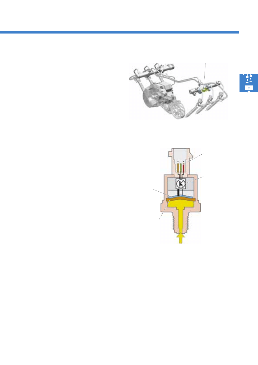
Fuel pressure sender G247
The fuel pressure sender is located on the cylinder
bank 2 high-pressure accumulator (rail). It determines
the current fuel pressure in the high-pressure area.
Function
The fuel pressure sender contains a sensor element,
which is comprised of a steel membrane with
expansion measuring strips.
The fuel pressure reaches the sensor element via the
high-pressure connection.
In the event of a change in pressure, the steel
membrane's deflection changes, as does the
resistance value of the expansion measuring strips.
The evaluation electronics calculate a voltage from
the resistance value and transmit this to the diesel
direct injection system control unit J248.
A characteristic curve stored in the control unit J248 is
used to calculate the current fuel pressure.
High-pressure connection
Evaluation
electronics
Expansion
measuring
strips
G247
Steel membrane
Effects in the event of signal failure
In the event of fuel pressure sender failure, the diesel direct injection system control unit J248 employs a fixed,
substitute value for calculation purposes. The engine's output is reduced.
Electrical
connection
18
S351_047
S351_074
Fuel system
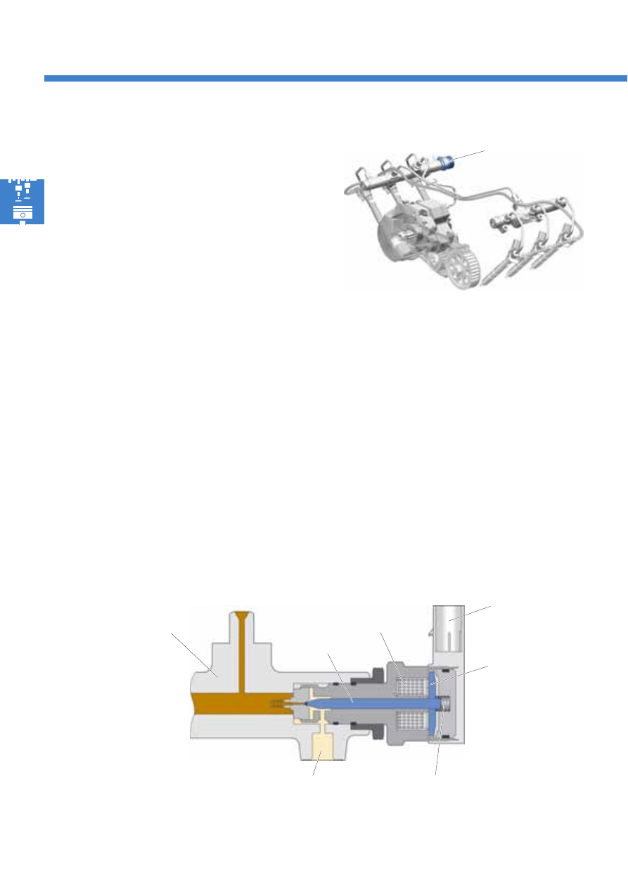
Fuel pressure regulating valve N276
The fuel pressure regulating valve is located on the
cylinder bank 1 high-pressure accumulator (rail).
The regulating valve is used to adjust the fuel pressure
in the high-pressure area. To do this, it is initialised by
the diesel direct injection system control unit J248.
Depending on the engine's operating status, the
pressure is between 230 and 1600 bar.
If the fuel pressure in the high-pressure area is too
high, the regulating valve opens, with the result that
some of the fuel in the high-pressure accumulator
enters the fuel tank via the fuel return.
If the fuel pressure in the high-pressure area is too
low, the regulating valve closes, thereby sealing the
high-pressure area at the fuel return.
Function
Regulating valve in resting position (engine "off")
If the regulating valve is not initialised, the valve needle is exclusively pressed into its seat via the force exerted by
the valve spring. The high-pressure area is separated from the fuel return in this case.
The valve spring is designed in such a way that a fuel pressure of approx. 80 bar is attained in the high-pressure
accumulator.
N276
Return to fuel tank
Valve needle
Valve spring
Solenoid
Electrical connection
Valve armature
High-pressure
accumulator (rail)
19
S351_087
S351_106
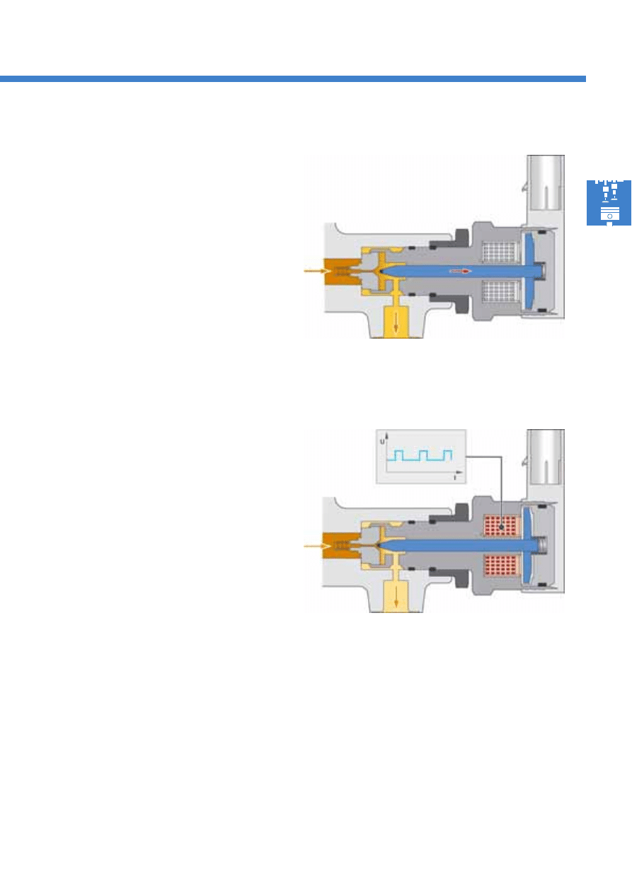
Regulating valve initialised (engine "on")
To attain an operating pressure of 230 to 1600 bar in
the high-pressure accumulator, the regulating valve is
initialised by the diesel direct injection system control
unit J248 using a pulse width modulated (PWM)
signal. This leads to a magnetic field in the solenoid.
The valve armature is picked up and presses the valve
needle into its seat.
The fuel pressure in the high-pressure accumulator is
therefore opposed by a magnetic force in addition to
the valve spring's force.
Depending on the on-off ratio of initialisation, the
flow cross-section to the return pipe and therefore the
quantity flowing off are varied.
This also enables pressure fluctuations in the high-
pressure accumulator to be compensated.
Regulating valve opened mechanically
If the fuel pressure in the high-pressure accumulator
is greater than the valve spring force, the regulating
valve opens and the fuel flows into the fuel tank via
the fuel return.
Effects in the event of failure
Engine operation is impossible in the event of fuel pressure regulating valve failure, as no fuel pressure which is
sufficiently high for fuel injection can be built-up.
20
S351_031
Fuel system
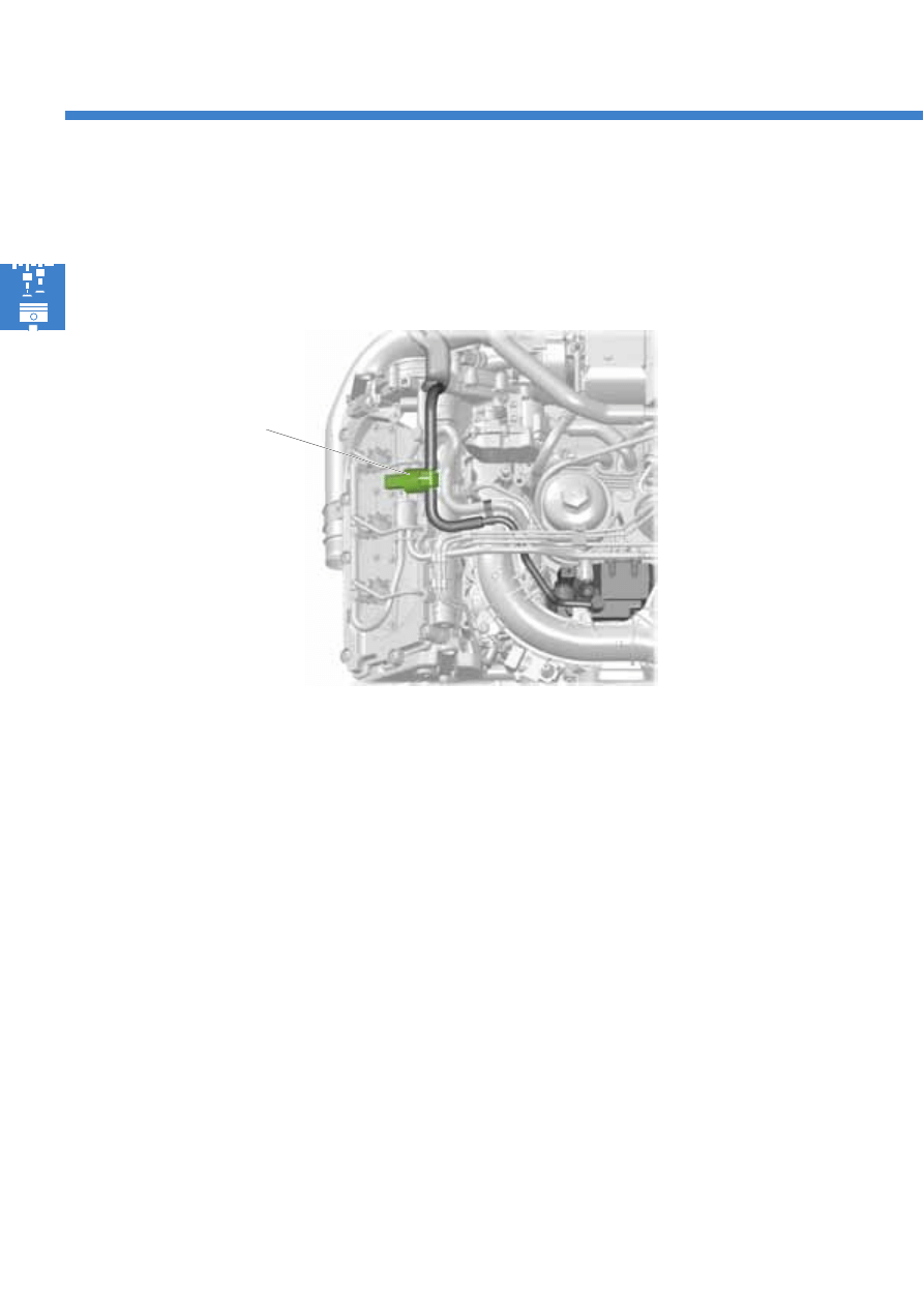
Fuel temperature sender G81
Signal usage
The diesel direct injection system control unit J248
uses the fuel temperature sender's signal to calculate
the fuel density. This serves as a correction variable to
calculate the injection quantity, to regulate the fuel
pressure in the high-pressure accumulator and to
regulate the quantity inlet to the high-pressure pump.
Fuel temperature sender G81
The fuel temperature sender is located in the fuel supply pipe to the high-pressure pump. The fuel temperature
sender is used to determine the current fuel temperature.
Effects in the event of signal failure
In the event of temperature sender failure, the diesel direct injection system control unit J248 employs a fixed,
substitute value for calculation purposes.
To protect the high-pressure pump against excessively
high fuel temperatures, the fuel temperature sender is
located in the fuel supply system. In the event of
excessively high temperatures in the fuel supply
system, the engine's output is limited in order to
protect the high-pressure pump. As a result of this, the
quantity of fuel to be compressed in the high pressure
pump is also indirectly reduced and the fuel
temperature is therefore lowered.
21
S351_090
S351_071
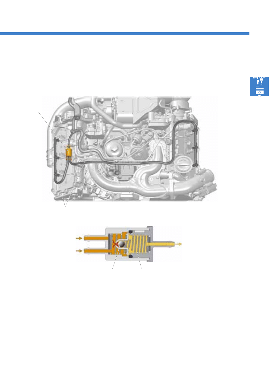
Task
The pressure retention valve maintains a fuel pressure
of approx. 10 bar in the injectors' fuel return. This fuel
pressure is required for the injectors' function.
Pressure retention valve
The pressure retention valve is a purely mechanical valve. It is located between the return pipes from the injectors
and the fuel system's fuel return.
Function
During engine operation, fuel flows from the injectors
to the pressure retention valve via the return pipes.
At a fuel pressure in excess of 10 bar, the ball is lifted
from its seat counter to the pressure spring's force.
The fuel flows through the open valve into the fuel
return to the fuel tank.
Pressure retention
valve
Fuel return pipe
Return to the
fuel tank
Pressure spring
Ball
Return from the
injectors
22
S351_016
S351_061
Fuel system
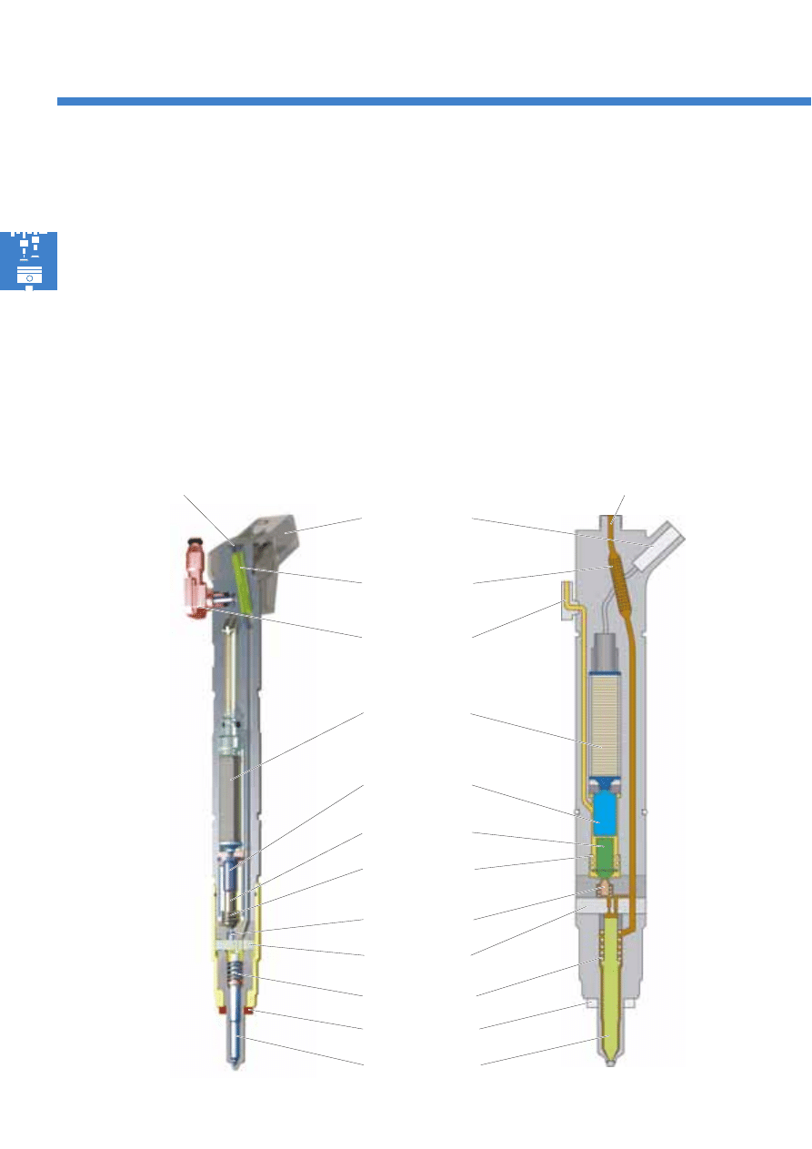
Piezo actuator
Pin-type filter
Switching valve
Choke plate
Connecting
plunger
Valve plunger
Valve plunger
spring
Fuel return
Fuel inlet (high-pressure connection)
Fuel inlet (high-pressure connection)
Injectors (injection valves)
The injectors are installed in the cylinder head.
They have the task of injecting the correct quantity of
fuel into the combustion chambers at the correct time.
The 3.0l V6 TDI engine is fitted with piezo-controlled
injectors. In this case, the injectors are controlled via
a piezo actuator. A piezo actuator's switching speed
is approximately four times faster than that of a
solenoid valve.
Electrical
connection
Nozzle spring
Injector needle
Sealing ring
Structure of an injector
In comparison with solenoid valve-controlled
injectors, piezo technology has approximately 75 %
less moved mass at the injector needle.
This results in the following advantages:
- Very short switching times
- Several injections per working cycle are possible
- Precisely apportionable injection quantities
23
S351_118
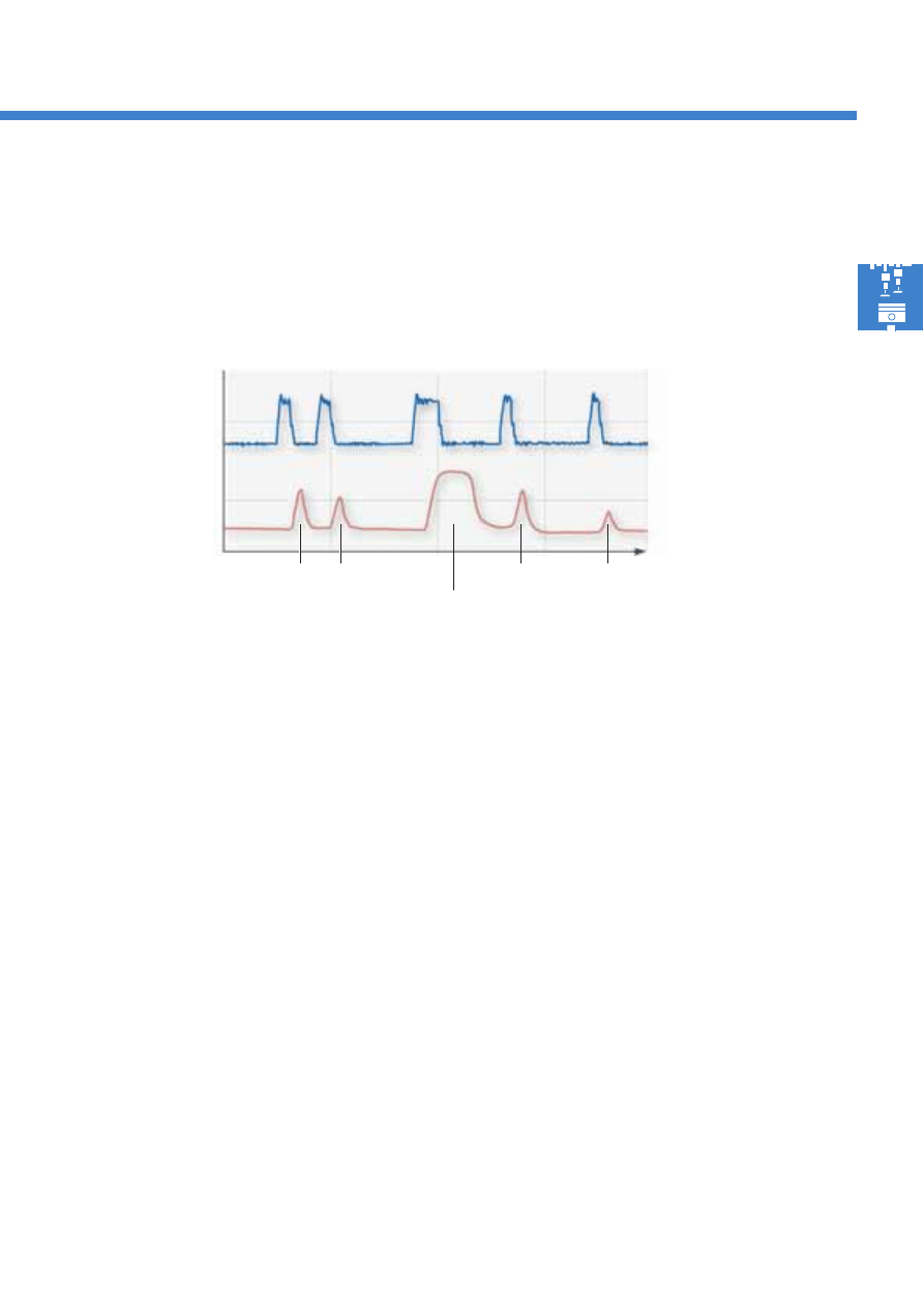
Pilot injection
A small quantity of fuel is injected into the combustion
chamber prior to main injection. This leads to a rise in
temperature and pressure in the combustion chamber.
The main injection ignition time lag is therefore
shortened, thereby reducing the rise in pressure and
pressure peaks in the combustion chamber. This leads
to low combustion noise and low exhaust emissions.
The number, time and injection quantities of the pilot
injection processes are dependent on the engine's
operating status.
When the engine is cold and at low engine speeds,
two pilot injections are carried out due to acoustic
reasons.
At higher loads and engine speeds, only one pilot
injection is carried out, in order to reduce exhaust
emissions.
No pilot injection is carried out at full throttle and
high engine speeds, because a large quantity of fuel
has to be injected to achieve a high level of efficiency.
Main injection
Following pilot injection, the main injection quantity
is injected into the combustion chamber following a
brief injection pause.
The injection pressure level remains virtually identical
throughout the entire injection process.
Secondary injection
Two secondary injection processes are carried out to
regenerate a diesel particulate filter. These secondary
injections increase the exhaust gas temperature,
which is necessary to combust the soot particles in the
diesel particulate filter.
Injection process
The piezo-controlled injectors' very short switching times enable flexible and precise control of the injection phases
and injection quantities. As a result of this, the injection process can be adapted to the engine's relevant operating
requirements. Up to five partial injections can be carried out per injection process.
Initialisation voltage
(V)
Injection
(rate of injection)
Pilot injection
Main injection
Time
Secondary injection
24
S351_017
S351_096
Fuel system
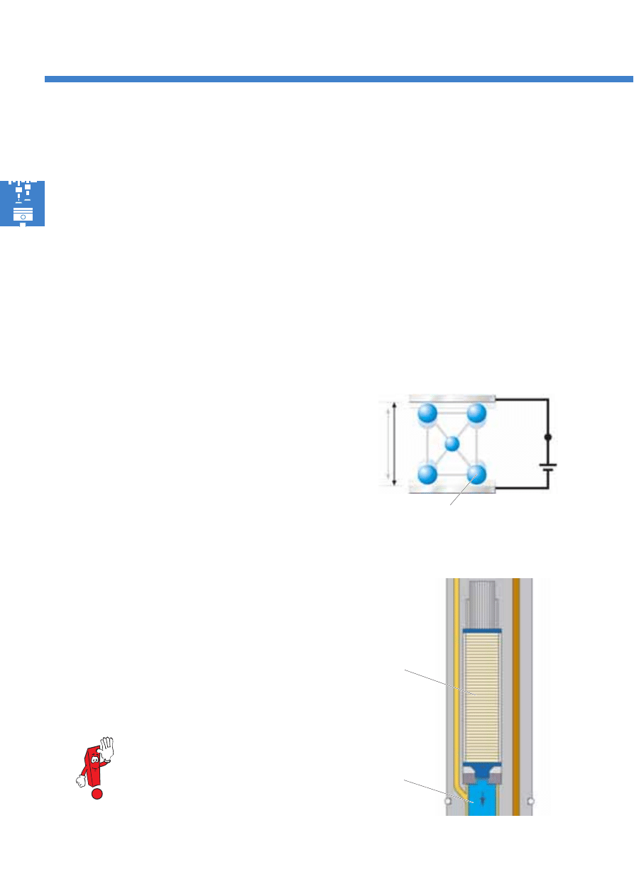
Piezo actuator
The piezo actuator is comprised of a multitude of
piezo elements, so that sufficiently extensive switching
travel for controlling the injector is achieved.
On application of a voltage, the piezo actuator
expands by up to 0.03 mm. (For comparison
purposes: A human hair has a diameter of
approximately 0.06 mm).
The piezo actuators are initialised with a
voltage of 110 – 148 V. Note the safety
instructions in the workshop manual.
Piezo elements
Connecting
plunger
Piezo actuator
A piezo actuator is used to control the injectors. This is located in the injector housing, and is initialised via the
diesel direct injection system control unit J248 electrical connection. The piezo actuator has a high switching speed,
switching in less than one ten-thousandth of a second. The inverse piezo-electric effect is used to control the piezo
actuator.
Piezo effect
Piezo (Greek) = pressure
Piezo elements are frequently used in sensor systems. In this case, pressure is applied to a piezo element, leading
to a measurable voltage. This behaviour on the part of a crystalline structure is called the piezo-electric effect.
Inverse piezo-electric effect
The piezo-electric effect is employed in reverse form
to use a piezo-controlled actuator. In this case, a
voltage is applied to the piezo element, and the
crystalline structure reacts by changing length.
Piezo element with voltage U
Initial length +
Change in length
Simplified
crystalline structure
25
S351_018
S351_108
Connecting
plunger
Valve
plunger
Switching
valve
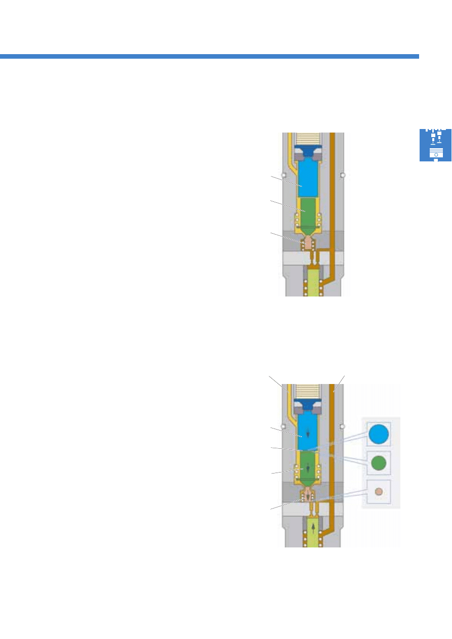
Connecting module in resting position
Connecting module
The connecting module is comprised of the connecting
plunger and the valve plunger. The connecting module
acts in the same manner as a hydraulic cylinder. It
hydraulically converts the piezo actuator's very rapid
longitudinal change and actuates the switching valve.
Thanks to hydraulic force transmission, switching valve
opening is dampened, and injection is therefore
precisely controlled.
Advantages of hydraulic force transmission
●
Low friction forces
●
Damping of moving components
●
Compensation of component longitudinal changes
caused by thermal expansion
●
No mechanical forces acting on the injector
needles
Connecting module actuated
Pressure
bolster
Area
ratios of the
plungers
Connecting
plunger
Valve
plunger
Switching
valve
Fuel return
High fuel pressure
Hydraulic principle
The connecting module is a hydraulic system, in which
both the forces and the plunger areas behave in
relation to each other.
In the connecting module, the area of the connecting
plunger is greater than the area of the valve plunger.
The valve plunger is therefore actuated by the
connecting plunger's force.
The area ratio of the connecting plunger to the
switching valve is several times higher. As a result
of this, the switching valve can be actuated by the
connecting module counter to the rail pressure.
The pressure retention valve in the fuel return
maintains a fuel pressure of approx. 10 bar in the
connecting module. This fuel pressure serves as a
pressure bolster for hydraulic force transmission
between the connecting plunger and valve plunger.
26
S351_019
Fuel system
Injector needle
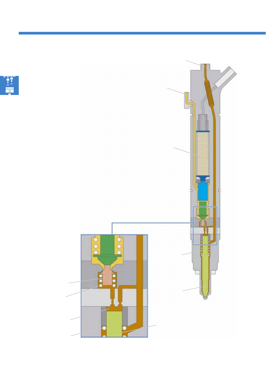
Injector in resting position
In its resting position, the injector is closed.
The piezo actuator is not initialised.
High fuel pressure is prevalent in the control chamber
above the injector needle and at the switching valve.
The switching valve is pressed into its seat by the high
fuel pressure and the switching valve spring's force.
The high fuel pressure is therefore separated from the
fuel return.
The injector needle is sealed by the high fuel pressure
in the control chamber above the injector needle and
the nozzle spring's force.
The pressure retention valve in the injectors' fuel
return maintains a fuel pressure of approx. 10 bar in
the fuel return.
Nozzle spring
Switching valve
spring
Nozzle spring
Injector needle
Switching valve
Control chamber
Piezo actuator
Fuel return
High fuel pressure
27
S351_020
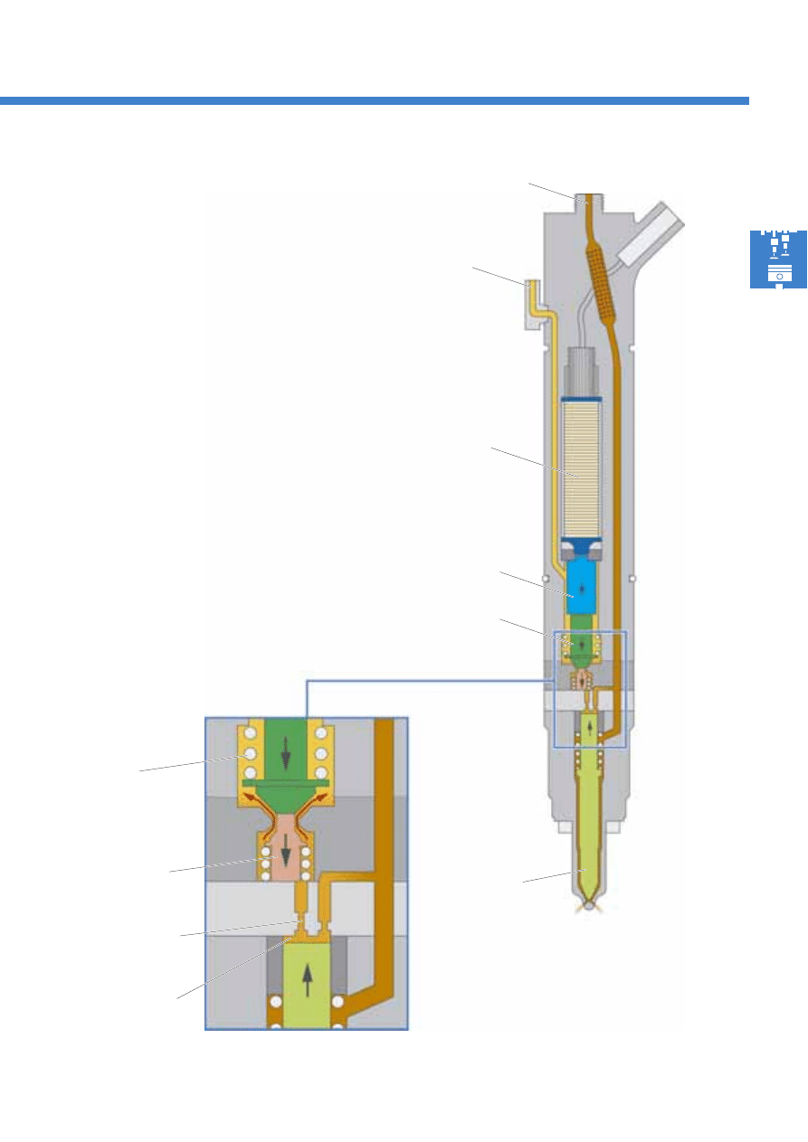
Start of injection
The start of injection is introduced by the diesel direct
injection system control unit J248. To do this, it ini-
tialises the piezo actuator.
The piezo actuator expands and transfers this
movement to the connecting plunger.
The connecting plunger's downwards movement
builds up a hydraulic pressure in the connecting
module, which acts on the switching valve via the
valve plunger.
The switching valve is opened due to the connecting
module's hydraulic pressure, and releases the path
from the high fuel pressure to the fuel return.
The fuel in the control chamber flows into the return
via the outflow choke. The fuel pressure above the
injector needle falls abruptly as a result of this. The
injector needle is raised, and injection begins.
Injector needle
Switching valve
Valve plunger
spring
Connecting plunger
Valve plunger
Outflow choke
Control chamber
Piezo actuator
Fuel return
High fuel pressure
28
S351_109
Fuel system
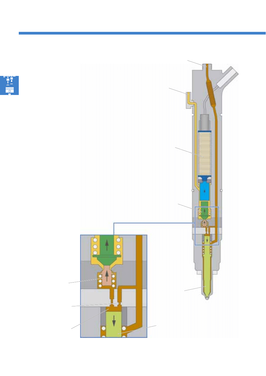
End of injection
The injection process ends when the piezo actuator is
no longer initialised by the diesel direct injection
system control unit J248. The piezo actuator returns to
its original position.
The connecting module's two plungers move upwards
and the switching valve is pressed into its seat. The
path from high fuel pressure to the fuel return is
therefore sealed. Fuel flows into the control chamber
above the injector needle via the inflow choke. The
fuel pressure in the control chamber increases to the
rail pressure again and closes the injector needle. The
injection process is completed, and the injector is in its
resting position again.
The injection quantity is determined by the piezo
actuator's initialisation duration and the rail pressure.
The piezo actuator's rapid switching times enable
several injections per working cycle and precise
adjustment of the injection quantity.
Injector needle
Valve plunger
Switching valve
Inflow choke
Control chamber
Injector needle
Piezo actuator
Fuel return
High fuel pressure
29
S351_117
Injector Delivery Calibration (IDC)
Injector delivery calibration (IDC) is a software
function in the diesel direct injection system control
unit J248 for initialising the injectors.
This function is used to individually correct the
injection quantity for each common rail fuel injection
system injector throughout the entire performance
map range. The precision of the fuel injection system
is improved as a result of this.
If an injector (injection valve) is renewed,
it must be matched to the fuel injection
system. Injector delivery calibration must
be carried out.
Please carry injector delivery calibration
out with the aid of guided fault finding!
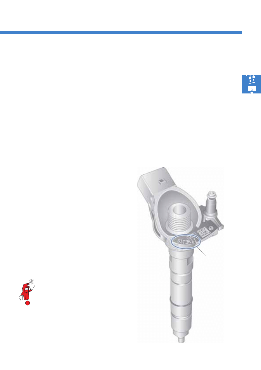
IDC value
A 7-digit calibration value is printed on each injector.
This calibration value may be comprised of letters
and/or numbers.
The IDC value is determined on a test rig during
injector production. It portrays the difference from the
nominal value, and therefore describes an injector's
fuel injection behaviour.
The IDC value enables the diesel direct injection
system control unit J248 to precisely calculate the
initialisation times required for injection for each
individual injector.
Thanks to injector delivery calibration, differences in
the injector's injection behaviour, which are caused by
production tolerances, are balanced out.
The objectives of this injection quantity correction are:
●
Reducing fuel consumption
●
Reducing the quantity of exhaust gas
●
Smooth running characteristics
Example of an IDC code on the injector
IDC value
30
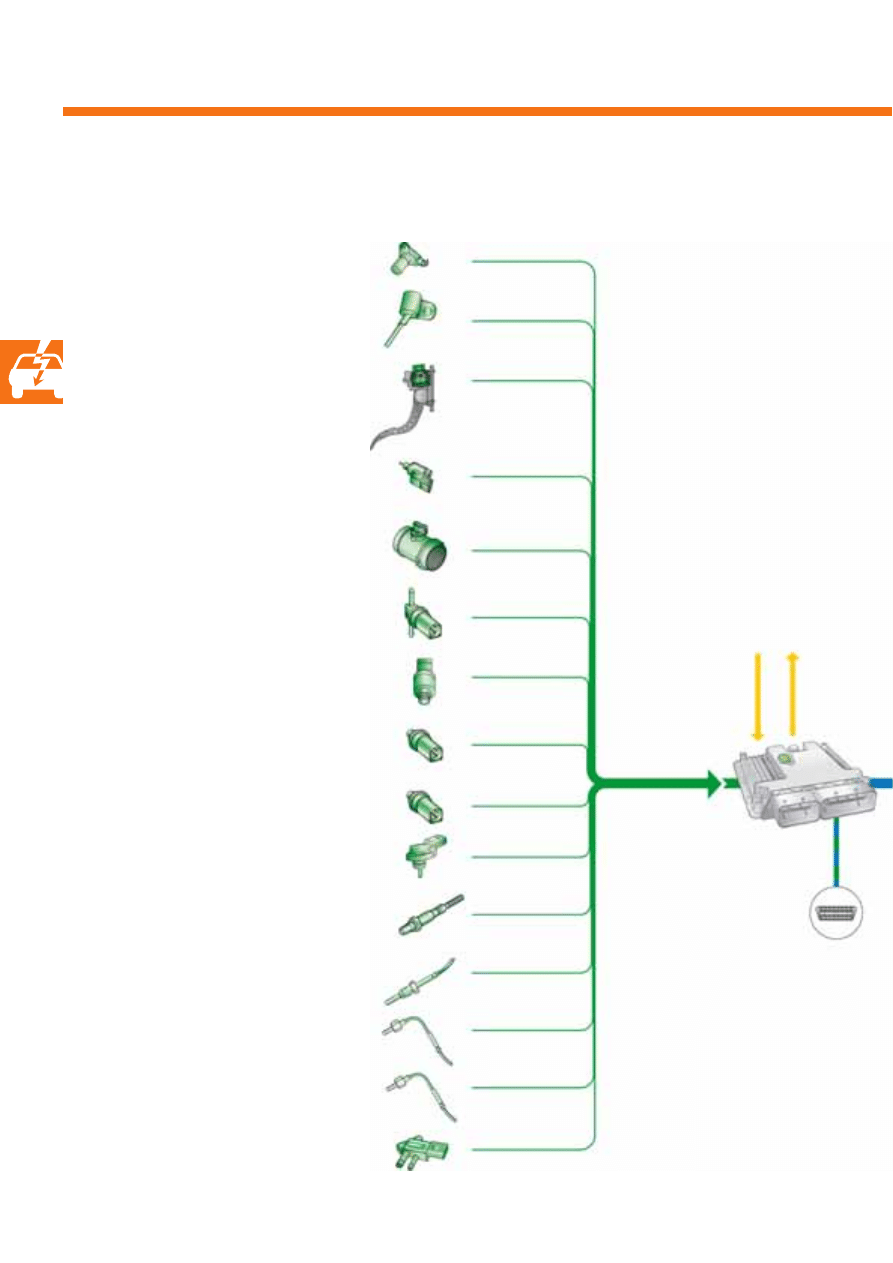
Engine management system
Overview of the system
Diesel direct injection
system control unit J248
Sensors
Drive CAN data bus
Air mass meter G70
Engine speed sender G28
Hall sender G40
Fuel temperature sender G81
Fuel pressure sender G247
Accelerator position sender G79
Accelerator position sender 2 G185
Kick-down switch F8
Catalytic converter temperature sensor 1 G20
(Phaeton only)
Exhaust gas temperature sender 1 G235
Bank 1 exhaust gas temperature sender 2 G448
Exhaust gas pressure sensor 1 G450
Charge air pressure sender G31
Intake air temperature sender G42
Coolant temperature sender G62
Radiator outlet coolant temperature
sender G83
Lambda probe G39
Brake light switch F
Brake pedal switch F47
Diagnostic
connection
This system overview
corresponds to the Phaeton.
31
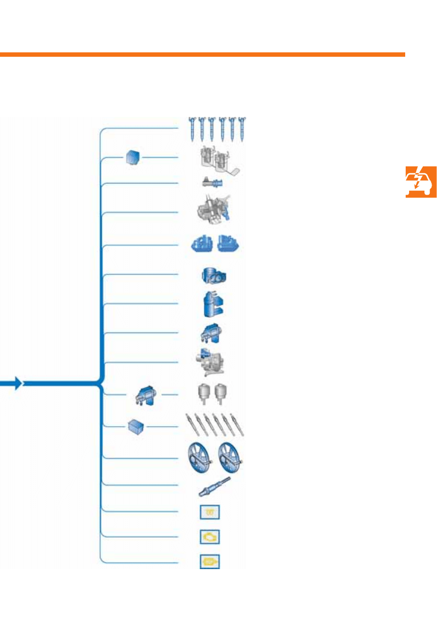
S351_053
Automatic glow period
control unit J179
Glow plugs 1 – 6
Q10, Q11, Q12, Q13, Q14 and Q15
Exhaust gas recirculation valve N18
Exhaust gas recirculation cooler change-
over valve N345
Radiator fan control unit J293
Radiator fan control unit 2 J671
Radiator fan V7
Radiator fan 2 V177
Fuel system pressurisation pump G6
Fuel pump G23
Lambda probe heater Z19
Turbocharger 1 control unit J724
Left electrohydraulic engine mounting
solenoid valve N144
Fuel pressure regulating valve N276
Throttle valve module J338
Intake manifold flap motor V157
Intake manifold flap 2 motor V275
Injectors for cylinders 1 – 6
N30, N31, N32, N33, N83 and N84
Fuel metering valve N290
Actuators
Glow period warning lamp K29
Exhaust emissions warning lamp K83
Diesel particulate filter warning lamp K231
Fuel pump relay J17
32
-
S351_115
Engine management system
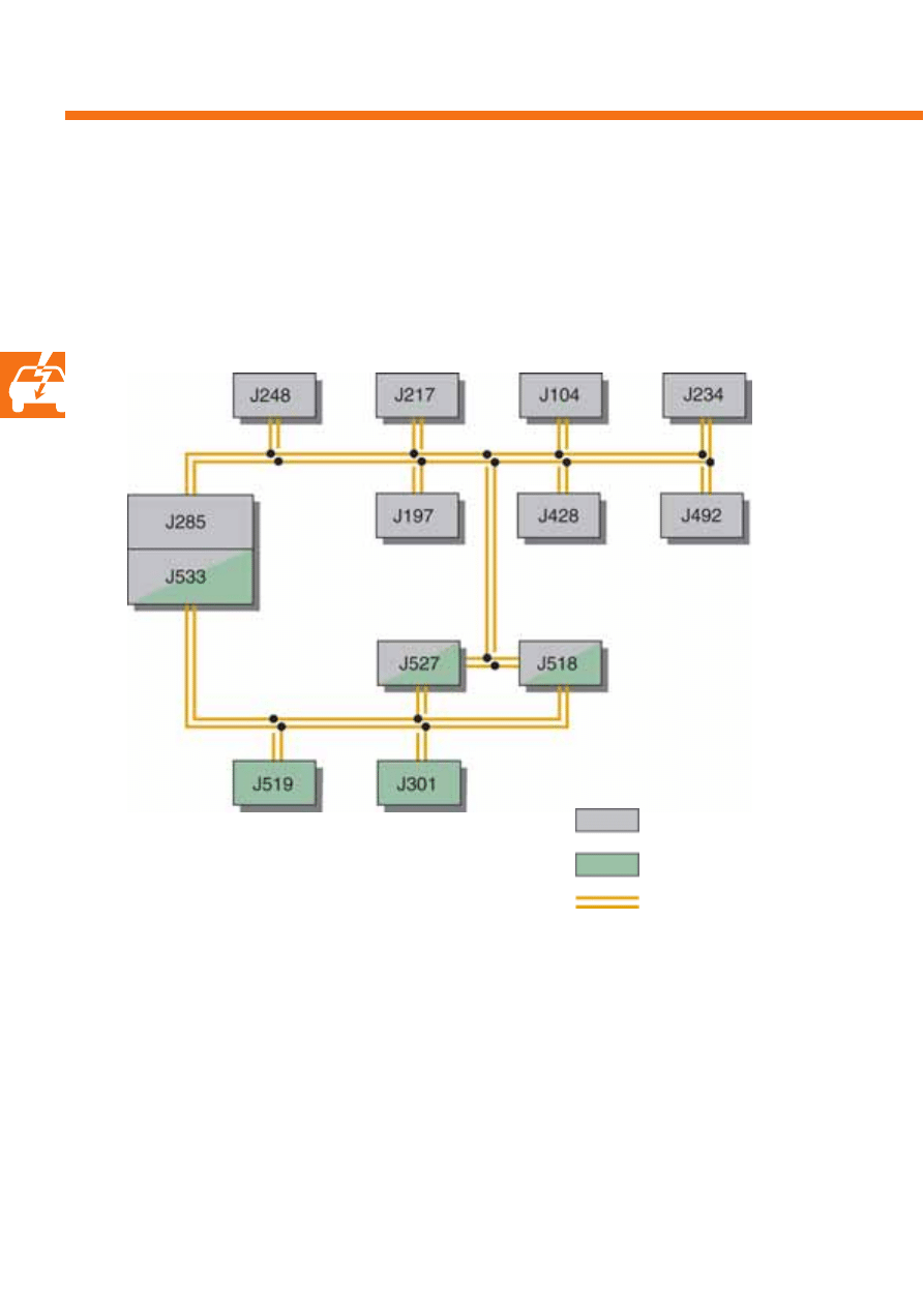
Control units in the CAN data bus
The schematic shown below shows the integration of the diesel direct injection system control unit J248 into the
vehicle's CAN data bus structure.
Information is transmitted between the control units via the CAN data bus. For example, the diesel direct injection
system control unit J248 receives the speed signal via the ABS control unit.
Drive CAN data bus
Convenience CAN data bus
CAN data bus line
Convenience CAN data bus
●
J285 Control unit with display in dash panel insert
●
J527 Steering column electronics control unit
●
J518 Entry and start authorisation control unit
●
J519 Onboard supply control unit
●
J301 Air conditioning system control unit
●
J533 Data bus diagnostic interface
Drive CAN data bus
●
J248 Diesel direct injection system control unit
●
J217 Automatic gearbox control unit
●
J104 ABS control unit
●
J234 Airbag control unit
●
J197 Adaptive suspension control unit
●
J428 Adaptive cruise control unit
●
J492 Four-wheel drive control unit

33
S351_022
S351_021
Signal usage
The engine speed and the precise position of the
crankshaft are recorded via the sender's signal. This
information is used by the diesel direct injection
system control unit J248 to calculate the injection
point and the injection quantity.
Effects in the event of signal failure
In the event of signal failure, the engine is shut off and
can no longer be started.
Signal usage
The sender signal is required by the diesel direct
injection system control unit J248 to detect the first
cylinder on starting the engine.
Effects in the event of signal failure
Starting the engine is impossible in the event of signal
failure.
Hall sender G40
Drive plate
Engine speed sender G28
Sender wheel
Segment gap
Sensors
Engine speed sender G28
The engine speed sender is secured to the gearbox housing. It is an inductive sender, which samples a 60-2 sender
wheel, which is secured to the drive plate. A segment gap on the sender wheel serves the engine speed sender as a
reference mark.
Hall sender G40
The hall sender is secured in the retaining frame of the cylinder bank 1 cylinder head. It scans the sender wheel on
the camshaft, with which the position of the camshaft is detected.
34
S351_056
S351_068
Engine management system
Signal usage
The accelerator position sender G79 and acceleration
position sender 2 G185 are used to detect the
position of the accelerator throughout the entire
adjustment range. These signals are used by the
diesel direct injection system control unit J248 to
calculate the injection quantity.
Effects in the event of signal failure
In the event that one of the two senders, G79 and
G185, fails, the system first switches to idle speed. If
the second sender is detected within a defined period
of time, vehicle operation becomes possible again.
However, the engine speed only increases slowly at
the desired full throttle.
In the event that both senders fail, the engine only
runs at increased idle speed, and no longer responds
to the accelerator.
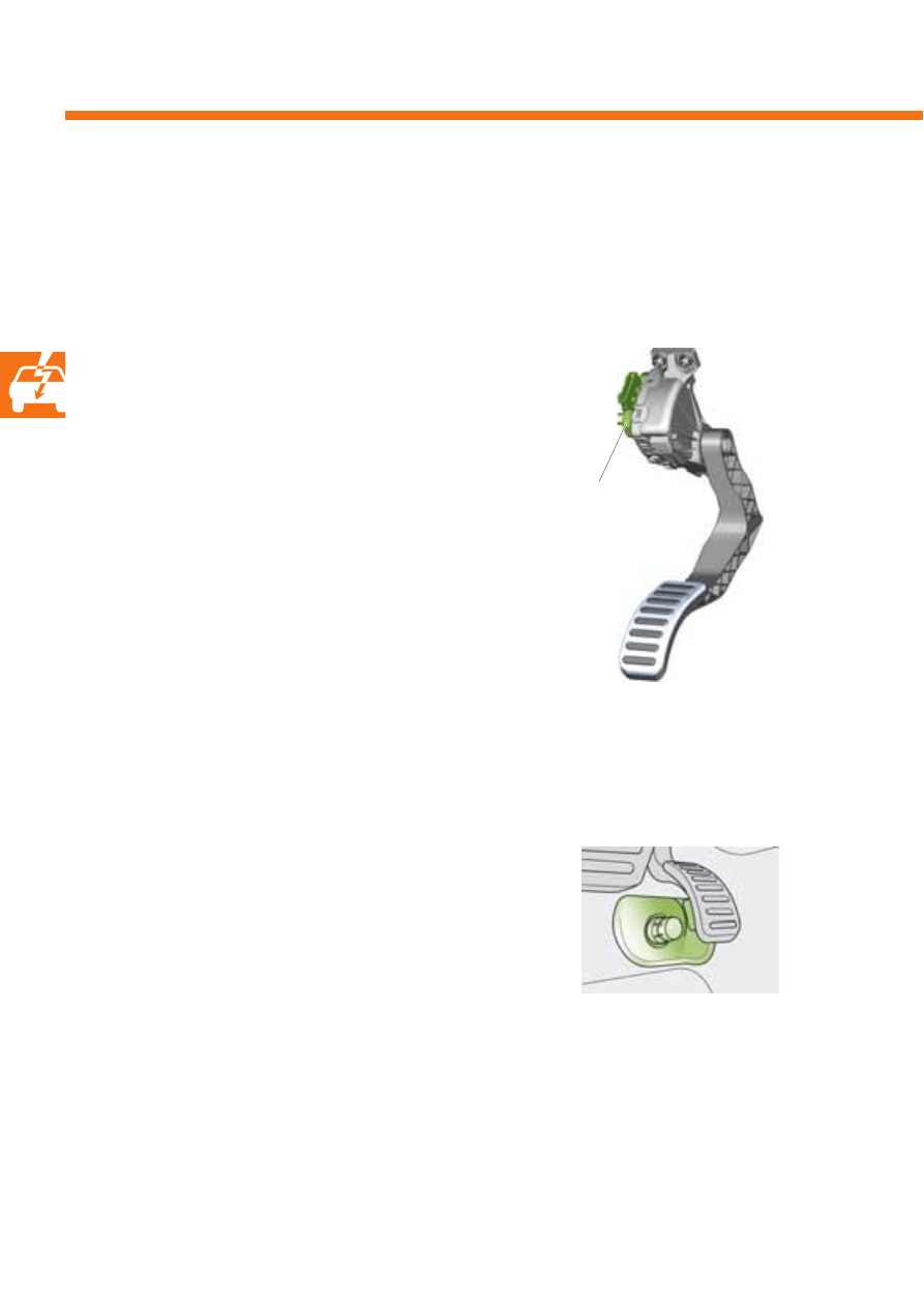
Accelerator pedal module
G79/G185/F8
Kick-down switch F8 in Phaeton
Accelerator position sender G79 and accelerator position sender 2 G185
The accelerator position sender G79 and accelerator position sender 2 G185 are comprised in one component and
integrated into the accelerator pedal module.
Kick-down switch F8
In the Phaeton, the kick-down switch is fitted as an
autonomous component on the floor panel beneath
the accelerator pedal module. In the Touareg, the
kick-down switch function is integrated into the
accelerator pedal module.
Signal usage
In addition to the accelerator position sender signals,
the kick-down switch signal serves the engine control
unit to detect the kick-down position. This information
is transmitted to the automatic gearbox control unit
via the drive CAN data bus, and the kick-down
function is carried out.
Effects in the event of signal failure
In the event of kick-down switch failure, the engine
control unit uses the accelerator position sender
values.
35
S351_025
S351_100
Clutch pedal
switch F36
Brake light switch F,
brake pedal switch F47
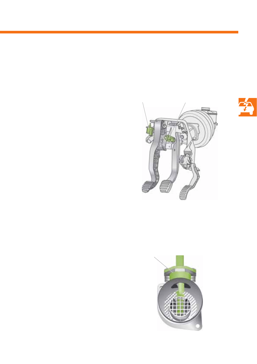
Signal usage
When the brake is actuated, the cruise control system
is shut off, and the engine no longer responds to the
accelerator pedal.
Effects in the event of signal failure
If a sender's signal fails, the injection quantity is
reduced and the engine has less output. The cruise
control system is additionally shut off.
Signal usage
The injection quantity and the exhaust gas
recirculation quantity are calculated by the diesel
direct injection system control unit J248 on the basis of
this signal. In connection with the diesel particulate
filter system, the signal is used to determine the diesel
particulate filter's soiling status.
Effects in the event of signal failure
In the event of signal failure, the diesel direct injection
system control unit J248 employs a substitute value
comprised of the charge air pressure and engine
speed for calculation purposes.
Air mass meter G70
Brake light switch F and brake pedal switch F47
The brake light switch F and the brake pedal switch F47 are located together in one component on the pedal
cluster. Both switches help the engine control unit to detect whether the brake is actuated.
Air mass meter G70
The air mass meter is located in the intake manifold. It works according to the hot film principle, and determines the
mass of air which is actually intaken.
36
S351_029
S351_089
Engine management system
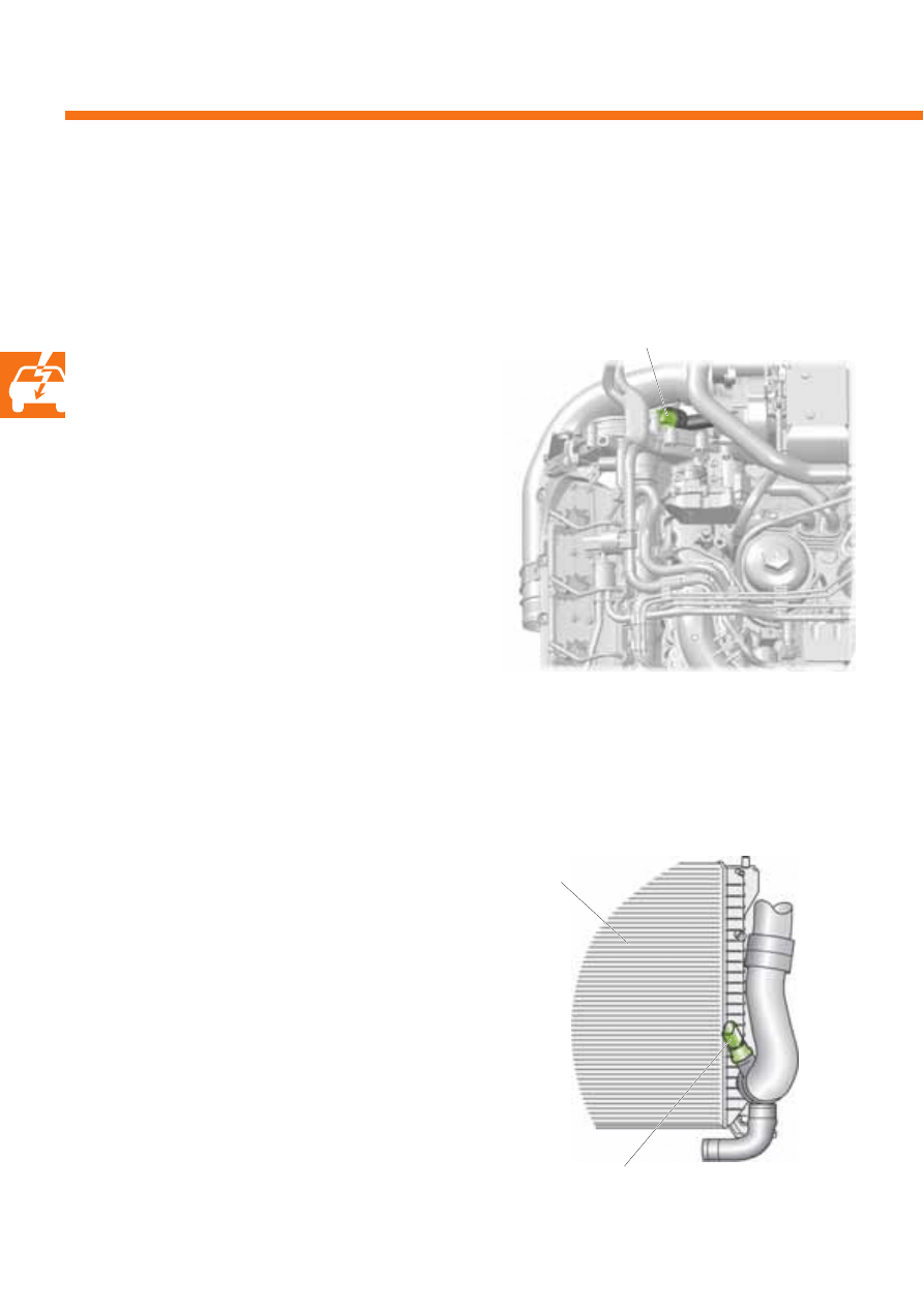
Radiator outlet coolant
temperature sender G83
Radiator
Coolant temperature sender G62
Coolant temperature sender G62
The coolant temperature sender is located on the right cylinder head's coolant connection.
The sender provides the diesel direct injection system control unit J248 with information on the current coolant
temperature.
Radiator outlet coolant temperature sender G83
The coolant temperature sender is located in the line at the radiator outlet, where it measures the outlet
temperature.
Signal usage
Radiator fan initialisation is carried out by comparing
the signals from the two senders, G62 and G83.
Effects in the event of signal failure
If the signal from the radiator outlet coolant
temperature sender G83 fails, radiator fan stage 1 is
continuously initialised.
Signal usage
The coolant temperature is used by the diesel direct
injection system control unit J248 as a correction
value for calculating the injection quantity, the charge
air pressure, the injection point and the exhaust gas
recirculation quantity.
Effects in the event of signal failure
If the sender signal fails, the diesel direct injection
system control unit J248 uses the signal from the
radiator outlet coolant temperature sender G83 and a
fixed, substitute value for calculation purposes.
37
S351_034
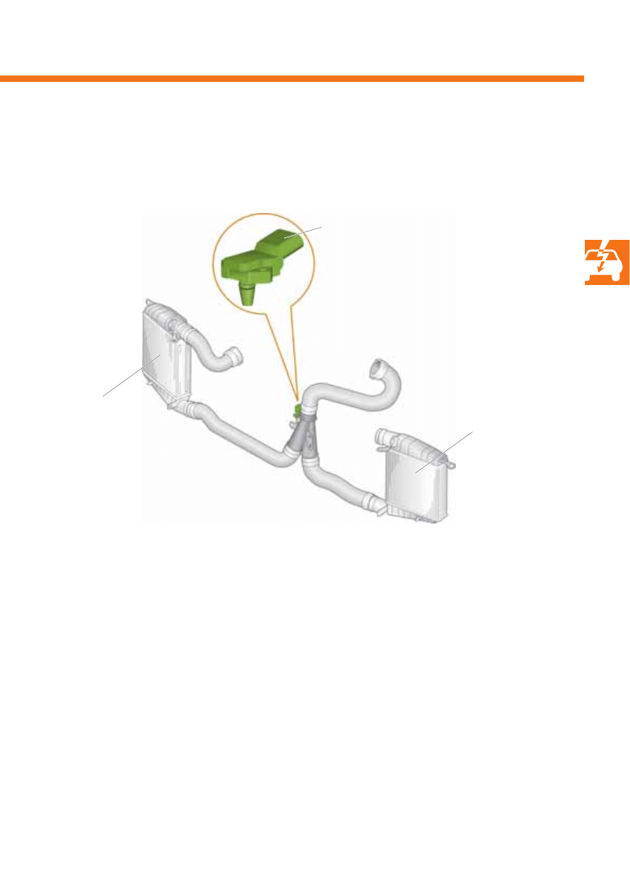
Charge air pressure sender G31
Signal usage
The diesel direct injection system control unit J248
uses the sender's signal to regulate the charge air
pressure.
Effects in the event of signal failure
There is no substitute function in the event of signal
failure. Charge air pressure regulation is shut off,
leading to a significant reduction in engine output.
Intake air temperature sender G42
Signal usage
The diesel direct injection system control unit J248
uses the sender's signal to calculate a correction
value for the charge air pressure. Evaluation of
the signal gives consideration to the influence of
temperature on the density of the charge air.
Effects in the event of signal failure
In the event of signal failure, the diesel direct injection
system control unit J248 employs a fixed, substitute
value for calculation purposes. This may lead to
reduced engine output.
Charge air pressure sender G31 and intake air temperature sender G42
The charge air pressure sender G31 and intake air temperature sender G42 are integrated into one component
and are located in the intake manifold.
G31/G42
The illustration corresponds to
installation in the Phaeton
Charge air cooler,
right-hand
Charge air cooler,
left-hand
38
S351_101
Lambda probe G39
A broadband lambda probe is located upstream of the oxidising catalytic converter in the exhaust system. The
lambda probe enables determination of the oxygen content in the exhaust gas over a wide measuring range.
Engine management system
Signal usage
The lambda probe's signal is used to correct the
exhaust gas recirculation quantity.
The signal also serves to determine the diesel
particulate filter's soiling status. In this calculation
model, the lambda probe signal is used to measure
the engine's carbon emissions. If the exhaust gas
oxygen content is excessively low in comparison with
the nominal value, increased carbon emissions are
concluded.
Information on the structure and function of a broadband lambda probe is available in
self-study programme 231.
Lambda probe G39
Oxidising catalytic
converter
Effects in the event of signal failure
If the signal fails, the exhaust gas recirculation quantity is determined using the air mass meter signal.
As this regulation is not so precise, nitrogen oxide emissions may increase.
Calculation of the diesel particulate filter's soiling status is less accurate. However, regeneration of the
diesel particulate filter remains reliable.
Turbocharger
39
S351_076
Exhaust gas
temperature
sender 1 G235
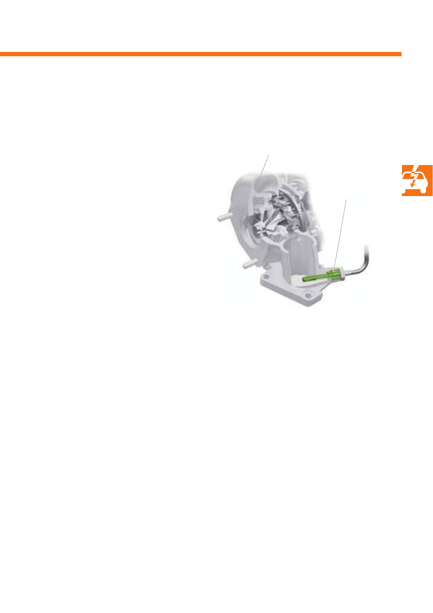
Signal usage
The diesel direct injection system control unit J248
uses the exhaust gas temperature sender's signal to
protect the turbocharger from impermissibly high
exhaust gas temperatures.
Turbocharger
Exhaust gas temperature sender 1 G235
Exhaust gas temperature sender 1 is a PTC sensor. It is located in the exhaust system upstream of the turbocharger,
where it measures the temperature of the exhaust gas.
Effects in the event of signal failure
If the exhaust gas temperature sender signal fails, the diesel direct injection system control unit J248 employs a
fixed, substitute value for calculation purposes, and engine output is reduced.
40
S351_091
Engine management system
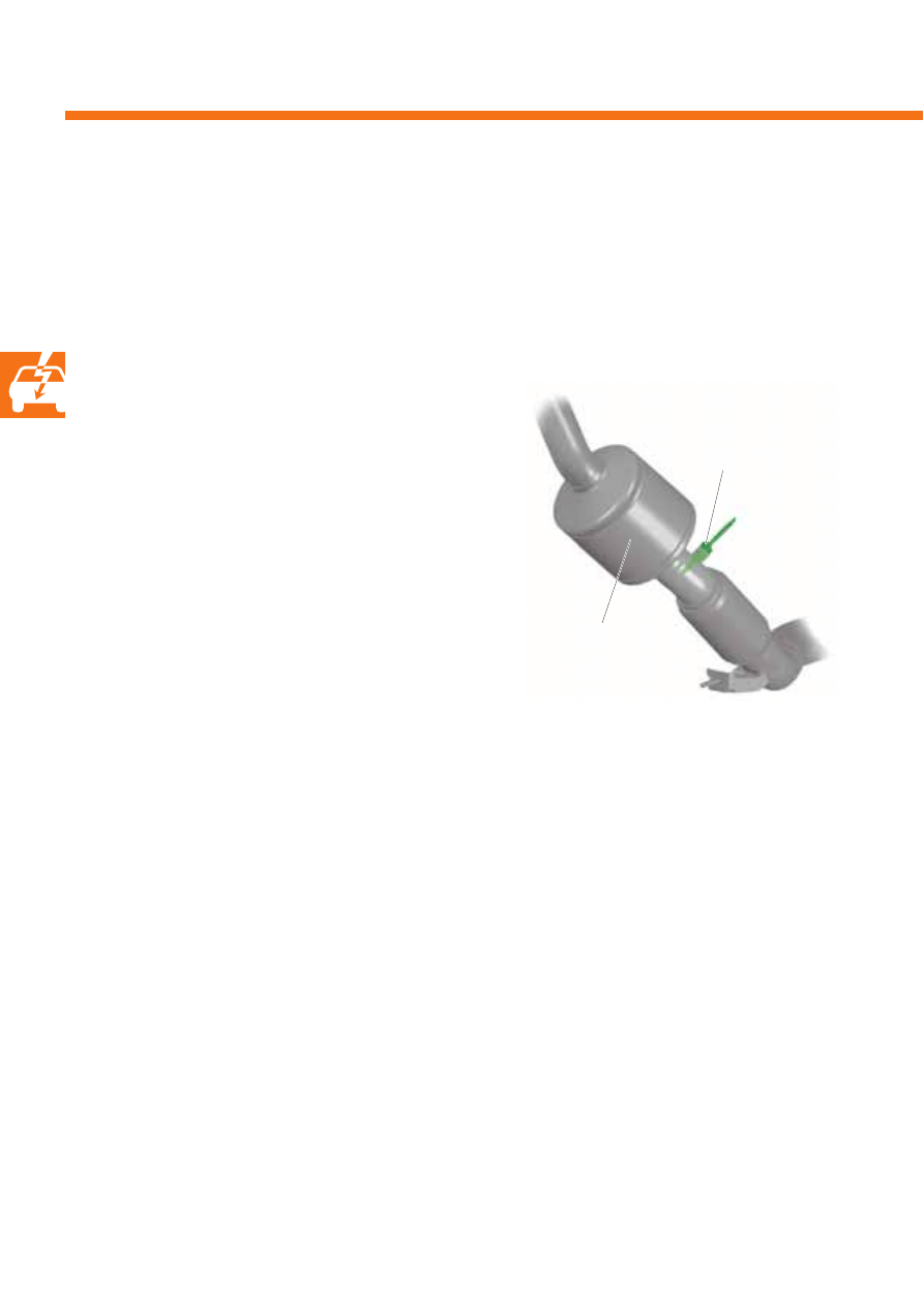
Signal usage
This signal is evaluated by the diesel direct injection
system control unit J248, and serves as a control
variable for secondary injection during the
regeneration phase.
The signal also serves as component protection, in
order to protect the catalytic converter from
excessively high exhaust gas temperatures.
In addition, the temperature information is used for
the calculation model to determine the diesel
particulate filter's soiling status.
Catalytic converter
temperature sensor 1 G20
Oxidising catalytic
converter
Catalytic converter temperature sensor 1 G20 (Phaeton only)
Catalytic converter temperature sensor 1 is a PTC sensor. It is located in the exhaust system directly downstream of
the oxidising catalytic converter, where it measures the temperature of the exhaust gas. Due to the long distance
between the catalytic converter and the diesel particulate filter, this sensor is only installed in the Phaeton.
Effects in the event of signal failure
If the temperature sensor signal fails, diesel particulate filter regeneration takes place according to the mileage
covered or hours of operation. The exhaust emissions warning lamp K83 is activated after three driving cycles.
41
S351_077
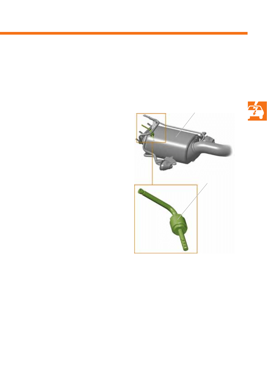
Signal usage
The diesel direct injection system control unit J248
uses the signal from bank 1 exhaust gas temperature
sender 2 to calculate the diesel particulate filter's
soiling status.
The diesel particulate filter's soiling status is
calculated using the signal from the bank 1 exhaust
gas temperature sender 2, together with the signals
from the exhaust gas pressure sensor, the air mass
meter and the lambda probe.
The signal also serves as component protection, in
order to protect the diesel particulate filter from
excessively high exhaust gas temperatures.
Diesel particulate filter
Bank 1 exhaust gas
temperature sender 2 G448
Bank 1 exhaust gas temperature sender 2 G448
Bank 1 exhaust gas temperature sender 2 is a PTC sensor. It is located in the exhaust system upstream of the diesel
particulate filter, where it measures the temperature of the exhaust gas.
Effects in the event of signal failure
If the bank 1 exhaust gas temperature sender 2 signal fails, diesel particulate filter regeneration takes place
according to the mileage covered or hours of operation. The exhaust emissions warning lamp K83 is activated after
three driving cycles.
42
S351_032
Engine management system
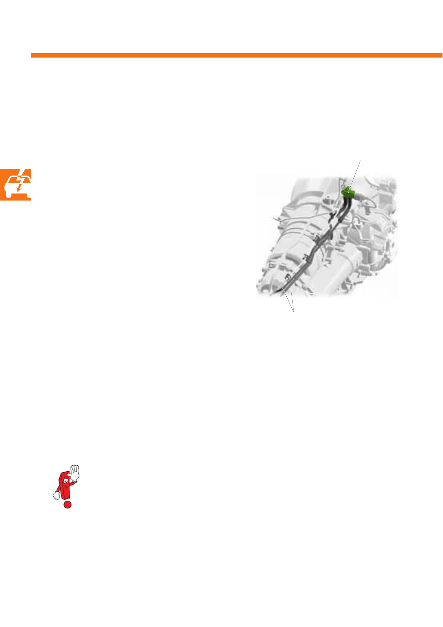
Signal usage
The diesel direct injection system control unit J248
uses the pressure sensor's signal to calculate the
diesel particulate filter's soiling status.
The diesel particulate filter's soiling status is
calculated using the exhaust gas pressure sensor
signal, together with the signals from the bank 1
exhaust gas temperature sender 2, the air mass meter
and the lambda probe.
Exhaust gas pressure sensor 1 G450
Exhaust gas pressure sensor 1 measures the difference in pressure in the flow of exhaust gas upstream and
downstream of the diesel particulate filter. It is secured to a bracket on the gearbox.
Effects in the event of signal failure
If the pressure sensor signal fails, diesel particulate filter regeneration takes place according to the mileage
covered or hours of operation. Glow period warning lamp K29 flashes at the same time. The exhaust emissions
warning lamp K83 is activated after three driving cycles.
Information on the structure and function of the pressure sensor can be found in self-study programme
336 "The catalytic coated diesel particulate filter".
Exhaust gas pressure sensor 1 G450
Connections from the
diesel particulate filter
43
S351_037
S351_122
Task
Continuously variable swirl flaps are located in the
lower sections of the intake manifolds of both cylinder
banks. The intaken air's swirl is adjusted via the
position of the swirl flaps, depending on the engine
speed and load.
The intake manifold flap motors have the task of
varying the position of the swirl flaps in the intake
ports by means of a push rod.
To do this, the intake manifold flap motors are
initialised by the diesel direct injection system control
unit J248.
The function of the intake manifold
flap motors is described in self-study
programme 350.
Intake manifold flap
motor V157
Intake manifold flap 2
motor V275
Actuators
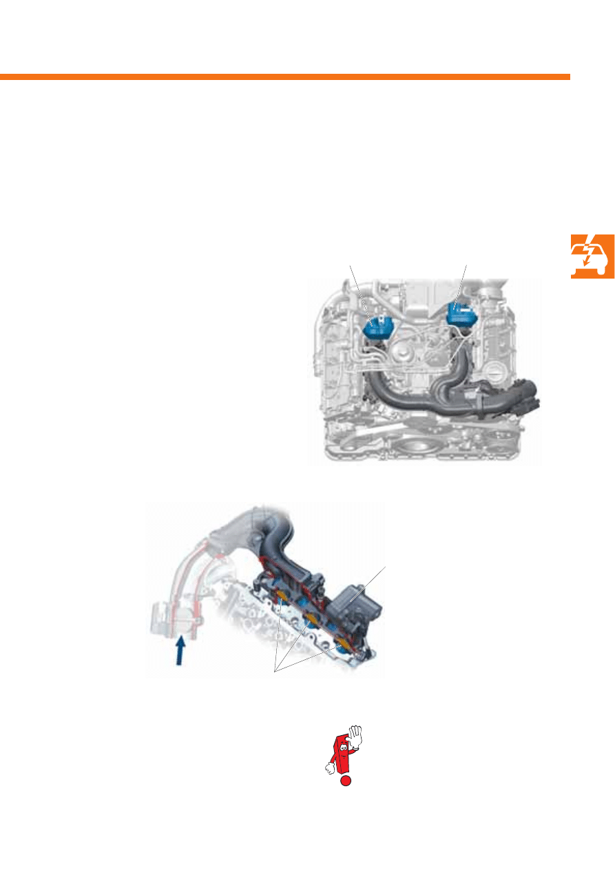
Intake manifold flap motor V157 and intake manifold flap 2 motor V275
The 3.0l V6 TDI engine has one intake manifold flap motor per cylinder bank. They are located on the lower section
of the intake manifold on the relevant cylinder bank.
Effects in the event of failure
If the intake manifold flap motors fail, the swirl flaps
remain open.
Intake manifold flap 2
motor V275
Intaken air
Swirl flaps
44
S351_123
S351_036
Engine management system
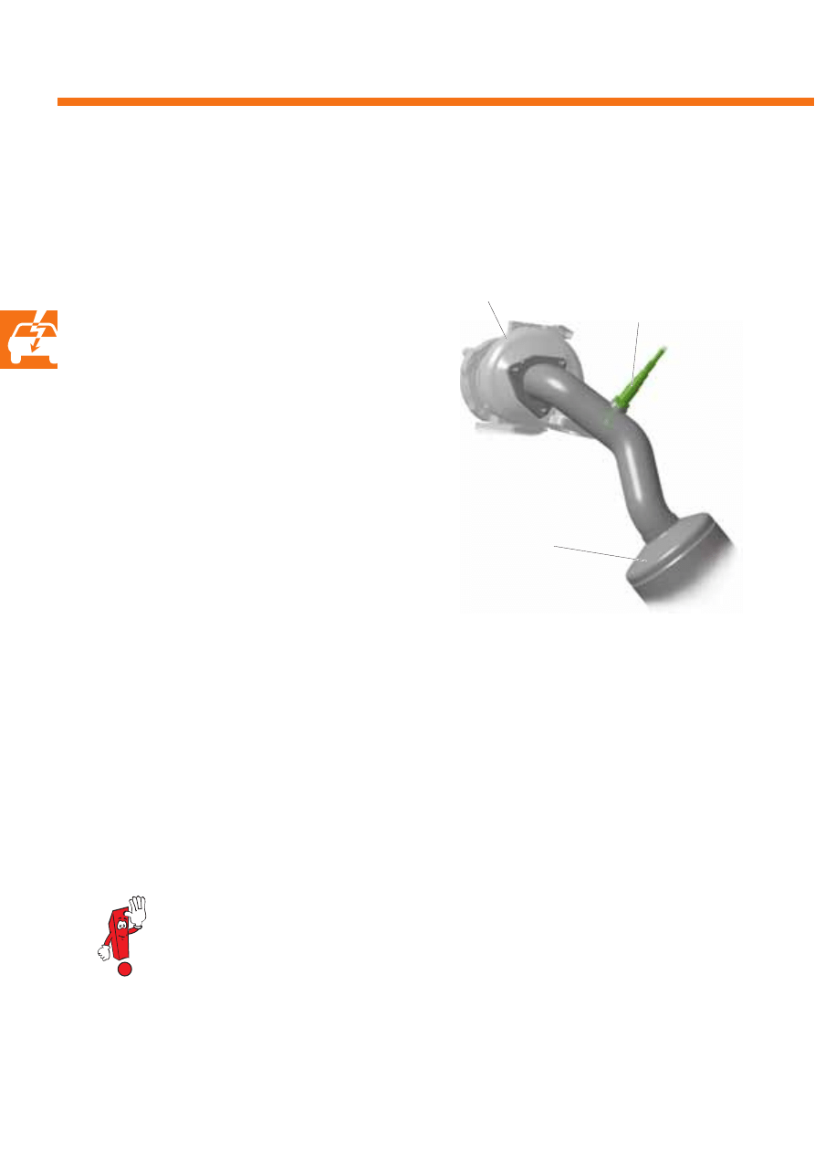
Task
The continuously variable throttle valve is used, in
specific operating statuses, to generate a vacuum
specified by the diesel direct injection system control
unit J248 in the intake manifold. Effective exhaust gas
recirculation is achieved as a result of this.
When the engine is switched off, the throttle valve is
closed and the air supply is interrupted. Less air is
therefore intaken and compressed, as a result of
which engine coasting is gentle.
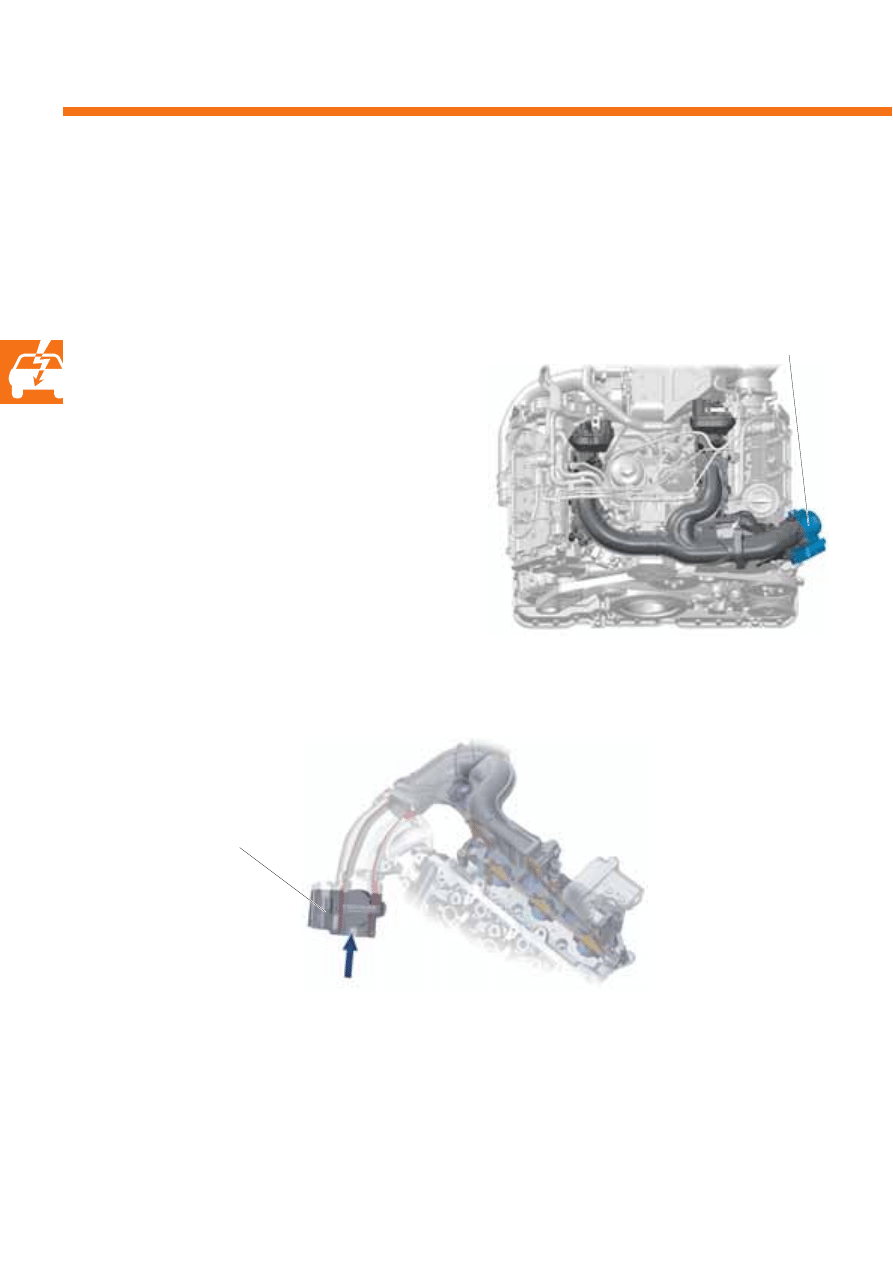
Throttle valve module J338
Throttle valve module J338
The throttle valve module is located in the intake port upstream of the upper section of the intake manifold. The
throttle valve in the throttle valve module is initialised via a positioning motor by the diesel direct injection system
control unit J248.
Effects in the event of failure
The throttle valve remains open. Correct regulation of the rate of exhaust gas recirculation is impossible.
Throttle valve module J338
Intaken air
45
S351_040
S351_099
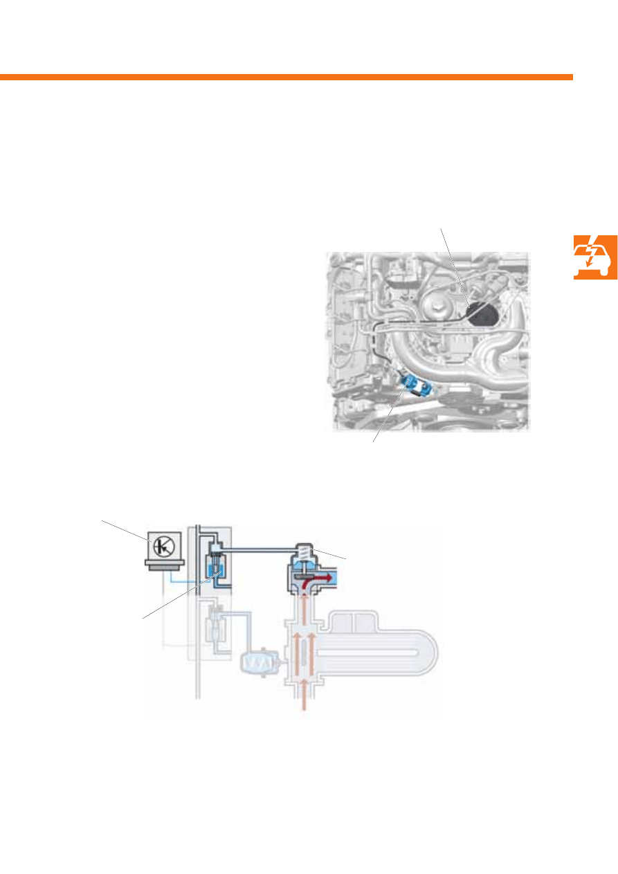
Task
The exhaust gas recirculation rate is determined by
means of a performance map in the diesel direct
injection system control unit J248. For control
purposes, the exhaust gas recirculation valve N18 is
initialised by the diesel direct injection system control
unit J248. The control pressure, with which the
mechanical exhaust gas recirculation valve is opened,
is determined depending on the signal on-off ratio.
Exhaust gas recirculation
valve N18
Exhaust gas
recirculation valve N18
Mechanical exhaust gas recirculation valve
Diesel direct injection
system control unit J248
Exhaust gas recirculation valve N18
The exhaust gas recirculation valve N18 is an electropneumatic valve. It switches the control pressure to actuate the
mechanical exhaust gas recirculation valve.
Effects in the event of failure
If the signal fails, the exhaust gas recirculation function is not guaranteed.
Mechanical
exhaust gas recirculation valve
46
S351_103
S351_049
Engine management system
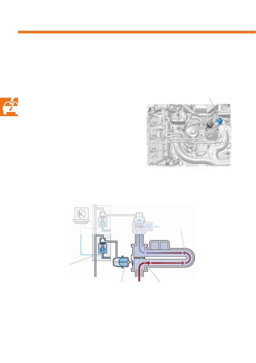
Exhaust gas recirculation
cooler change-over valve N345
Bypass valve
Exhaust gas
recirculation cooler
Exhaust gas recirculation
cooler change-over valve N345
Vacuum unit
Task
In order to reduce nitrogen oxide emissions even more
effectively, the recirculated exhaust gases are
conducted through the exhaust gas recirculation
cooler when the engine is at operating temperature.
The bypass valve in the exhaust gas recirculation
cooler is actuated to achieve this. The change-over
valve is initialised by the diesel direct injection system
control unit J248 depending on the temperature.
This then switches the vacuum unit's control pressure
to actuate the bypass valve in the exhaust gas
recirculation cooler.
Exhaust gas recirculation cooler change-over valve N345
The exhaust gas recirculation cooler change-over valve is an electropneumatic valve. It switches the vacuum unit's
control pressure to actuate the bypass valve in the exhaust gas recirculation cooler.
Effects in the event of failure
If the changeover valve fails, the exhaust gas recirculation cooler bypass valve remains closed. The exhaust gas is
always cooled, and both the engine and the oxidising catalytic converter take longer to reach their operating
temperature.
47
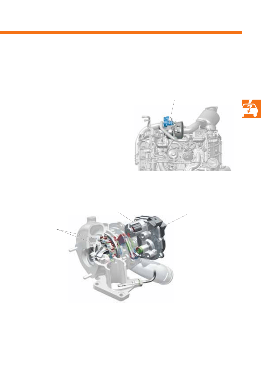
Task
The turbocharger 1 control unit controls guide vane
adjustment in the turbocharger via an electric
positioning motor. Electric initialisation makes fast
turbocharger response behaviour and precise
regulation possible.
To adjust the guide vanes, the turbocharger 1 control
unit is initialised by the diesel direct injection system
control unit J248 using a pulse width modulated
(PWM) signal.
S351_041
S351_092
Turbocharger 1 control unit J724
The turbocharger 1 control unit is located on the turbocharger.
Turbocharger 1
control unit J724
Positioning motor
Turbocharger 1
control unit J724
Effects in the event of failure
No further charge air pressure control is possible in the event of turbocharger 1 control unit failure. The injection
quantity is limited and engine output is reduced.
Guide vanes
48
S351_080
S351_102
Engine management system
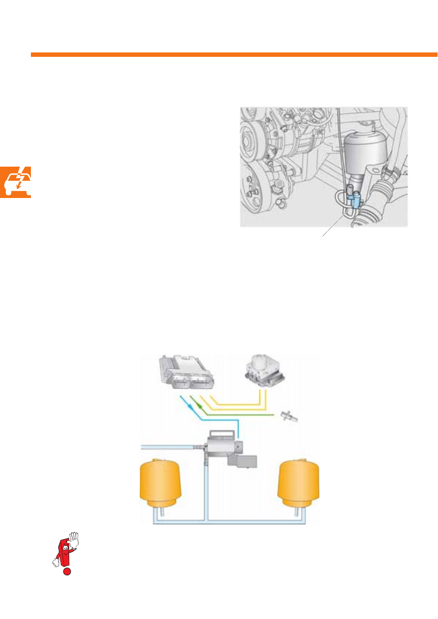
ABS control
unit J104
Engine speed sender G28
Left electrohydraulic engine
mounting solenoid valve N144
Engine
mounting,
right-hand
Engine
mounting,
left-hand
Left electrohydraulic engine
mounting solenoid valve N144
Diesel direct injection
system control unit J248
Detailed information on the electrohydraulic engine mounting can be found in
self-study programme 249 "The W8 engine management system in the Passat".
The left electrohydraulic engine mounting solenoid
valve is an electropneumatic valve. It is located on the
engine bracket on the left-hand side of the engine
compartment.
Task
The 3.0l V6 TDI engine fitted in the Phaeton is
equipped with hydraulically damped engine
mountings. These engine mountings reduce the
transmission of engine vibrations to the body, and
thereby ensure a high level of ride comfort.
The electrohydraulic engine mounting solenoid valve
is used to switch the control pressure for both engine
mountings.
Function
The left electrohydraulic engine mounting solenoid valve N144 is initialised by the diesel direct injection system
control unit J248 in order to change the engine mountings' damping characteristics. The solenoid valve then
switches the control pressure for both engine mountings. The vehicle speed and the engine speed are used as input
signals by the diesel direct injection system control unit J248.
Left electrohydraulic engine mounting solenoid valve N144
49
S351_113
S351_111
S351_112
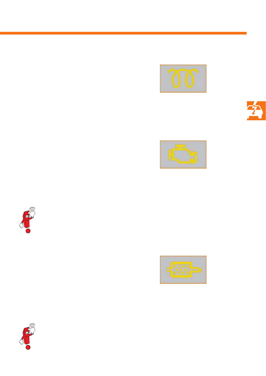
Glow period warning lamp K29
The glow period warning lamp has two functions:
●
It lights up to indicate the glow period to the driver
prior to starting the engine.
●
It flashes to notify the driver of an engine
malfunction.
Those engine management system components
relevant to exhaust emissions are checked as regards
failure and malfunctions within the framework of
European On-Board Diagnosis (EOBD).
The exhaust emissions warning lamp (MIL = Mal-
function Indicator Lamp) indicates faults detected by
the EOBD system.
Detailed information on the exhaust emissions warning lamp and the EOBD system can be found in
self-study programme 315 "European On-Board Diagnosis for diesel engines".
The diesel particulate filter warning lamp lights up
if the diesel particulate filter can no longer be
regenerated as a result of operation over extremely
short distances.
Via this signal, the driver is requested to drive as
evenly as possible at increased speed for a short
period of time, so that the diesel particulate filter can
be regenerated.
For precise information on driving behaviour when the diesel particulate filter warning lamp lights up,
please refer to the vehicle owner's manual.
Diesel particulate filter warning lamp K231
Exhaust emissions warning lamp K83 (MIL)
50
S351_098
Engine management system
Glow plug system
The 3.0l V6 TDI engine is fitted with a diesel quick-
start glow plug system.
This enables immediate starting, like that of a petrol
engine, without a long glow period under practically
all climatic conditions.
Advantages of this glow plug system
●
Reliable starting at temperatures down to –24 °C
●
Extremely rapid heating time – within two
seconds, a temperature of 1000 °C is reached at
the glow plug
●
Controllable glow and post-start glow temperature
●
Self-diagnosis-capable
●
European On-Board Diagnosis
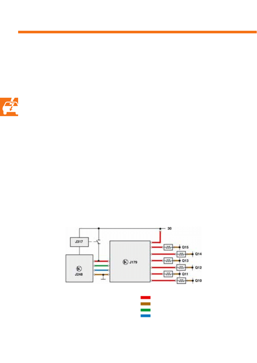
The automatic glow period control unit is provided with
information by the diesel direct injection system control
unit J248 for the glow function. The glow period, the
glow duration, the initialisation frequency and the on-
off ratio are therefore determined by the engine control
unit.
Automatic glow period control unit functions
●
Switching the glow plugs with a PWM signal
●
Integrated overvoltage and overtemperature shut-off
●
Individual plug monitoring
- Detection of overcurrent and short-circuit in the
glow circuit
- Glow circuit overcurrent shut-off
- Glow electronics diagnosis
- Detection of an open glow circuit in the event of
glow plug failure
J179
Automatic glow period control unit
J248
Diesel direct injection system control unit
J317
Terminal 30 voltage supply relay
Q10–Q15 Glow plugs
Supply voltage
Earth
Control signal from J248
Diagnostic signal to J248
51
S351_119
S351_120
S351_121
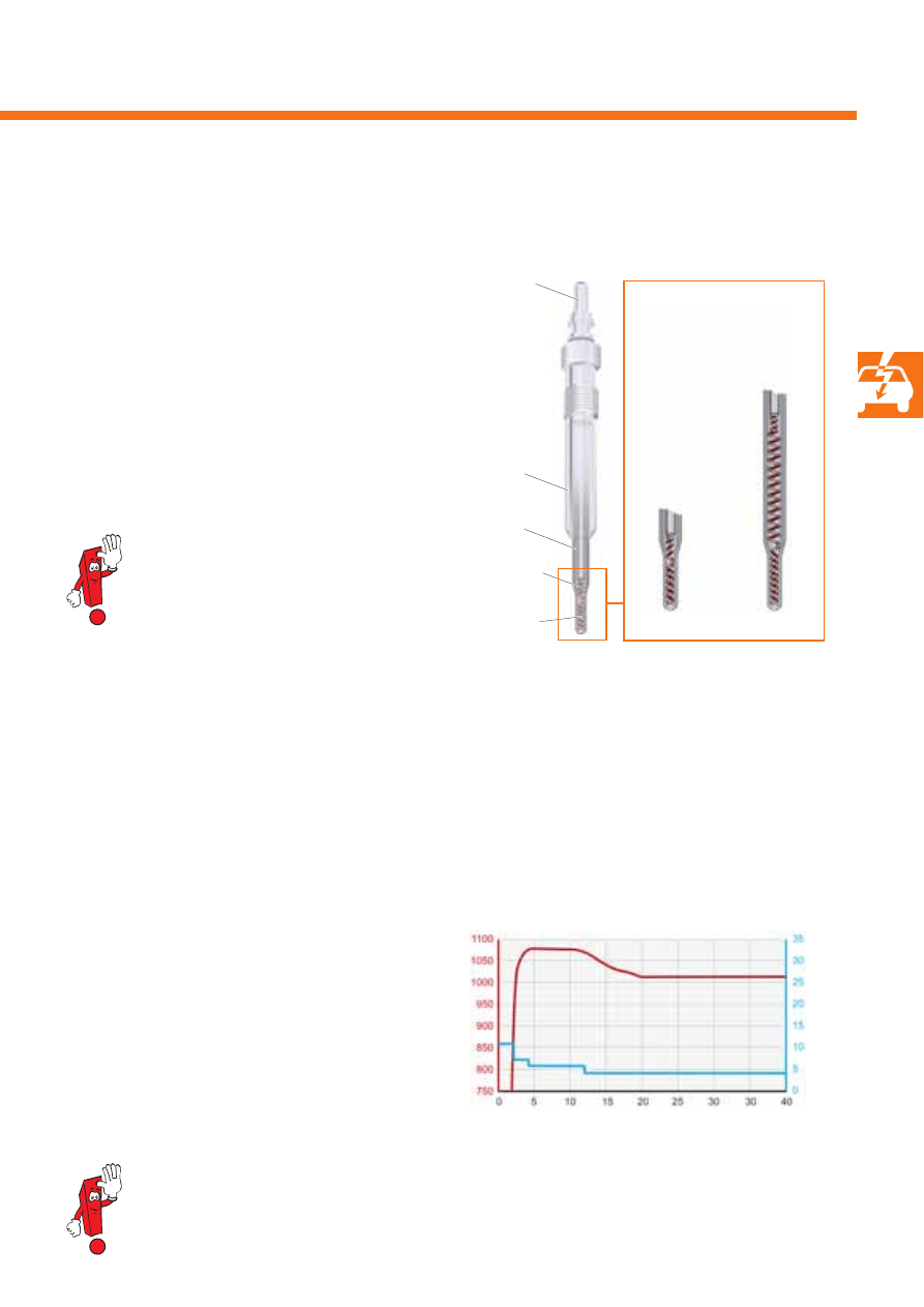
Glow plugs
The glow plugs are made up of the plug body, the
connecting pin and the heating element with heating
and control coil.
In comparison with conventional, self-regulating glow
plugs, the coil combination, comprised of the control
coil and the heating coil, is approximately one-third
shorter. This has enabled the glow period to be
reduced to two seconds.
The glow plugs have a rated voltage of 4.4 V.
Never check the function of the glow
plugs with 12 V, as the glow plugs
otherwise melt!
V
oltage (V)
Temper
atur
e (°C
)
Time (s)
Connecting pin
Heating coil
Plug body
Heating
element
Conventional
glow plug
Glowing
After switching on the ignition, the glow plugs are switched on via the automatic glow period control unit by the
diesel direct injection system control unit J248 at a temperature of less than 20 °C. During the initial glowing phase,
the glow plugs are operated at a voltage of approx. 11 V for a maximum of two seconds. The glow plugs are then
supplied with the voltage required for the relevant operating status by the automatic glow period control unit.
To relieve the onboard supply, glow plug initialisation is phase-offset.
Post-start glowing
Post-start glowing is carried out each time after the
engine has been started, in order to minimise
combustion noise and reduce hydrocarbon emissions.
Glow plug initialisation is corrected by the diesel
direct injection system control unit J248 depending on
load and engine speed.
Post-start glowing is no longer carried out as of a coolant temperature of 35 °C. Post-start glowing is
interrupted after a maximum of three minutes.
Control coil
Glow plug with
shortened
coil
combination
52
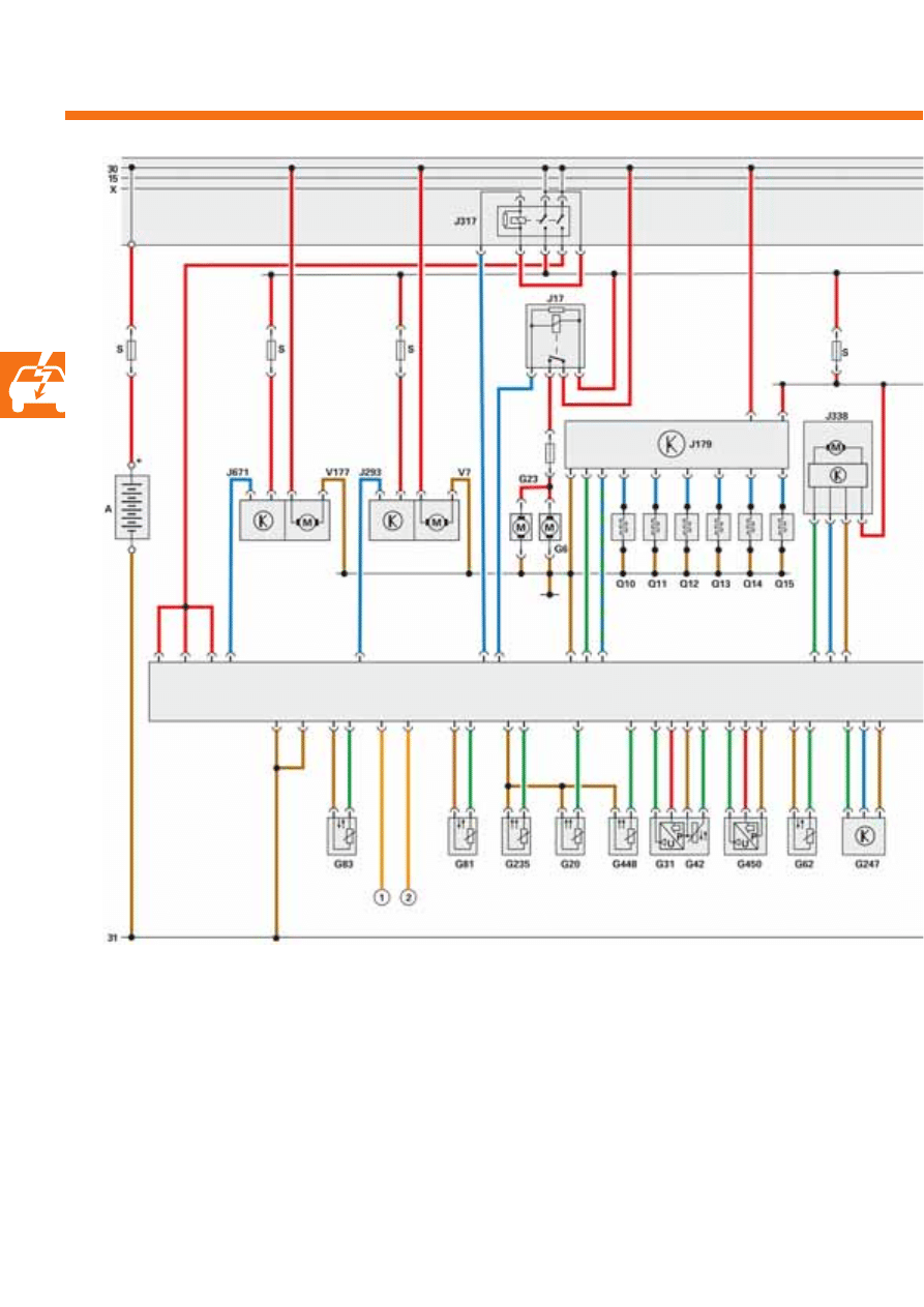
Engine management system
G81
Fuel temperature sender
G83
Radiator outlet coolant temperature sender
G185
Accelerator position sender 2
G235
Exhaust gas temperature sender 1
G247
Fuel pressure sender
G448
Bank 1 exhaust gas temperature sender 2
G450
Exhaust gas pressure sensor 1
J17
Fuel pump relay
J179
Automatic glow period control unit
J248
Diesel direct injection system control unit
J293
Radiator fan control unit
J317
Terminal 30 voltage supply relay
J338
Throttle valve module
J671
Radiator fan control unit 2
J724
Turbocharger 1 control unit
N18
Exhaust gas recirculation valve
A
Battery
F
Brake light switch
F8
Kick-down switch (Phaeton only)*
F36
Clutch pedal switch (Touareg with manual gearbox only)**
F47
Brake pedal switch
G6
Fuel system pressurisation pump
G20
Catalytic converter temperature sensor 1 (Phaeton only)
G23
Fuel pump
G28
Engine speed sender
G31
Charge air pressure sender
G39
Lambda probe
G40
Hall sender
G42
Intake air temperature sender
G62
Coolant temperature sender
G70
Air mass meter
G79
Accelerator position sender
53
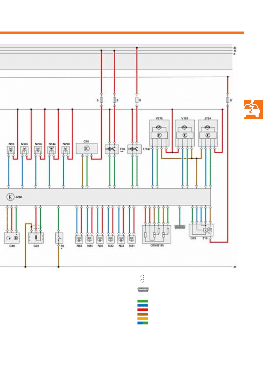
1
2
S351_052
CAN-BUS L
CAN-BUS H
Diagnostic connection
N30
Injector, cylinder 1
N31
Injector, cylinder 2
N32
Injector, cylinder 3
N33
Injector, cylinder 4
N83
Injector, cylinder 5
N84
Injector, cylinder 6
N144
Left electrohydraulic engine mounting solenoid valve (Phaeton)
N276
Fuel pressure regulating valve
N290
Fuel metering valve
N345
Exhaust gas recirculation cooler change-over valve
Q10-15
Glow plugs 1 – 6
S
Fuse
V7
Radiator fan
V157
Intake manifold flap motor
V177
Radiator fan 2
V275
Intake manifold flap 2 motor
Z19
Lambda probe heater
= Input
signal
= Output
signal
= Positive
= Earth
= CAN
BUS
= Bi-directional

54
Test your knowledge
1.
What are the advantages of injectors which are initialised via a piezo actuator versus injectors
controlled by solenoid valves?
a) More injections per working cycle are possible.
b) The injection quantities can be metered more precisely.
c) The fuel is injected into the combustion chamber in more finely atomised form.
d) The injector is able to generate higher fuel pressure.
2.
Which statement on the piezo actuator is correct?
a) A piezo actuator's switching speed corresponds to that of a solenoid valve.
b) The inverse piezo-electric effect is used to control the piezo actuator.
c) The piezo actuator acts like a hydraulic cylinder and serves to transmit force to the switching valve.
3.
Which statement applies to Injector Delivery Calibration (IDC)?
a) Injector delivery calibration is a software function in the diesel direct injection system control unit for
initialising the injectors.
b) If an injector is renewed, it must be matched to the fuel injection system by means of injector delivery
calibration.
c) Injector delivery calibration ensures that all injectors can be manufactured without production tolerances.
4.
What is the task of the fuel metering valve N290?
a) It maintains a fuel pressure of approx. 10 bar in the injectors' fuel return.
b) It regulates the quantity of fuel which flows to the high-pressure pump.
c) It regulates the quantity of fuel which is injected into the combustion chambers.
d) Depending on the fuel temperature, it conducts the fuel returning from the high-pressure pump, the high-
pressure accumulators and the injectors back into the fuel filter or to the fuel tank.

55
Answ
ers
1.
a), b)
2.b)
3.a), b)
4.b)
5.a), c)
6.a)
5.
Which statement on the fuel pressure regulating valve N276 is correct?
a) Engine operation is not possible in the event of fuel pressure regulating valve failure.
b) The engine continues to operate in emergency running mode in the event of fuel pressure regulating valve
failure.
c) The fuel pressure regulating valve is used to adjust the fuel pressure in the high-pressure accumulator.
d) The fuel pressure regulating valve is used to adjust the fuel pressure in the injectors' fuel return.
6.
The pressure retention valve maintains a fuel pressure of approx. 10 bar in the injectors' fuel return.
What is this fuel pressure required for?
a) For the injectors' function.
b) For the high-pressure pump's function.
c) For faster fuel heating.
d) For compensating pressure fluctuations in the high-pressure accumulator.
351
© VOLKSWAGEN AG, Wolfsburg
All rights and rights to make technical alterations reserved.
000.2811.65.20 Technical status 07.2005
Volkswagen AG
Service Training VK-21
Brieffach 1995
38436 Wolfsburg
❀
This paper was manufactured from pulp that was bleached without the use of chlorine.
Wyszukiwarka
Podobne podstrony:
Self Study Programme 365 4 2L V8 with common rail
Self Study Programme 279 2 0L 110kw with petrol direct injection FSI
Self Study Programme 388 4 2L V8 4V FSI engine
Self Study Programme 431 Audi RS 6
Self Study Programme 17 Octavia convenience electronic system
Self Study Programme 189 2 3L petrol engine in the LT 97
Self Study Programme 376 5 2 litre V10 FSI engine
Self Study Programme 396 Lane change assist
Self Study Programme 276 Phaeton automatic proximity control
Self Study Programme 280 Phaeton auxiliary heater top c and top z
Self Study Programme 288 Audi A8 03 distributed functions
Self Study Programme 398 Audi lane assist
Gasoline Fuel Injection System K Jetronic
Fuel Injection Systems Bosch Cis
Mechanics of a Diesel Fuel Injection System
SMeyer CA2067735A1 Water Fuel Injection System
Bmw e12 5 Series L Jetronic Fuel Injection Systems
więcej podobnych podstron