
MSC 84/24/Add.2
ANNEX 14
Page 1
ANNEX 14
RESOLUTION MSC.265(84)
(adopted on 9 May 2008)
AMENDMENTS TO THE REVISED GUIDELINES FOR APPROVAL OF
SPRINKLER SYSTEMS EQUIVALENT TO THAT REFERRED TO
IN SOLAS REGULATION II-2/12 (RESOLUTION A.800(19))
THE MARITIME SAFETY COMMITTEE,
RECALLING Article 28(b) of the Convention on the International Maritime Organization
concerning the functions of the Committee,
NOTING the significance of the performance and reliability of the sprinkler systems
approved under provisions of regulation II-2/12 of the International Convention for the Safety of
Life at Sea (SOLAS), 1974,
DESIROUS of keeping abreast of the advancement of sprinkler technology and further
improving fire protection on board ships,
HAVING CONSIDERED, at its eighty-fourth session, the text of the proposed
amendments to the Revised Guidelines for approval of sprinkler systems equivalent to that
referred to in SOLAS regulation II-2/12 (resolution A.800(19)),
1.
ADOPTS the amendments to the Revised Guidelines for approval of sprinkler systems
equivalent to that referred to in SOLAS regulation II-2/12 (resolution A.800(19)), the text of
which is set out in the annex to the present resolution;
2.
INVITES Governments to apply the amendments when approving equivalent sprinkler
systems on or after 9 May 2008.

MSC 84/24/Add.2
ANNEX 14
Page 2
ANNEX
AMENDMENTS TO REVISED GUIDELINES FOR APPROVAL OF
SPRINKLER SYSTEMS EQUIVALENT TO THAT REFERRED TO IN
SOLAS REGULATION II-2/12 IN THE ANNEX TO RESOLUTION A.800(19)
1
The following new section 1-1 is added after the existing section 1:
“1-1
APPLICATION
1-1.1 The present Guidelines apply to equivalent sprinkler systems installed on or
after 9 May 2008.
1-1.2 Existing type approvals issued to confirm compliance of equivalent sprinkler
systems with the Revised Guidelines, adopted by resolution A.800(19), should remain
valid until 6 years after 9 May 2008.
1-1.3 Existing equivalent sprinkler systems installed before 9 May 2008, based on
resolution A.800(19), should be permitted to remain in service as long as they are
serviceable.”.
3
PRINCIPAL REQUIREMENTS FOR THE SYSTEM
2
The existing paragraph 3.3 is replaced by the following:
“3.3
The sprinkler system should be capable of continuously supplying the water-based
extinguishing medium for a minimum of 30 min. A pressure tank or other means should
be provided to meet the functional requirement stipulated in the FSS Code, chapter 8,
paragraph 2.3.2.1. The design of the system should ensure that full system pressure is
available at the most remote nozzle in each section within 60 s of system activation.”
3
The existing paragraphs 3.8 and 3.9 are replaced by the following:
“3.8
There should be not less than two sources of power for the system. Where the
sources of power for the pump are electrical, these should be a main generator and an
emergency source of power. One supply for the pump should be taken from the main
switchboard, and one from the emergency switchboard by separate feeders reserved
solely for that purpose. The feeders should be so arranged as to avoid galleys, machinery
spaces and other enclosed spaces of high fire risk except in so far as it is necessary to
reach the appropriate switchboards, and should be run to an automatic changeover switch
situated near the sprinkler pump. This switch should permit the supply of power from the
main switchboard so long as a supply is available there from, and be so designed that
upon failure of that supply it will automatically change over to the supply from the
emergency switchboard. The switches on the main switchboard and the emergency
switchboard should be clearly labelled and normally kept closed. No other switch should
be permitted in the feeders concerned. One of the sources of power supply for the system
should be an emergency source. Where one of the sources of power for the pump is an
internal combustion engine, it should, in addition to complying with the provisions of
the FSS Code, chapter 8, paragraph 2.4.3, be so situated that a fire in any protected space

MSC 84/24/Add.2
ANNEX 14
Page 3
will not affect the air supply to the machinery. Pump sets consisting of two diesel
engines each supplying at least 50% of the required water capacity are considered
acceptable if the fuel supply is adequate to operate the pumps at full capacity for a period
of 36 h on passenger ships and 18 h on cargo ships.
3.9
The system should be provided with a redundant means of pumping, including
drivers, or otherwise supplying a water-based extinguishing medium to the sprinkler
system. The capacity of the redundant means should be sufficient to compensate for the
loss of any single supply pump or alternative source.
Failure of any one component in the power and control system should not result in a
reduction of the automatic release capability or reduction of sprinkler pump capacity by
more than 50%. Hydraulic calculations should be conducted to assure that sufficient flow
and pressure are delivered to the hydraulically most remote 140 m
2
in the event of the
failure of any one component.”
4
The existing paragraph 3.13 is replaced by the following:
“3.13 Each section of sprinklers should be capable of being isolated by one stop valve
only. The stop-valve in each section should be readily accessible in a location outside of
the associated section or in cabinets within stairway enclosures. The valve’s location
should be clearly and permanently indicated. Means should be provided to prevent the
operation of the stop-valves by an unauthorized person. Isolation valves used for service,
maintenance or for refilling of antifreeze solutions may be installed in the sprinkler piping
in addition to the section stop valves, if provided with a means for giving a visual and
audible alarm as required by paragraph 3.17. Valves on the pump unit may be accepted
without such alarms if they are locked in the correct position.”
5
The existing paragraph 3.15 is replaced by the following:
“3.15 The sprinkler system water supply components should be outside category A
machinery spaces and should not be situated in any space required to be protected by the
sprinkler system.”
6
The existing paragraph 3.19 is replaced by the following:
“3.19 Installation plans and operating manuals should be supplied to the ship and be
readily available on board. A list or plan should be displayed showing the spaces covered
and the location of the zone in respect of each section. Instructions for testing and
maintenance should also be available on board. The maintenance instructions should
include provisions for a flow test of each section at least annually to check for possible
clogging or deterioration in the discharge piping.”
7
The existing paragraph 3.22 is replaced by the following:
“3.22 Pumps and alternative supply components should be capable of supplying the
required flow rate and pressure for the space with the greatest hydraulic demand. For the
purposes of this calculation, the design area used to calculate the required flow and
pressure should be the deck area of the most hydraulically demanding space, separated
from adjacent spaces by A-class divisions. The design area need not exceed 280 m
2
.
For
application to a small ship with a total protected area of less than 280
m
2
,

MSC 84/24/Add.2
ANNEX 14
Page 4
the Administration may specify the appropriate area for sizing of pumps and alternate
supply components.”
3.23 The nozzle location, type of nozzle, and nozzle characteristics should be within
the tested limits determined by the fire test procedures in appendix 2 to provide fire
control or suppression as referred to in paragraph 3.2.
3.24 For atriums with intermediate level deck openings exceeding 100 m
2
, ceiling
mounted sprinklers are not required.
3.25 The system should be designed in such a way that during a fire occurrence, the
level of protection provided to those spaces unaffected by fire is not reduced.
3.26
A quantity of spare water mist nozzles should be carried for all types and ratings
installed on the ship as follows:
Total number of nozzles
Required number of spares
< 300
6
300 to 1000
12
> 1000
24
The number of spare nozzles of any type need not exceed the total number of nozzles
installed of that type.
3.27 Any parts of the system which may be subjected to freezing temperatures in
service should be suitably protected against freezing.”
APPENDIX 1
COMPONENT MANUFACTURING STANDARDS
FOR WATER MIST NOZZLES
8
In appendix 1, a new paragraph 5.21.4 is added as follows:
“5.21.4 Alternative supply arrangements to the apparatus shown in figure 3 may be used
where damage to the pump is possible. Restrictions to piping defined by note 2 of table 5
should apply to such systems.”
APPENDIX 2
FIRE TEST PROCEDURES FOR EQUIVALENT SPRINKLER SYSTEMS
IN ACCOMMODATION, PUBLIC SPACE AND SERVICE AREAS
ON PASSENGER SHIPS
9
The existing title and the text of appendix 2 is replaced by the following:

MSC 84/24/Add.2
ANNEX 14
Page 5
“APPENDIX 2
FIRE TEST PROCEDURES FOR WATER MIST SYSTEMS
IN ACCOMMODATION, PUBLIC SPACES AND SERVICE AREAS
ON PASSENGER SHIPS
1 S
COPE
1.1
These test procedures describe a fire test method for evaluating the effectiveness
of water mist systems equivalent to systems covered by chapter 8 of the FSS Code in
accommodation and service areas on board ships. It should be noted that the test method
is limited to the systems’ effectiveness against fire and is not intended for testing of the
quality and design parameters of the individual components of the system.
1.2
In order to fulfil the requirements of paragraph 3.5 of the Guidelines, the system
should be capable of fire control or suppression in a wide variety of fire loading, fuel
arrangement, room geometry and ventilation conditions.
1.3 Products
employing
materials
or having forms of construction differing from the
requirements contained herein may be examined and tested in accordance with the intent
of the requirements and, if found to be substantially equivalent, may be judged to comply
with this document.
1.4
Products complying with the text of this document will not necessarily be judged
to comply, if, when examined and tested, they are found to have other features which
impair the level of safety contemplated by this document.
2 H
AZARD AND OCCUPANCY CLASSIFICATION
For the purposes of identifying the different fire risk classifications, table 1 is given,
which correlates the fire tests with the classification of occupancy defined in
SOLAS regulations II-2/9.2.2.3 and II-2/9.2.2.4:
Table 1 – Correlation between fire tests with the classification of occupancy defined
in SOLAS regulations II-2/9.2.2.3 and 9.2.2.4
Corresponding fire test
Occupancy classification
Section 5
cabin
Section 5
corridor
Section 6
public
spaces
Section 8
storage
(1)
Control stations
X
(2) Stairways
X
1
(3) Corridors
X
1
(6) Accommodation
spaces
of
minor
fire risk
X
2
X
3
(7) Accommodation
spaces
of
moderate fire risk
X
2
X
3 4
(8) Accommodation
spaces
of
greater fire risk
X
3 4

MSC 84/24/Add.2
ANNEX 14
Page 6
Corresponding fire test
Occupancy classification
Section 5
cabin
Section 5
corridor
Section 6
public
spaces
Section 8
storage
(9)
Sanitary and similar spaces
X
2
X
3
(11) Refrigerated chambers
X
(12) Main galleys and annexes
X
(13) Store rooms, workshops,
pantries, etc.
X
(14) Other spaces in which flammable
liquids are stowed
X
Notes:
1
For corridors and stairways wider than 1.5 m, use section 6 public space fire test instead of the
corridor fire test.
2
For spaces up to the area of the cabin applied in tests of section 5.
3
For spaces over the area of the cabin applied in tests of section 5.
4
Refer to annex, item 3.24.
3 D
EFINITIONS
3.1
Fire suppression: sharply reducing the heat release rate of a fire and preventing its
re-growth by means of a direct and sufficient application of water through the fire plume
to the burning fuel surface.
3.2
Fire control: limiting the size of a fire by distribution of water so as to decrease
the heat release rate and pre-wet adjacent combustibles, while controlling ceiling gas
temperatures to avoid structural damage.
3.3
Fire source: fire source is defined as the combustible material in which the fire is
set and the combustible material covering walls and ceiling.
3.4
Igniter: the device used to ignite the fire source.
4 G
ENERAL REQUIREMENTS
4.1 Nozzle
positioning
The fire test procedures are intended for pressurized wet-pipe systems with individually
activated (automatic) nozzles.
Water without any fire-extinguishing additives should be used, unless the additives have
been approved for fire protection service by an independent authority. The approval of
the additives should consider possible adverse health effects to exposed personnel,
including inhalation toxicity.
These test procedures are applicable to either overhead nozzles installed on the ceiling, or
sidewall nozzles installed on bulkheads below the ceiling. Separate approval tests should
be conducted for each nozzle type.

MSC 84/24/Add.2
ANNEX 14
Page 7
The testing organization should be responsible for assuring that the nozzles for each fire
test are installed in accordance with the manufacturer’s design and installation
instructions. The tests should be performed at the maximum specified spacings,
installation height and distances below the ceiling. In addition, if the testing organization
finds it necessary, selected fire tests should also be conducted at minimum specified
spacings, installation height and distances below the ceiling. Where two types of nozzles
are installed in the same area, an overlap of the different nozzle spray patterns should be
provided equal to at least one half of the maximum approved nozzle spacing.
4.2
Water pressure and flow rates
The testing organization should be responsible for assuring that all fire tests are
conducted at the operating pressure and flow rates specified by the manufacturer.
For all tests, the system should either be:
.1
pressurized to the minimum operating pressure specified by the
manufacturer. Upon activation of the first nozzle, the flowing water pressure
should be maintained at the minimum system operating pressure; or
.2
pressurized to the minimum stand-by pressure specified by the
manufacturer. Upon activation of the first nozzle, the flowing water
pressure should be gradually increased to the minimum system operating
pressure, specified by the manufacturer. The delay time until the
minimum system operating pressure is reached should be at least 15 s.
The delay time recorded during the tests should be documented and
included in the approval of the system.
4.3 Temperature
measurements
Temperatures should be measured as described in detail under each chapter.
Chromelalumel thermocouple wires not exceeding 0.5 mm in diameter welded together
should be used. The temperatures should be measured continuously, at least every 2 s,
throughout the tests.
4.4
Fire test hall and environmental conditions
The fire tests are to be conducted inside a well-ventilated fire test hall, in order to
minimize enclosure effects affecting the outcome of the testing. The enclosure effects
include accumulation of heat, smoke and water droplets within the test area.
The fire test hall should have an ambient temperature of 20 ± 5°C at the start of each test.
Standing water should not be permitted on the floor of the test hall at the start of each
test. The suspended ceiling should be dry at the start of each test.
Details of the fire test hall geometry, the ventilation conditions as well as of the
environmental conditions with respect to the above should be given in the fire test report.

MSC 84/24/Add.2
ANNEX 14
Page 8
4.5 Tolerances
Unless otherwise stated, the following tolerances should apply:
.1
length
± 2% of value;
.2
volume
± 5% of value;
.3
pressure
± 3% of value; and
.4
temperature ± 5% of value.
These tolerances are in accordance with ISO Standard 6182-1:1994.
4.6 Observations
The following observations should be made during and after each test:
.1
time of ignition;
.2
activation time of each nozzle;
.3
time when water flow is shut off;
.4
damage to the fire source;
.5 temperature
recordings;
.6
system flow rate and pressure; and
.7
total number of operating nozzles.
4.7 Fire
sources
If the requirements for fire sources specified in the following sections of this test method
cannot be fulfilled, it is the responsibility of the test laboratory to show that alternative
materials used have burning characteristics similar to those of specified materials.
4.8
Product and documentation requirements
The fire test report should identify the critical parameters to be incorporated into the
design, installation and operating instruction manual. The instruction manual should
reference the limitations of each device and should include at least the following items:
.1
description and operating details of each device and all accessory
equipment, including identification of extinguishing system components or
accessory equipment by part or model number;
.2
nozzle design recommendation and limitations for each fire type;

MSC 84/24/Add.2
ANNEX 14
Page 9
.3
type and pressure rating of pipe, tubing and fittings to be used;
.4
equivalent length values of all fittings and all system components through
which water flows;
.5
discharge nozzle limitations, including maximum dimensional and area
coverage, minimum and maximum installation height limitations, and
nozzle permitted location in the protected volume;
.6
range of filling capacities for each size storage container;
.7
details for the proper installation of each device, including all component
equipment;
.8
reference to the specific types of detection and control panels
(if applicable) to be connected to the equipment;
.9
operating pressure ranges of the system;
.10
method of sizing pipe or tubing;
.11
recommended orientation of tee fittings and the splitting of flows through
tees; and
.12
maximum difference in operating (flowing) pressure between the
hydraulically closest and most remote nozzle.
5 C
ABIN AND CORRIDOR TESTS
5.1 Test
arrangement
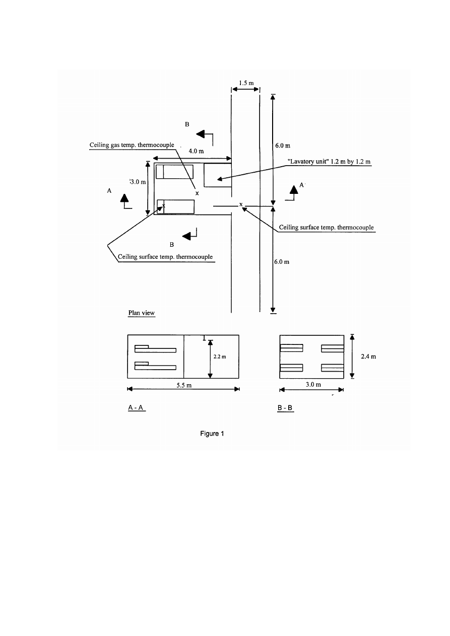
5.1.1 The fire tests should be conducted in a 3 m x 4 m, 2.5 m high cabin connected to
the centre of a 1.5 m x 12 m long corridor, 2.5 m high with both ends open. The cabin
area may be increased up to the maximum size to be protected with one nozzle.
The disabled nozzle test should be conducted in a 3 m x 4 m cabin.
5.1.2 The cabin should be fitted with one doorway opening, 0.8 m wide and 2.2 m high,
which provides for a 0.3 m lintel above the opening.
5.1.3 The walls of the cabin should be constructed from an inner layer of
nominally 12 mm thick non-combustible wall board with a nominally 45 mm thick
mineral wool liner. The walls and ceiling of the corridor and ceiling of the cabin should
be constructed of nominally 12 mm thick non-combustible wall boards. The cabin may
be provided with a window, having a maximum area of 1 m
2
, in the wall opposite the
corridor for observation purposes during the fire tests.
5.1.4 The cabin and corridor ceiling should be covered with cellulosic acoustical panels.
The acoustical panels should be nominally 12 mm to 15 mm thick and should not ignite
when tested in accordance with part 3 of the FTP Code.

MSC 84/24/Add.2
ANNEX 14
Page 10
5.1.5 Plywood panels should be placed on the cabin and corridor walls. The panels
should be 3 to 4 mm thick. The ignition time of the panel should be not more than 35 s
and the flame spread time at 350 mm position should not be more than 100 s as measured
in accordance with IMO resolution A.653(16).
5.2 Instrumentation
During each fire test, the following temperatures should be measured using
thermocouples of diameter not exceeding 0.5 mm:
.1
the ceiling surface temperature above the ignition source in the cabin
should be measured with a thermocouple embedded in the ceiling material
from above such that the thermocouple bead is flush with the ceiling;
.2
the ceiling gas temperature should be measured with a
thermocouple 75 ± 1 mm below the ceiling in the centre of the cabin;
.3
the ceiling surface temperature in the centre of the corridor, directly
opposite the cabin doorway, should be measured with a thermocouple
embedded in the ceiling material such that the thermocouple bead is flush
with the ceiling (figure 1); and
.4
the ceiling surface temperature directly above the corridor test fire source
(if used) described in paragraph 5.4.2 should be measured with a
thermocouple embedded in the ceiling material such that the thermocouple
bead is flush with the ceiling surface.
Thermocouples intended for measuring ceiling surface temperatures should be imbedded
in a shallow groove filled with thermally conductive cement such that the thermocouple
bead is flush with the ceiling surface. The distance from the hole where the thermocouple
wire penetrates the ceiling tile to the bead should be at least 25 mm.
5.3 Nozzle
positioning
The nozzles should be installed to protect the cabin and corridor in accordance with the
manufacturer’s design and installation instructions subject to the following:
.1
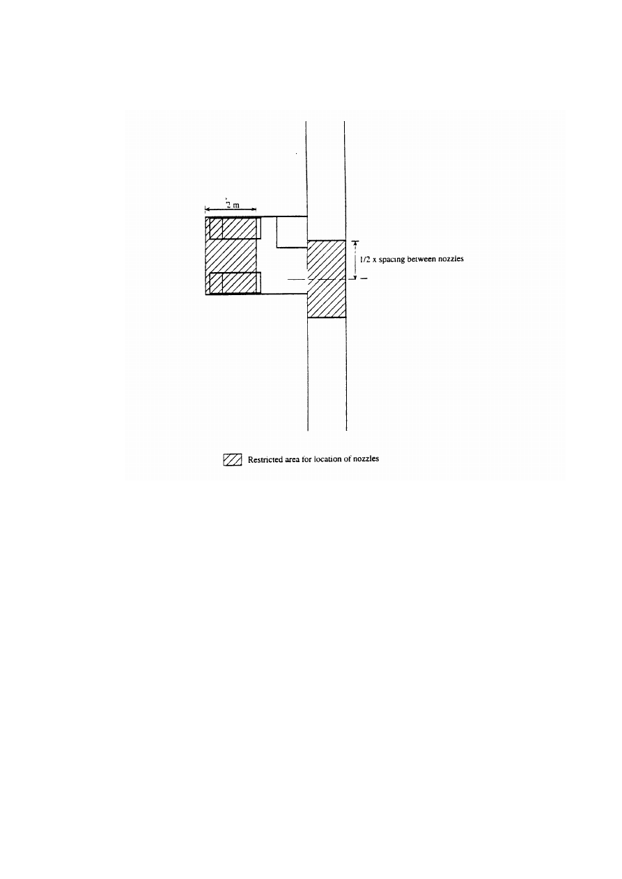
if only one ceiling nozzle is installed in the cabin, it may not be placed in
the shaded area in figure 2;
.2
if two or more ceiling nozzles are installed in the cabin the nominal water
flux density should be homogeneously distributed throughout the cabin;
.3
corridor nozzles should not be placed closer to the centreline of the cabin
doorway than one half the maximum spacing recommended by the
manufacturer. An exception is systems where nozzles are required to be
placed outside each doorway; and
.4
cabin mounted sidewall nozzles should be installed on the centreline of the
front wall of the cabin adjacent to the doorway, aimed towards the rear of
the cabin.

MSC 84/24/Add.2
ANNEX 14
Page 11
5.4 Fire
sources
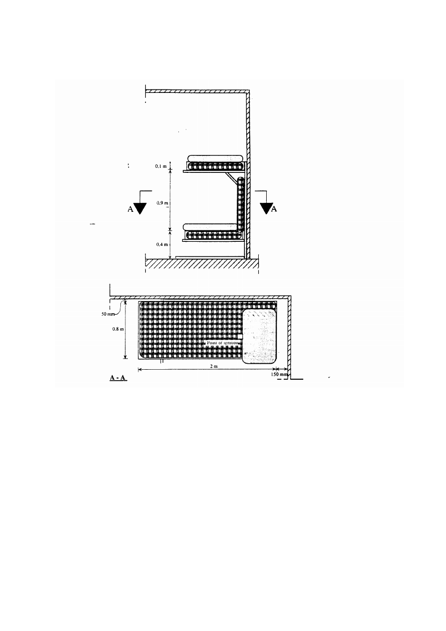
5.4.1 Cabin test fire source
Two pullman-type bunk beds having an upper and lower berth should be installed along
the opposite side walls of the cabin (figure 1). The bunk beds should be made of
nominally 1.5 mm thick steel and should have an outer dimension of approximately 2.0 m
by 0.8 m. The bunk beds should have a 0.1 m high rim facing the long side wall of the
cabin. No other rims are allowed in order to prevent accumulation of water onto the beds.
Each bunk bed should be fitted with 2 m by 0.8 m by 0.1 m polyether mattresses having a
cotton fabric cover. Pillows measuring 0.5 m by 0.8 m by 0.1 m should be cut from the
mattresses. The cut edge should be positioned towards the doorway. A third mattress
should form a backrest for the lower bunk bed. The backrest should be attached in an
upright position in a way that prevents it from falling over (figure 3).
The mattresses should be made of non-fire retardant polyether and they should have a
density of approximately 33 kg/m
3
. The cotton fabric should not be fire retardant treated
and it should have an area weight of 140 g/m
2
to 180 g/m
2
. When tested according to
ISO Standard 5660-1:2002 (ASTM E-1354), the polyether foam should give results as
given in the table below. The frame of the bunk beds should be of steel
nominally 2 mm thick.
ISO STANDARD 5660: Cone calorimeter test
Test conditions: Irradiance 35 kW/m
2
. Horizontal position.
Sample thickness 50 mm. No frame retainer should be used.
Test
results
Foam
Time to ignition (s)
2-6
3 min average HRR, q180 (kW/m
2
)
270 ± 50
Minimum heat of combustion (MJ/kg)
25
Total heat release (MJ/m
2
)
50
±
12
5.4.2 Corridor test fire source
The corridor fire tests should be conducted using eight piled polyether mattress pieces
measuring 0.4 m x 0.4 m x 0.1 m, as specified in paragraph 5.4.1, without fabric covers.
The pile should be placed on a stand, 0.25 m high, and in a steel test basket to prevent the
pile from falling over (figure 4).
5.5 Test
method
The following series of fire tests should be performed with automatic activation of the
nozzle(s) installed in the cabin and/or corridor as indicated. Each fire should be ignited
using an igniter made of some porous material, e.g., pieces of insulating fibreboard.
The igniter may be either square or cylindrical, 60 mm square or 75 mm in diameter.
The length should be 75 mm. Prior to the test the igniter should be soaked in 120 ml of
heptane and positioned as indicated for each cabin fire test. For the corridor fire tests, the
igniter should be located in the centre at the base of the pile of the mattress pieces, and on
one side of the test stand at the base of the pile of mattress pieces:

MSC 84/24/Add.2
ANNEX 14
Page 12
.1
lower bunk bed test. Fire arranged in one lower bunk bed and ignited with
the igniter located at the front (towards door) centreline of the pillow;
.2
upper bunk bed test. Fire arranged in one upper bunk bed with the igniter
located at the front (towards door) centreline of the pillow;
.3
arsonist test. Fire arranged by spreading 1 litre of white spirits evenly over
one lower bunk bed and backrest 30 s prior to ignition. The igniter should
be located in the lower bunk bed at the front (towards doorway opening)
centreline of the pillow;
.4
disabled nozzle test. The nozzle(s) in the cabin should be disabled. Fire
arranged in one lower bunk bed and ignited with the igniter located at the
front (towards door) centreline of the pillow. If nozzle(s) in the cabin are
linked with nozzle(s) in the corridor such that a malfunction would affect
them all, all cabin and corridor nozzles linked should be disabled;
.5
corridor test. Fire source located against the wall of the corridor under one
nozzle; and
.6
corridor test. Fire source located against the wall of the corridor between
two nozzles.
The fire tests should be conducted for 10 min after the activation of the first nozzle, and
any remaining fire should be extinguished manually.
The door opening to the cabin is intended to be open during the tests according to
paragraphs 5.5.1 through 5.5.4 and closed during the tests according to paragraphs 5.5.5
and 5.5.6.
5.6 Acceptance
criteria
Based on the measurements, a maximum 30 s average value should be calculated for each
measuring point which forms the temperature acceptance criteria.

MSC 84/24/Add.2
ANNEX 14
Page 13
Acceptance criteria for the cabin and corridor tests
Maximum
acceptable
damage on
mattresses
(%)
Maximum
30 s
average
ceiling
surface
temperature
in the
cabin
(º C)
Maximum
30 s
average
ceiling gas
temperature
in the cabin
(º C)
Maximum
30 s
average
ceiling
surface
temperature
in the
corridor
(º C)
Lower
bunk
Upper
bunk
Other criteria
Lower
bunk
bed
40 10
Upper
bunk
bed
360 320 120
N.A. 40
No nozzles
in corridor
allowed to
operate
3
Cabin
tests
Arsonist
N.A. N.A. 120
N.A.
N.A. N.A.
Corridor
tests
N.A. N.A.
120
1
N.A.
Only two
Independent and
adjacent
nozzles in
corridor
allowed to
operate
4
Disabled
nozzle
N.A. N.A.
400
2
N.A.
N.A.
Notes:
1
In each test, the temperature should be measured above the fire source.
2
The fire is not allowed to propagate along the corridor beyond the nozzles closest to the door
opening.
3
Not applicable, if cabin nozzle(s) are linked to corridor nozzle(s).
4
Not applicable, if corridor nozzle(s) are linked together.
N.A. means not applicable
5.7 Damage
calculations
After the test, the fire sources should be examined visually to determine compliance with
the required maximum damage. The damages should be estimated using the following
formula:
.1
damage to lower bunk bed = (damage to horizontal mattress (%) + 0.25 x
damage to pillow (%) + damage to backrest (%))/2.25;
.2
damage to upper bunk bed = (damage to horizontal mattress (%) + 0.25 x
damage to pillow (%))/1.25; and

MSC 84/24/Add.2
ANNEX 14
Page 14
.3
if it is not clearly obvious by visual examination whether the criteria are
fulfilled or not, the test should be repeated.
6 P
UBLIC SPACE FIRE TESTS
6.1 Test
arrangements
The fire tests should be conducted inside a well-ventilated fire test hall as described in
item 4.4 under a suspended rectangular ceiling of at least 80 m
2
in area with no
dimensions less than 8 m. There should be at least 1 m space between the perimeters of
the ceiling and any wall of the test hall. The ceiling height should be set at 2.5 m
and 5 m, respectively.
The ceiling should be horizontal and smooth to allow an unobstructed horizontal flow of
gases across the whole ceiling. No lintel is allowed around the perimeter of the ceiling
and no opening is permitted in the ceiling. In order to be considered as smooth, the
surface structure of the suspended ceiling should not have obstructions deeper
than 15 mm.
The volume above the suspended ceiling, should be large enough, or be fitted with a
natural or mechanical ventilation system, to vent the combustion gases away from the fire
test area.
Details of the ceiling structure and its location in the fire test hall should be given in the
fire test report.
Two different tests should be conducted as per paragraphs 6.1.1 and 6.1.2.
6.1.1 Open public space test
The fire source should be positioned under the centre of the open ceiling so that there is
an unobstructed flow of gases across the ceiling. The ceiling should be constructed from a
non-combustible material. At least 1 m
2
of the ceiling just above ignition should be covered
with acoustical panels. The acoustical panels should be nominally 12 mm to 15 mm
thick, and should not ignite when tested in accordance with part 3 of the FTP Code.
6.1.2 Corner public space test
The test should be conducted in a corner constructed by two at least 3.6 m wide,
nominally 12 mm thick, non-combustible wall boards. Plywood panels should be placed
on the walls. The panels should be 3 to 4 mm thick. The ignition time of the panel
should not be more than 35 s and the flame spread time at 350 mm position should not be
more than 100 s measured in accordance with part 3 of the FTP Code. The ceiling should
be covered, 3.6 m out from the corner, with cellulosic acoustical panels. The acoustical
panels should be nominally 12 mm to 15 mm thick, and should not ignite when tested in
accordance with part 3 of the FTP Code.

MSC 84/24/Add.2
ANNEX 14
Page 15
6.1.3 Verification of ventilation conditions
The ventilation rate of the test hall should be verified at the test hall configuration and
ventilation conditions to be applied in the fire tests. The verification test should be
conducted using a circular 2 m
2
tray filled with at least 50 mm of light diesel oil on a
water-base. Freeboard is to be 150 ± 10 mm. The tray should be centrally located under
the suspended open ceiling at the 2.5 m height The ventilation rate should be high enough
to prevent the oxygen concentration measured at radius of 3 m from the centre point of
the fire source, 1.25 m (mid-height) above the floor, to decrease below 20% volume
during a 10 min free burning test.
The fire test report should include details of the ventilation test, if conducted as a part of
the test series, or alternatively, reference should be provided to a ventilation test that was
performed at the same configuration and ventilation conditions.
6.2 Instrumentation
During each fire test, the following temperatures should be measured using
thermocouples with diameter not exceeding 0.5 mm.
6.2.1 Open public space test:
.1
the ceiling surface temperature above the ignition source should be
measured using a thermocouple embedded in the ceiling material such that
the thermocouple bead is flush with the ceiling surface; and
.2
the ceiling gas temperature should be measured 75 ± 1 mm below the
ceiling, at four different positions, at a horizontal radius of 1.8 m from the
point of ignition. The thermocouples should be oriented 90º relative to
each other and positioned such as to minimize the risk for direct wetting
by the water sprays from the nozzles.
6.2.2 Corner public space test:
.1
the ceiling surface temperature above the ignition source should be
measured using a thermocouple embedded in the ceiling material such that
the thermocouple bead is flush with the ceiling surface; and
.2
the ceiling gas temperature should be measured using a thermocouple
located 75 ± 1 mm below the ceiling within 0.2 m horizontally from the
closest nozzle to the corner.
Thermocouples intended for measuring ceiling surface temperatures should be imbedded
in a shallow groove filled with thermally conductive cement such that the thermocouple
bead is flush with the ceiling surface. The distance from the hole where the thermocouple
wire penetrates the ceiling tile to the bead should be at least 25 mm.

MSC 84/24/Add.2
ANNEX 14
Page 16
6.3 Nozzle
positioning
6.3.1 Open and corner public space tests
For nozzles with frame arms, tests should be conducted with the frame arms positioned
both perpendicular and parallel with the edges of the ceiling or corner walls. For nozzles
without framed arms, the nozzles should be oriented so that the lightest discharge density
will be directed towards the fire area.
6.3.2 Open public space tests
When sofas are positioned between two nozzles, the longitudinal centreline gap between
sofas no.1 and no.2 should be oriented at a 90° angle to the line between the nozzles.
6.4 Fire
sources
6.4.1 Open public space
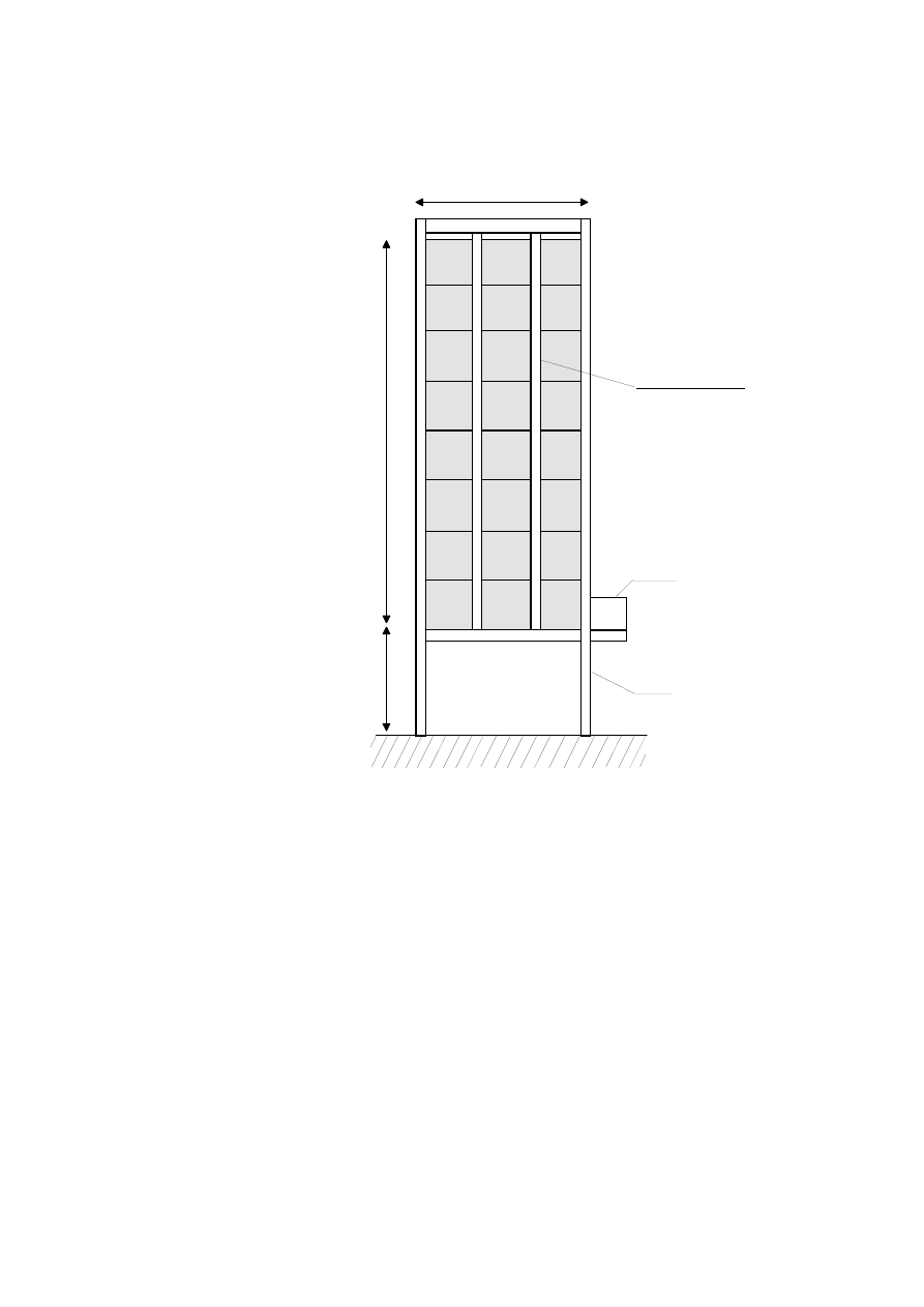
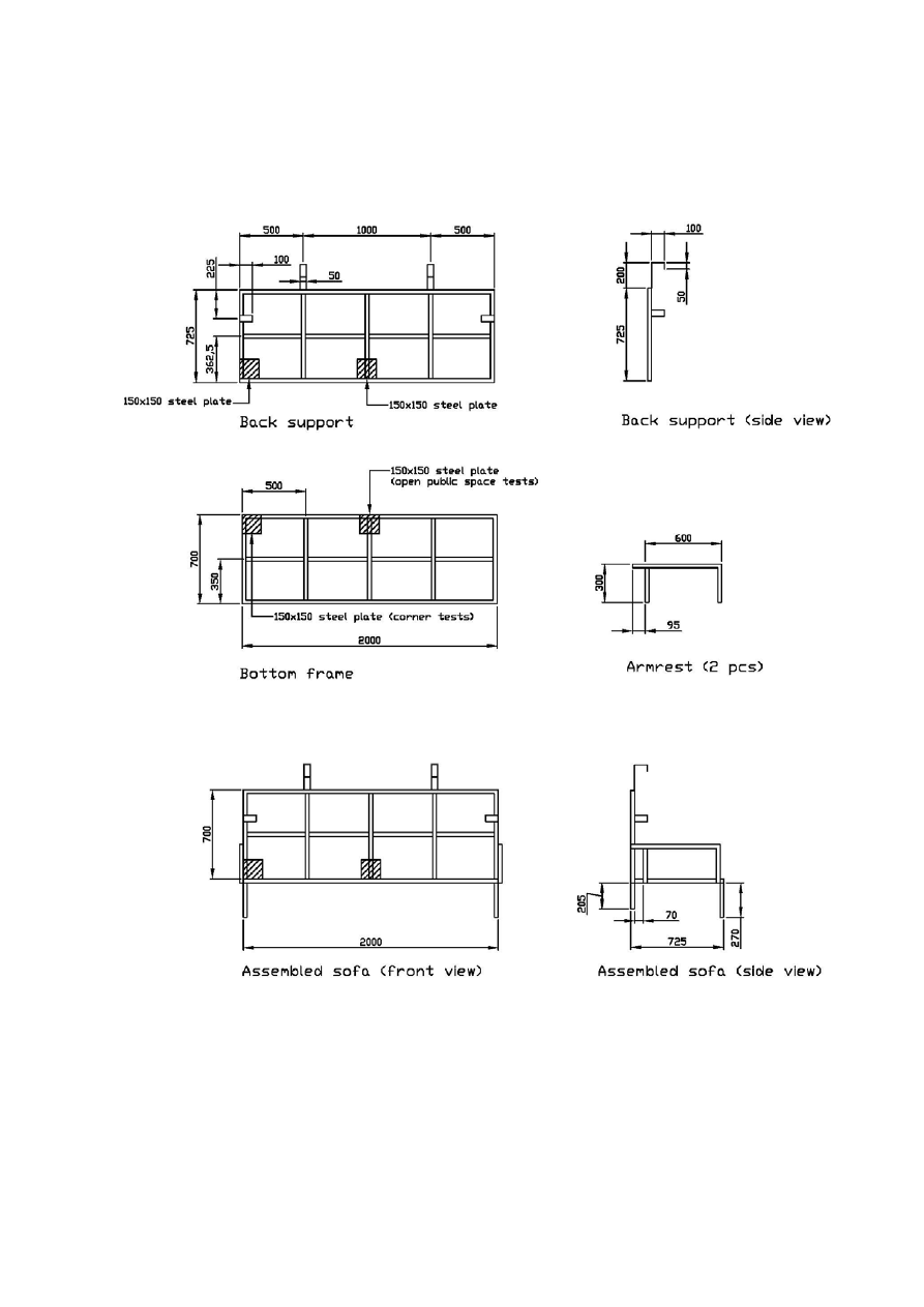
The fire source should consist of four sofas made of mattresses as specified in section 5.4.1
installed in steel frame sofas. The steel frames for the sofas should consist of rectangular
bottom and backrest frames constructed of 25 ± 2 mm square iron of normally 2 mm
thickness. The dimensions of the bottom frame should be 2,000 mm x 700 mm and the
dimensions of the backrest frame should be 2,000 mm x 725 mm. The seat and backrest
mattresses should be supported on each frame by three vertical and one horizontal steel
bars, constructed from similar steel stock. The vertical steel bars should be spaced
every 500 mm and welded to the inner long sides of the frame. The horizontal steel bar
should be welded to the inner short sides of the frame. Both steel frames should be fitted
with a 150 mm by 150 mm steel plate, nominally 2 mm thick. The steel plate should be
positioned directly under and behind the intended position of the igniter, in order to
prevent it from falling to the floor under a test. Each sofa should have a rectangular
armrest on each end. The armrest should be constructed of similar steel stock and should
be 600 mm in length and 300 mm in height. The front section of the armrest should be
attached to the bottom frame 70 mm from the backrest frame. The assembled frames
should be supported by four legs constructed of similar steel stock. The two rear legs
should be 205 mm in height and the front legs should be 270 mm in height. When
installed, the mattress forming the seat should be installed first, with its long side edge
close up against the backrest frame. The mattress forming the backrest should be
installed thereafter. This mattress should be kept in upright position by four hooks, two
on the short sides and two on the long sides of the backrest frame (see figure 5).
The
hooks should be constructed from nominally 50
mm flat iron bars, of
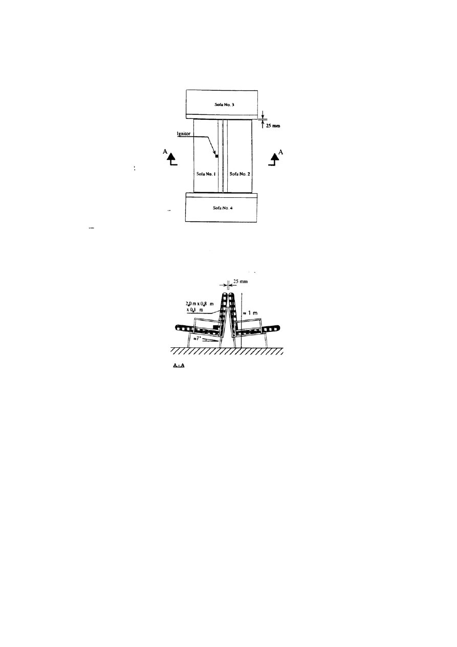
nominally 2 mm thickness. The sofas should be positioned as shown in figure 6, with the
top of the backrests spaced 25 mm apart.
One of the middle sofas should be ignited, centrically and at the bottom of the backrest,
with an igniter as described in section 5.5.
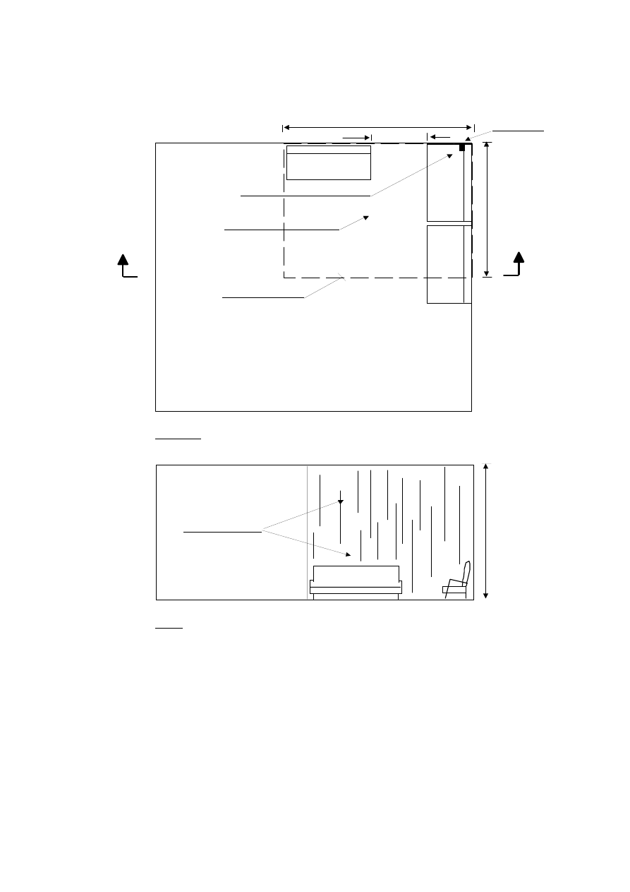
6.4.2 Corner public space test
The fire source should consist of a sofa, as specified in 6.4.1, placed with the
backrest 25 mm from the right-hand wall and close up to the left-hand wall. A target sofa
should be placed along the right-hand wall with the seat cushion 0.1 m from the first sofa
and another target sofa should be placed 0.5 m from it on the left hand side. The sofa

MSC 84/24/Add.2
ANNEX 14
Page 17
should be ignited using an igniter, as described in 5.5, that should be placed at the far left
of the corner sofa, at the base of the backrest, near the left-hand wall (figure 7).
6.5 Test
method
The fire tests should be conducted for 10 min after the activation of the first nozzle, and
any remaining fire should be extinguished manually.
6.5.1 Open public space tests
Fire tests should be conducted with the ignition centred under one, between two and
below four nozzles. An additional test should be conducted with the ignition centred
under a disabled nozzle.
6.5.2 Corner public space test
The fire tests should be conducted with at least four nozzles arranged in a 2 x 2 matrix.
6.6 Acceptance
criteria
Based on the measurements, a maximum 30 s average value should be calculated for each
measuring point which forms the temperature acceptance criteria.
6.6.1 Acceptance criteria for the public space tests
Maximum 30 s
average ceiling
surface temperature
(ºC)
Maximum 30 s
average ceiling
gas temperature
(ºC)
Maximum acceptable
Damage on mattresses
(%)
normal
360 220
2
50/35
1
Open
space
disabled
nozzle
N.A. N.A. 70
Corner
360
220
50/35
1
(ignition sofa)
No charring of target
sofas
Notes:
1
50% is the upper limit for any single test. 35% is the upper limit for the average of the public
space tests required in 6 at each ceiling height (excluding the disabled sprinkler test).
2
The gas temperature should be measured at four different positions and the evaluation of the
results is based on the highest reading.
N.A. means not applicable.
7 S
TORAGE AREA FIRE TESTS
7.1 Test
arrangements
The fire tests should be conducted inside a well-ventilated fire test hall as described in
paragraph 4.4 under a suspended ceiling as described in paragraph 6.1 installed
at 2.5 m height.

MSC 84/24/Add.2
ANNEX 14
Page 18
7.2 Instrumentation
No temperature measurements are required.
7.3 Nozzle
positioning
As per paragraph 6.3.
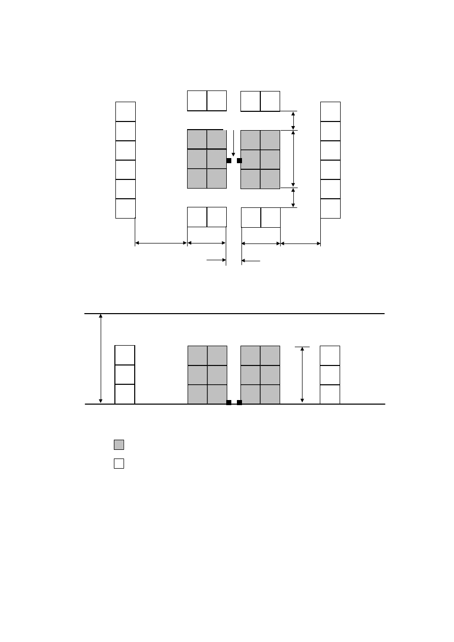
7.4 Fire
source
The fire source should consist of two central, 1.5 m high, solid piled stacks of cardboard
boxes packed with polystyrene unexpanded plastic cups upside down with a 0.3 m flue
space. Each stack should be approximately 1.6 m long and 1.1 m to 1.2 m wide.
A suitable plastic commodity is the FMRC standard plastic commodity. Similar
commodities might be used if they are designed in a similar way and are proven to have
the same burning characteristics and suppressability. In each test, new dry commodities
should be used.
The fire source should be surrounded by six 1.5 m high solid piled stacks of empty
cardboard boxes forming a target array to determine if the fire will jump the aisle.
The boxes should be attached to each other, for example by staples, to prevent them from
falling over (figure 8).
7.5 Test
method
Fire tests should be conducted with the ignition centred under one, between two and
below four nozzles. Each fire should be ignited using two igniters as described in 5.5.
The igniters should be placed on the floor, each against the base of one of the two central
stacks and ignited simultaneously. The fire tests should be conducted for 10 min after the
activation of the first nozzle, and any remaining fire should be extinguished manually.
When positioned between two nozzles, the gap between the two centric stacks of
commodities should be positioned at 90° to the line between the nozzles.
7.6 Acceptance
criteria
.1
no ignition or charring of the target cartons is allowed; and
.2
no more than 50% of the cartons filled with plastic cups should be
consumed.”
MSC 84/24/Add.2
ANNEX 14
Page 19
MSC 84/24/Add.2
ANNEX 14
Page 20
Figure 2
MSC 84/24/Add.2
ANNEX 14
Page 21
Figure 3
MSC 84/24/Add.2
ANNEX 14
Page 22
Figure 4
Stand
Igniter
8 piled mattresses
0.4 m x 0.4 m
0.8 m
0.25 m
0.4 m
MSC 84/24/Add.2
ANNEX 14
Page 23
Figure 5
MSC 84/24/Add.2
ANNEX 14
Page 24
Figure 6
MSC 84/24/Add.2
ANNEX 14
Page 25
Figure 7
Plywood panelling
Left hand,
target sofa
Right hand,
target sofa
x
3.6 m
0.5 m
3.6 m
Ceiling surface temp. thermocouple
Ceiling gas temp. thermocouple
Acoustical ceiling tiles
x
Ignition point
Plan view
A - A
Figure 8
2.5/5.0 m
A
A
MSC 84/24/Add.2
ANNEX 14
Page 26
Figure 8
***
2.5 m
1.5 m
1.2 m
1.1 m
1.1 m
1.2 m
0.6 m
1.6 m
0.6 m
Igniters
0.3 m
Plan view
Front view
Cardboard cartons packed with polystyreneplastic cups
Empty boxes as target arrays
Figure 9
Wyszukiwarka
Podobne podstrony:
Guidelines For Decontamination of Equipment for Gastrointestinal Endoscopy
The Gospel of St John in Relation to the Other Gospels esp that of St Luke A Course of Fourteen Lec
A User Guide To The Gfcf Diet For Autism, Asperger Syndrome And Adhd Autyzm
GUIDELINES FOR THE APPROVAL OF FIXED WATER BASED LOCAL APPLICATION
Kinesio taping compared to physical therapy modalities for the treatment of shoulder impingement syn
APA practice guideline for the treatment of patients with Borderline Personality Disorder
Guidelines for the Management of Aneurysmal Subarachnoid Hemorrhage
The identity of the Word according to John [revised 2007]
ESTRO BOOKLET 5 Practical guidelines for the impletation of in vivo dosimetry with diodes in extern
guidelines for the content of rig move procedures sept 2008
Step by step instructions activation of all brands of machines for EasyDiag and completion of the sc
EASE Guidelines for Authors and Translators of Scientific Articles to be Published in English june20
Love in the Time of Demons Thirteenth Century Approaches to the Capacity for Love in Fallen Angels
Report Submitted by Spain Pursuant to Article 25, Paragraph 1 of the Framework Convention for the Pr
więcej podobnych podstron