1
Vacuum Tube Amplifier Circuits and Equations
General
Following is a collection of tube amplifier circuits and equations. It will be updated regularly as new papers on
different tube circuits and configurations are added to the website
(beh ormai l’ho stampato)
.
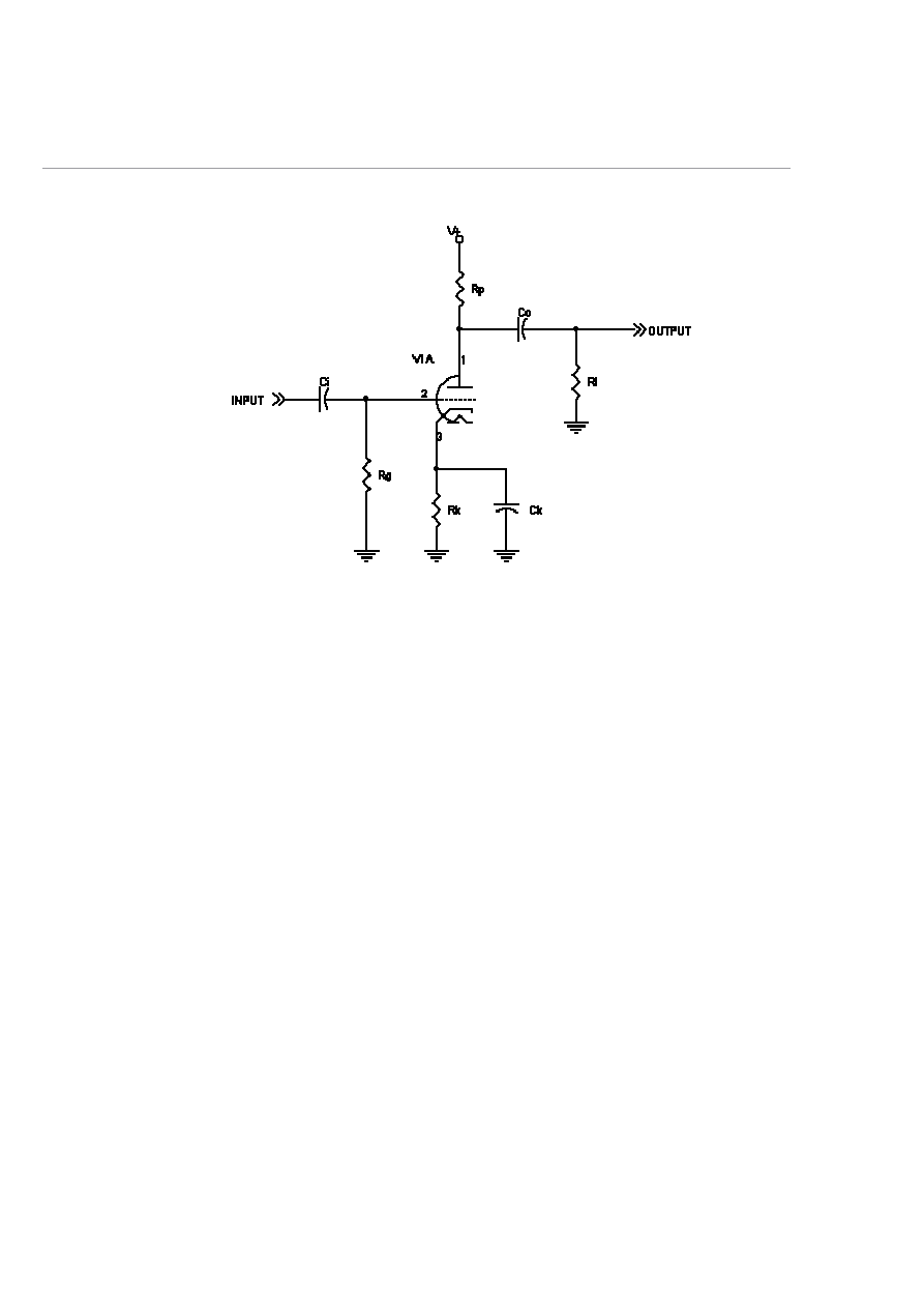
Common-cathode stage, fully-bypassed cathode:
Voltage Gain:
Av = (mu * Rp)/(Rp + r
a
)
Input impedance:
Rin = Rg
Output impedance (plate):
Rout = (r
a
* Rp)/(r
a
+ Rp)
Output impedance (cathode):
Rk' = (Ra+r
a
)/(mu+1)
Rout = Rk'||Rk
Input capacitance:
Cin =Cgk + Cgp*(Av + 1)
Frequency response:
f1 = 1/(2*pi*Ci*Rg) - highpass breakpoint due to Ci/Rg
f2 = 1/(2*pi*Co*(Rout + Rl)) - highpass breakpoint due to Co/Rout/Rl
f3 = 1/(2*pi*Ck*Rk'||Rk) - highpass breakpoint due to Ck/Rk
f4 = 1/(2*pi*Rout*Cin) - lowpass breakpoint due to Rout of previous stage and Cin
Where:
Rg = the grid resistor
Rp = the plate resistor
Rl = the load resistance, or the input resistance of the next stage
Ra = the total load resistance, which is Rp in parallel with the input resistance of the next stage,
Rl. If there is no Rl, Ra = Rp.
r
a
= the internal plate resistance of the tube
mu = the mu of the tube
Cgk = the grid-to-cathode capacitance
2
Cgp = the grid-to-plate capacitance
Av = the stage voltage gain
Note that Rl is ignored in the output impedance calcuations for the output, not because it doesn't affect output
impedance of the overall circuit, but because output impedance is traditionally the impedance of the output of that
gain stage looking back into the output. Rl is the input impedance of the following stage, so it is not included. Of
course, when calculating overall gain in an amplifier, the loading effect of Rl must be taken into account. In the
case of the cathode impedance, Rl must be included because it will affect the impedance seen looking back into the
cathode.
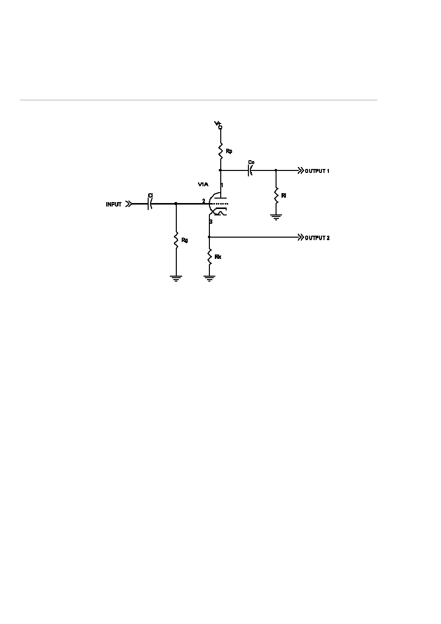
Common-cathode stage, unbypassed cathode:
Voltage Gain (Output 1):
Av = (mu * Rp)/(Rp + r
a
+ (mu + 1)*Rk)
Input impedance:
Rin = Rg
Output impedance (Output 1):
Rout = [(r
a
+ (mu + 1)*Rk) * Rp] / [(r
a
+ (mu + 1)*Rk) + Rp]
Output impedance (Output 2):
Rout = [(Ra + r
a
)/(mu + 1) * Rk] / [(Ra + r
a
)/(mu + 1) + Rk]
Frequency response (Output 1):
f1 = 1/(2*pi*Ci*Rg) - highpass breakpoint due to Ci/Rg
f2 = 1/(2*pi*Co*(Rout + Rl)) - highpass breakpoint due to Co/Rout/Rl
Where:
Rg = the grid resistor
Rp = the plate resistor
Rk = the cathode resistor
Rl = the load resistance, or the input resistance of the next stage
Ra = the total load resistance, which is Rp in parallel with the input resistance of the next stage,
Rl. If there is no Rl, Ra = Rp.
r
a
= the internal plate resistance of the tube
mu = the mu of the tube
Note that Rl is ignored in the output impedance calcuations for output 1, not because it doesn't affect output
impedance of the overall circuit, but because output impedance is traditionally the impedance of the output of that
gain stage looking back into the output. Rl is the input impedance of the following stage, so it is not included. Of
course, when calculating overall gain in an amplifier, the loading effect of Rl must be taken into account. In the
case of the output taken from the cathode, Rl must be included because it will affect the impedance seen looking
back into the cathode.
3
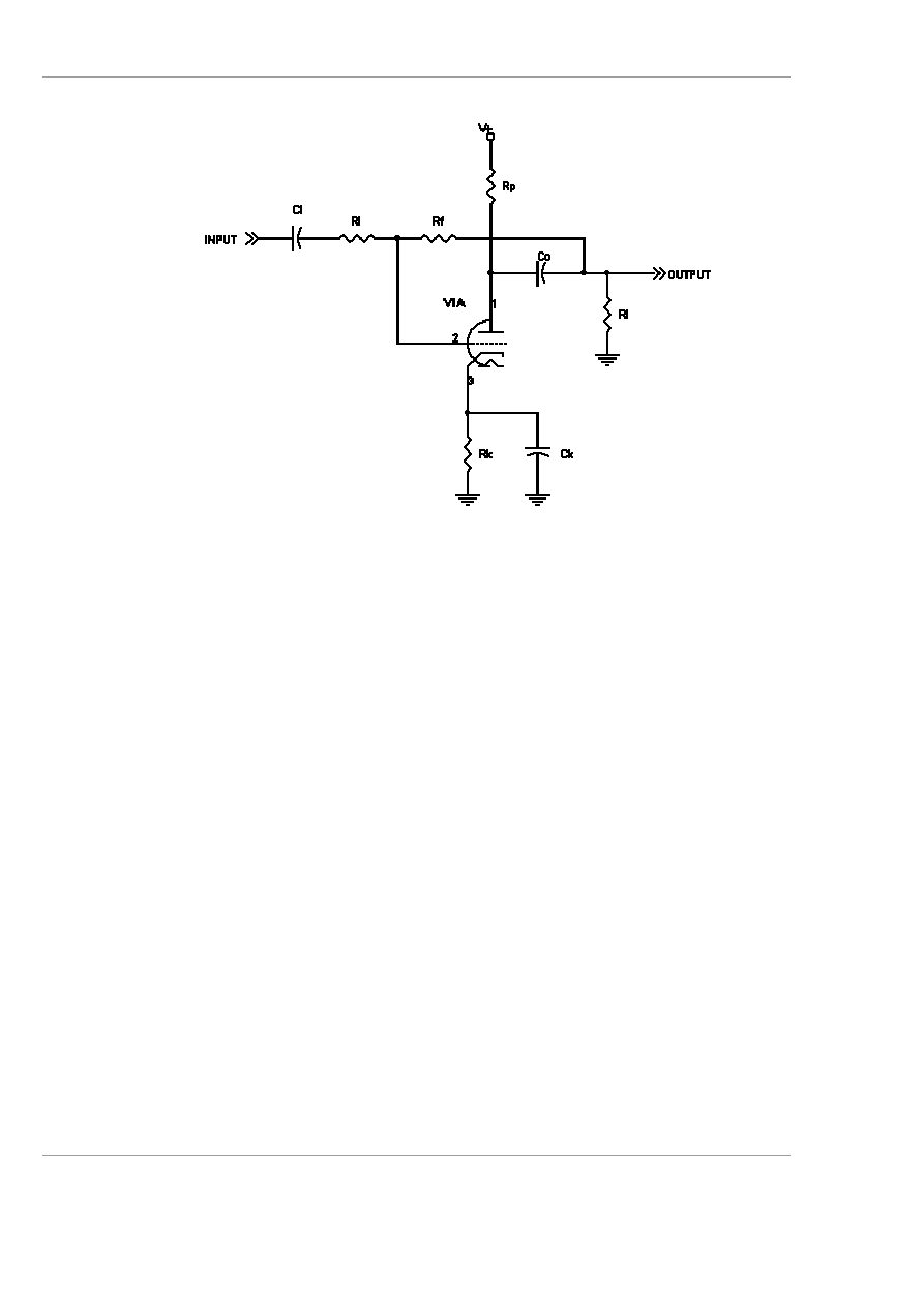
Single-stage inverting feedback amplifier:
.
Gain:
Acl = (Ro + A*Rf) / (Ri + Rf + Ro - Ri*A)
Input impedance:
Rin = (Ri * A - Ri - Rf - Ro)/(A-1)
Output impedance:
Rout = (Ri + Rf) * [Ro / (Ri + Rf + Ro - Ri*A)]
Frequency response:
f1 = 1/(2*pi*Ci*Ri) - highpass breakpoint due to Ci/Ri
f2 = 1/(2*pi*Co*(Rout + Rl)) - highpass breakpoint due to Co/Rout/Rl
Where:
Acl = closed loop gain
A = open loop gain
Ri = input resistance
Rf = feedback resistance
Ro = internal output resistance of the stage (the plate load resistor in parallel with the internal plate
resistance, r
a
, of the tube, plus the reactance of Co, if not negligible at the frequency of interest)
Note that for negative feedback, A must be a negative quantity. If A is positive, the feedback will
be positive. The value of A can be calculated by using the equations for the common cathode
amplifier stage.
Note that Rl is ignored in the output impedance calcuations, not because it doesn't affect output
impedance of the overall circuit, but because output impedance is traditionally the impedance of
the output of that gain stage - Rl is the input impedance of the following stage, so it is not
included. Of course, when calculating overall gain in an amplifier, the loading effect of Rl must
be taken into account.
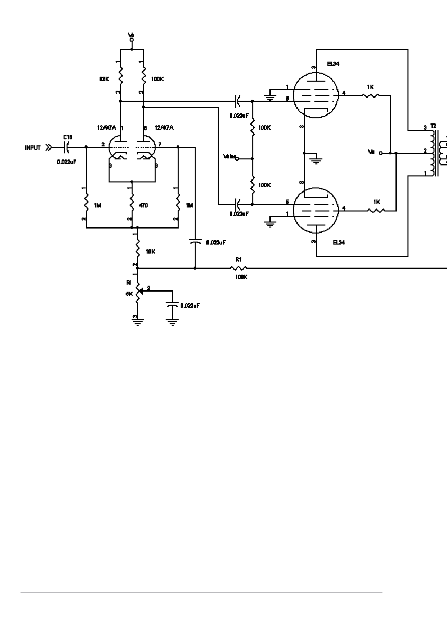
Global negative feedback amplifier:
4
Gain:
Acl = A*(Ri+Rf) / (Ri + Rf + Ro + Ri*A)
Note: if Ro is assumed zero, Acl= A / (1 + A* Ri / (Ri + Rf))
Input impedance:
Rin = Rg / (1V - Acl*Ri/(Ri+Rf))
Note: If closed loop gain is high enough, Rin is essentially infinite
Output impedance:
Rout = ((Ri + Rf) * Ro) / (Ri + Rf + Ro + Ri*A)
Note: if Ro is assumed zero, Rout = 0.
Where:
A = open-loop gain
Acl = closed-loop gain
A = open loop gain
Ri = input resistance
Rf = feedback resistance
Ro = internal output resistance
Note that for negative feedback, A must be a positive quantity. If A is negative, the feedback will
be positive. The value of A can be determined by opening the loop and measuring the output
voltage and dividing by the applied input voltage.
5
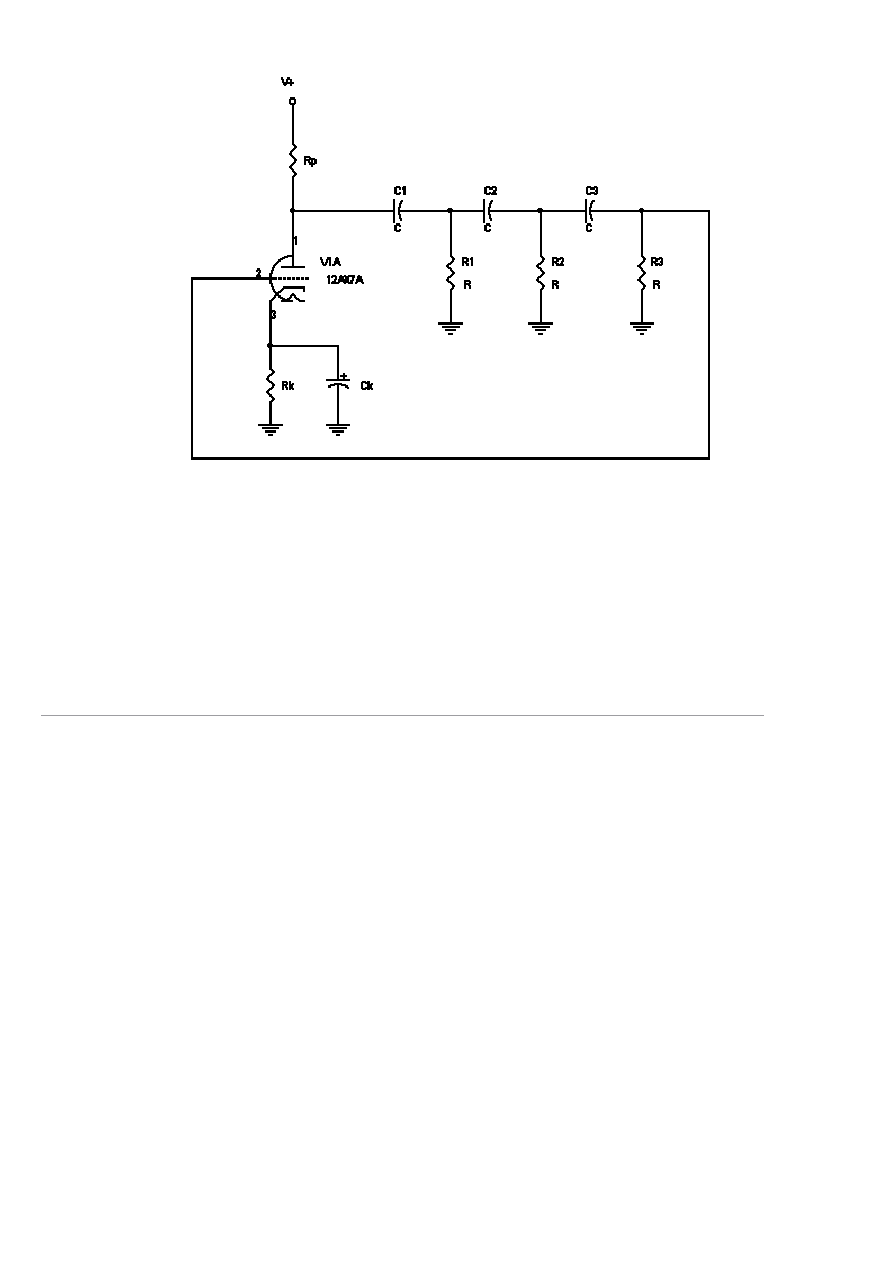
Phase-shift oscillator:
Minimum gain required for oscillation:
A(min) = 29
The value of A can be calculated by using the equations for the common cathode amplifier stage.
It must be 29 or greater to sustain oscillations. A gain of exactly 29, or just enough to sustain
oscillations, will produce the lowest distortion sine wave at the plate of the tube.
Oscillation frequency:
f
o
= 1/(2*Pi*Sqrt(6)*R*C)
Impedance and frequency scaling
Impedance scaling
Impedance scaling is accomplished by first calculating an impedance scaling factor, ZSF, as
follows:
ZSF = Znew/Zold
The impedance-scaled values are then calculated using the following formulas:
R' = R*ZSF
L' = L*ZSF
C' = C/ZSF
Frequency scaling
Frequency scaling is accomplished by first calculating a frequency scaling factor, FSF as follows:
FSF = desired frequency/existing frequency
The frequency-scaled values are calculated as follows:
R' = R
L' = L/FSF
C' = C/FSF
Frequency and impedance scaling
Both frequency and impedance scaling can be accomplished in one step with the following
equations:

6
R' = R*ZSF
L' = (L*ZSF)/FSF
C' = C/(ZSF*FSF)
where
R', L', and C' are the resistance, inductance, and capacitance values after
impedance scaling
Wyszukiwarka
Podobne podstrony:
Design of an Audio Frequency Vacuum Tube Amplifier Brad Bryant 2000
Vacuum Tube Sch Amplifier EL84
32 425 436 Ifluence of Vacuum HT on Microstructure and Mechanical Properties of HSS
Mikkelsen Copular Clauses Specification, predication and equation (Linguistik Aktuell 85)
Heathkit AA 151 Stereo Amplifier Assembly and Operation manual
OPA134PA Input Stage Amplifier Circuit 588x230 AnytoPDF
Modeling and minimizing process time of combined convective and vacuum drying of mushrooms and parsl
Single 300B Tube Amplifier WE91A
Improving nutritional value of dried blueberries combining microwave vacuum, hot air drying and free
Combined osmotic and microwave vacuum dehydration of Apple and strawberries
Heathkit AA 151 Stereo Amplifier Assembly and Operation manual
Power Amplifiers With Valves An Approach And A Practical Circuit (Claus Byrith)
Rodrigues & Vaz SUBLUMINAL AND SUPERLUMINAL SOLUTIONS IN VACUUM OF THE MAXWELL EQUATIONS AND THE MA
Drying kinetics and drying shrinkage of garlic subjected to vacuum microwave dehydration (Figiel)
Complete Circuit diagram and plans
Complex Numbers and Ordinary Differential Equations 36 pp
więcej podobnych podstron