
296
Chapter 7 Exergy Analysis
Analysis:
The state at the inlet is specified. The state at the exit can be fixed by reducing the steady-state mass and energy
rate balances to obtain
Thus, the exit state is fixed by p
2
and h
2
. From Table A-4, h
1
3043.4 kJ/s, s
1
Interpolating at a pressure
of 0.5 MPa with h
2
h
1
, the specific entropy at the exit is s
2
Evaluating h
0
and s
0
at the saturated liquid
state corresponding to T
0
, Table A-2 gives h
0
104.89 kJ/kg, s
0
Dropping V
2
2 and gz, we obtain the specific flow exergy from Eq. 7.20 as
Substituting values into the expression for e
f
, the flow exergy at the inlet is
At the exit
With assumptions listed, the steady-state form of the exergy rate balance, Eq. 7.35, reduces to
Dividing by the mass flow rate
and solving, the exergy destruction per unit of mass flowing is
Inserting values
Since h
1
h
2
, this expression for the exergy destruction reduces to
Thus, the exergy destruction can be determined knowing only T
0
and the specific entropies s
1
and s
2
. The foregoing equa-
tion can be obtained alternatively beginning with the relationship
and then evaluating the rate of entropy pro-
duction
from an entropy balance.
Energy is conserved in the throttling process, but exergy is destroyed. The source of the exergy destruction is the uncon-
trolled expansion that occurs.
s
#
cv
E
#
d
T
0
s
#
cv
E
#
d
m
#
T
0
1s
2
s
1
2
E
#
d
m
#
1073.89 836.15 237.7 kJ/kg
E
#
d
m
#
1e
f1
e
f2
2
m
#
0
a
j
a1
T
0
T
j
b
0
Q
#
j
W
#
cv
0
m
#
1e
f1
e
f2
2 E
#
d
e
f2
13043.4 104.892 29817.4223 0.36742 836.15 kJ/kg
e
f1
13043.4 104.892 29816.6245 0.36742 1073.89 kJ/kg
e
f
h h
0
T
0
1s s
0
2
0.3674 kJ/kg
# k.
7.4223 kJ/kg
# k.
6.6245 kJ/kg
# k.
h
2
h
1
❷
❷
❶
Although heat exchangers appear from an energy perspective to operate without loss when
stray heat transfer is ignored, they are a site of thermodynamic inefficiency quantified by ex-
ergy destruction. This is illustrated in the next example.
E X A M P L E
7 . 6 Exergy Destruction in a Heat Exchanger
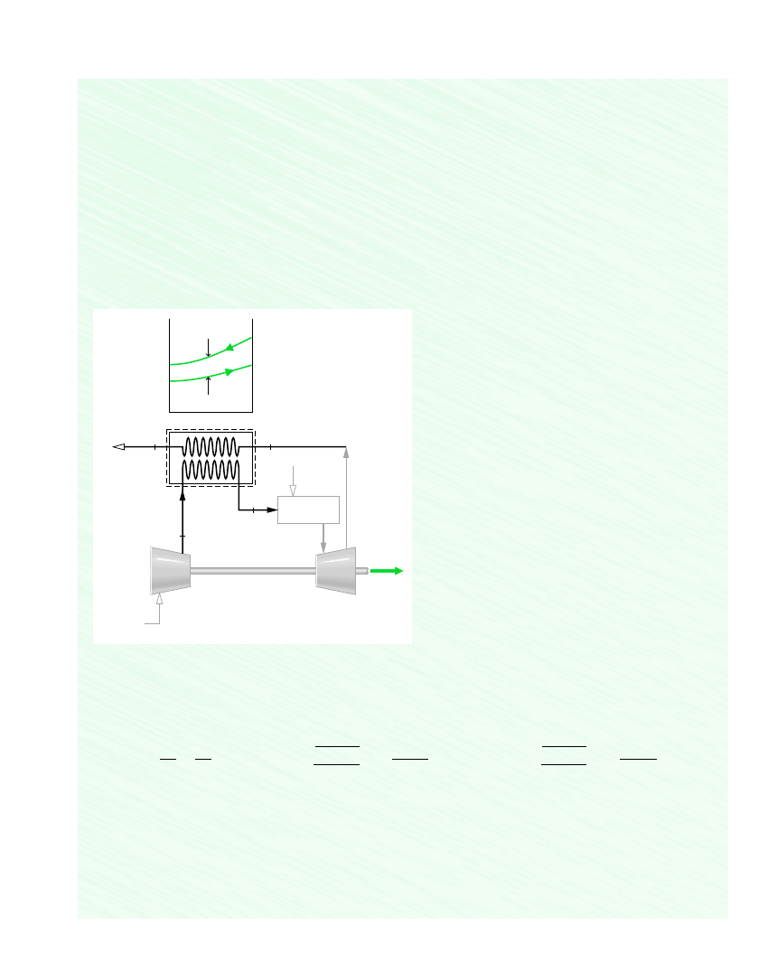
Compressed air enters a counterflow heat exchanger operating at steady state at 610 K, 10 bar and exits at 860 K, 9.7 bar. Hot
combustion gas enters as a separate stream at 1020 K, 1.1 bar and exits at 1 bar. Each stream has a mass flow rate of 90 kg/s.
Heat transfer between the outer surface of the heat exchanger and the surroundings can be ignored. Kinetic and potential energy
effects are negligible. Assuming the combustion gas stream has the properties of air, and using the ideal gas model for both
streams, determine for the heat exchanger
❶
❶
7.5 Exergy Rate Balance for Control Volumes
297
T
2
= 860 K
p
2
= 9.7 bar
T
1
= 610 K
p
1
= 10 bar
T
3
= 1020 K
p
3
= 1.1 bar
T
4
T
3
∆T
ave
T
2
T
1
p
4
= 1 bar
1
2
3
4
Compressor
Air
Turbine
Fuel
Combustion
gases
Combustor
Assumptions:
1.
The control volume shown in the accompanying figure
is at steady state.
2.
For the control volume,
and changes
in kinetic and potential energy from inlet to exit are
negligible.
3.
Each stream has the properties of air modeled as an
ideal gas.
4.
T
0
300 K, p
0
1 bar.
Q
#
cv
0, W
#
cv
0,
Analysis:
(a)
The temperature T
4
of the exiting combustion gases can be found by reducing the mass and energy rate balances for the
control volume at steady state to obtain
where
is the common mass flow rate of the two streams. The underlined terms drop out by listed assumptions, leaving
Dividing by
and solving for h
4
From Table A-22, h
1
617.53 kJ/kg, h
2
888.27 kJ/kg, h
3
1068.89 kJ/kg. Inserting values
Interpolating in Table A-22 gives T
4
778 K (505C).
h
4
1068.89 617.53 888.27 798.15 kJ/kg
h
4
h
3
h
1
h
2
m
#
0
m
# 1h
1
h
2
2 m
# 1h
3
h
4
2
m
#
0
Q
#
cv
W
#
cv
m
# c 1h
1
h
2
2 a
V
2
1
V
2
2
2
b g1z
1
z
2
2 d m
# c 1h
3
h
4
2 a
V
2
3
V
2
4
2
b g1z
3
z
4
2 d
(a)
the exit temperature of the combustion gas, in K.
(b)
the net change in the flow exergy rate from inlet to exit of each stream, in MW.
(c)
the rate exergy is destroyed, in MW.
Let T
0
300 K, p
0
1 bar.
S O L U T I O N
Known:
Steady-state operating data are provided for a counterflow heat exchanger.
Find:
For the heat exchanger, determine the exit temperature of the combustion gas, the change in the flow exergy rate from
inlet to exit of each stream, and the rate exergy is destroyed.
Schematic and Given Data:
Figure E7.6
❷

298
Chapter 7 Exergy Analysis
(b)
The net change in the flow exergy rate from inlet to exit for the compressed air stream can be evaluated using Eq. 7.36,
neglecting the effects of motion and gravity. With Eq. 6.21a and data from Table A-22
Thus, as the air passes from 1 to 2, its flow exergy increases.
Similarly, the change in the flow exergy rate from inlet to exit for the combustion gas is
Thus, as the combustion gas passes from 3 to 4, its flow exergy decreases.
(c)
The rate of exergy destruction within the control volume can be determined from an exergy rate balance
Solving for
and inserting known values
Comparing results, we see that the exergy increase of the compressed air stream is less than the exergy decrease of the com-
bustion gas stream, even though each has the same energy change. The difference is accounted for by exergy destruction.
Energy is conserved but exergy is not.
Heat exchangers of this type are known as regenerators (see Sec. 9.7).
The variation in temperature of each stream passing through the heat exchanger is sketched in the schematic.
Alternatively, the rate of exergy destruction can be determined using
is the rate of entropy produc-
tion evaluated from an entropy rate balance. This is left as an exercise.
Exergy is destroyed by irreversibilities associated with fluid friction and stream-to-stream heat transfer. The pressure drops
for the streams are indicators of frictional irreversibility. The temperature difference between the streams is an indicator
of heat transfer irreversibility.
E
#
d
T
0
s
#
cv
, where s
#
cv
114.1 MW2 116.93 MW2 2.83 MW
E
#
d
m
#
1e
f1
e
f2
2 m
#
1e
f3
e
f4
2
E
#
d
0
a
j
a1
T
0
T
j
b
0
Q
#
j
W
#
cv
0
m
#
1e
f1
e
f2
2 m
#
1e
f3
e
f4
2 E
#
d
16,934
kJ
s
`
1 MW
10
3
kJ/s
` 16.93 MW
90
c 1798.15 1068.892 300
a2.68769 2.99034
8.314
28.97
ln
1
1.1
b d
m
#
1e
f4
e
f3
2 m
# c 1h
4
h
3
2 T
0
as
4
°
s
3
°
R ln
p
4
p
3
b d
14,103
kJ
s
`
1 MW
10
3
kJ/s
` 14.1 MW
90
kg
s
c 1888.27 617.532
kJ
kg
300 K
a2.79783 2.42644
8.314
28.97
ln
9.7
10
b
kJ
kg
# K
d
m
# c 1h
2
h
1
2 T
0
as
2
°
s
1
°
R ln
p
2
p
1
b d
m
#
1e
f2
e
f1
2 m
#
1h
2
h
1
2 T
0
1s
2
s
1
2
❸
❹
❶
❷
❸
❹
The next two examples provide further illustrations of exergy accounting. The first in-
volves the steam turbine with stray heat transfer considered previously in Ex. 6.6.
Wyszukiwarka
Podobne podstrony:
Moran,Shapiro Fundamentals of Engineering Thermodynamics SI Version 5th Ed 252 255
Moran,Shapiro Fundamentals of Engineering Thermodynamics SI Version 5th Ed 249 250
Engineering Fundamentals of Digital Electronics
Fundamentals of Polymer Chemist Nieznany
Engineering Thermoplastics, Overview
Fundamentals of Zen Meditation
HRMH1030/8541
Fundamentals of Project Management 4th ed J Heagney (AMACOM, 2012)
Pomiar prTź¦ůnoci pary nasyconej SI VERSION
Belyaev Fundamentals of Geometry
Dan Millman Way of the Peaceful Warrior Version (v3 0) (doc)
Bao Yen Tsui J Fundamentals of Global Positioning System Receivers[c] A Software Approach (2000)(2 n
więcej podobnych podstron