
Paper feeder
PF-60
PF-60

PF-60
Conventions
Throughout this manual, the following conventions are used:
Italic letters refer related chapters or sections or documentations.
This symbol followed by
WARNING
denotes that the following paragraph(s) includes
precautions which, if ignored, could result in personal injury, and/or irrevocable
damage to the paper feeder.
When followed by
CAUTION
this symbol denotes that the following paragraph(s)
include the precautions which, if ignored, could result in damage to the paper feeder.

PF-60
About the chapters
The manual is comprised of the following chapters:
Chapter 1:
Product Information
Chapter 2:
Installation
Chapter 3:
Maintenance
Chapter 4:
Operation Overview
Chapter 5:
Disassembly
Chapter 6:
Troubleshooting
Chapter 7:
Paper Specifications
Appendix A: Diagrams
Contents
Contents
Contents

PF-60
REVISION HISTORY
TO OBTAIN THE LATEST PRINTER DRIVERS AND UTILITIES, VISIT US AT OUR INTERNET HOME
PAGE: http://www.kyocera.com/w2k
Version
Date
Replaced Pages
Remarks
1.00
2-Apr-2001
-

Chapter 1
P r o d u c t I n f o r m a t i o n

Chapter 1 Contents
1-1 Specifications ................................................................................................................................... 1-3
1-2 Names of parts ................................................................................................................................. 1-4

PF-60
1-3
1-1 Specifications
Table 1-1-1 Specifications
Item
Description
Compatible printer
Kyocera Mita Page Printers
FS-1800/1800N and FS-3800/3800N
Number of paper cassettes
1
Paper sizes
Legal size and A5 to A4/letter universal cassette
14.8 to 21.0 cm
×
21.6 to 29.7 cm
(5-13/16 to 8-1/2
×
8-1/4 to 11-11/16 inches)
Paper capacity
500 sheets maximaum, 80 g/m
2
(16 to 28 lb/ream)
Environmental requirements Temperature: 10 to 32.5
°
C (50 to 90.5
°
F)
Humidity: 20 to 80 % RH
Ideal conditions are 20
°
C/65 % RH, altitude under 2000 m.
Dimensions
Width: 34.5 cm (13-9/16 inches)
Height: 10.5 cm (4-1/8 inches)
Depth: 45.2 cm (17-13/16 inches)
Weight
3.6 kg (7-15/16 lb.)
Power supply
Supplied from printer
1-4
PF-60
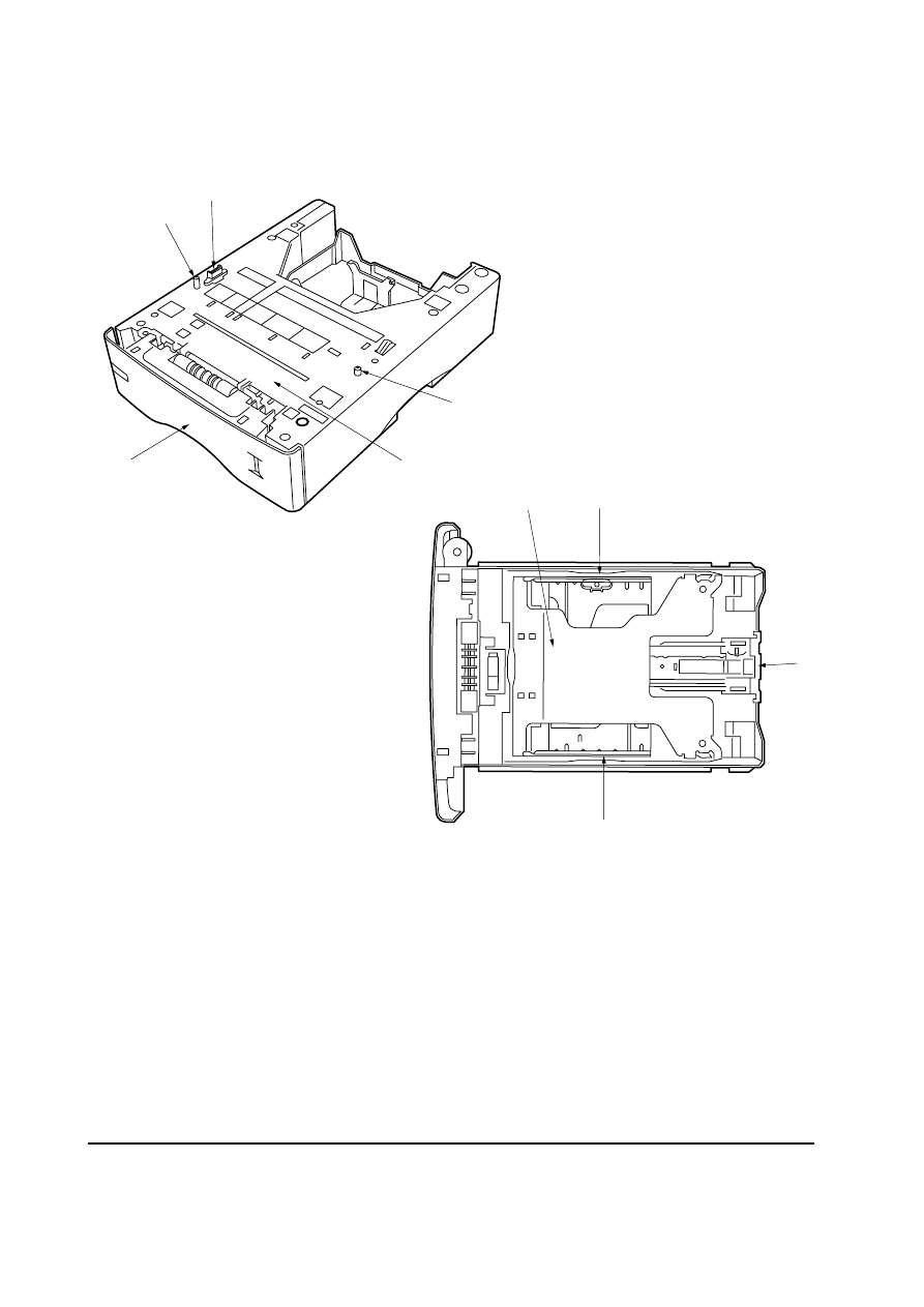
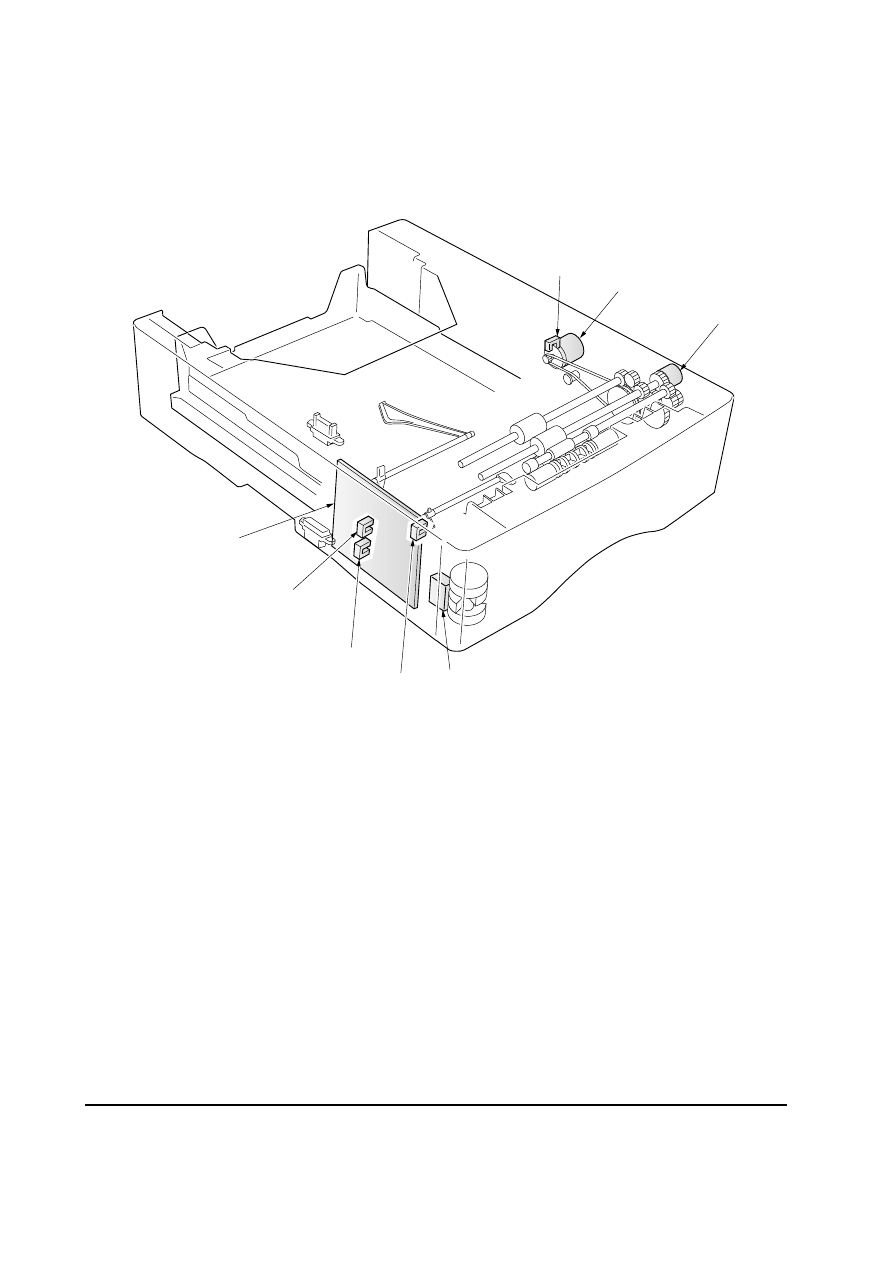
1-2 Names of parts
1 Interface connector
2 Positioning pins
3 Paper cassette
4 Top cover assembly
5 Bottom plate
6 Paper guides
7 Paper stopper
Figure 1-2-1 Names of parts
1
2
3
2
4
5
6
6
7

Chapter 2
I n s t a l l a t i o n

Chapter 2 Contents
2-1 Installing the paper feeder .............................................................................................................. 2-3
PF-60
2-3
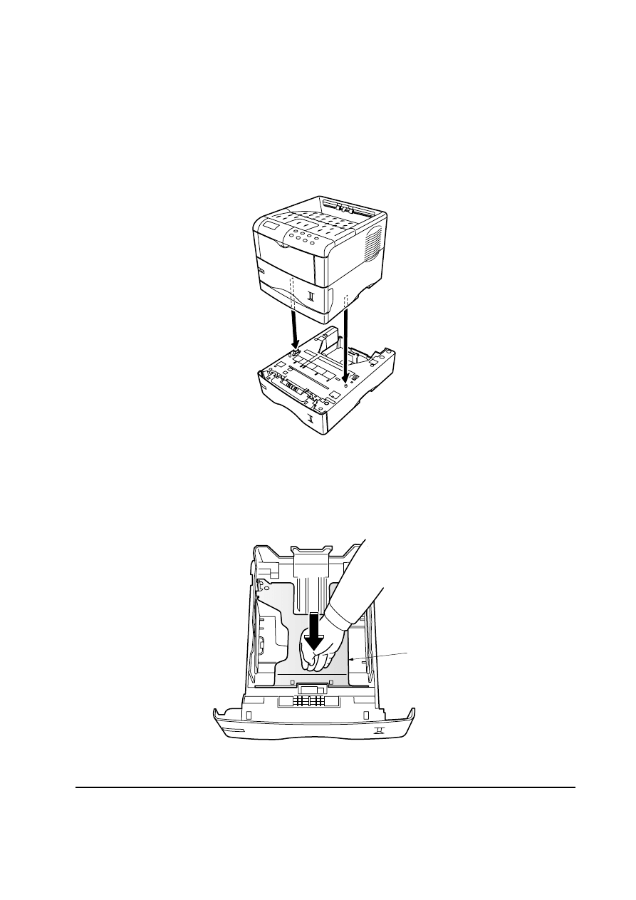
2-1 Installing the paper feeder
Note: When installing more than one paper feeder, first stack the paper feeders together.
1. Turn off the printer and disconnect the power cord and printer cable. Gently place the printer on
top of the paper feeder(s).
2. Pull the paper cassette all the way out of the paper feeder. Push down the bottom plate
1 until it
locks.
Figure 2-1-1 Place the printer
Figure 2-1-2 Push down the bottom plate
1
2-4
PF-60
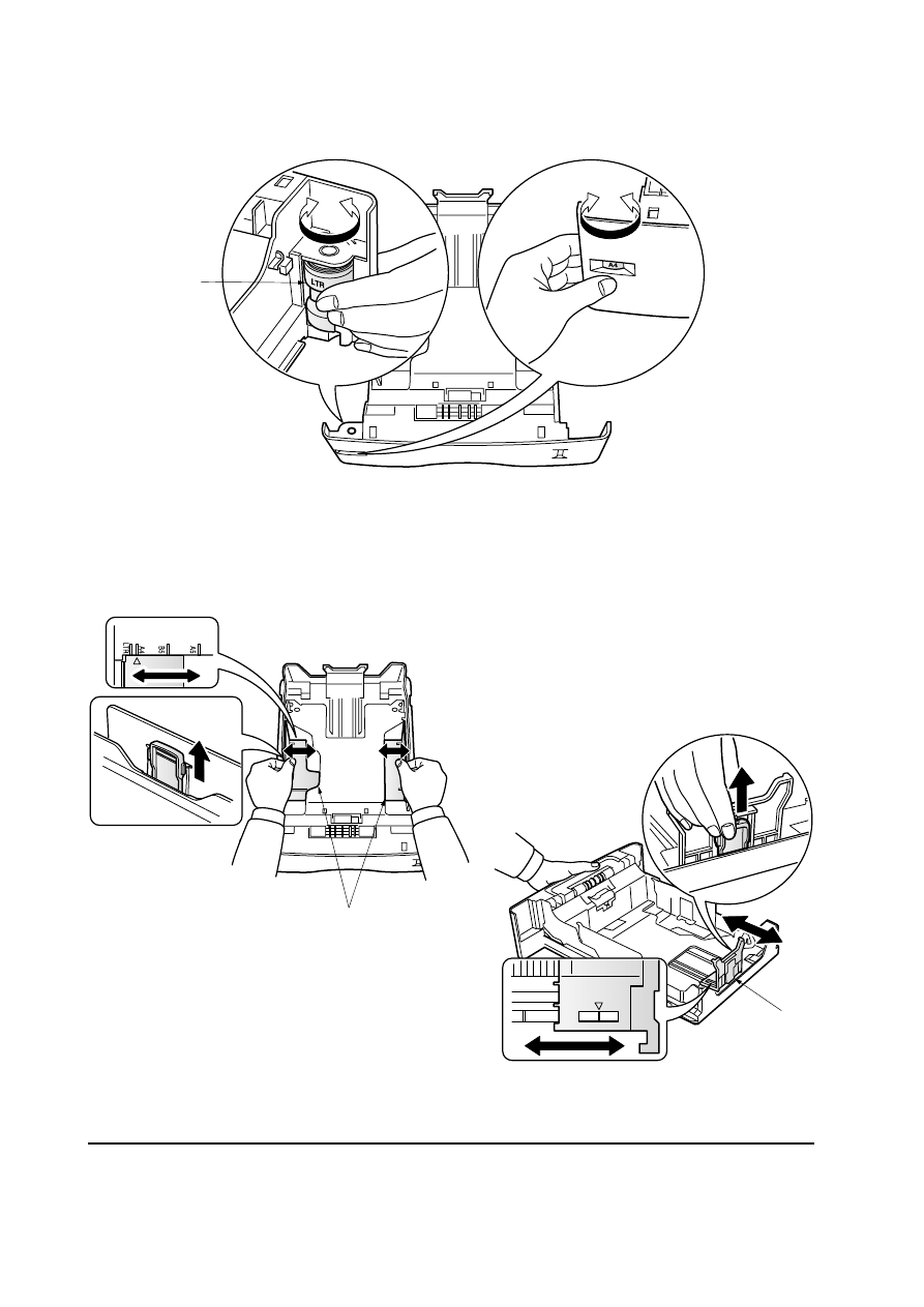
3. Set the paper size dial
2 to the size of paper to be used.
4. Adjust the paper guides
3 and paper stopper 4 to the size of paper to be used.
Figure 2-1-3 Set the paper size dial
Figure 2-1-4 Adjust the paper guides and paper stopper
2
3
B5
A4
4
PF-60
2-5
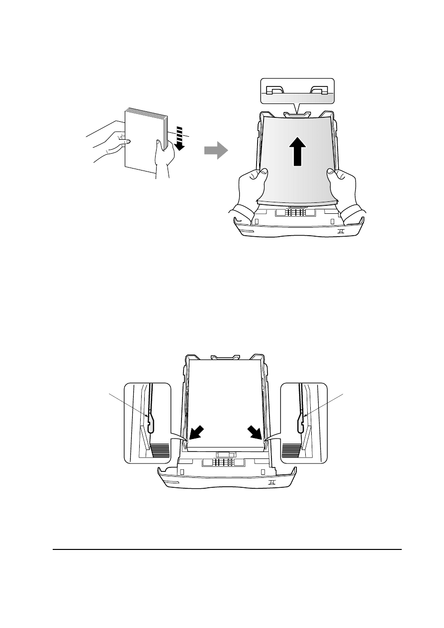
5. Load paper.
6. Set the stack of paper so that it is under the clips
5 as shown in the figure. Insert the paper
cassette back in.
Figure 2-1-5 Load paper
Figure 2-1-6 Set the stack of paper
5
5

Chapter 3
M a i n t e n a n c e

Chapter 3 Contents
3-1 Maintenance ..................................................................................................................................... 3-3
3-1-1 Cleaning the pickup roller, feed roller and conveying roller ....................................................... 3-3
3-3
PF-60
3-1 Maintenance
3-1-1 Cleaning the pickup roller, feed roller and conveying roller
Remove the top cover assembly
1. See page 5-4. Using the cleaning cloth, wipe the pickup roller
2, feed roller 3 and conveying roller 4.
Figure 3-1-1 Cleaning the pickup roller, feed roller and conveying roller
4
2
3
1

Chapter 4
O p e r a t i o n O v e r v i e w

Chapter 4 Contents
4-1 Paper feeding system ...................................................................................................................... 4-3
4-1-1 Paper feed control ..................................................................................................................... 4-4
4-1-2 Paper feeding mechanism ......................................................................................................... 4-5
4-2 Electrical control system ................................................................................................................ 4-6
4-2-1 Electrical parts layout ................................................................................................................ 4-6
4-2-2 Operation of circuit board .......................................................................................................... 4-7
(1) Paper feeder board .................................................................................................................... 4-7
4-3
PF-60
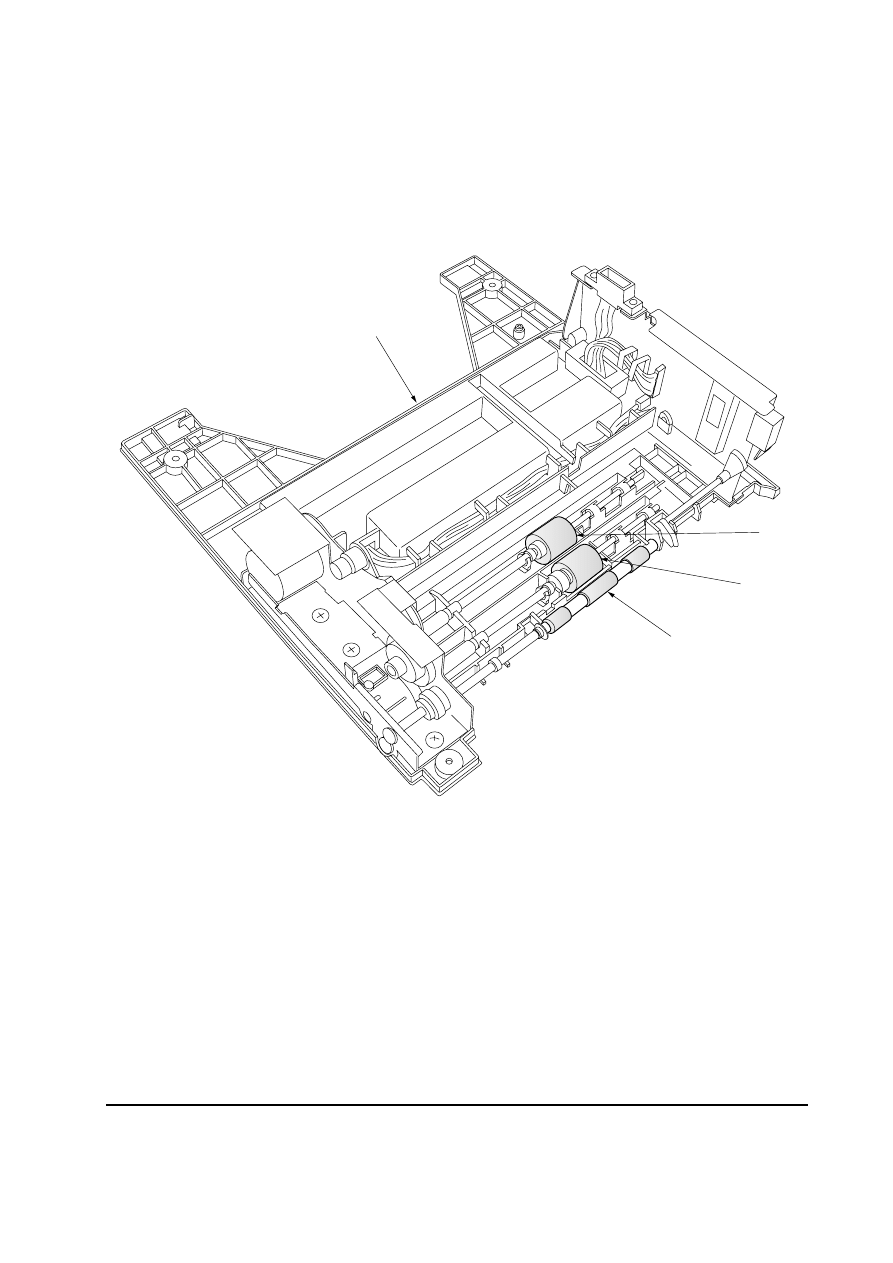
4-1 Paper feeding system
The figure below shows the components in the paper feeder and the paths through which the paper
travels. The sensors, motor etc., are described in the following pages.
1 Pickup roller
2 Feed roller
3 Retard pulley
4 Conveying roller
5 Feed pulley
Figure 4-1-1 Paper feeding path
5
2
4
3
1
4-4
PF-60
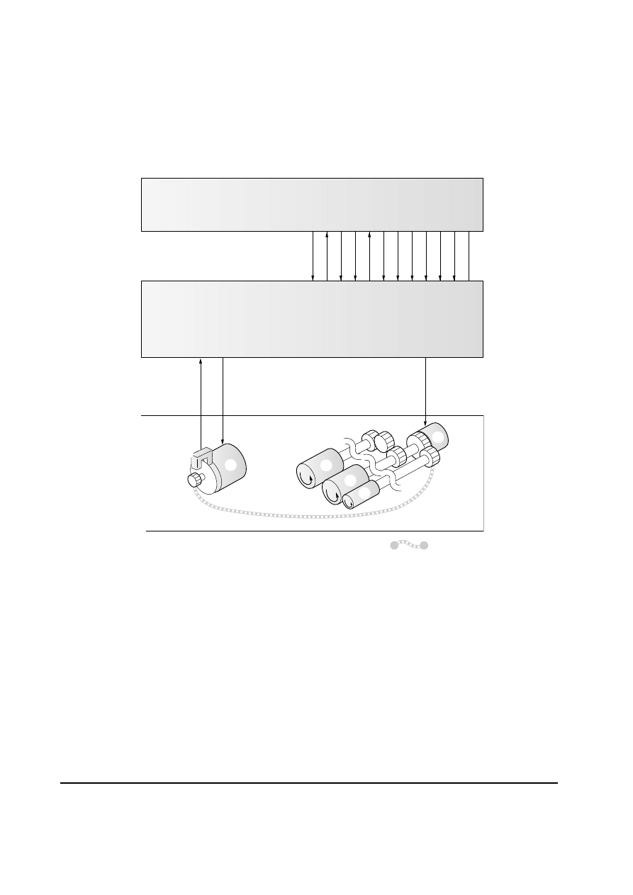
4-1-1 Paper feed control
The following diagram shows interconnectivity of the paper feeding system components
including the sensor and rollers.
The paper feeder board controls the paper feed operation. Upon reception of the paper feed
start signal from the engine board of the printer, it drives the motor and clutch.
Figure 4-1-2 Paper feed control
OP24 V
OPRDY
OPSDO
OPSCLK
OPSDI
OPSEL0
OPSEL1
OPSEL2
GND
PFSEL
OP5 V
: Power train
YC205-1
YC205-1
1
YC205-9
YC205-5
YC205-7
YC205-6
YC205-8
YC205-10
YC205-12
YC205-4
YC205-3
CN2-1
CN6-2
PFCL
MCS
PFM
CN7-1
CN1-2
CN2-2
CN2-3
CN2-4
CN2-5
CN2-6
CN2-7
CN2-8
CN2-9
CN2-10
CN2-1
1
GND
YC205-2
CN2-12
Engine board (printer)
Paper feeder board
1
5
3
2
4
6
1 Paper feed clutch
2
Pickup roller
3 Feed roller
4 Paper feed motor
5 Conveying roller
6 Motor clock sensor
4-5
PF-60
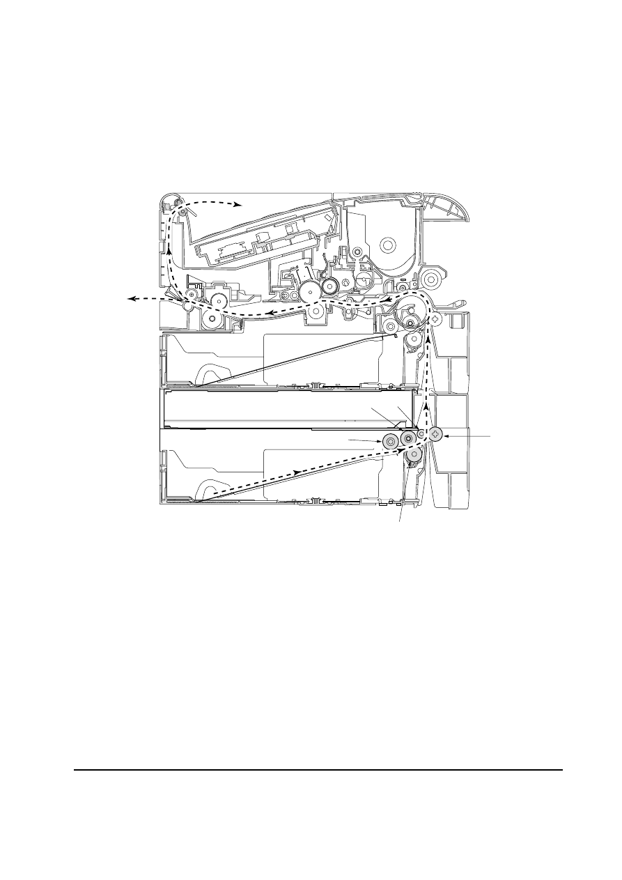
Figure 4-1-3 Paper feeding mechanism
4-1-2 Paper feeding mechanism
When a paper feed start signal is received from the engine board of the printer, the paper
feed clutch
1 turns on to rotate the pickup roller 2 and feed roller 3, to start the paper
feed operation. At this point, multiple paper feeding is prevented by the retard pulley
4. The
paper feed motor
5 then conveys the paper through the conveying roller 6 and feed pulley
7 into the printer by rotating the conveying roller 6. The paper feed sensor 8 detects
paper jams.
5
1
2
3
7
6
8
2
4
3
4-6
PF-60
1 Paper feeder board
2
Paper feed motor
3 Paper feed clutch
4 Paper gauge sensor 1
Figure 4-2-1 Electrical parts layout
4-2 Electrical control system
4-2-1 Electrical parts layout
5 Paper gauge sensor 2
6 Paper feed sensor
7 Paper size switch
8 Motor clock sensor
2
3
6
5
4
1
7
8
4-7
PF-60
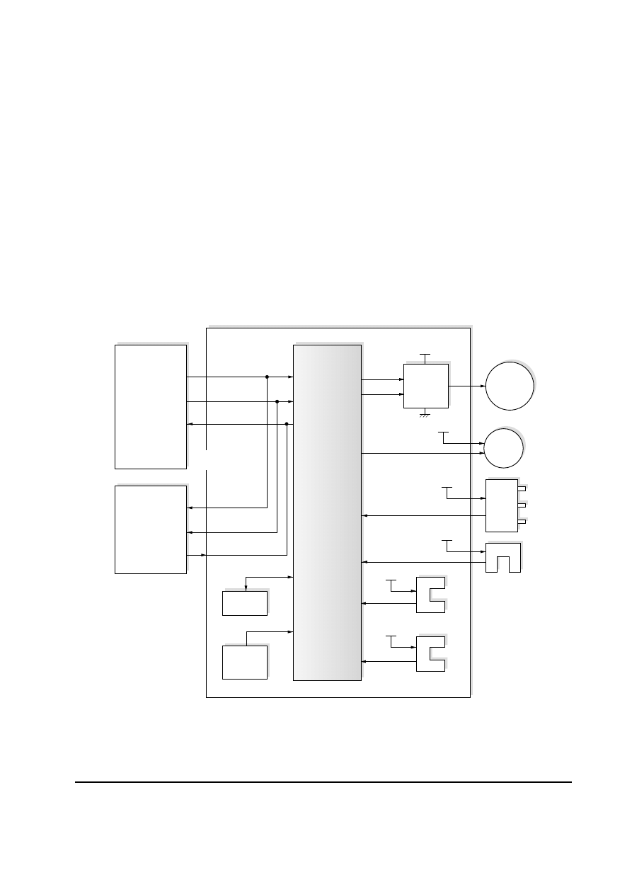
4-2-2 Operation of circuit board
(1) Paper feeder board
The paper feeder board serially communicates with the engine board of the printer and the
paper feeder board of the lower paper feeder to exchange control signals.
Upon reception of a paper feed start signal from the engine board of the printer, CPU IC3
controls the paper feed operation by operating the paper feed motor and paper feed clutch.
The motor drive circuit consists mainly of motor driver IC5. It drives the paper feed motor
based on the control signals (PFM, PWM) from CPU IC3.
The reset circuit consists mainly of reset IC1. It monitors the 5 V DC supply voltage. When
the power is turned on or when the power supply becomes low, it outputs a RESET signal to
CPU IC3, to prevent system malfunction or runaway.
Figure 4-2-2 Paper feeder board circuit block diagram
SEL [2-0],
PFSEL
OPSCLK,
OPSDO
OPREADY,
OPSDI
SEL [2-0],
PFSEL
OPSCLK,
OPSDO
OPREADY,
OPSDI
RESET
DI, DO
PFS
PGS1, 2
+24 V
PFCL
Engine board
(printer)
Paper feeder board
Reset
circuit
(IC1)
EEPROM
(IC2)
Motor
clock
sensor
Paper feed
sensor
Paper gauge
sensor 1, 2
Paper feeder
board
(middle or
bottom)
+5 V
PSSW[0-2]
MCS
+5 V
+5 V
+5 V
+24 V
PFM
PWM
Motor
drive
circuit
(IC5)
CPU
(IC3)
Paper
feed
clutch
Paper
feed
motor
Serial
communication
Paper
size
switch

Chapter 5
D i s a s s e m b l y

Chapter 5 Contents
5-1 General instructions ........................................................................................................................ 5-3
5-1-1 Screw/hardware ......................................................................................................................... 5-3
5-1-2 Before starting disassembly ...................................................................................................... 5-3
5-2 Disassembly ..................................................................................................................................... 5-4
5-2-1 Removing the top cover assembly ............................................................................................ 5-4
5-2-2 Removing the paper feeder board ............................................................................................. 5-5
5-2-3 Removing the pickup roller and feed roller ................................................................................ 5-7
5-2-4 Removing the retard pulley ........................................................................................................ 5-8
PF-60
5-3
5-1 General instructions
This chapter provides the procedure for removal and replacement of field replacement components.
For other components not explained in this chapter, the diagrams in the Parts Catalog. It is
recommended that your refer to diagrams in the Parts Catalog as a supplemental reference to this
chapter. It features all the part drawings and help you disassemble or refit the parts in the paper
feeder.
When replacing of a component, reverse the procedure for the removal procedure explained in this
chapter.
WARNING
To avoid injury electric shock, make sure that AC power is removed and the
power cord is unplugged from both the power line and the printer.
5-1-1 Screw/hardware
Screws and hardware used in the printer are listed in the Ecosys Screw catalog. These screw symbol
numbers are universal to most Ecosys printers.
CAUTION
When securing a self-tapping screws, align it with the thread carefully. First turn
it counterclockwise, then slowly clockwise. Do not overtighten. In case the self-
tapped thread is damaged, the whole part may have to be replaced with a new
part.
5-1-2 Before starting disassembly
Before proceeding, unplug the power cord from the printer and the power supply.
WARNING
Never attempt to operate the printer with components removed.
CAUTION
The paper feeder use electrostatic sensitive parts inside (circuit boards, etc.).
Provide an antistatic (discharging) device, such as a wrist strap, that can effectively
discharge your body before touching those components.
PF-60
5-4
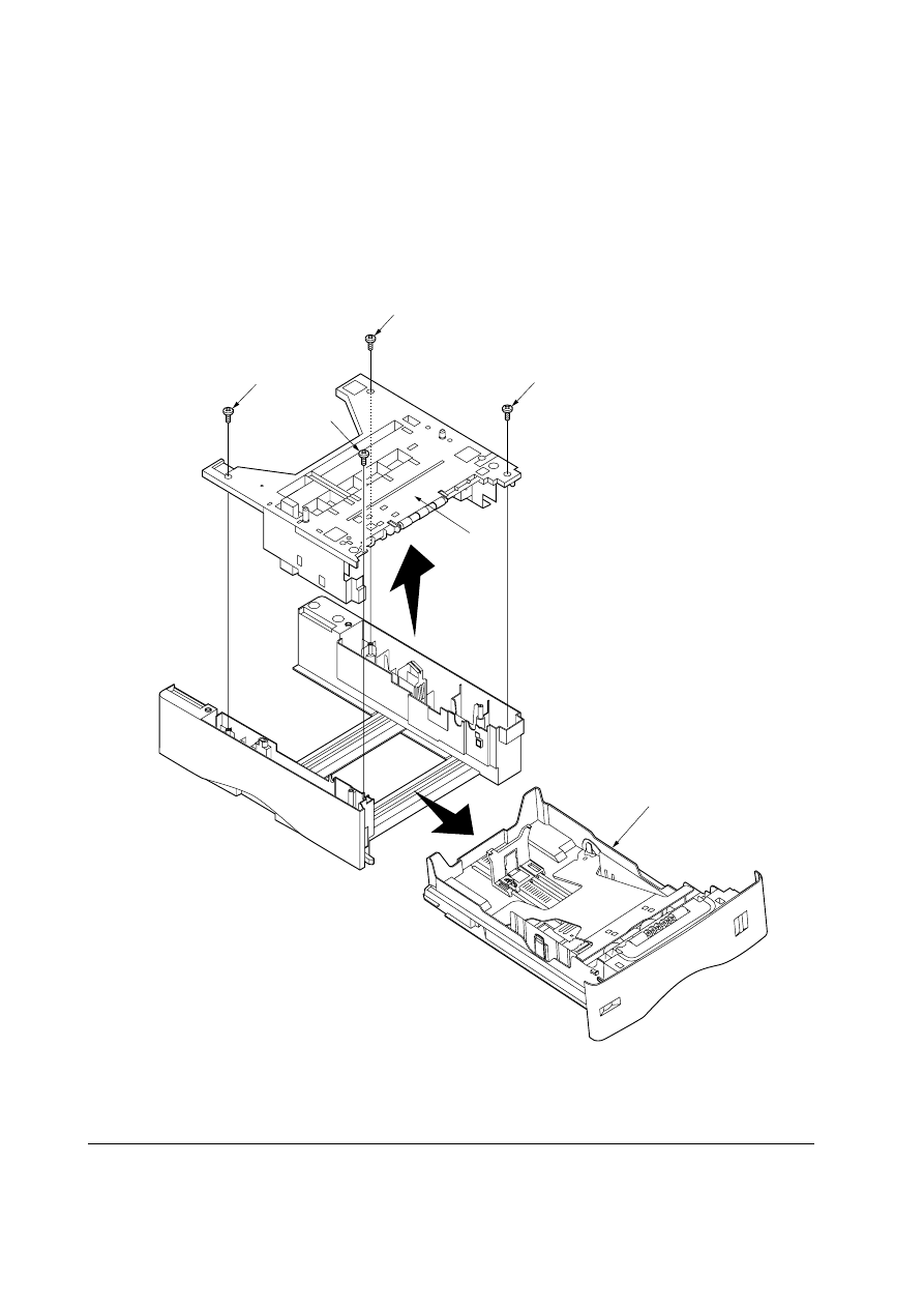
Figure 5-2-1 Removing the top cover assembly
5-2 Disassembly
5-2-1 Removing the top cover assembly
1. Pull out the paper cassette
1.
2. Remove four screws
2.
3. Remove the top cover assembly
3.
2
2
2
2
3
1
PF-60
5-5
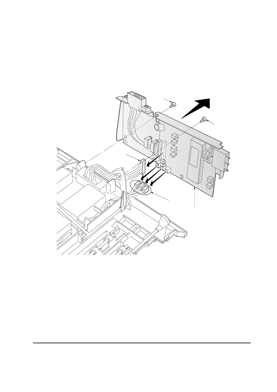
5-2-2 Removing the paper feeder board
1. Remove the top cover assembly. See page 5-4.
2. Remove two screws
1.
3. Remove four connectors
2.
4. Remove the paper feeder board assembly
3.
Figure 5-2-2 Removing the paper feeder board assembly
2
2
1
1
3
PF-60
5-6
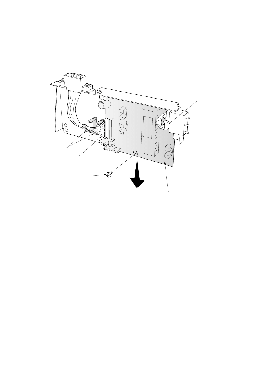
Figure 5-2-3 Removing the paper feeder board
5. Release the harness from the wire saddles
4.
6. Remove two connectors
5.
7. Remove one screw
6.
8. Remove the paper feeder board
7.
5
4
6
5
7
PF-60
5-7
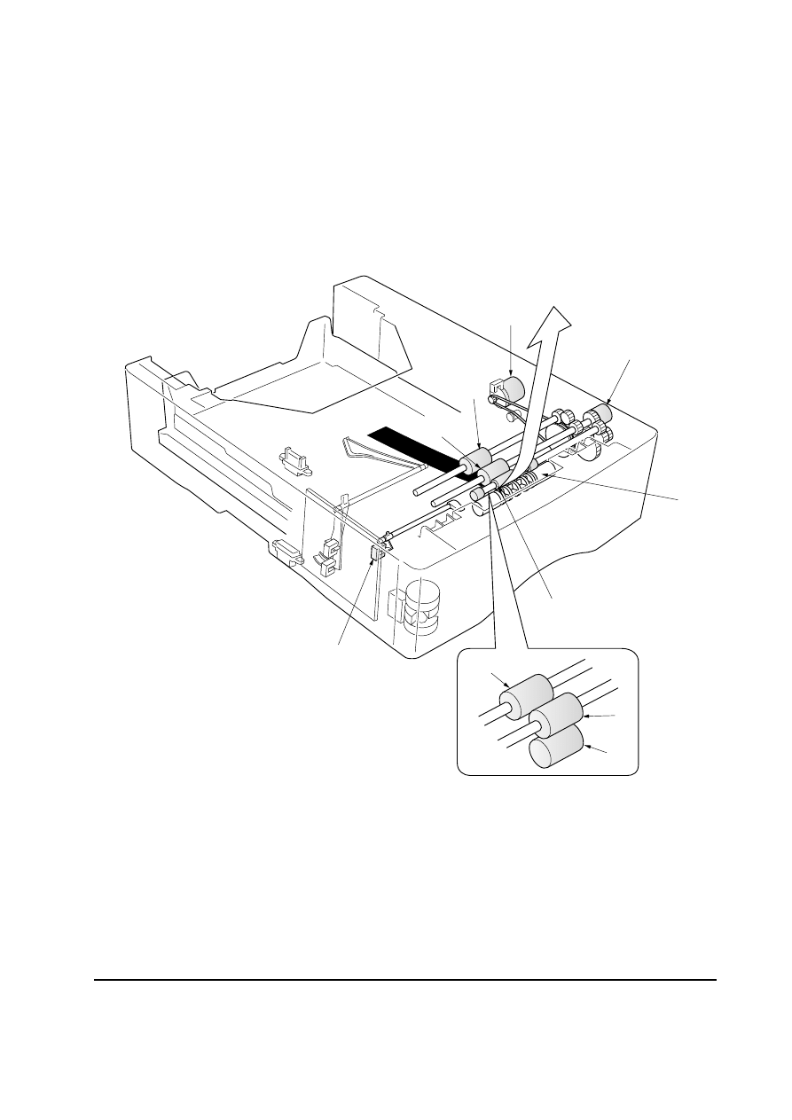
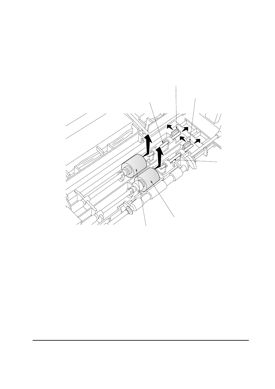
Figure 5-2-4 Removing the pickup roller and feed roller
5-2-3 Removing the pickup roller and feed roller
1. Remove the top cover assembly. See page 5-4.
2. Push the shaft lock levers
1 and slide the shafts 2 as indicated by the arrows in the below
diagram.
3. Remove the pickup roller
3 and feed roller 4.
2
2
1
1
4
3
PF-60
5-8
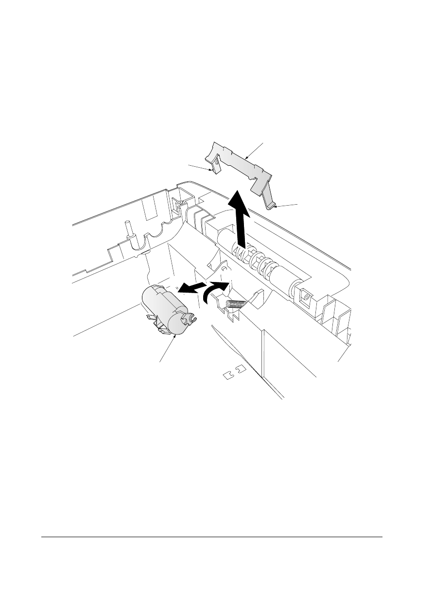
Figure 5-2-5 Removing the retard pulley
5-2-4 Removing the retard pulley
1. Remove the top cover assembly. See page 5-4.
2. Disengage the two hooks
1 of the retard guide 2 using a flat-head screwdriver or other
tool and then remove the guide.
3. Lift the retard pulley
3 in the direction of arrow a and then remove it in the direction of
arrow
b.
1
3
2
1
a
b

Chapter 6
T r o u b l e s h o o t i n g

Chapter 6 Contents
6-1 Troubleshooting ............................................................................................................................... 6-3
6-1-1 General error handling ............................................................................................................... 6-3
(1) Maintenance messages ............................................................................................................. 6-3
6-1-2 Diagnostic (Service error messages) ........................................................................................ 6-4
(1) B2
Paper feeder (Top) paper feed motor error ...................................................................... 6-4
(2) B3
Paper feeder (Middle) paper feed motor error .................................................................. 6-4
(3) B4
Paper feeder (Bottom) paper feed motor error ................................................................. 6-4
(4) C0
Paper feeder communication error ................................................................................... 6-5
6-1-3 Circuit board terminal voltages .................................................................................................. 6-6
(1) Pepar feeder board .................................................................................................................... 6-6
6-1-4 Correcting a paper jam .............................................................................................................. 6-8

6-3
PF-60
6-1 Troubleshooting
6-1-1 General error handling
(1) Maintenance messages
Message
Corrective action
Add paper
(option paper feeder)
Paper feed unit
Open
The paper has run out. Supply paper according to the paper source
displayed.
Open the paper feeder, then close tightly.
6-4
PF-60
6-1-2 Diagnostic (Service error messages)
The printer does not operate when a message is displayed. The message is categorized as follows:
(1) B2
Paper feeder (Top) paper feed motor error
Meaning
Suggested causes
Corrective action
Paper feed motor error
in the top paper feeder.
Replace paper feeder
board. See page 5-5.
R e f e r t o p r i n t e r ’ s
Service Manual.
Replace harness.
•
Defective paper feeder board.
•
Defective gate array U204 on the printer’s
engine board (KP-864).
•
Blown-out fuse (F201) on the printer’s
engine board.
•
Defective harness between paper feeder
interface connector and printer’s engine
board.
(2) B3
Paper feeder (Middle) paper feed motor error
Meaning
Suggested causes
Corrective action
Paper feed motor error
in the middle paper
feeder.
Replace paper feeder
board. See page 5-5.
R e f e r t o p r i n t e r ’ s
Service Manual.
Replace harness.
•
Defective paper feeder board.
•
Defective gate array U204 on the printer’s
engine board (KP-864).
•
Blown-out fuse (F201) on the printer’s
engine board.
•
Defective harness between paper feeder
interface connector and printer’s engine
board.
(3) B4
Paper feeder (Bottom) paper feed motor error
Meaning
Suggested causes
Corrective action
Paper feed motor error
in the bottom paper
feeder.
Replace paper feeder
board. See page 5-5.
R e f e r t o p r i n t e r ’ s
Service Manual.
Replace harness.
•
Defective paper feeder board.
•
Defective gate array U204 on the printer’s
engine board (KP-864).
•
Blown-out fuse (F201) on the printer’s
engine board.
•
Defective harness between paper feeder
interface connector and printer’s engine
board.
6-5
PF-60
Meaning
Suggested causes
Corrective action
Communication error
between paper feeder
and printer’s engine
board.
Replace paper feeder
board. See page 5-5.
F o l l o w i n s t a l l a t i o n
instruction carefully
again.
Remedy.
Refer to printer’s Service
Manual.
Replace harness.
(4) C0
Paper feeder communication error
•
Defective paper feeder board.
•
Improper installation between paper feeder
and printer.
•
Improper connector insertion.
•
Defective gate array U204 on the printer’s
engine board (KP-864).
•
Blown-out fuse (F202) on the printer’s
engine board.
•
Defective harness between paper feeder
interface connector and printer’s engine
board.
6-6
PF-60
Connector
Pin# Signal
I/O
Voltage
Function
(CN1)
1
PFCL
O
0 V/24 V DC
Paper feed clutch, On/Off
2
24 V
O
24 V DC
Power supply
(CN2)
1
24 V
I
24 V DC
Power supply from printer
2
OPRDY
O
0 V/5 V DC
Paper feeder, Ready/Not ready
3
OPSDO
I
5 V/0 V DC
Serial communication data signal
with printer
4
OPSCLK I
5 V/0 V DC (Pulse)
Serical communication clock signal
5
OPSDI
O
5 V/0 V DC
Serial communication data signal
with printer
6
OPSEL0
I
0 V/5 V DC
Paper feeder identifying signal 0
7
OPSEL1
I
0 V/5 V DC
Paper feeder identifying signal 1
8
OPSEL2
I
0 V/5 V DC
Paper feeder identifying signal 2
9
GND
–
–
Power ground
10
PFSEL
I
0 V/5 V DC
Paper feeder identifying signal
11
5 V
I
5 V DC
Power supply from printer
12
GND
–
–
Signal ground
13
–
–
–
Reserved
(CN3)
1
24 V
O
24 V DC
Power supply
2
OPRDY
I
0 V/5 V DC
Paper feeder, Ready/Not ready
3
OPSDO
O
5 V/0 V DC
Serial communication data signal
with printer
4
OPSCLK O
5 V/0 V DC (Pulse)
Serical communication clock signal
5
OPSDI
I
5 V/0 V DC
Serial communication data signal
with printer
6
OPSEL0
O
0 V/5 V DC
Paper feeder identifying signal 0
7
OPSEL1
O
0 V/5 V DC
Paper feeder identifying signal 1
8
OPSEL2
O
0 V/5 V DC
Paper feeder identifying signal 2
9
GND
–
–
Power ground
10
PFSEL
O
0 V/5 V DC
Paper feeder identifying signal
11
5 V
O
5 V DC
Power supply
12
GND
–
–
Signal ground
6-1-3 Circuit board terminal voltages
(1) Pepar feeder board

6-7
PF-60
Connector
Pin# Signal
I/O
Voltage
Function
(CN4)
1
PSSW0
I
0 V/5 V DC
Paper size switch detecting signal
2
GND
–
–
Signal ground
3
PSSW1
I
0 V/5 V DC
Paper size switch detecting signal
4
PSSW2
I
0 V/5 V DC
Paper size switch detecting signal
(CN6)
1
GND
–
–
Signal ground
2
MCS
I
0 V/5 V DC (Pulse)
Paper feed motor clock signal
3
5 V
O
5 V DC
Power supply
(CN7)
1
24 V
O
24 V DC
Power supply
2
PFM
O
0 V/24 V DC (PWM) Paper feed motor, On/Off
6-8
PF-60
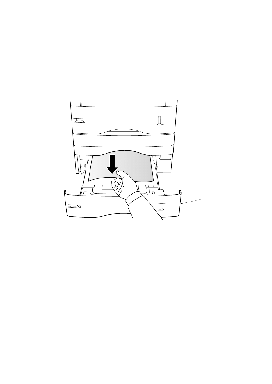
6-1-4 Correcting a paper jam
If a paper jam occurs in the paper feeder, remove the jammed paper as described below.
After you have removed the jammed paper, open and close the printer’s top cover to clear the
error message from the message display.
1. Pull out the paper cassette
1.
2. Remove the jammed paper
Figure 6-1-1 Jam in the paper feeder
1

Chapter 7
P a p e r S p e c i f i c a t i o n s

Chapter 7 Contents

7-3
PF-60
7-1 General guidelines
The paper feeder may not be used to print on paper not satisfying the requirements below. Also,
special types of print media such as overhead projection (OHP) film, envelopes, adhesive backed
labels, and paper containing watermarks must not be used with printing with the paper feeder.
These types can result in jams, misfeeds, and paper waste, and in extreme cases can damage the
paper feeder.
NOTE
Kyocera mita assumes no liability for problems that occur when paper not satisfying
these requirements is used with the paper feeder.
Selection of the right paper is important. The wrong paper can result in jams, misfeeds, curl, poor
print quality, and paper waste, and in extreme cases can damage the paper feeder and the printer.
The guidelines given below will increase the productivity of your office by ensuring efficient,
trouble-free printing and reducing wear and tear on the paper feeder and the printer.
7-1-1 Paper availability
Most types of paper are compatible with a variety of machines. Paper intended for xerographic
copiers can also be used with the paper feeder and the printer.
There are three general grades of paper: economy, standard, and premium. The most significant
difference between grades is the ease with which they pass through the printer.
This is affected by the smoothness, size, and moisture content of the paper, and the way in which
the paper is cut. The higher the grade of paper you use, the less risk there will be of paper jam and
other problems, and the higher the level of quality your printed output will reflect.
Differences between paper from different suppliers can also affect the paper feeder's performance.
A high-quality printer cannot produce high-quality results when the wrong paper is used. Low-
priced paper is not economical in the long run if causes printing problems.
Paper in each grade is available in a range of basic weights (defined later). The traditional standard
weights are 16, 20, and 28 pounds (60 g/m
2
to 105 g/m
2
).

7-4
PF-60
7-1-2 Selecting the right paper
Printer printing is a process involving laser light, electrostatic discharge, toner, and heat. In addition,
as the paper passes through the printer it undergoes considerable sliding, bending, and twisting
motions. A high-quality printing paper matching the requirements withstands all these stresses,
enabling the paper feeder and the printer to turn out clean, crisp printed copy consistently.
Remember that all paper is not the same. Some of the factors to consider when selecting paper is as
following in the next section.

7-5
PF-60
Item
Specification
Weight 60 to 105 g/m
2
(16 to 28 lbs./ream)
Thickness
0.086 to 0.110 mm (3.4 to 4.3 mils)
Dimensional accuracy
±
0.7 mm (
±
0.0276 inches)
Squareness
90
°
±
0.2
°
Moisture content
4 to 6 %
Direction of grain
Long grain
Pulp content
80 % or more
7-2-1 Points of consideration
The following section provides general information which should be considered when selecting
paper for using with the paper feeder.
(1) Condition of the paper
Avoid using paper that is bent at edges, curled, dirty, torn, or contaminated with lint, clay, or paper
shreds.
Used of paper in these conditions can lead to illegible printing, misfeeding, and paper jams, and can
shorten the life of the paper feeder and the printer. In particular, avoid using paper with a surface
coating or other surface treatment. The paper should have as smooth and even a surface as possible.
(2) Composition
Do not use paper that has been coated or surface-treated and contains plastic or carbon. The heat of
fusing can cause such paper to give off harmful fumes.
Bond paper should contain at least 80% pulp. Not more than 20% of the total paper content should
consist of cotton or other fibers.
7-2 Paper specifications
The following table summarizes the basic paper specifications that should be applied to the paper
used with the paper feeder. Details are given following the table.
Table 7-2-1 Specifications

7-6
PF-60
(3) Paper size
The paper feeder is usable with the paper sizes as tabled below.
Table 7-2-2 Paper size
Paper size
Dimension
ISO A4 210 × 297 mm
JIS B5 182
×
257 mm
ISO A5 148
×
210 mm
Letter 8-1/2 × 11 inches
Legal 8-1/2 × 14 inches
(4) Smoothness
The paper should have a smooth, uncoated surface. Paper with a rough or sandy surface can cause
voids in the printed output. Paper that is too smooth, however, can cause multiple feeding and
fogging problems. (Fogging is a gray background effect.)
(5) Basis weight
Paper that is too light or too heavy can cause misfeeding, jams, and premature wear of the paper
feeder and the printer. Uneven paper weight can cause multiple feeds, print defects, poor toner
fusing, blurring, and other print quality problems. The proper weight is 60 to 105 g/m
2
(16 to 28 Ibs/
ream).
(6) Thickness (Caliper)
Thick paper is referred to as high-caliper paper and thin paper as low-caliper paper. The paper used
with the paper feeder should be neither extremely thick nor extremely thin. If you are having problems
with paper jams, multiple feeds, and faint printing, the paper may be too thin. If you are having
problems with paper jams, and blurred printing the paper may be too thick. The proper thickness is
0.086 to 0.110 mm (3.4 to 4.3 mils).
(7) Moisture content
Moisture content is defined as the percent ratio of moisture to the dry mass of the paper. Moisture
can affect the paper's appearance, feedability, curl, electrostatic properties, and toner fusing
characteristics.
The moisture content of the paper varies with the relative humidity in the room. When the relative
humidity is high and the paper absorbs moisture, the paper edges expand, becoming wavy is
appearance. When the relative humidity is low and paper loses moisture, the edges shrink and
tighten, and print contrast may suffer.

7-7
PF-60
Wavy or tight edges can cause misfeeding and alignment anomalies.
The moisture content of the paper should be 4 % to 6 %.
To ensure the proper moisture content it is important to store the paper in a controlled environment.
Some tips on moisture control are:
Store paper in a cool, dry location.
Keep the paper in its wrapping as long as possible. Rewrap paper that is not in use.
Store paper in its original carton. Place a pallet etc. under the carton to separate it from the floor.
After removing paper from storage, let it stand in the same room as the printer for 48 hours
before use.
Avoid leaving paper where it is exposed to head, sunlight, or damp.
(8) Paper grain
When paper is manufactured, it is cut into sheets with the gain running parallel to the length
(long grain) of parallel to width (short grain).
Short grain paper can cause feeding problems in the paper feeder and the printer. All paper used
in the paper feeder and the printer should be long grain.
7-2-2 Other paper properties
(1) Porosity
Refers to the density of the paper structure; that is, to how openly or compactly the fibers are
bonded.
(2) Stiffness
Limp paper can buckle inside the paper feeder and the printer, while paper that is too stiff may
bind. Either way the result is a paper jam.
(3) Curl
Most paper has a natural tendency to curl in one direction. The paper should be loaded so that the
natural curl is downward, to counteract the upward curl imparted by the printer. Printed sheets will
then come out flat. Most paper also has a top and bottom surface. Loading instructions are usually
given on the paper package.

7-8
PF-60
(4) Electrostatic properties
During the printing process the paper is electrostatically charged to attract the toner. The paper
must be able to release this charge so that printed sheets do not cling together in the output tray.
(5) Whiteness
The contrast of the printed page depends on the whiteness of the paper. Whiter paper provides a
sharper, brighter appearance.
(6) Quality control
Uneven sheet size, corners that are not square, ragged edges, welded (uncut) sheets, and crushed
edged and corners can cause the paper feeder and the printer and the printer to malfunction in
various ways. A quality paper supplier should take considerable care to ensure that these problems
do not occur.
(7) Packaging
Paper should be packed in a sturdy carton to protect it from damage during transport. Quality paper
obtained from a reputable supplier is usually properly packaged.
7-2-3 Special paper
The following types of special paper can be used:
Colored paper
Preprinted paper
Use paper that is sold specifically for use with copiers (heat-fusing type).
Since the composition and quality of special paper very considerably, special paper is more likely
than white bond paper to give trouble during printing. No liability will be assumed if moisture etc.
given off in printing on special paper causes harm to the machine or operator.
NOTE
Before purchasing any type of special paper, test a sample on the paper feeder
and the printer and check that printing quality is satisfactory.
Specifications for each type of special paper are given on next page.

7-9
PF-60
(1) Colored paper
Colored paper should satisfy the same conditions as white bond paper, listed in used in the paper
must be able to withstand the heat of fusing during the printing process (up to 200
°
C or 392
°
F).
(2) Preprinted paper
Preprinted paper should have a bond paper base. The preprinted ink must be able to withstand the
heat of fusing during the printing process, and must not be affected by silicone oil.
Do not use paper with any kind of surface treatment, such as the type of paper commonly used for
calendars.

Appendix A
D
i
a
g
r
a
m
s

Appendix A Contents
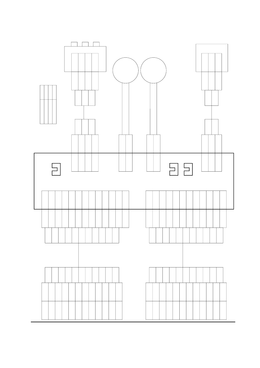
Wiring diagram ....................................................................................................................................... A-3
A-3
PF-60
BE
BE
BE
BE
BE
BE
BE
BE
BE
BE
BE
BE
+24 V
+5 V
SCLK
SDO
SDI
READY
GND
PFSEL
SEL0
SEL1
SEL2
GND
CN8-1
CN8-2
CN8-3
CN8-4
CN8-5
CN8-6
CN8-7
CN8-8
CN8-9
CN8-10
CN8-11
CN8-12
CN2-1
CN2-2
CN2-3
CN2-4
CN2-5
CN2-6
CN2-7
CN2-8
CN2-9
CN2-10
CN2-11
CN2-12
CN2-13
+24 V
READY
SDO
SCLK
SDI
SEL0
SEL1
SEL2
GND
PFSEL
+5 V
GND
N.C
1
!
4
3
5
2
@
0
6
7
8
9
BE
BE
BE
BE
BE
BE
RD
BE
BE
BE
BE
BE
PSSW0
SGND
PSSW1
PSSW2
CN4-1
CN4-2
CN4-3
CN4-4
CN10-1
CN10-2
CN10-3
CN10-4
PSSW0
SGND
PSSW1
PSSW2
+24 V
PFCL
CN1-1
CN1-2
1
2
3
4
1
2
3
4
BE
BE
BE
BE
BE
BE
BE
BE
BE
BE
BE
BE
1
2
3
4
5
6
7
8
9
0
!
@
INTERFACE IN
BN
BN
BN
BN
BN
BN
BN
BN
BN
BN
BN
BN
+24 V
+5 V
SCKD
SDO
SDI
READY
GND
PFSEL
SEL0
SEL1
SEL2
GND
CN9-1
CN9-2
CN9-3
CN9-4
CN9-5
CN9-6
CN9-7
CN9-8
CN9-9
CN9-10
CN9-11
CN9-12
CN3-1
CN3-2
CN3-3
CN3-4
CN3-5
CN3-6
CN3-7
CN3-8
CN3-9
CN3-10
CN3-11
CN3-12
+24 V
READY
SDO
SCKD
SDI
SEL0
SEL1
SEL2
GND
PFSEL
+5 V
GND
1
!
4
3
5
2
@
0
6
7
8
9
BN
BN
BN
BN
BN
BN
BN
BN
BN
BN
BN
BN
1
2
3
4
5
6
7
8
9
0
!
@
INTERFACE OUT
Paper feeder board
Paper size switch
Paper feed
sensor
Paper gauge sensor 1, 2
Motor clock sensor
Paper feed
clutch
Paper feed
motor
PFCL
PFM2
PFM1
CN7-1
CN7-2
PFM
BE
BE
BE
BE
BE
BE
SGND
MCS
+5 V
CN6-1
CN6-2
CN6-3
CN12-1
CN12-2
CN12-3
+5 V
MCS
SGND
1
2
3
3
2
1
Wire color
Brown
Blue
Red
Mark
BN
BE
RD
Wiring diagram
Document Outline
- Cover
- Chapter 1 P r o d u c t I n f o r m a t i o n
- Chapter 2 I n s t a l l a t i o n
- Chapter 3 M a i n t e n a n c e
- Chapter 4 O p e r a t i o n O v e r v i e w
- Chapter 5 D i s a s s e m b l y
- Chapter 6 T r o u b l e s h o o t i n g
- Chapter 7 P a p e r S p e c i f i c a t i o n s
- Appendix A D i a g r a m s
Wyszukiwarka
Podobne podstrony:
Kyocera Paper Feeder PF 60 Parts Manual
Kyocera Paper Feeder PF 60 Parts Manual
Kyocera Paper Feeder PF 34 Parts Manual
Kyocera Paper Feeder PF 30 Parts Manual
Kyocera Paper Feeder PF 25 Parts Manual
Kyocera Paper Feeder PF 20 Parts Manual
Kyocera Paper Feeder PF 16 Parts Manual
Kyocera Paper Feeder PF 7e Parts Manual
Kyocera Paper Feeder PF 1 Parts Manual
Kyocera Paper Feeder PF 5 Parts Manual
Kyocera Paper Feeder PF 8 Parts Manual
Kyocera Paper Feeder PF 2 Parts Manual
więcej podobnych podstron