
Power Conversion Topic: 4.
POWER CONVERSION SYSTEMS DC-DC; AC-DC; AC-AC; UPS
Control of a single phase three level voltage source inverter for
grid connected photovoltaic systems
Hinz H.
*
, Mutschler P.
*
, Calais M.
**
*
Darmstadt University of Technology, Institute for Power Electronics and Drives
Landgraf-Georg Straße 4 D-64283 Darmstadt Tel.:+49-6151-162166 Fax:+49-6151-162613
Email: hhinz@srt.tu-darmstadt.de
pmu@srt.tu-darmstadt.de
**
Curtin University of Technology, Centre for Renewable Energy Systems Technology
Australia (CRESTA), GPO Box U 1987, Perth 6845, Western Australia
Email: pcalaism@cc.curtin.edu.au
Abstract:
An improved approach for grid connected photovoltaic systems is the application of inverter
without transformers. The single phase three level half bridge is a reasonable solution for
systems in the lower power range. To achieve a steady state operation the control of the dc-
side (solar array) and the ac-side (utility grid) is required. This paper describes the control
strategy of the transformerless photovoltaic inverter.
The maximum available power of the solar modules depends on insolation and temperature. To
operate the system at the maximum power point, a suited tracking method is applied. This
method depends on the fact, that in a single phase system the instant power oscillates with
twice the line frequency. This oscillation in ac-power also leads to a 100 Hz ripple in the dc-
voltage and dc-power. The maximum power tracking is based on the analyses of the phase
relationship between the oscillation in the dc-voltage and dc-power.
To supply a sinusoidal line current with low distortion the connection of the inverter to the
utility grid is made via an ac-filter which consists of an L-C-L combination. For the inverter
output current a hysteresis controller with a variable hysteresis width is used. Additionally the
state variables of the filter are fed back by a superimposed state variable controller to achieve
an actively damped filter.
The final paper explains the control method and discusses simulation and experimental results.
Introduction
As state of the art, most commercial inverters
for grid connected photovoltaic systems include
a transformer and several sections of power
conversion [1]. To improve existing systems it is
proposed to omit the transformer and to use only
one section of power conversion.
Using transformerless inverters for the grid
connection, parasitic capacitance between solar
array and ground can lead to oscillations of the
array voltage and leakage current. This impairs
the system performance; leakage currents distort
the line current and array voltages exceed
permissible levels. The influence of the
capacitance can be eliminated, if the mid-point
of the dc-link can be connected to the ground.
For that reason the three level half bridge is a
reasonable solution for the transformerless grid
connection, since in the three level inverter each
IGBT has to block only half of the voltage
compared to the conventional two level half
bridge.
Photovoltaic power system
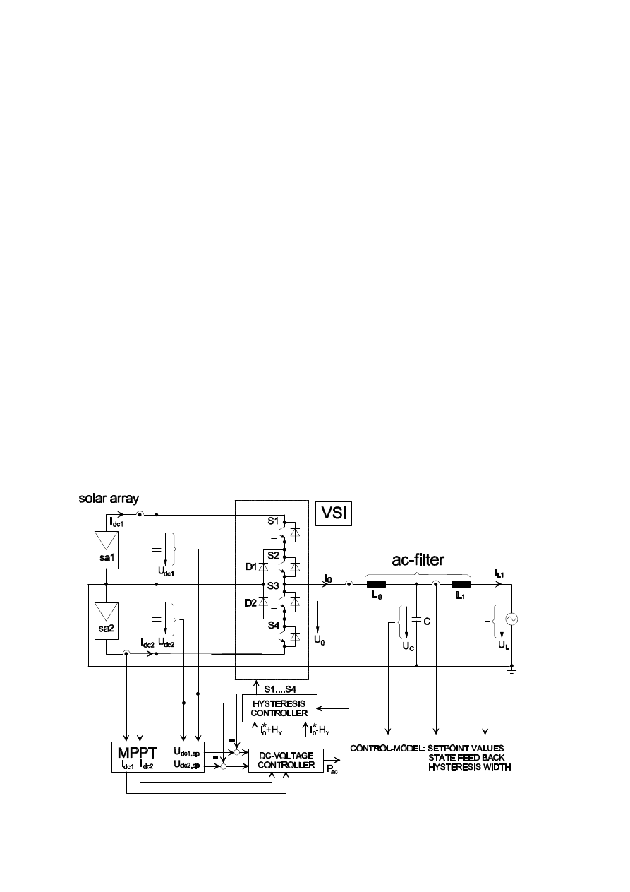
Fig. 1 shows the main structure of the
investigated photovoltaic system with a nominal
power of 2.5kW. The solar arrays are split into
two strings, the mid-point is connected to the
ground. The three level half bridge is realized by
series arranged IGBTs. The connection to the
utility grid is made by an L-C-L-filter to reduce
system perturbation.
Fig. 1 shows also the basic elements of the
control-loop block. The Maximum Power Point
Tracker (MPPT) has the duty to find the MPP
for all environmental conditions. The array
voltage is adjusted by a secondary dc-voltage
controller.
For the inverter output current a hysteresis
control is used. To damp the ac-filter actively a
superimposed state feed back controller is
applied. The setpoint values of the ac-variables
are determined suited to the available dc-power
of both arrays (P
dc1
+ P
dc2
=P
ac
).
MPPT and dc-voltage control
The output power P
dc
of the solar arrays varies
with the temperature
ϑ
and insolation E as
shown in Fig. 2 (power voltage characteristics of
one solar array with a nominal power of 1.25kW
for various temperatures and insolations); The
MPP tracking method is based on the fact, that
in a single phase system the instant power
oscillates with twice the line frequency. This
oscillation in ac-power also leads to a 100Hz
ripple in the dc-voltage and dc-power. The
maximum power point tracking uses an analyses
Fig. 1: Main structure of the photovoltaic system
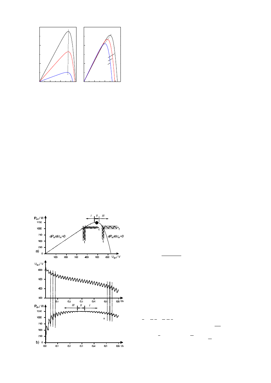
of the phase relationship between the oscillation
in the dc-voltage and dc-power to track the
MPP, as proposed in [2]. To find the MPP for
all environmental conditions, the algorithm of
the applied MPPT uses the power-voltage
gradient dP
dc
/dU
dc
of the characteristics in Fig.
3a). Operating on the left side of the MPP (area
I) the gradient is positive. This leads to an „in
phase“ condition of the array voltage U
dc1
and
power P
dc1
: the maximum of U
dc1
and P
dc1
occurs at the same time. Operating on the right
side of MPP (area III) the gradient is negative;
this leads to a phase opposition; the maximum of
U
dc1
and minimum of P
dc1
occurs at the same
time. Operating around the MPP (area II) the
ripple of the array power is minimised (Fig. 3
shows the waveforms of one array, the same
characteristics can be observed for the other
array just shifted by T
line
/2= 10ms). This
features can be used to detect in which part of
the power voltage characteristics the system
operates and which actions must be taken by the
MPPT. In the case of the voltage source inverter
operating points can be set by controlling the dc-
voltage U
dc
. The MPPT gives the set point of the
array voltage U
dc,sp
to the secondary dc-voltage
controller (see Fig. 2) which consists of a
proportional controller and a feedforward
control of the array current I
dc
. In the case of the
three level half bridge the dc-voltage of both
solar arrays must be controlled. To achieve
steady state operation the supplied dc-power of
the solar arrays and the ac-power fed into the
utility grid must be balanced. The dc-voltage
controller gives the setpoint of the ac-power to
the control model where the setpoints of the
filter-variables are determined.
The final paper will present more details of the
dc-voltage controller and MPPT as well as
simulation results.
Current control and state feed back
To supply a sinusoidal line current the
connection to the utility grid is made via an L-C-
L-filter.
For the inverter output current a hysteresis
control is used. Good results are obtained by
using an almost constant switching frequency.
This can be easily achieved by an open loop
control of the hysteresis width, which dependes
on the dc-link voltage U
dc
and filter-capacitor
voltage u
C
, the inverter-side filter inductor L
0
and the required value of the switching
frequency f
S
:
H
y
= |u
C
|
U
dc
− |u
C
|
f
S
L
0
U
dc
Additionally the ac-filter is actively damped by a
superimposed control of the state variables. In
the case of the hysteresis control of i
0
the
inverter output current is impressed into the
filter. For that reason the state variables fed
back are the line current i
L1
and the filter-
capacitor voltage u
C
:
x
•
= A x
− B R x
with
x =
i
L1
u
C
A =
0
1
L
1
−
1
C
0
Fig. 3: Principle of the MPPT
0
200
400
600
0
500
1000
1500
U
sa
/V
U
sa
/V
P/W
ϑ
=0°C = const.
E=200W/m
2
E=600W/m
2
E=1000W/m
2
MPP
0
200
400
600
0
500
1000
1500
ϑ
=20°C
ϑ
=40°C
ϑ
=60°C
E=1000W/m
2
= const.
MPP
Fig. 2: Power-voltage characterisitcs
B =
0
1
C
R =
(
)
r
L
r
C
The controller matrix R can be determined by
the selection of the poles; using a real double
pole the solution of the characteristic
polynominal will give equations for the
coefficients of the state feedback:
det[ sI
− ( A − B R ) ] =( s − λ
12
)
2
⇒
⇒
r
C
=
− λ
12
2 C
r
L
=
λ
2
12
L
1
C
− 1
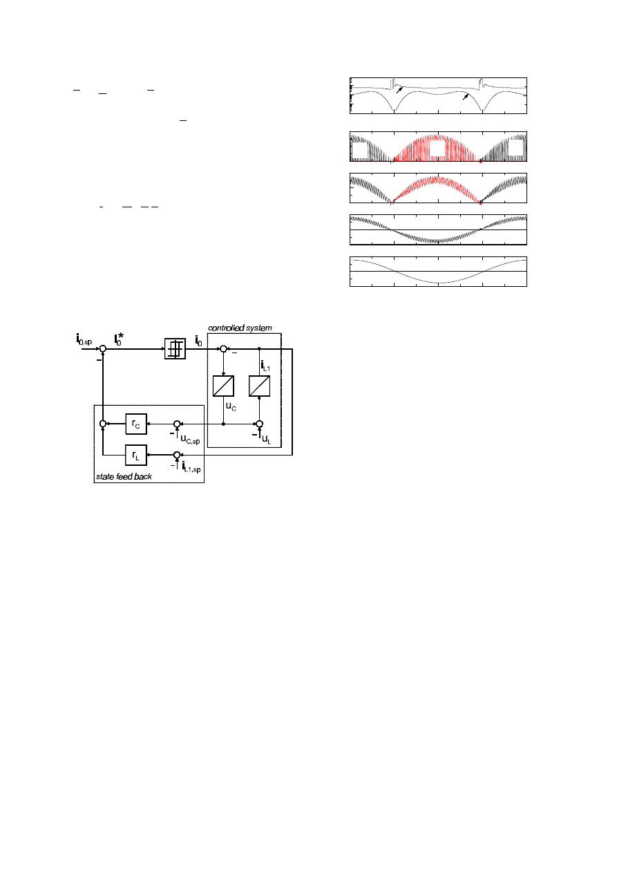
Fig. 4 shows the block diagram of the state feed
back with the secondary hysteresis control of the
inverter output current i
0
. Under steady state
conditions the state controller expects constant
values of the state variables; in the case of the
filter they are sinusoidal. For that reason the
setpoint values of the filter-capacitor voltage
u
C,sp
and the line current i
L1,sp
are subtracted.
Fig. 5 shows simulation results of the inverter
operating at the nominal power point of 2.5kW .
The switching frequency was set to f
S
= 6kHz
the filter elements to L
0
= 4mH, L
1
= 3.1mH and
C = 23
µF , these parameters are the results of
an optimising procedure described in [3] at
which the efficiency of the inverter can be
maximised. Fig. 5 shows the instantaneous
switching frequency f
S
and hysteresis width H
Y
,
the out and inner IGBT currents (I
S1
, I
S4
and I
S2
,
I
S3
) the hysteresis controlled inverter output
current I
0
and the sinusoidal line current I
L1
. In
the shown situation the fundamental waves of
the inverter output I
0
current and voltage U
0
are
controlled to be in phase, so that the two inner
IGBTs are only switched at the fundamental
frequency. By this strategy inverter losses can be
reduced.
In the final paper the current control will be
presented in detail as well as the practical
realisation and experimental results.
Conclusion
For grid connected photovoltaic systems the
control of a single phase three level inverter
without transformer has been presented. A
maximum power point tracker in combination
with a dc-voltage controller has been developed
to operate the system at the MPP for all
environmental conditions. A sinusoidal line
current can be supplied by using a hysteresis
controller which operates with an almost
constant switching frequency. The ac-filter is
actively damped by a superimposed state
controller.
Literature
[1] Steigerwald, R. et. al.: Investigations of a family
of power conditioners into utility grid, SAND, 81-
7031, 1981
[2] Avril, J.: Untersuchungen zur Betriebs-
optimierung eines einphasigen Pulswechselrichters
für Photovoltaikanlagen im Netzparallelbetrieb,
Thesis Hagen 1994
[3] Hinz, H.: How to choose switching frequency
and filter elements for a maximum efficiency
photovoltaic inverter, PCIM 1997 pp 429-438
Fig. 4: Block diagram of the state fed back
-20A
0A
20A
0
T
line
/2
T
line
=20ms
line current I
L1
-20A
0A
20A
inverter output current I
0
0A
10A
20A
I
S2
I
S3
I
S2
0A
10A
20A
I
S1
I
S4
I
S1
instantaneous switching frequency and hysteresis width
inner IGBT currents
outer IGBT currents
0,1kHz
10kHz
1kHz
f
s
H
y
0A
2A
4A
Fig. 5: Simulation results
Wyszukiwarka
Podobne podstrony:
A Composite Pwm Method Of Three Phase Voltage Source Inverter For High Power Applications
A Composite Pwm Method Of Three Phase Voltage Source Inverter For High Power Applications
A neural network based space vector PWM controller for a three level voltage fed inverter induction
A PIC CONTROLLER FOR GRID CONNECTED PV SYSTEM USING A FPGA BASED INVERTER
Algebraic PWM Strategies of a Five Level NYC Voltage Source Inverter
A Simplified Functional Simulation Model for Three Phase Voltage Source Inverter Using Switching Fun
Algebraic PWM Strategies of a Five Level NYC Voltage Source Inverter
Single Phase Line Frequency Commutated Voltage Source Inverter Suitable for fuel cell interfacing
An Active Power Filter Implemented With A Three Level Npc Voltage Source Inverter
A Series Active Power Filter Based on a Sinusoidal Current Controlled Voltage Source Inverter
A Series Active Power Filter Based on Sinusoidal Current Controlled Voltage Source Inverter
Development Of A Single Phase Inverter For Small Wind Turbine
A Series Active Power Filter Based on Sinusoidal Current Controlled Voltage Source Inverter
MODELLING GRID CONNECTED VOLTAGE SOURCE INVERTER OPERATION
The Discrete Time Control of a Three Phase 4 Wire PWM Inverter with Variable DC Link Voltage and Bat
The Discrete Time Control of a Three Phase 4 Wire PWM Inverter with Variable DC Link Voltage and Bat
więcej podobnych podstron