Fitting Instructions / Inbouwinstructie / Manuel d’ Instruction
Fitting Instructions / Inbouwinstructie / Manuel d’ Instruction
683706*0
1/ 11
SGi
SGi
13-11-2000
Instruction number / Instructienummer / Numero d’instruction:683706 * 0
Car type / Auto type / Automobile type:
Peugeot 406 2.2 16V
Year of construction / Bouwjaar / Année de fabrication
‘00
Engine code / Motorcode / Numero du moteur:
3FZ
Injection system / Injectiesysteem / Injection systeme:
MMBA
Kitnumbers / Setnummers / Numeros du set:
693706
(GB)
These fitting instructions only contain specific information about this type of car. For further information always
refer to the “AG Dealer Information” binder.
Always check the system for leakage after filling up the LPG tank.
All electrical connections must be made with the supplied connectors or be soldered and finished with heatshrink.
The given measures and threadcolors in this instruction, should always be checked and measured in case of
occurring changes in the cars wiring and possible changes in type of vehicle.
The measures used in this manual are, if not mentioned specificly, given in mm’s.
Always use an anti-corrosion coating where necessary to prevent rust.
In case a caravan coupling will be fitted, AG advises to mount this before fitting the LPG tank.
(NL)
Deze inbouwinstructie vermeldt alleen de specifieke informatie voor dit type auto. Voor verdere informatie moet
altijd de “Dealer informatie map” geraadpleegd worden.
Controleer na het tanken de gehele installatie op eventuele lekkage.
Electrische verbindingen moeten gemaakt worden met de daarvoor bijgeleverde connectoren of d.m.v. solderen
en afwerken met krimpkous.
De in deze instructie aangegeven maten en draadkleuren dienen zelf opgemeten en gecontroleerd te worden
i.v.m. onderlinge verschillen in de auto’s en mogelijke wijzigingen in de bedrading.
De in deze instructie gebruikte maten worden, indien niet nader vermeld, weergegeven in mm’s.
Behandel na de inbouw de door de inbouw ontstane korrosiegevoelige plaatsen altijd met een korrosiewerend
middel. AG adviseert om een eventuele trekhaak te monteren alvorens de LPG tank wordt geplaatst.
(FR)
Cette manuel d’instruction signale uniquement les informations spécifiques pour ce type de voiture. Pour dáutres
informations, il faudrait systématiquement consulter le “classeur Dealer-information”.
Après avoir fait le plein, contrôlez toute l'installation en vue d'une fuite éventuelle à l'aide d'une bombe de recherche
de fuite ou d'un détecteur de gaz.
Les connections électriques devraient être réalisées avec les connecteurs fournis ou à l'aide de soudures et ter-
minées avec gaine rétractable.
Les mesures et couleurs des fils indiqués dans cette instruction sont à mesurer ou contrôler par soi-même en rai-
son des variations entre les différentes voitures et des possibles modifications des câblages.
Traitez tous les trous de perçage avec un antirouille.
Toutes les dimensions sont données en milimètres sauf indication contraire.
Fitting Instructions / Inbouwinstructie / Manuel d’ Instruction
Fitting Instructions / Inbouwinstructie / Manuel d’ Instruction
683706*0
2/ 11
SGi
SGi
13-11-2000
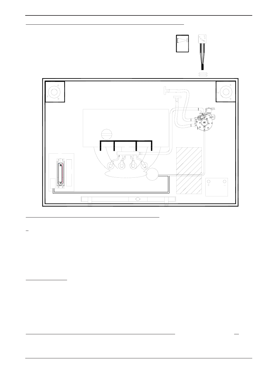
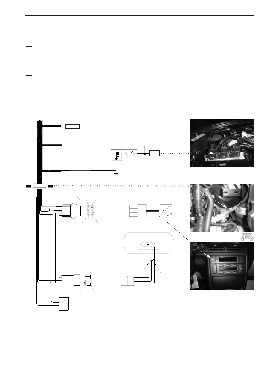
LPG switch
Overview system / Systeem overzicht / Implantation Générale
Fitting order / Montage volgorde / Ordre de montage
Nr.:
Description / Omschrijving / Description:
Page / Bladzijde / Feuille :
1.
Vaporiser / Verdamper / Vaporiseur
3
2.
Waterconnections / Wateraansluitingen / Connections d` eau
3
3.
Vacuumnipple / Vacuümnippel / Nipple à dépression
4
4.
SGI-injectors / SGI-injectoren / Injecteurs SGI
4
5.
Fuel rail LPG / Fuel rail LPG / Common rail GPL
5
6.
Interface unit / Interface unit / Unit d’ interface
5
7.
SGI-computer / SGI-computer / Calculateur SGI
6
8.
Vacuumhoseconnections / Vacuümslangaansluitingen / Connections de tuyau à dépression
6
9 , 10 , 11 , 13 + 14 :
Mount connectors to the components / Monteer connectoren op de componenten /
Monter les connecteurs aux composants
8
12.
Petrol injector interruptions / Benzine injector onderbrekingen / Coupure injecteurs d’ essence
8
15.
Temperature signal / Temperatuur signaal / Signal de temperature
9
16.
Ground / Massa / Masse
9
17.
Grummet / Doorvoerrubber / Passe fil caoutchouc
9
18.
Connections to LPG switch / Aansluitingen LPG schakelaar / Connections vers l’ interrupteur
9
19.
Switch / Schakelaar / Interrupteur
9
20.
Beeper / Alarm / Alarme sonore
9
Explanation of symbols / Beschrijving symbolen / Définition symboles
10
15
1
2
3
4
5
6
7
8
12
18
19
20
17
Fitting Instructions / Inbouwinstructie / Manuel d’ Instruction
Fitting Instructions / Inbouwinstructie / Manuel d’ Instruction
683706*0
3/ 11
SGi
SGi
13-11-2000
1A
1C
2B
3A
2A
1B
T
20-16-20mm
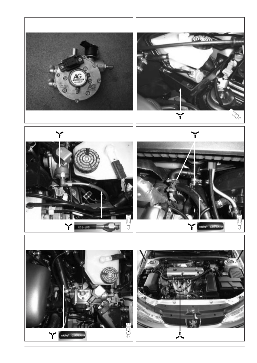
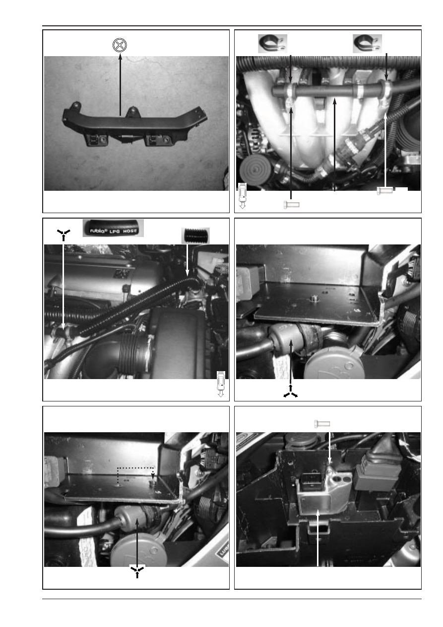
Preparation of vaporiser
Voorbereiding van verdamper
Préparation du vaporiseur
AG 2163
AG 600001
Fitting Instructions / Inbouwinstructie / Manuel d’ Instruction
Fitting Instructions / Inbouwinstructie / Manuel d’ Instruction
693706*0
4/ 11
SGi
SGi
13-11-2000
3B
4B
4D
4E
4C
4A
10
50
Ø5
Ø5
Ø9
Ø13
M6
M14x1
AG 600080
23
38
38
Length/Lengte/Longueur=200 mm (2x)
Length/Lengte/Longueur=200 mm (2x)
14
14
Fitting Instructions / Inbouwinstructie / Manuel d’ Instruction
Fitting Instructions / Inbouwinstructie / Manuel d’ Instruction
693706*0
5/ 11
SGi
SGi
13-11-2000
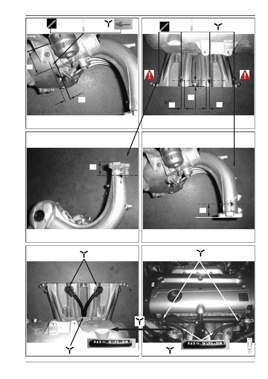
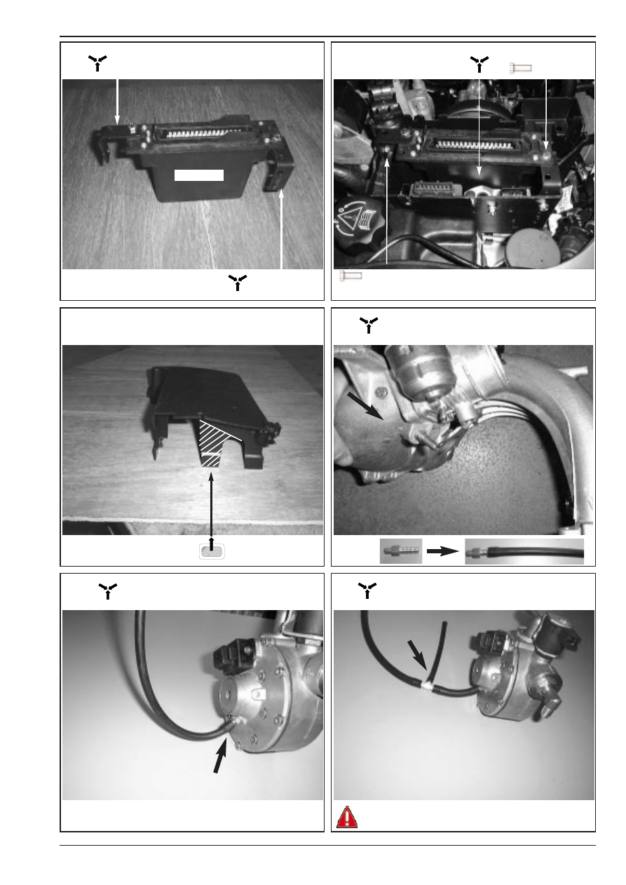
5A
5C
6B
6C
6A
5B
AG 40252
Ø 22mm
AG600190
Ø 20mm
AG600090
AG600130
M6
M6
M6
Length/Lengte/Longueur=500 mm
+
Fitting Instructions / Inbouwinstructie / Manuel d’ Instruction
Fitting Instructions / Inbouwinstructie / Manuel d’ Instruction
693706*0
6/ 11
SGi
SGi
13-11-2000
7A
7C
8B
8C
8A
7B
T
6-4-6mm
AG600100
AG202000
AG202000
M6
M6
Vacuümhose ø 5 mm
Vacuümslang ø 5 mm
Tuyau de depression ø 5 mm
Vacuümhose ø 5 mm
Vacuümslang ø 5 mm
Tuyau de depression ø 5 mm
Vacuümhose ø 3,2 mm
Vacuümslang ø 3,2 mm
Tuyau de depression ø 3.,2 mm
Mount T-part near vacuumconnection / Monteer T-stuk dichtbij vacuü-
maansluiting / Monter T-piece à coté connection à depression
+
Fitting Instructions / Inbouwinstructie / Manuel d’ Instruction
Fitting Instructions / Inbouwinstructie / Manuel d’ Instruction
693706*0
7/ 11
SGi
SGi
13-11-2000
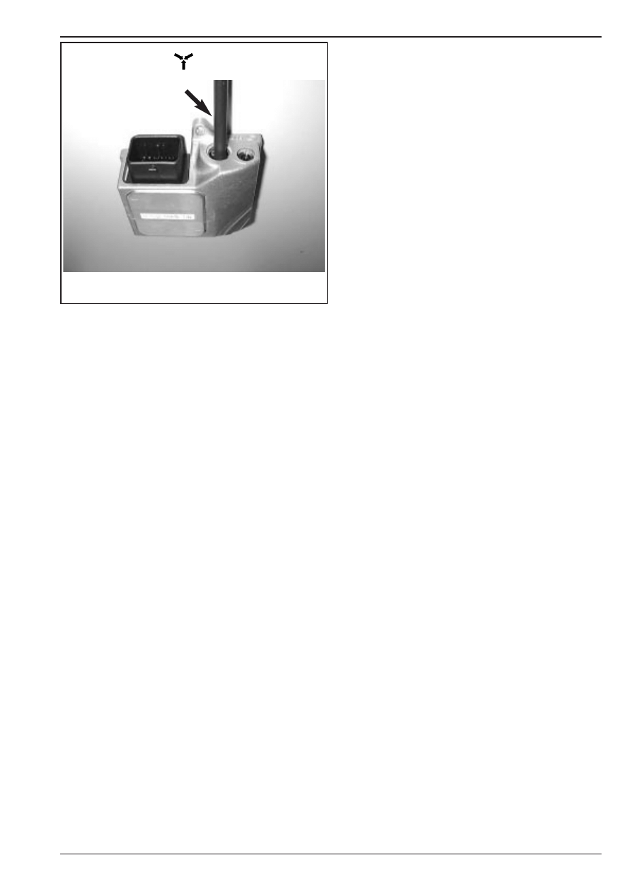
8D
Vacuümhose ø 3,2 mm
Vacuümslang ø 3,2 mm
Tuyau de depression ø 3.,2 mm
Fitting Instructions / Inbouwinstructie / Manuel d’ Instruction
Fitting Instructions / Inbouwinstructie / Manuel d’ Instruction
683706*0
8/ 11
SGi
SGi
13-11-2000
3H Red/White (+15)
Injector 2
Purple = 21
Black = 10
Injector 4
Black = 18
Purple = 34
Yellow = 31
Injector 3
Injector 2
+
-
+
-
Injector 4
Injector 3
-
+
+
-
D2 Black
C2 Black
C1 Red
E2 Black
E1 Red
D1 Red
23
6
Injector 1
19
1
5
4
3
2
21
20
22
32
Black
= 18
= 4
Brown
Red
= 2
10
9
7 8
25
24
27
26
12
14
13
11
30
28 29
31
16
15
18
17
34
33
35
Injector 1
-
+
F2 Black
F1 Red
E
1
A
B
C
D
2
3
4
H
F
G
Black 4H (GRND)
9 ,10 , 11 , 13 , + 14 :
Mount the connectors to the components
Monteer de connectors op de componenten
Monter les connecteurs aux composants
13:
Petrol injector interruptions
Benzine injector onderbrekingen
Coupure injecteurs d’essence
15 to 20 See next page
15 t/m 20 Zie volgende pagina
15 à 20 : Page suivante
DIAGNOSIS
DIAGNOSE
DIAGNOSTIC
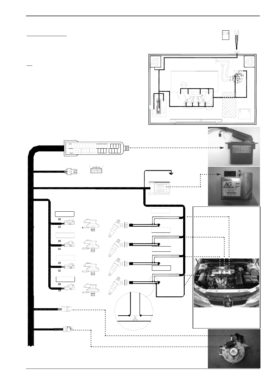
Electrical connections / Electrische aansluitingen / Raccordement électrique
LPG switch
No.1 BROWN
No.1 PURPLE
No.1 GREY
No.2 BROWN
No.1 ORANGE
9
11
13
14
12
10
Position of interruption / Plaats van onder-
breking / Position de coupures
9
11
12
14
13
15
16
17
18
20
19
9
10
Fitting Instructions / Inbouwinstructie / Manuel d’ Instruction
Fitting Instructions / Inbouwinstructie / Manuel d’ Instruction
683706*0
9/ 11
SGi
SGi
13-11-2000
Black/White = 24
Black = 18
GRND - (31)
4.
6.
5.
5.
4.
6.
4. Black = 18 GRND -
7. Blue = 17 Beeper
5. Purple = 34 LPG+
6. Yellow Level
1. Red = 25 Contact (+15)
3. Brown = 6 Pulse
2. Orange = 1 Diagnose led
2.
3.
1.
5.
3.
1.
2.
6.
4.
Red to purple
6.
5.
Yellow to yellow
Black to black
Temperature sensor
7.
Red = 13
Black = 8
15:
Temperature sensor / Temperatuursensor / Capteur de température
16:
Ground / Massa / Masse
17:
Grummet / Doorvoerrubber / Passe fils caoutchouc
18:
Connections to LPG switch + LPG tank/Aansluitingen schakelaar+ LPG tank
Connections vers l’interrupteur GPL+ réservoir GPL
19:
LPG switch / LPG schakelaar / Interrupteur GPL
20:
Beeper / Alarm / Alarme sonore
Electrical connections / Electrische aansluitingen / Raccordement électrique
15
16
17
19
18
20
1 C
12
25
Optional
Fitting Instructions / Inbouwinstructie / Manuel d’ Instruction
Fitting Instructions / Inbouwinstructie / Manuel d’ Instruction
683706*0
10/ 11
SGi
SGi
13-11-2000
Y
16-16-16mm
T
16-16-16mm
16-20mm
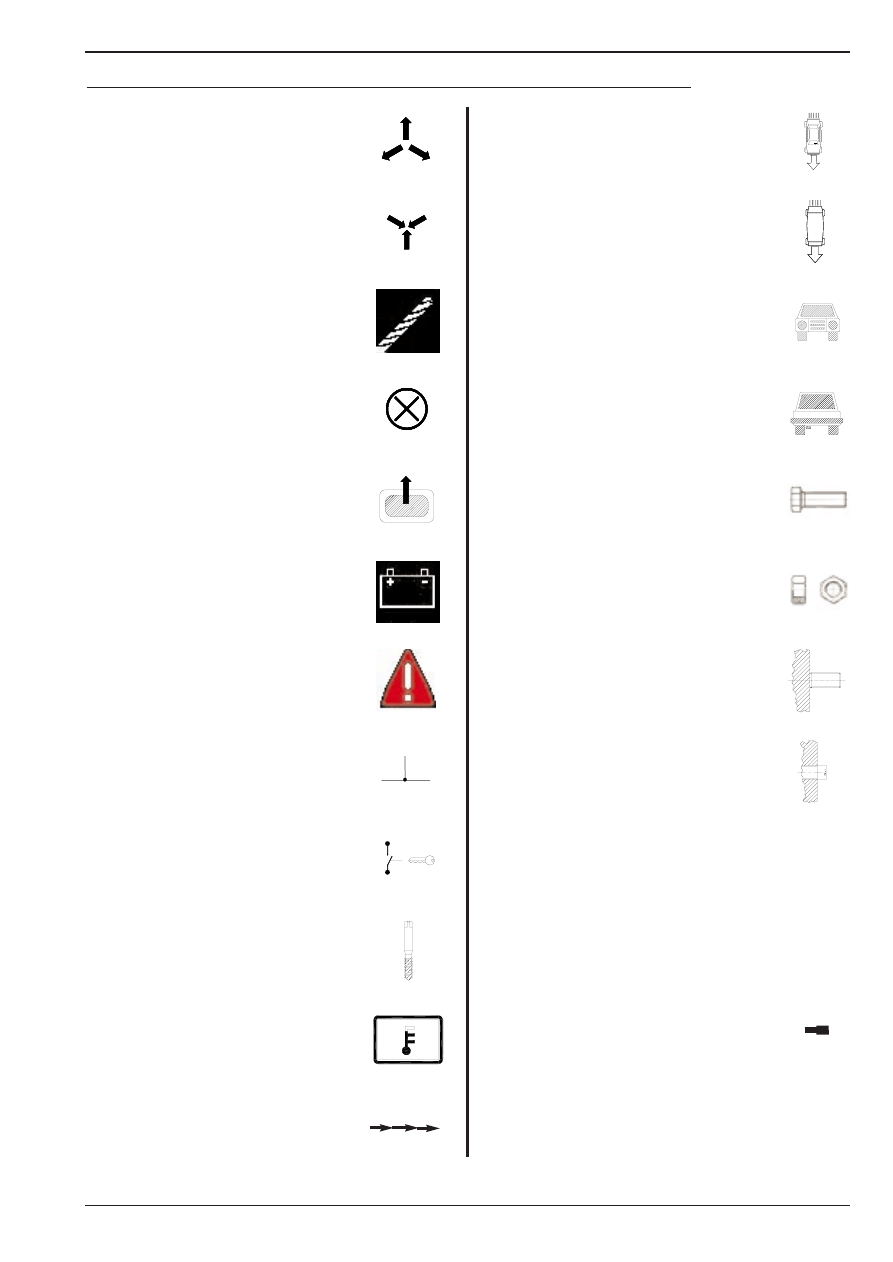
Disassemble part
Demonteer onderdeel
Démonter élément
Mount part
Monteer onderdeel
Monter élément
Drill
Boren
Percer
Redundant part
Te vervallen onderdeel
Pièce technique d’origine à supprimer
Piece to be removed from element
Te verwijderen gedeelte van onderdeel
Partie d’origine à supprimer
Battery
Accu
Batterie
Warning
Let op
Danger
Solder connection / Crimp connection
Soldeerverbinding / Krimpverbinding
Connection à souder / Connection à sertir
Ignition
Contactslot
Contact moteur
Screw tap
Draadtap
Tarauder
Temperature sensor / signal
Temperatuur sensor / signaal
Capteur / Signal de temperature
Pierce
Doorvoeren
Guider
View from top
Bovenaanzicht
Vue d’ en haut
View from bottom
Onderaanzicht
Vue d’ en bas
Frontview
Vooraanzicht
Aspect frontal
Rearview
Achteraanzicht
Aspect arrière
Bolt
Bout
Boulon
Nut
Moer
Écrou
Existing threadend
Bestaand draadeind
Boulon fileté d’origine
Existing threadhole
Bestaand draadgat
Trou taraudé d’origine
Water / Vacuum T-joint
Water / Vacuüm T-stuk
Raccord en T d’ eau / depression
Water / Vacuum Y-joint
Water / Y-stuk
Raccord en Y
Waterpipe
Waterpijpje
Raccord d’ eau
Explanation of symbols / Beschrijving symbolen / Définition symboles
Fitting Instructions / Inbouwinstructie / Manuel d’ Instruction
Fitting Instructions / Inbouwinstructie / Manuel d’ Instruction
683706*0
11/ 11
SGi
SGi
13-11-2000
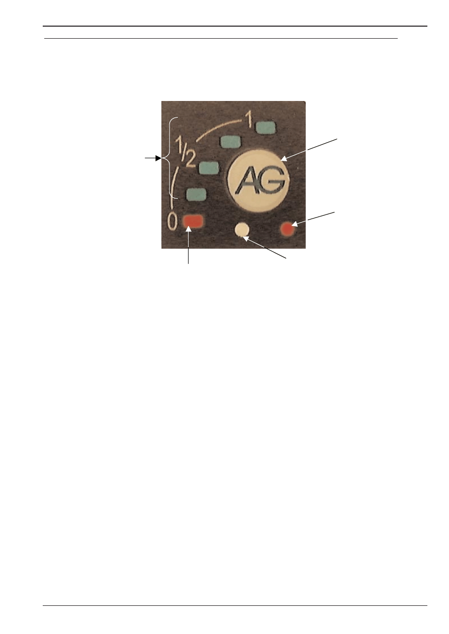
In combinatie met het Sequeniële Gas Injectie (SGI) systeem van AG Autogas Systems wordt
een puls schakelaar geleverd. Aangezien de werking van deze schakelaar verschilt van de tra-
ditionele schakelaar, vindt u hierin een beschrijving van de werking van de zgn. pulse-switch.
Op de onderstaande foto staat een afbeelding van het frontje van de pulse-switch, zoals deze
zichtbaar is op het dashboard.
Hierop is te zien, dat de schakelaar onder andere voorzien is van een aantal funkties.
A is de schakelaar zelf, waarmee overgeschakeld kan worden van LPG naar benzine. Deze
zal na het op kontakt zetten automatisch de laatst gebruikte stand aannemen. Bij lage
motortemperaturen zal de motor echter een aantal minuten op benzine draaien alvorens daad-
werkelijk overgeschakeld wordt op LPG. Hierbij worden eerst de LPG afsluiters geopend, ter-
wijl de motor nog op benzine draait (“flushen”). In deze situatie zal de tankindicatie (B en C)
tezamen met de diagnoseled (E) branden resp. knipperen. Wanneer de aanvoerslangen op
deze manier gevuld zijn met LPG, openen de SGI injectoren kort daarna, waardoor een
vloeiende overname wordt gerealiseerd. Aangezien dit een pulse-switch is, is een korte aan-
raking voldoende om over te kunnen schakelen tussen benzine en LPG.
B en C zijn de LED's, waarmee een indicatie wordt gegeven van de LPG tankinhoud. Bij een
volle LPG tank zullen alle vier de groene LED's (C) branden wanneer op LPG gereden wordt.
Gedurende het leegraken van de LPG tank zullen van boven naar beneden de LED's doven.
Bij het doven van de laatste groene LED gaat de rode LED (B) branden, als teken dat nog een
beperkte afstand op LPG afgelegd kan worden.
Indien de SGI-computer een lege tank detecteert, zal deze automatisch terugschakelen naar
benzine, hetgeen gepaard gaat met een pulserend akoestisch signaal.
D is geen indicatie, maar een fotocel, welke ervoor zorgt, dat de weergave van de indicatie
LED's B en C afhankelijk is van de lichtsterkte van de omgeving; bij zonlicht zullen de LED's
feller oplichten dan 's avonds.
E is de diagnose indicatie. Deze rode LED zal knipperen als de SGI computer de LPG stand
herkent, terwijl de motor nog op benzine draait (bijvoorbeeld bij te lage motortemperatuur of bij
een lege LPG tank (samen met een akoestisch signaal)). Indien een storing gedetecteerd
wordt tijdens het rijden op LPG, zal deze LED eveneens knipperen als teken voor de bestuur-
der om kontakt met de dealer op te nemen ten einde de storing te laten oplossen.
A
E
D
B
C
Manual AG Pulse-switch / Handleiding AG Pulse-switch / Manuel AG Pulse-switch
Wyszukiwarka
Podobne podstrony:
peugeot 406 2 0 16v '00
peugeot 306 1 6 16v '00
peugeot 206 1 6 16v 00 01
peugeot 306 1 6 16v 00
akumulator do peugeot 406 coupe 8c 20 16v 30 v6 24v
akumulator do peugeot 406 break 8ef 18 18 16v 20 16v 20 turb
akumulator do peugeot 406 8b 16 18 18 16v 20 30 24v
Peugeot 406 niestabilna temp we wnetrzu
Peugeot 406 D8 instrukcja obslugi PL by mobopx
peugeot 406 halas z klimatyzacji
Peugeot 406 D9 instrukcja obslugi PL by mobopx
Peugeot 406 nie dziala wentylator chlodnicy
peugeot 406 wentylator chlodnicy
PEUGEOT 406 02 DT
185 SC DS300 R PEUGEOT 406 A XX XX
Peugeot 406 niestabilna temp we wnetrzu
peugeot 406 wskaznik zuzucia hamulcow
Peugeot 406 D9 instrukcja obslugi PL by mobopx
więcej podobnych podstron