Fitting Instructions /Inbouwinstructie /Manuel de Montage /Manual de Instalar
Fitting Instructions /Inbouwinstructie /Manuel de Montage /Manual de Instalar SGI
683705*4
1/12
www.teleflexgfi.com
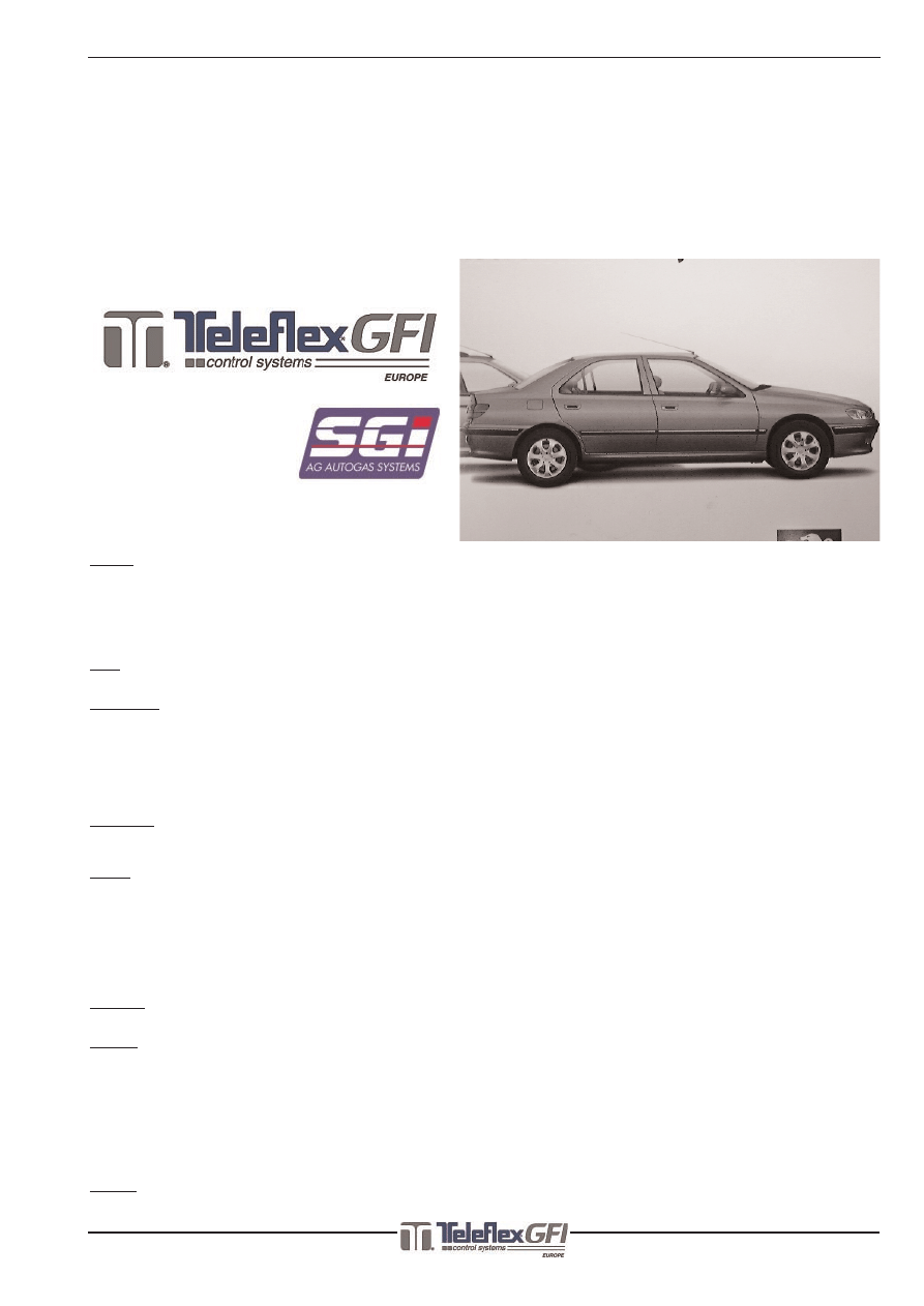
Peugeot 406 2.0 16V RFN MMBA ‘00
03-10-2003
Instruction Nr./Instructienr./No. d’instruction/No. de instrucción
:683705*4
Car type/Auto type/Automobile type/Tipo de vehiculo
:Peugeot 406 2.0 16V
Year of construction/Bouwjaar/Année de fabrication/Año de construccion :’00--->
Engine code/Motorcode/Numero du moteur/Número del motor :RFN
Injectionsystem/Injectiesysteem/Injectionsysteme/Sistema de inyeccion :MMBA
Kitnumbers/Setnummers/Numeros du set/Número del juego :693705
English
These fitting instructions only contain specific information about this type of car. For further information always refer to the “AG Dealer
Information” binder. Always check the system for leakage after filling up the LPG tank.
All electrical connections must be made with the supplied connectors or be soldered and finished with heatshrink.
The given measures and threadcolors in this instruction, should always be checked and measured in case of occurring changes in the cars
wiring and possible changes in type of vehicle. The measures used in this manual are, if not mentioned specificly, given in mm’s.
Always use an anti-corrosion coating where necessary to prevent rust.
Note: This manual is based on Dutch regulations. It is the installer’s responsibility to check the local regulations and to make all neccesary
adaptions ! AG recommends to check this instruction through the website WWW.TELEFLEXGFI.COM on eventual updates !
Nederlands
Deze inbouwinstructie vermeldt alleen de specifieke informatie voor dit type auto. Voor verdere informatie moet altijd de “Dealer informatie
map” geraadpleegd worden. Controleer na het tanken de gehele installatie op eventuele lekkage.
Electrische verbindingen moeten gemaakt worden met de daarvoor bijgeleverde connectoren of d.m.v. solderen en afwerken met krimpkous.
De in deze instructie aangegeven maten en draadkleuren dienen zelf opgemeten en gecontroleerd te worden i.v.m. onderlinge verschillen in
de auto’s en mogelijke wijzigingen in de bedrading.
De in deze instructie gebruikte maten worden, indien niet nader vermeld, weergegeven in mm’s.
Behandel na de inbouw de door de inbouw ontstane korrosiegevoelige plaatsen altijd met een korrosiewerend middel.
Opmerking:Deze instructie is gebaseerd op de Nederlandse inbouweisen.Het is de verantwoordelijkheid van de inbouwer om de lokale regels
te controleren en alle nodige aanpassingen uit te voeren! AG adviseert om via de website WWW.TELEFLEXGFI.COM eventuele updates op
deze instructie te controleren !
France
Cette manuel d’instruction signale uniquement les informations spécifiques pour ce type de voiture. Pour dáutres informations, il faudrait sys-
tématiquement consulter le “classeur Dealer-information”.
Après avoir fait le plein, contrôlez toute l'installation en vue d'une fuite éventuelle à l'aide d'une bombe de recherche de fuite ou d'un détecteur
de gaz.
Les connections électriques devraient être réalisées avec les connecteurs fournis ou à l'aide de soudures et terminées avec gaine rétractable.
Les mesures et couleurs des fils indiqués dans cette instruction sont à mesurer ou contrôler par soi-même en raison des variations entre les dif-
férentes voitures et des possibles modifications des câblages. Traitez tous les trous de perçage avec un antirouille.
Toutes les dimensions sont données en milimètres sauf indication contraire.
Attention:Cette manuel d’instruction ets bassé sur normes néerlandais. C’est la responsabilité du mechanicien pour controller les normes locale-
ment !AG conseils à controller des modifications des instructions dans WWW.TELEFLEXGFI.COM !.
Español
Estas instrucciones de montaje solamente indican la información específica para este tipo de vehículo. Con respecto al resto de la información
deberá consultar siempre el libro de las ‘’instrucciones para el concesionario’’.
Controle siempre, después de haber ilenado el tanque, toda la instalación de eventuales goteos.
Las conexiones eléctricas deben ser realizadas con las conexiones suministradas para tal fin o mediante la soldadura y su terminación con una
mazarota ajustada en caliente.
Las dimensiones y los colores de cables indicados en el presente manual deben ser medidos y controlados por Ud. mismo, debido a los posi-
bles cambios en los vehículos y las posibles modificaciones del cableado.
Las dimensiones indicadas en el presente manual son, si no hay otro tipo de indicación, siempre en milímetros.
Después de la instalación, trate los lugares sensibles a la corrosión, debido a la misma instalación, con una sustancia anticorrosión.
Atención : Las instaladores haber las deber para las reglas tópico en comprobar y todas las adaptiones necariamente en hacer !
AG encontrar que la recomendable esta manual para controlar a WWW.TELEFLEXGFI.COM en relación con modificaciónes !
Fitting Instructions /Inbouwinstructie /Manuel de Montage /Manual de Instalar
Fitting Instructions /Inbouwinstructie /Manuel de Montage /Manual de Instalar SGI
683705*4
2/12
www.teleflexgfi.com
Peugeot 406 2.0 16V RFN MMBA ‘00
03-10-2003
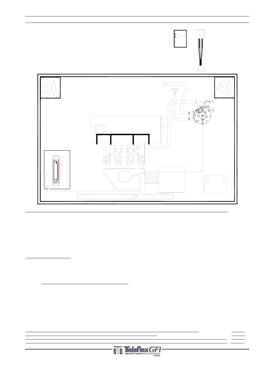
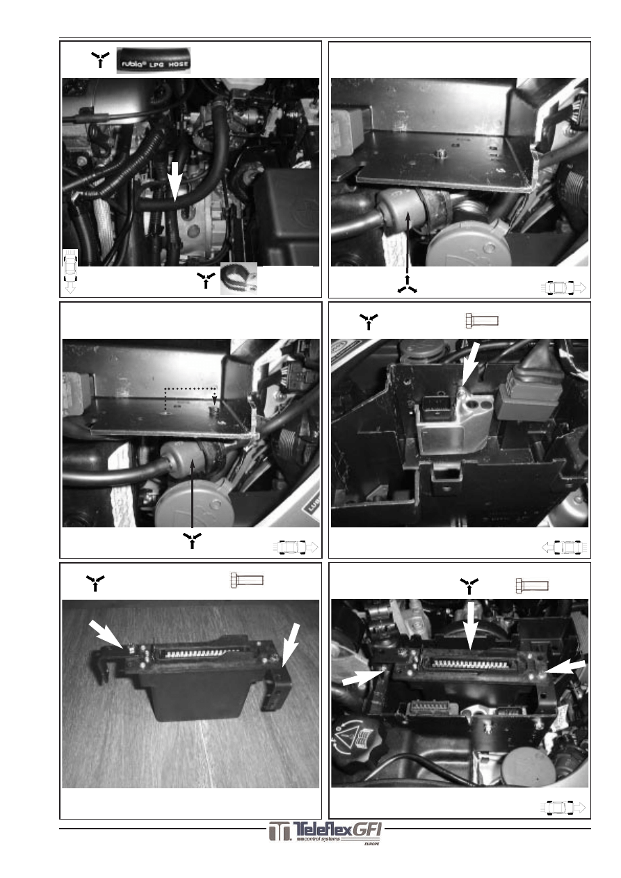
OverviewSystem/SysteemOverzicht/ImplantationGénérale/Resumen del Sistema
Fitting order / Montage volgorde / Ordre de montage / Orden de montaje
1.
Vaporiser / Verdamper / Vaporiseur / Vaporizador
2.
Waterconnections / Wateraansluitingen / Connections d` eau / Connexiones de agua
3.0
Vacuumnipple / Vacuümnippel / Nipple à dépression/ Vacio conexione
3.1
SGI-injectors / SGI-injectoren / Injecteurs SGI / Inyectores SGI
3.2
Fuel rail LPG / Fuel rail LPG / Common rail GPL/ Rail de combustible de gas
4.
Interface unit / Interface unit / Unit d’ interface / Unidad de interfaz
5.
SGI-computer / SGI-computer / Calculateur SGI / Ordenador SGI
6.
Vacuumhoseconnections/Vacuüm sl.aansluitingen/Connections de tuyau à dépression/Manga de vacío
7 , 8 , 9 , 10 + 11 :
Mount connectors to the components / Monteer connectoren op de componenten /
Monter les connecteurs aux composants / Montar las connectores en los componentes
12.
Petrol injector interruptions /Benzine injector onderbrekingen /Interruption injecteurs d’ essence /
Interrupción de inyectores de la gasolina
Remark / Opmerking / Remarque / Observación :
Cylinderarrangement according to data carmanufacturer /Cilindernummering gelijk aan data autofabrikant
Numérotage cylindres égal données fabricant de auto / Numeración cilindros igual datos fabricante de coche
13.
Temperature signal / Temperatuur signaal / Signal de temperature /Señal de la temperatura
14.
Ground / Massa / Masse/ Tierra
15.
Grummet / Doorvoerrubber / Passe fil caoutchouc / Pasador coucho
16.
Switch / Schakelaar / Interrupteur / Interruptor
17.
Connections to LPG switch/Aansluitingen LPG schakelaar /Connections vers l’ interrupteur/Conexiones al interruptor
18.
Beeper /Alarm /Alarme /Alarma
19.
Petrol indicator interruption / Benzinemeter onderbreking / Coupure indicateur d’essence /
Interrupción indicación gasolina
Explanation of symbols / Beschrijving symbolen / Définition symboles/ Explicacíon de los símbolos
Page 10
Legend various / Legenda diversen / Légende divers / Leyenda miscelánea
Page 10
Manual AG Pulse-switch/Handleiding AG Pulse-switch/Manuel AG Pulse-switch/Manual de interruptor de pulsación
Page 11
Supplement towards driver /Bijlage voor de bestuurder /Supplément pour l’utilisateur /Anejo a favor de conductor Page 12
LPG switch
15
1
2
3.1
3.0
4
3.2
6
6
6
5
16
18
12
14
17
13
Fitting Instructions /Inbouwinstructie /Manuel de Montage /Manual de Instalar
Fitting Instructions /Inbouwinstructie /Manuel de Montage /Manual de Instalar SGI
683705*4
www.teleflexgfi.com
03-10-2003
3/12
Peugeot 406 2.0 16V RFN MMBA ‘00
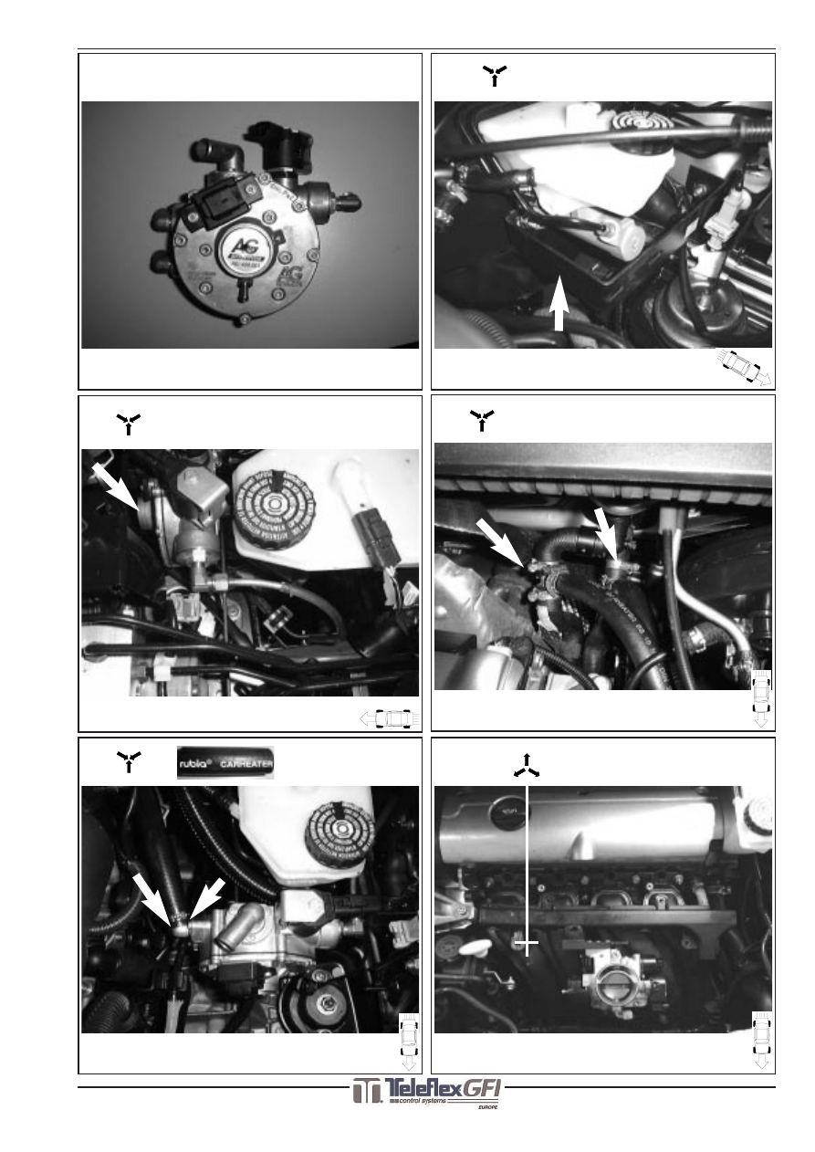
1A
1C
2B
3A
2A
1B
T
20-16-20mm
AG 2163
AG 600001
2X
2X
Preparation/Voorbereiding/Préparation/Preparación
AG 600001
4/12
Peugeot 406 2.0 16V RFN MMBA ‘00
683705*4
www.teleflexgfi.com
03-10-2003
Fitting Instructions /Inbouwinstructie /Manuel de Montage /Manual de Instalar
Fitting Instructions /Inbouwinstructie /Manuel de Montage /Manual de Instalar SGI
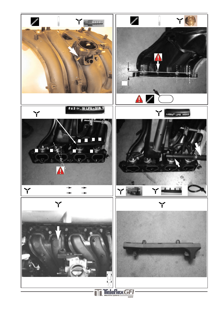
3F
3G
3C
25
3E
4 x
+
Ø 5mm
Ø 9mm
Ø 13mm
M14x1
4X
3D
AG 600090 +
AG 600050 (4x)
A
1
B
C
D
2
A
B
C
D
1
2
3
4
4
3
L =190mm(4x)
3B
M6 x 1
Ø 5mm
AG 35303
5/12
Peugeot 406 2.0 16V RFN MMBA ‘00
683705*4
www.teleflexgfi.com
03-10-2003
Fitting Instructions /Inbouwinstructie /Manuel de Montage /Manual de Instalar
Fitting Instructions /Inbouwinstructie /Manuel de Montage /Manual de Instalar SGI
3H
4C
AG600131
+
M6
AG40252
Ø 22mm
4A
4B
5B
M6
+ 2x
5A
AG 202000 +
2X
2X
M6
6/12
Peugeot 406 2.0 16V RFN MMBA ‘00
683705*4
www.teleflexgfi.com
03-10-2003
Fitting Instructions /Inbouwinstructie /Manuel de Montage /Manual de Instalar
Fitting Instructions /Inbouwinstructie /Manuel de Montage /Manual de Instalar SGI
5C
6A
6B
6C
T
6 - 4 - 6 mm
+
6D
Vacuümhose / Vacuümslang
Tuyau de depression / Manga de Vacío
Ø 3,2 mm
Vacuümhose / Vacuümslang
Tuyau de depression / Manga de Vacío
Ø 3,2 mm
Vacuümhose / Vacuümslang
Tuyau de depression / Manga de Vacío
Ø 5 mm
Vacuümhose / Vacuümslang
Tuyau de depression / Manga de Vacío
Ø 5 mm
Peugeot 406 2.0 16V RFN MMBA ‘00
www.teleflexgfi.com
Fitting Instructions /Inbouwinstructie /Manuel de Montage /Manual de Instalar
Fitting Instructions /Inbouwinstructie /Manuel de Montage /Manual de Instalar SGI
683705*4 03-10-2003
7/12
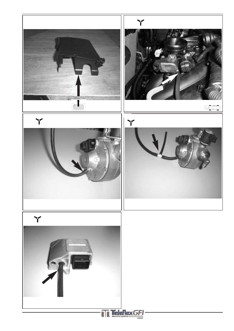
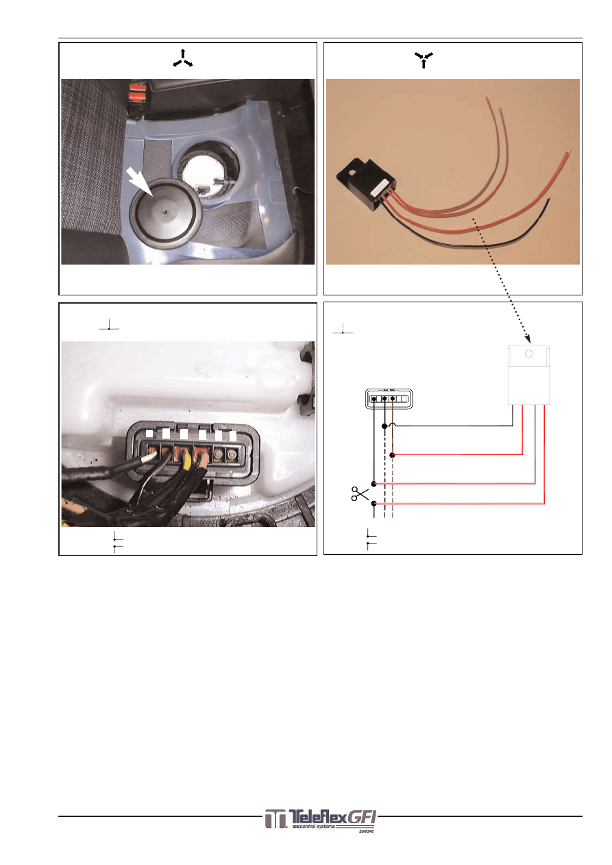
7 , 8 , 9 , 10 + 11:
Mount the connectors to the components
Monteer de connectors op de componenten
Monter les connecteurs aux composants
Montar las conectores en los componentes
12:
Petrol injector interruptions
Benzine injector onderbrekingen
Interruption injecteurs d’essence
Interrupciones del inyector de las gasolina
Remark / Opmerking / Remarque / Observación :
Cylinderarrangement equal to data carmanufacturer
Cilindernummering gelijk aan data autofabrikant
Numérotage cylindres égal données fabricant de auto
Numeración cilindros igual datos fabricante de coche
13 to 19 See next page
13 t/m 19 Zie volgende pagina
13 à 19 : Page suivante
13 hasta 19 : Véase la pagina siguiente
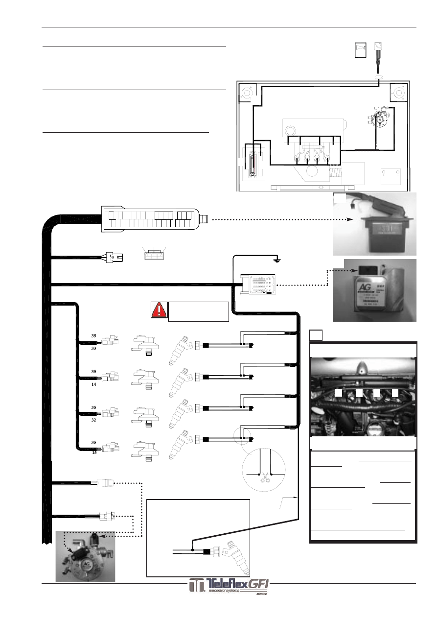
Electrical connections /Electrische aansluitingen /Raccordement électrique /Conexiones eléctricas
3H Red/White (+15)
Purple = 21
Black = 10
Connector 1
(Inj.1)
Black = 18
Purple = 34
Yellow = 31
23
6
19
1
5
4
3
2
21
20
22
32
Black
= 18
= 4
Brown
Red
= 2
10
9
7
8
25
24
27
26
12
14
13
11
30
28 29
31
16
15
18
17
34
33
35
E
1
A
B
C
D
2
3
4
H
F
G
Black 4H (GRND)
Connector 1
(Inj.1)
Connector 1
(Inj.1)
Connector 1
(Inj.1)
DIAGNOSIS
DIAGNOSE
DIAGNOSTIC
DIAGNÓSTICO
7
9
10
11
12
8
CYLINDER 1
CYLINDER 2
CYLINDER 3
CYLINDER 4
-
+
CHOICE INJECTOR ARBITRARILY
KEUZE INJECTOR WILLEKEURIG
CHOIX INJECTEUR ARBITRAIRE
ELECCIÓN INYECTOR ARBITRARIO
+
-
-
+
+
-
Interruption 1 (Inj.1)
-
+
Black
Red
Black
Red
Black
Red
Black
Red
Interruption 2 (Inj.2)
Interruption 3 (Inj.3)
Interruption 4 (Inj.4)
-
CYLINDER 1
CYLINDER 2
CYLINDER 3
CYLINDER 4
12
Cylinderarrangement / Cilindernummering
Numérotage cylindre/Numeración cilindros
Position of interruption / Plaats onderbr.
Position déconnection / Sitio interrupción
8
7
LPG switch
10
15
7
8
9
16
11
18
12
17
13
14
4
3
2
1
Power and Ground can differ at the
injectorconnector: Always interrupt the
Ground wire
Voeding en massa op de benzine-injec-
torstekker kan verschillen: Onderbreek
altijd de massa draad
Alimentation et terre aux connecteurs de
injecteurs peut différer: Coupé toujours
le câble de terre
Alimentación y tierra acaso inversa-
mente
Siempre interrupción cable de tierra !
CHECK PIN NR. 1 & 2
CONTROLEER PEN NR. 1 & 2
VÉRIFIER FICHE NR. 1 & 2
COMPROBAR ESPIGA NR. 1 & 2
Fitting Instructions /Inbouwinstructie /Manuel de Montage /Manual de Instalar
Fitting Instructions /Inbouwinstructie /Manuel de Montage /Manual de Instalar SGI
683705*4
8/12
www.teleflexgfi.com
Peugeot 406 2.0 16V RFN MMBA ‘00
03-10-2003
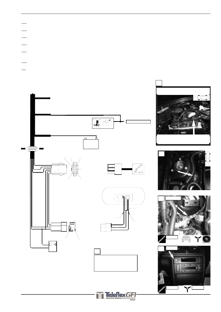
Electrical connections /Electrische aansluitingen /Raccordement électrique /Conexiones eléctricas
Position of connection / Plaats aansluiting
Position connection / Sitio empalme
13
13:
Temperature sensor / Temperatuursensor / Capteur de température / Sensor de las temperatura
14:
Ground / Massa / Masse / Tierra
15:
Grummet / Doorvoerrubber / Passe fils caoutchouc/ Pasador de caucho
16:
LPG switch / LPG schakelaar / Interrupteur GPL / Interruptor Gas
17:
Connections to LPG switch + LPG tank/ Aansluitingen schakelaar+ LPG tank /
Connections vers l’interrupteur GPL+ réservoir GPL / Conexiones al interruptor y tanque de gas
18:
Beeper/ Alarm / Alarme / Alarma
19:
Petrol indicator interruption / Benzinemeter onderbreking /
Coupure indicateur d’essence /Interrupción indicación gasolina
See next page/Zie volgende paginas/Page suivante/Véase la pagina siguiente
Position of sensor / Plaats van sensor
Position d’ détecteur / Sitio de sensor
GRND - (31)
Black = 18
1. Red = 35 Contact (+15)
7.
4.
5.
6.
7. Blue = 17 Beeper
5.
4.
6.
2.
3.
1.
4. Black = 18 GRND -
5. Purple = 34 LPG+
6. Yellow Level
3. Brown = 6 Pulse
2. Orange = 1 Diagnose led
1.
5.
2.
6.
3.
4.
+
Yellow to yellow
Red to purple
6.
5.
Black to black
-
Black/White = 24
Red = 12
Black = 25
Temperature sensor
13
14
15
16
17
18
Optional
Pinnr. E4
15
16
GRUMMET
SWITCH
SWITCH
Ø 10 MM
Ø 8 MM
14
19
See next page
Zie volgende pagina
Page suivante
Véase la pagina siguiente
Fitting Instructions /Inbouwinstructie /Manuel de Montage /Manual de Instalar
Fitting Instructions /Inbouwinstructie /Manuel de Montage /Manual de Instalar SGI
683705*4
9/12
www.teleflexgfi.com
Peugeot 406 2.0 16V RFN MMBA ‘00
03-10-2003
6
4
5
3
2
1
1
2
3
4
5
6
AG 40327
Black
Red
Red/Grey
Red/Grey
6 4
3
19d
19b
AG 40327
PinNr.6: Signalwire/Signaaldraad/
Fil de signale/Cable con señal
Split up / Aftakken/
Derivé / Deviarse PinNr. 3 + 4
Interrupt / Onderbreek/
Couper / Interrumpir PinNr. 6
19a
19c
PinNr. 3 : +12 V
Pin.Nr.4 : Ground/Massa/Masse/Tierra
Fitting Instructions /Inbouwinstructie /Manuel de Montage /Manual de Instalar
Fitting Instructions /Inbouwinstructie /Manuel de Montage /Manual de Instalar SGI
683705*4
10/12
www.teleflexgfi.com
Peugeot 406 2.0 16V RFN MMBA ‘00
03-10-2003
Y
16-16-16mm
T
16-16-16mm
16-20mm
Disassemble part
Demonteer onderdeel
Démonter élément
Desmontar la parte
Mount part
Monteer onderdeel
Monter élément
Montar la parte
Drill
Boren
Perforer
Taladrar
Redundant part
Te vervallen onderdeel
Pièce technique d’origine à supprimer
Parte a suprimir
Piece to be removed from element
Te verwijderen gedeelte van onderdeel
Partie d’origine à supprimer
Parte a quitar del elemento
Battery
Accu
Batterie
Acumulador
Cut
Knippen
Couper
Cortar
Solder connection / Crimp connection
Soldeerverbinding / Krimpverbinding
Connection à souder / Connection à sertir
Conexíon de soldeo / Conexíon de encogimiento
Scriber / Draw
Kraspen / Aftekenen
Pointe à tracer / Dessiner
Puntero de raya / Dibujar
Use screw tap
Gebruik draadtap
Faire usage de taraudeuse
Hacer uso de herramientas de rosca
Temperature sensor / signal
Temperatuur sensor / signaal
Capteur / Signal de temperature
Sensor /Señal de la temperatura
Pierce / Moving direction
Doorvoeren / Bewegingsrichting
Guider / Direction mouvement
Pasar / Dirección movimiento
Bend/Adapt
Buigen/Aanpassen
Courber/Adapter
Torcer/Adaptar
Warning
Let op
Fais attention
Advertencia
Attention for
hoses/tubes/cables
while drilling
Attentie voor
leidingen/slangen/kabels
met boren
Faites attention pour tubes/tuyau/câbles durante perforer
Advertencia
mangas/tubos/cables
durante taladrar
View from top(Indication viewpoint image)
Bovenaanzicht(Indicatie aanzicht foto)
Vue d’ en haut(Indication point de vue photo)
Visto desde arriba(Indicación punto de vista
imagen)
View from bottom(Indication viewpoint image)
Onderaanzicht(Indicatie aanzicht foto)
Vue d’ en bas(Indication point de vue photo)
Visto desde abajo(Indicación punto de vista
imagen)
Frontview(Indication viewpoint image)
Vooraanzicht(Indicatie aanzicht foto)
Aspect frontal(Indication point de vue photo)
Visto frontalmente(Indicación punto de vista
imagen)
Rearview(Indication viewpoint image)
Achteraanzicht(Indicatie aanzicht foto)
Aspect arrière(Indication point de vue photo)
Visto lateralmente(Indicación punto de vista
imagen)
Bolt
Bout
Boulon
Tornillo
Nut
Moer
Écrou
Tuerca
Existing threadend
Bestaand draadeind
Boulon fileté d’origine
Rosca existente externamente
Existing threadhole
Bestaand draadgat
Trou taraudé d’origine
Agujero de rosca existente
Water / Vacuum T-joint
Water / Vacuüm T-stuk
Raccord en T d’ eau / depression
Junta T para agua / vacío
Water / Vacuum Y-joint
Water / Y-stuk
Raccord en Y d’ eau / depression
Junta Y para agua / vacío
Waterpipe
Waterpijpje
Raccord d’ eau
Conducto de agua
Edit part
Bewerk (onder)deel
Adapter élément
Adaptar parte
Heat! Keep at least 100mm away from source
Hitte! Houd minstens100mm afstand van bron
Chaleur!Tenir
au moins
100mm
distance de source
Calor!Tenercomo mínimo 100mm distancia de fuente
Moving /Rotating parts
Bewegende / Draaiende delen
Pièces mobile / Giration
Piezas movible / Dar Vueltas
Symbols / Symbolen / Symboles / Símbolos
Various translations / Vertaling diversen / Traduction divers / Traducción diversos
English Nederlands Francais Español
GRND
Massa
Terre
Tierra
Image
Foto
Photo
Imagen
Page
Bladzijde
Page
Folio
Pin(Terminal)
Stekkerpen
Borne de fiche
Espiga de conectore
Nr.(Number) Nr.(Nummer)
No.(Numéro)
No.(Número)
Wire
Draad
Câble
Cable
Protection
Bescherming
Protection
Protección
Additional
Bijkomend
Accessoire
Adicional
Optional
Optioneel
Optionnel
Opcional
Original(Part,Bolt,e.g.) Origineel(Onderdeel,bout,bijv.) Original(Partie,Boulon p.ex.) Original(Parte,Tornillo p.ej.)
Extension(Extend)
Verleng(en)
Prolonger
Prolangar
Use
Maak gebruik van
Faire usage de
Hacer uso de
Do not use
Niet gebruiken
Non faire usage de
No usar
To (ECU e.g.)
Richting (ECU bijv.)
À (ECU p.ex.)
Para (ECU p.ej.)
Bracket
Steun
Contrefiche
Contrafuerte
Colours/Kleuren/Couleurs/Colores
English Nederlands Francais Español
White
Wit
Blanc
Blanco
Black
Zwart
Noir
Negro
Red
Rood
Rouge
Rojo
Brown
Bruin
Brun
Márron
Purple
Paars
Violet
Violeta
Yellow
Geel
Jaune
Amarillo
Orange
Oranje
Orange
Anaranjado
Blue
Blauw
Bleu
Azul
Green
Groen
Vert
Verde
Beige
Beige
Beige
Beige
Grey
Grijs
Gris Gris
Pink
Roze
Rose
Rosado
Legend various / Legenda diversen / Légende divers / Leyenda miscelánea
xx
º
100mm
(((
Fitting Instructions /Inbouwinstructie /Manuel de Montage /Manual de Instalar
Fitting Instructions /Inbouwinstructie /Manuel de Montage /Manual de Instalar SGI
683705*4
11/12
www.teleflexgfi.com
Peugeot 406 2.0 16V RFN MMBA ‘00
03-10-2003
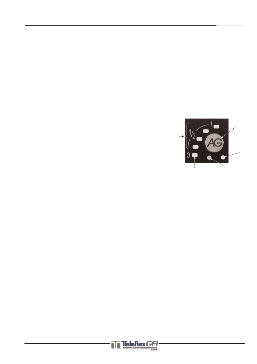
In combination with the Sequential Gas Injection (SGI) system of AG Autogas Systems a so-called pulse switch is supplied. Because the operation of
this switch differs from that of the traditional switch, a description of the pulse switch is included.
The photograph below shows the front of the pulse switch, which can be seen on the dashboard.The photograph shows that the switch is supplied
with a number of functions.
A is the switch itself. It is used to switch from LPG to petrol. When turning the ignition on the switch automatically takes the last-used position. At
low temperatures, however, the engine will run on petrol for a short time, before actually switching over to LPG. In this case the LPG shut-off valves
are opened first, with the engine still running on petrol (flushing). In this condition the tank-indicator lights (B and C) will light up or will start
flashing, together with the diagnosis LED (E). Soon after the supply lines have been filled with LPG in this way, the SGI injectors open, thus realis-
ing a smooth switch-over. Because this is a pulse switch, a light touch will do to switch over between petrol and LPG. When the car runs on petrol,
no LED will be lit or be flashing.
B and C are the LEDs that indicate the LPG level. The LEDs light up the moment the LPG shut-off valves are being fed. When the LPG tank is full, all
four green LEDs (C) will be lit (when driving on LPG). The emptier the LPG tank gets, the more LEDs will go out from top to bottom. When the last
green LED has gone out, the red LED (B) will light up, to indicate that no more than a limited distance can be driven on LPG.
When the SGI computer detects an empty tank it automatically switches over to petrol. This is indicated by a pulsating, audible signal.
D is not an indicator light, but a photocell which adjusts the display intensity of the LEDs B and C to the light intensity of the environment. During
the day, with the sun shining, the LEDs will be illuminated more brightly than in the evening.
E is the diagnosis indication. This red LED starts flashing when the SGI computer recognises the LPG position, while the car is still running on petrol
(e.g. when the engine temperatures are too low or when the LPG tank is empty (in this case together with an audible signal)). When a fault is being
detected while driving on LPG, the red LED will also start flashing as an indication for the driver to contact the dealer, who will correct the fault.
..........................................................................................................................................................................................................................................
In combinatie met het Sequentiële Gas Injectie (SGI) systeem van AG Autogas Systems wordt een puls schakelaar geleverd. Aangezien de werking
van deze schakelaar verschilt van de traditionele schakelaar, vindt u hierin een beschrijving van de werking van de zgn. pulse-switch.
Op de onderstaande foto staat een afbeelding van het frontje van de pulse-switch, zoals deze zichtbaar is op het dashboard.
Hierop is te zien dat de schakelaar onder andere voorzien is van een aantal funkties.
A is de schakelaar zelf, waarmee overgeschakeld kan worden van LPG naar benzine. Deze zal na het op kontakt zetten automatisch de laatst
gebruikte stand aannemen. Bij lage motortemperaturen zal de motor echter een aantal minuten op benzine draaien alvorens daadwerkelijk
overgeschakeld wordt op LPG. Hierbij worden eerst de LPG afsluiters geopend, terwijl de motor nog
op benzine draait (“flushen”). In deze situatie zal de tankindicatie (B en C) tezamen met de diag-
noseled (E) branden resp. knipperen. Wanneer de aanvoerslangen op deze manier gevuld zijn met
LPG, openen de SGI injectoren kort daarna, waardoor een vloeiende overname wordt gerealiseerd.
Aangezien dit een pulse-switch is, is een korte aanraking voldoende om over te schakelen tussen
benzine en LPG.
B en C zijn de LED's, waarmee een indicatie wordt gegeven van de LPG tankinhoud. Bij een volle LPG
tank zullen alle vier de groene LED's (C) branden wanneer op LPG gereden wordt. Gedurende het
leegraken van de LPG tank zullen van boven naar beneden de LED's doven. Bij het doven van de
laatste groene LED gaat de rode LED (B) branden, als teken dat nog een beperkte afstand op LPG
afgelegd kan worden.
Indien de SGI-computer een lege tank detecteert, zal deze automatisch terugschakelen naar ben-
zine, hetgeen gepaard gaat met een pulserend akoestisch signaal.
D is geen indicatie, maar een fotocel, welke ervoor zorgt, dat de weergave van de indicatie LED's B
en C afhankelijk is van de lichtsterkte van de omgeving; bij zonlicht zullen de LED's feller oplichten
dan 's avonds.
E is de diagnose indicatie. Deze rode LED zal knipperen als de SGI computer de LPG stand herkent,
terwijl de motor nog op benzine draait (bijvoorbeeld bij te lage motortemperatuur of bij een lege
LPG tank (samen met een akoestisch signaal)). Indien een storing gedetecteerd wordt tijdens het
rijden op LPG, zal deze LED eveneens knipperen als teken voor de bestuurder om kontakt met de dealer op te nemen ten einde de storing te laten
oplossen.
..........................................................................................................................................................................................................................................
Un 'interrupteur à pulsation' équipe le système d'injection séquentielle de gaz (Sequential Gas Injection, SGI) d'AG Autogas Systems. Etant donné
que le fonctionnement de cet interrupteur diffère de celui de l'interrupteur traditionnel, nous avons joint une description de cet interrupteur à pulsa-
tion.La photo ci-dessous montre l'avant de l'interrupteur à pulsation tel qu'il se présente sur le tableau de bord.
Cette photo indique que l'interrupteur dispose d'un certain nombre de fonctions.
A est l'interrupteur lui-même, utilisé pour passer du G.P.L. à l'essence. Quand on allume le contact, l'interrupteur se met automatiquement sur la
dernière position utilisée. Cependant, si le moteur est froid, il fonctionnera brièvement sur l'essence avant de passer vraiment au G.P.L. Dans ce cas,
les valves d'arrêt du G.P.L. sont d'abord ouvertes alors que le moteur fonctionne encore sur l'essence ("rinçage"). Dans cette situation, les voyants
du réservoir (B et C) ainsi que le diode électroluminescent (DEL) de diagnostique (E) s'allument ou commencent à clignoter. Une fois que les con-
duites d'alimentation sont ainsi remplies de G.P.L., les injecteurs SGI s'ouvrent, ce qui permet un passage en douceur d'un carburant à l'autre. Etant
donné qu'il s'agit d'un interrupteur à pulsation, il suffit de l'effleurer légèrement pour passer de l'essence au G.P.L. et inversement. Quand la voiture
fonctionne à l'essence, aucun voyant ne s'allume ou ne clignote.
B et C sont les DEL qui indiquent le niveau de G.P.L. Les DEL s'allument dès que les valves d'arrêt G.P.L. sont alimentées. Quand le réservoir de
G.P.L. est plein (et que le moteur fonctionne sur G.P.L.), les quatre DEL verts (C) sont allumés. Au fur et à mesure que le réservoir de G.P.L. se vide,
le nombre de DEL allumés diminue de haut en bas. Quand le dernier DEL vert s'éteint, le DEL rouge (B) s'allume pour indiquer que le G.P.L. restant
ne permet de parcourir qu'une distance limitée. Quand le système électronique SGI détecte un réservoir vide, il passe automatiquement sur le
réservoir d'essence, ce qui s'accompagne d'un signal sonore intermittent.
D n'est pas un voyant indicateur, mais une cellule photoélectrique qui règle l'intensité de l'affichage des DEL B et C sur l'intensité lumineuse
ambiante. Pendant la journée, quand le soleil brille, les DEL seront éclairés plus vivement que le soir.
E est l'indicateur de diagnostique. Ce DEL rouge commence à clignoter quand le système électronique SGI identifie la position G.P.L., alors que la
voiture fonctionne encore sur essence (par exemple quand le moteur est trop froid ou quand le réservoir G.P.L. est vide [cela s'accompagne d'un
signal sonore]). Quand une erreur est détectée alors que le moteur fonctionne sur G.P.L., le DEL rouge se met également à clignoter pour indiquer
au conducteur qu'il doit se rendre chez son concessionnaire pour remédier à ce problème.
..........................................................................................................................................................................................................................................
En combinación con el sistema de la Inyección de Gas Secuencionel (SGI) de AG Autogas Systems entregamos un interruptor de pulsación. Debido al
hecho de que el funcionamiento de este interruptor es diferente a un interuptor tradicional, le indicamos a continuación una descripción del fun-
cionamiento del tal llamado interruptor de pulsación. En la foto abajo indicada hay una ilustración de la parte frontal del interruptor de la pulsación,
tal y como es visible en el tablero de mados.
Se puede ver que el interuptor está previsto, entre otros, de una cierta candidad de funciones.
A es el mismo interuptor, con el cual se puede cambiar del gas a la gasolina. Una vez puesto en marcha el contacto, automáticamente se pone en la
última posición usada. En caso de temperaturas bajas del motor, el motor funcionará durante algunos minutos con gasolina antes de cambiar ver-
daderamente al gas. Primeramente se abren las válvulas del gas, mientras que el motor todavía funciona con gasolina (“flushen”). En esta posición,
la indicación del tanque (B y C), juntamente con el diodo electro-luminiscente (led), se ilumina y se apaga respectivamente. Cuando los conductos
de entrada sean llenados de esta manera con el gas, los inyectores de SGI se abren poco tiempo después, de modo que se realiza un paso sin inter-
ruptiones. Puesto que es un interruptor de pulsación, un ligero toque ya es suficiente para poder cambiar de la gasolina al gas.
B y C son les leds, con los cuales se da una indicación del contenido del tanque de gas. En caso de un tanque de gas lleno, todos los cuatro leds en
verde (C) están encendidos en caso de que se utiliza el gas para conducir. Cuando el tanque del gas se está vaciando, los leds se apagará desde
arriba hacia abajo. Cuando se apague el último led en verde, se enciende el led rojo (B), como señal de que solamente puede continuar conduciendo
una corta distancia más con el gas.
Si el ordenador SGI detecta en tanque vacío, éste último conectará automáticamente a la gasolina, indicando al mismo tiempo una señal pulsando
acústica.
D no es una indicación, sino una fotocélula, que hace que la reflexión de la indicación de los LED B y C dependa de la fuerza de la luz de los alrede-
dores; en caso de luz solar los leds se encienden más fuertemente que durante la noche.
E es la indicación del diagnóstico. Este led rojo destella si el ordenador de DGI reconoce la posición del gas, cuando el motor todavía funciona con
gasolina (por ejemplo en caso de una temperatura del motor demasiado baja o en caso de un tanque de gas vacío (juntamente con una señal acústi-
ca). Si se detecta una avería durante la conducción con gas, este led igualmente se enciede y se apaga para indicar al chofer que tome contacto con
el concesionario para solucionar la avería.
AG PULSE-SWITCH
Manual / Handleiding / Manuel / Manual
COPY SYSTEM
A
E
D
B
C

Fitting Instructions /Inbouwinstructie /Manuel de Montage /Manual de Instalar
Fitting Instructions /Inbouwinstructie /Manuel de Montage /Manual de Instalar SGI
683705*4
12/12
www.teleflexgfi.com
Peugeot 406 2.0 16V RFN MMBA ‘00
03-10-2003
(GB)
Dear LPG-User,
Your car has been equipped with an petrolindicator wich counts on the basis of the, by petrolcalculator, calculated fuel con-
sumtion. This has the effect that the indicator will also fall off when youre driving on LPG.
But by turning of the contact for a while, the indicator will reset. The indicator will now indicate the correct petrol stock.
This means in practice that after every start the correct petrol stock is indicated.
We trust you will understand this situation.
Kind regards,
AG AUTOGAS SYSTEMS
(NL)
Geachte bestuurder(ster),
Uw auto is uitgerust met een benzinemeter die aftelt aan de hand van het door de computer berekende brandstofverbruik.
Dit heeft als consequentie dat tijdens het rijden op LPG, de benzinemeter terug zakt. Echter na het voor enige tijd uitzetten
van het contact wordt de meter weer gereset, waarna deze de originele benzinetankinhoud weer aangeeft.
In de praktijk betekent dit dat na vrijwel iedere start de juiste (benzine)tankinhoud wordt weergegeven.
Wij vertrouwen erop dat u begrip heeft voor deze situatie.
Met vriendelijke groet,
AG AUTOGAS SYSTEMS
(FR)
A l'attention de l'utilisateur :
Madame, Monsieur,
Votre voiture est équipée d'une jauge essence électronique qui indique le niveau du carburant restant dans le réservoir par
rapport à la consommation, donnée par le calculateur essence.
Même en mode GPL, le calculateur essence continue à déduire une valeur de carburant : la jauge essence descend
Après avoir éteint le contact pendant quelques minutes, ou à chaque arrêt du véhicule, la jauge essence exécute une mise à
zéro et elle indique le contenu exact du réservoir essence.
En pratique, presque chaque fois que vous démarrerez la voiture, la jauge indique le bon contenu du réservoir essence.
Ceci ne modifie en rien la valeur, donnée par la jauge, quand vous roulez à l'essence.
Nous espérons que vous comprenez cette contrainte, indépendante de notre volonté pour cette situation.
Bien à vous,
AG AUTOGAS SYSTEMS
Wyszukiwarka
Podobne podstrony:
więcej podobnych podstron