NORPIE 2004, NTNU Trondheim Norway 14 – 16 June, 2004
Z72 Direct drive PMSG
page 1 of 7
CJAV
1
?
I. A
BSTRACT
.
Index Terms: Zephyros; wind turbine; direct drive; PM generator.
The Zephyros Z72 is a gearless variable speed wind turbine
with a direct driven PM synchronous generator with a rotor
diameter of 70 m. This article describes the design process,
testing and prototyping with focus on the generator which till
date is t he biggest PM generator available on the wind turbine
market.
The turbine after testing and commissioning has a track record
of over 8000 grid connected hours and more than 47 00 MWh
produced. Tests and operational experience is commented and
results are given. Measurements such as the power curve
(power versus average wind speed), noise and heat run have
been performed and show good results and reassembly with
the design calculations.
The turbine has been installed in April 2002 and certification
design assessment and measurements are completed.
II. I
NTRODUCTION
Zephyros b.v. (
www.zephyros.com
for more information) is a
small wind turbine manufacturer established in the
Netherlands. The company is a spin off of Lagerwey who
produces since 1994 a direct driven 750 kW wind turbine.
Zephyros has been established in 2000 to make an up scaled
design and production of a prototype possible with support of
the Dutch government and key suppliers. In order to shorten
the prototype phase it was decided to have a full scale factory
test done on generator converter system as is learned from
experience with the LW750. This has lead to the participation
of ABB in the development of generator – converter system.
As ABB designs and manufa ctures PM motors the application
of PM excitation was considered as proven technology and
adopted instead of external rotor excitation.
Manuscript submitted May 3, 2004.
C.J.A. Versteegh is senior engineer at GarradHassan & Partners and based
in the Netherlands. He has been responsible for the Zephyros Z72
design.
The address of Zephyros is: Arena business park 1, Olympia 1a/1b,
1213 NS Hilversum , Tel: +31 (0)35 6462605 , Fax: +31 (0)35
6462710, e-mail:
info@.zephyros.com
Zephyros now employs 12 persons covering the skills of
design, assembly, installation and service and has 30 turbines
in the order book. The prototype has a track record of 1.5 year
and has produced 4500 MWh during 7000 production hours.
Reinforcement of the company by means of a (strategic)
investor is strived for and first license contracts are
established.
III. T
URBINE DESIGN REQUIREMENTS
The turbine design requirements of initially have been very
limited. The market demands bigger turbines hence up s caling
of in house technology with use of the market available state
of art technology has been the starting point. In ord er to make
the design more attractive and to be able to extend the design
life as much as possible both the offshore and onshore markets
are considered. This implies transport restrictions but also full
enclosure of the generator and high reliability of the turbine.
The main turbine specifications followed from the choice of the
rotor blades. At the start of the project the first prototype
blade sets had become available for a rotor diameter of 70 m.
Tip speed restrictions to obtain an acceptable noise level
determine the rotational speed and with known transport sizes
key parameters for the design could be defined.
Maximum outer generator diameter : 4 m
Nominal rotational speed : 18 rpm
Nominal power : 1500 kW
Protection class : IP54
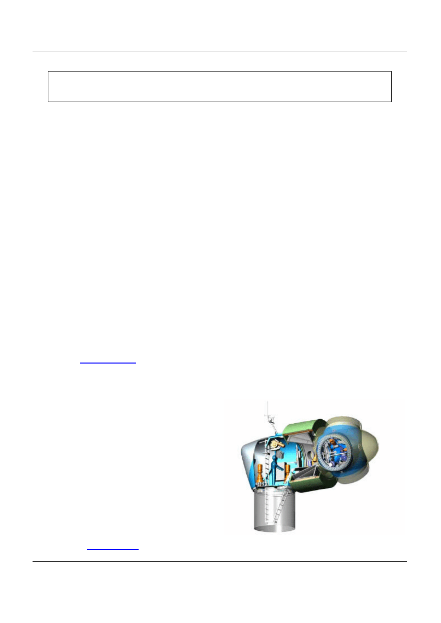
Figure 1: The Z72 wind turbine
Design of the Zephyros Z72 wind turbine with emphasis on
the direct drive PM generator.
Author: C
. J. A. Versteegh, GarradHassan & Partners NL, Sterrelaan 7, 1217 PP, Hilversum NL.
NORPIE 2004, NTNU Trondheim Norway 14 – 16 June, 2004
Z72 Direct drive PMSG
page 2 of 7
CJAV
2
IV. T
HE TURBINE DESIGN
The Z72/2000 (figure 1) is a wind turbine with three GFRP
blades and a steel tubular tower. It has a direct driven multi-
pole synchronous PM generator which is fully integrated in
the stru ctural design. Use is made of a single multiple row roller
bearing on which the hub is mounted on one side and
generator carrier and –rotor on the other side. The stator is
mounted on the opposite side of the carrier which on its turn is
mounted on a compa ct casted nacelle frame. The advantage of
this design is the relative big diameter the load path follows
contrary to the traditional designs with a mainshaft hence
reduces weight .
The turbine is designed according to IEC61400 wind class IB
with exception of the tower (presently only class IIB), defined
by an annual average wind speed at hub height between 7.5
and 8.5 m/s and a maximum turbulence intensity of 16% at 15
m/s wind speed. The rotor speed during power production is
variable. The matching between the available aerodynamic
torque and the produced electromechanical torque of the
generator is determining the rotor speed. The torque-speed
curve is programmed in the frequency converter controller and
the inverter is adapting the generator stator current in
response to the measured generator power frequency. The time
constant of this process is in the order of a few milliseconds.
The control of the generator torque keeps the rotor running at
optimum tip speed ratio for a part of the working range. The
power demand is therefore set proportional to the cube of the
generator speed.
To make the design more attractive for offshore applications an
increase of rotational speed has been proposed in order to
obtain an installed power of 2 MW without any changing.
Offshore the turbine noise (dominated by the rotor and
increasing square with the rotor speed) is not a design driver
and only the voltage level will raise hence with a high enough
insulation value the drive train suits both a 1.5 and a 2 MW
design.
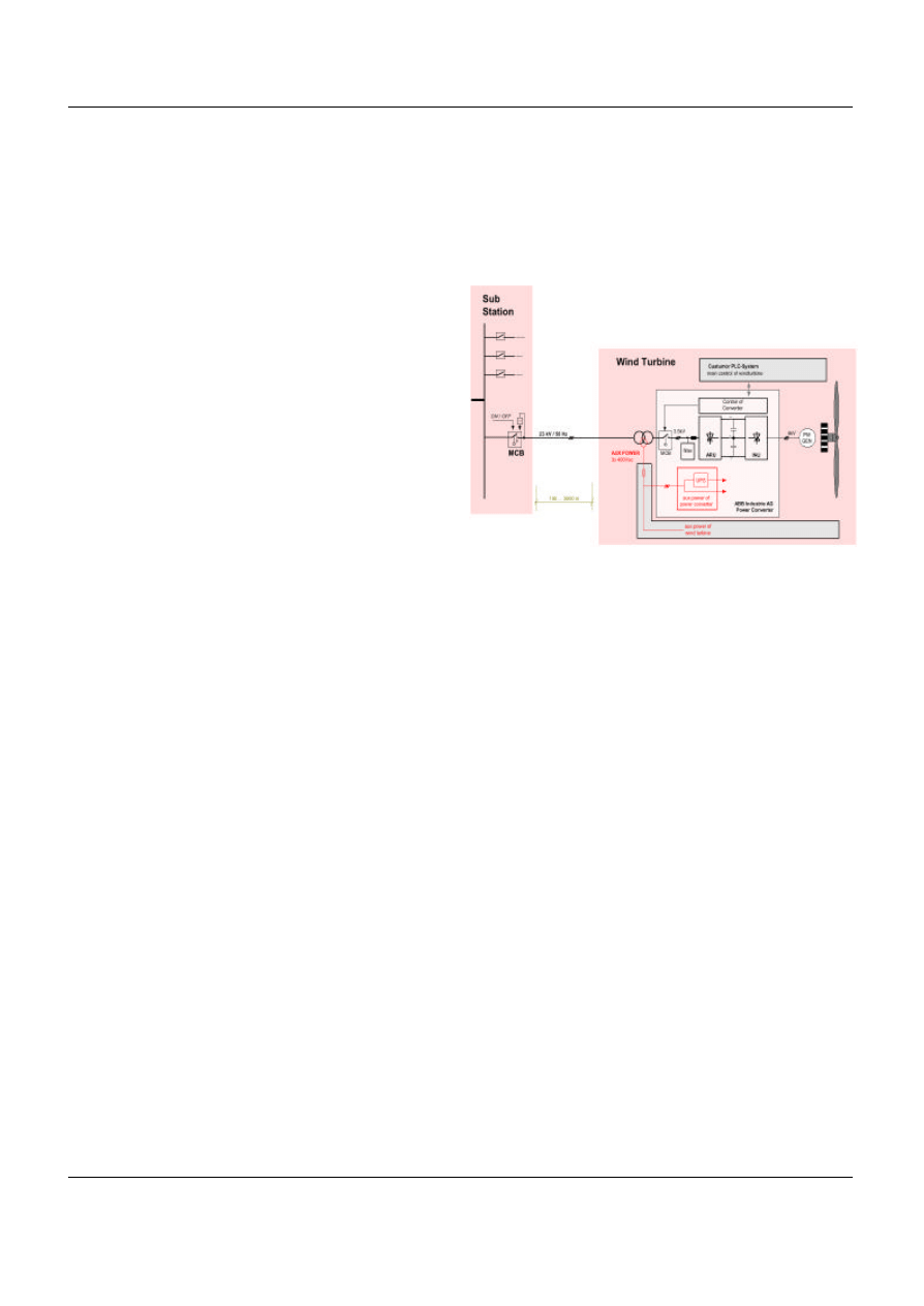
The AC-DC-AC converter in the tower base allows the
generator to operate with a variable speed while the power is
fed into the grid with a constant frequency of 50 Hz (or 60 Hz
for the countries where this applies). It furthermore assures an
average constant power output for wind speeds above rated.
The power factor at the grid side is controllable at standstill as
well as operating. Above rated wind speed, the blade pitch
control maintains a more or less constant rotor speed between
admitted boundaries.
For blade pitching each blade has its own individual pitch
actuator with accompanying pitch angle sensor and a
collective control loop maintains equal blade pitch angles at
the three blades. When the electric power reaches the nominal
value (1.5 or 2 MW), further increase in electric power is
avoided by means of a change in the Q-N curve. As a result of
this the rotor speed increases due to excess aerodynamic
power.
Figure 2: Single line diagram
This in turn is noticed by the rotor speed controller, which
pitches the blades to a larger positive pitch angle (smaller
angle of attack), thereby effectively limiting the rotor speed to
the set value. The rotor speed controller is programmed in the
turbine control system and makes use of advanced routines to
avoid overspeed and tower resonance due to pitch
movements. A wind estimation routine based upon rotor
acceleration monitoring is a further advancement decreasing
overshoot and reducing blade pitch activity.
The hardware of the Z72/2000 control system is built up in a
modular manner. The control and safety functions take place in
the same area or space where the needed measurements and
control or safety actions are performed.
V. T
HE DESIGN PROCESS
The design process has shown a clear design philosophy has
to be adopted what not only is technically driven but also has
to fit on organizational capabilities and possibilities.
Organization structure and available budgets can be a serious
obstacle to success if not properly managed.
The design process is not only characterized by the concept
design, a preliminary design and the detail engineering
resulting in shop drawings, specifications and design reports
but also so-called RAM
(Reliability, Availability,
Maintainability) targ ets have been specified what should in
principle lead to predictable failure rates per main component
or sub-system.
NORPIE 2004, NTNU Trondheim Norway 14 – 16 June, 2004
Z72 Direct drive PMSG
page 3 of 7
CJAV
3
In the early concept and design stages of a technical system it
can be determined that the system will really achieve the
ultimate required availability goal sometime at the end of its
specified lifetime. Studies have shown that after the design
stage is finished (and just before the manufacturing starts)
usually 10% to 20% of the total lifetime expenditures have
already been spent. At the same time about 80% of all lifetime
costs have been locked-in at that moment as well. It is very
clear that the availability
can
be
improved
best
for
the lowest
price and with higher returns before the design process is
closed. This is also known as a ‘reliability data sources
management problem’, that in the practice of wind turbine
design is hard to solve and also require extensive feed -back
from the organization specially the service department. To
build up statistics a track record of a significant number of
turbines is required. Due to this RAM targets are specified
upfront based on actual knowledge and experience but will
have to be verified and adapted when statistic data is available.
Before ABB participated two designs of a DCSG have been
made; water cooled outer rotor type and an air to air cooled
inner rotor type. Cooling of the rotor losses of ca 30 kW or
stator losses of ca 90 kW adds considerable complexity in case
of a fully enclosed design.
Both designs are technically feasible but it became clear the
use of PM could simplify the design considerably. In case of a
PMSG the choice for an inner rotor type without rotor losses
and an outer air cooled stator is obvious.
An advantage also is no rotor excitation current has to be
supplied through a slip ring set but a disadvantage however is
it cannot be disconnected either. This means with increase of
the rotor speed the voltage increases as well. A contactor has
to be used between generator and converter or the insulation
level has to be chosen such that over speed situations never
lead to over voltage on the system. The choice has been made
for the latter because of simplicity and cost.
For enclosure a labyrinth with dust seal has been des igned. A
ventilator is used to pressurize the generator internals. This
system has been patented (publication number WO 01/21956)
Further design criteria for the PMSG have been:
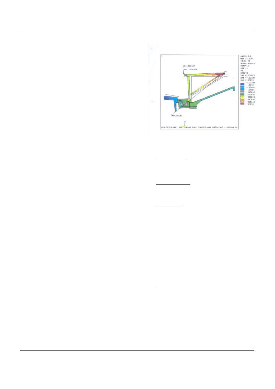
1. Structural design. As the generator structure is part of
the turbine load carrying parts in combination with
the single bearing construction, FEM calculations
have been made by Zephyros (figure 3) to determine
strength and stiffness of structure and bolted
connections. With a nominal airgap of 3 mm and an
active material length of 1200 mm requirements
regarding deformation due to external wind and mass
loads and magnetic loads are strict. A maximum
deflection of ca 2 mm has been calculated under
extreme loads.
The stator and rotor dimensions are more determined
by the required stiffness to minimize deflection
caused by the magnetic pulling forces rather than
material stresses. These calculations have been made
by the ABB research centre in Mannheim Germany.
Figure 3: FEM analyses of the generator structure .
2. Generator mass. The generator mass is important as it
has an impact on the turbine installation. The chosen
concept, rotor speed and airgap diameter determine
the mass.
3. Number of phases . The number of phases is 3 being a
common phase number and simplifies the converter
design.
4. Generator use. The generator has been optimized for
use with a voltage source converter. A back-to-back
converter is used providing maximum control. The
generator is operated at cos f = 1 hence current is
kept in phase with the voltage induced by the airgap
field so the torque produced with the combination of
stator current and airgap field is maximum. Another
advantage of this converter type is the better fault
performance at turbine overspeed (voltage control by
field weakening through reactive current supply) and
loss of electrical load (rated internal e.m.f. in the
concept is 10 – 15% higher than the stator voltage
hence DC link voltage would not exceed the rated
value).
5. Voltage level. A 7.5 kV insulation level has been
chosen. It is believed with the increase of nominal
power the voltage should increase and not the
current. The choice is made for a medium voltage
converter with fewer components than a low voltage
converter and a better efficiency. Past years however
LV converter have strongly developed and up to 2
MW are still cheaper. Nevertheless overall cost
assessment show the MV solution can compete but
the converter lacks the cost reduction due to limited
production number of MV semi-conductors.
NORPIE 2004, NTNU Trondheim Norway 14 – 16 June, 2004
Z72 Direct drive PMSG
page 4 of 7
CJAV
4
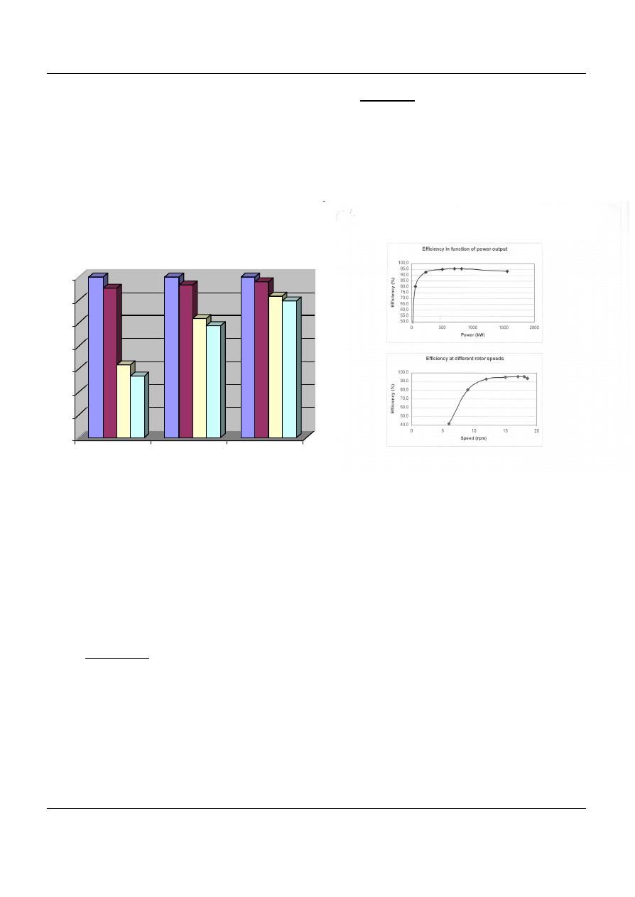
In figure 4 for three wind climates with a yearly
average of 5, 7 and 10 m/s the relative energy output
has been calculated for 4 wind turbine types with the
only difference: the conversion system. PMHV is de
Zephyros turbine; WRLV (wound rotor low voltage)
is a design like the Lagerwey and Enercon designs
PMLV is used by the manufacturers WinWind,
Vensys, Leitner and MTorres. WRHV is added for
comparison but is a non existing design. In an average
wind climate (7 m/s) PMHV produces 2% more than
WRLV due to avoiding rotor losses and a higher
converter efficiency.
Figure 4: Influence of generator type and voltage level
on performance.
At low wind sites with more partial load hours the
advantage is more obvious than at high wind sites
with a higher capacity factor.
For locations where a higher noise level can be
accepted (off shore) the generator is upgraded to 2
MW by increasing the rotational speed of the turbin e.
With an equal airgap torque and an increased voltage
to 4000 V the nominal power is increased at minor
extra cost due to the chosen voltage insulation level
in both generator and converter.
6. Stator winding. Pre-formed or flat wire has been used
what is inherent to the chosen insulation level. No
mass produced round wire can be used what on its
self is cheaper but the insulation quality is less. The
slot fill factor of 0.7 is better than 0.45 for round wire
what saves weight on active material. The
disadvantage of flat wire is the bigger number of
connections and the necessity to use magnetic slot
wedges. The stator is vacuum impregnated.
7. PM material. For the magnet material Neodymium-
Iron-Boron (NdFeB) is used. The cost of high energy
product (BH product) magnets has reduced in price
with a factor 5 in 10 years time and now cost less than
50 €/kg.
The magnets are glued on steel modules and then
magnetized. These modules are bolted on the rotor
and a GRP bandage is wrapped around the rotor
before coating.
Figure 5: Generator efficiency as a function of power
and rotational speed.
The blades are commercially available but had had to be
verified for the Z72 load spectrum. The loads are calculated
with a computer code with following input:
1. Model of the wind spectrum
2. Model of the pitch and generator control
3. Aerodynamic model of the blades
4. Dimensions and mass and stiffness distribution.
The loads are calculated in the time domain and are rain flowed
and presented in Markov matrices containing mean values,
amplitudes and number of cycles for different
locations of the turbine in three directions and/or resulting
loads).
Critical bolt connections of blade-bearing-hub and hub-
bearing-generator/nacelle as well as the hub, generator and
nacelle structures are designed with use of FEM calculations.
86
88
90
92
94
96
98
100
[%]
5
7
10
Windspeed
Influence of generator type and voltage level on performance
PMHV
PMLV
WRHV
WRLV
NORPIE 2004, NTNU Trondheim Norway 14 – 16 June, 2004
Z72 Direct drive PMSG
page 5 of 7
CJAV
5
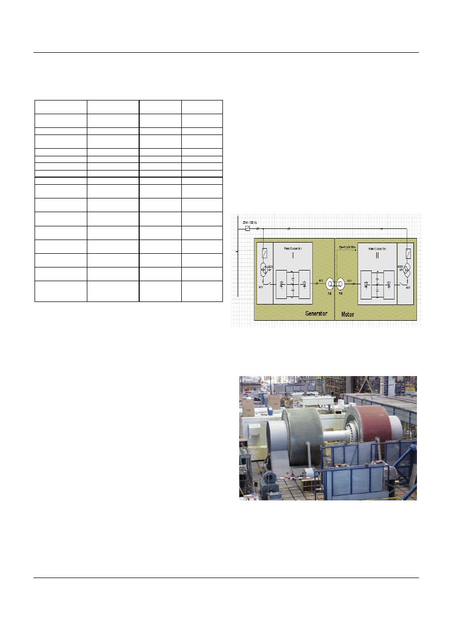
Table 1: Generator specifications.
Rated shaft power
1670 kW
Temperature
rise class
F
Rated electrical
power
1562 kW
Insulation class
F (H)
Rated air gap torque
862 kNm
Standards
IEC34
Rated voltage
3000 V
Protection by
enclosure
IP54
Rated current
327 A
Cooling type
IC40
Power factor
0.92
Rotor inertia
35000 kgm
2
Frequency
3 - 9.25 Hz (rated)
Total weight
47200 kg
Rotational speed
9 - 18.5 rpm (rated)
Stator weight
25000 kg
Pole number
60
Rotor weight
12500 kg
Pole angle
33.5 deg.
Bearing
support cone
5000 kg
Torque harmonics
100% fundamen tal
(862 kNm)
Bearing weight
4000 kg
< 1% 6
th
harmonic
(55.5 Hz)
PT 100 stator
6
< 1% 12
th
harmonic
(111 Hz)
PT 100
generator air
2
< 1% 24
th
harmonic
(222 Hz)
PT 100 bearing
2
Short circuit current
569 A (sustained)
Airgap distance
sensors
4
Ambient temperature
40 °C
Bearing
greasing unit
1
Radial pull
98 kN/mm between
stator and rotor due
to excentricity
Maximum
magnetic force
45 kN magnetic
pulling force of
one pole.
VI. T
ESTING
The generator has been manufactured and tested in the ABB
factory in Helsinki. In the factory 2 systems are mounted back
to back as drive equipment with low rpm and such high torque
are not available. Two synchronous generators are
mechanically coupled. The two generators have been cooled
with external fans and a speed and a position signal of the
motor generator shaft had to be provided for overspeed tests .
The power converter Nr 1 on the left side of figure 6 is the
device under test, the other one gives the load for the
generator. Due to the losses in the converters, motor and
generator, the output power of the converter on the generator
side is reduced by ca. 15 %. This resulted in a power of ca. 1.5
MW of the converter of the generator side hence test at
maximum current could be executed.
Following tests have been exe cuted (in this overview limited to
the generator):
1. Light load test. Each drive train is tested on its own
with no load. This is to check the normal function.
Protection. Protecting levels and functions are
checked by forcing different faults to the converters.
2. Overspeed. This test is to check the external
overspeed protection.
3. Force generator short circuit. This test is to determine
the short circuit current and peak value of the torque.
4. Firing through. This test is to check the mechanical
strength of the DC link and the braking capacity of
the main circuit braker.
5. Continuous load test. This test is to proof if the drive
train meets the specifications in steady state
conditions. The power will be ramped up to the
maximum. Following parameters have been mo nitored:
temperatures of generator, converter and main
transformer, speed, load angle, frequency of the
generator, generator power, power of auxiliaries , grid
power output, total losses of test bench and
interactions generator – converter.
6. Optimization of the grounding concept and the flange
filter to minimize the influence (dv/dt, common mode
and differential mode voltage) to the generator.
7. Fast variation of torque to optimize the closed loop
control.
Figure 6: Generator test bench schematics.
Figure 7: The tes t bench.
NORPIE 2004, NTNU Trondheim Norway 14 – 16 June, 2004
Z72 Direct drive PMSG
page 6 of 7
CJAV
6
The converter system and generator have fulfilled its
requirements in normal and extraordinary conditions. The
measured values of the drive train lie within its limits. The
system has proven for a given active power reference the
generator is able to track it very closely with fast dynamic
response.
The reactive power to the generator is controllable in such a
manner that the terminal voltage has not exceeded the rated
value.
The test had some limitations:
1. The dynamic tests could not be carried out with
nominal load. The reason for this is the very low
inertia which is ca 40 times smaller than with the
turbine rotor mounted.
2. The cooling is not according real circumstances as no
wind is present. The influence of switching on some
external cooling fans could clearly be measured and
gave comfort. Cooling in practice only can be tested
on site .
Other tested components have been:
1. Blade. The behavior under the fatigue and extreme
loads.
2. Pitch drive. The durability on endurance loads and
thermal behavior due to extreme loads.
3. Control cubicle. Vibration test, salt spray test and
thermal test to meet specifications regarding
corrosion, vibration and temperature range.
4. Control software. System and response test in the
workshop to compare with the response of the
computer model.
VII. O
PERATIONAL EXPERIENCE
The turbine has been installed in April 2002 and became fully
operational in November 2003. The first year of operation the
overall availability has been 84% and to date 4700 MWh have
been produced. For the site (Maasvlakte near Rotterdam, The
Netherlands) this means a capacity factor of 27%. If this is
corrected for an expected availability of 97% it would lead to
31% what is excellent for a site with an average wind speed at
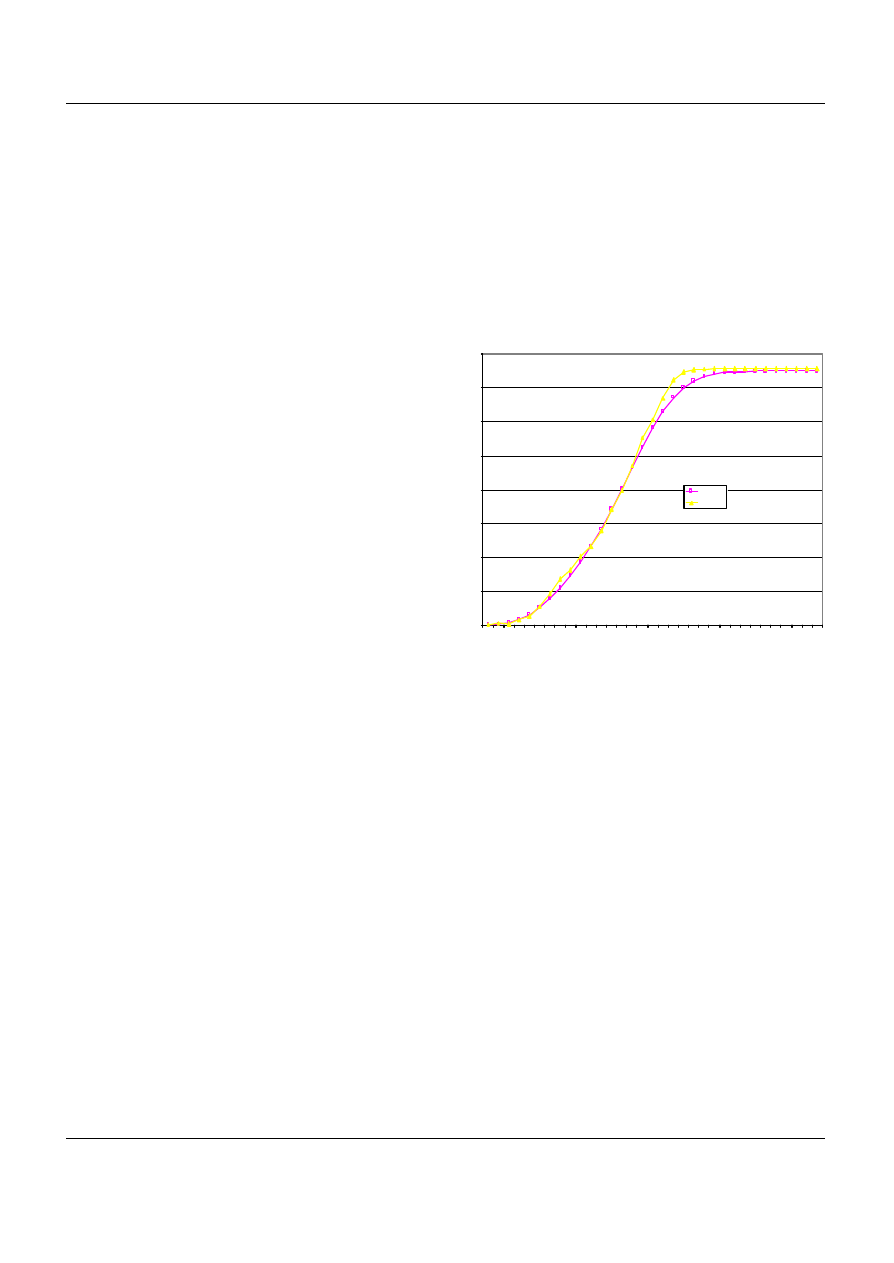
hub height of 7.5 m/s. The measured power curve (as a
function of the wind speed and measured acc to IEC61400-12)
given in fig. 8 shows good comparison with the calculated
curve and supports the excellent performance of the high
voltage generator-converter system.
An initial problem has been the noise generated by resonance
of tower shell sections due the switching frequency (480 Hz) of
the semiconductors. This has been solved by changing the
frequency to 800 Hz.
A heat run has been performed being a period of 24 hours
continuously at full load. At an ambient temperature of 0 °C the
maximum stator temperature does not exceed 75 °C. The
maximum generator temperature measured past summer was 86
°C at an ambient temperature of 17 °C. For cooling ventilation
is applied for bearing and electronics in hub and nacelle.
Most of the operational problems were in the components that
have been adopted from the existing Lagerwey design but
should have been paid more attention in the up scaled design
although also Q A aspects contributed to it. It concerns wear
and malfunctioning of the service brake and a lack of control
on the yaw brake passive torque to avoid overload on the yaw
drives. The design has been adapted on these points.
Figure 8: Measured power curve and calculated power curve
0
200
400
600
800
1000
1200
1400
1600
1 2 3 4 5 6 7 8 9 10 11 12 13 14 15 16 17 18 19 20 21 22 23 24 25 26 27 28 29 30 31 32 33
Wind speed [m/s]
Power [kW]
Calculated
Measured
NORPIE 2004, NTNU Trondheim Norway 14 – 16 June, 2004
Z72 Direct drive PMSG
page 7 of 7
CJAV
7
VIII. B
ENEFITS AND
C
OST
Although the Z72 can compete with turbines in the same
power range, margins still can improve by taking advantage of
series production. Common catalogue prices start at 1500 k€.
The benefits are in the cost of operation:
1. Reduced maintenance cost due to limited number of
components and systems.
2. Higher energy output (2%)
3. Few moving and wearing parts hence eventually
lower insurance cost.
4. Due to the full power 4q converter good grid
connectivity; universal 50 - 60 Hz design, electric
braking and positioning of turbine rotor, and capable
to operate under line dips.
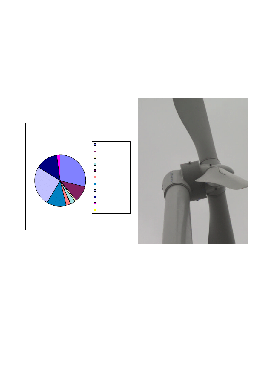
Figure 9: Typical cost distribution of a DD wind turbine.
IX. F
UTURE DEVELOPMENT
The short term development is an upscale of the turbine rotor
in order with the same rated power and generator design to
increase the energy capture thus improving the price
performance ratio of at least 10%.
The long term development is a recent started government
supported concept study to develop a 4 – 5 MW turbine with
similar concept. The first phase has to result in a bid book and
a preliminary design before the end of 2004.
X. C
ONCLUSION
The design has proven to work and the decision to do a full
scale conversion system test has considerably shortened the
prototyping. The integration of the generator in the structural
design leads to a very compact design and saves weight.
Although first sales are realized (30 pcs), even for this number
of turbines a price reduction already is realized. The volume
however should increase to improve the margins.
Figure 10: The Z72
distribution of costing
29%
10%
1%
3%
0%
3%
12%
25%
15%
2%
0%
rotor :
drivetrain:
hydraulic:
nacelle:
cover :
yaw mechanism:
tower:
generator:
E-system/converter:
transformer :
auxiliary equipment:
Wyszukiwarka
Podobne podstrony:
Modeling Of The Wind Turbine With A Doubly Fed Induction Generator For Grid Integration Studies
MEPC 154(55) Designation of the Southern South African waters as a Special Area
Design of the packaging
06 Wind Turbine With Asynchronous
Design Requirements For Medium Sized Wind Turbines For Remote And Hybrid Power Systems
(Wind) A Low Speed, High Torque, Direct Drive Permanent Magnet Generator For Wind Turbines
Wind Turbine Design Codes A Preliminary Comparison of the Aerodynamics
[2001] State of the Art of Variable Speed Wind turbines
1801 Design Analysis of Fixed Pitch Straight Bladed Vertical Axis Wind Turbines
Advanced Methods for Development of Wind turbine models for control designe
[2001] State of the Art of Variable Speed Wind turbines
[2001] State of the Art of Variable Speed Wind turbines
Design Of Direct Driven Permanent Magnet Generators For Wind Turbines
Design Fatigue Test and NDE of a Sectional Wind Turbine Rotor Blade
CEI 61400 22 Wind turbine generator systems Required Design Documentation
więcej podobnych podstron