
* Corresponding author.
E-mail address: songyd@ncat.edu (Y.D. Song)
Journal of Wind Engineering
and Industrial Aerodynamics 85 (2000) 293}308
Variable speed control of wind turbines using
nonlinear and adaptive algorithms
Y.D. Song
*, B. Dhinakaran , X.Y. Bao
Department of Electrical Engineering, North Carolina A&T State University, Greensboro, NC7411, USA
Department of Electrical Engineering, University of Virginia, Charlottesville, VA 22903, USA
Abstract
Automatic control represents one of the most important factors responsible for the e$ciency
and reliability of wind power conversion systems. Thus far, only a few isolated applications of
conventional control to wind power systems have appeared in the literature. To make wind
power generation truly cost-e!ective and reliable, advanced control techniques are imperative.
In this paper we develop a control scheme for wind turbine using nonlinear and adaptive
control theory. Based on both mechanical and electrical dynamics, nonlinear and adaptive
control algorithms are derived to on-line adjust the excitation winding voltage of the generator.
This method is shown to be able to achieve smooth and asymptotic rotor speed tracking, as
justi"ed by both analysis and computer simulation.
2000 Elsevier Science Ltd. All rights
reserved.
Keywords: Wind turbine; Variable speed control; Adaptive control; Nonlinear control; Stability
1. Introduction
Several key areas of research in control of wind turbines have been identi"ed during
the recent workshop held at Santa Clara University [1]. Of particular interest to wind
power industry is the development of innovative control algorithms for smoother and
more ezcient operation of wind power generation systems. Traditionally, most wind
turbines operate at "xed speeds except when starting and stopping [2]. Fixed-speed
operation means that the maximum coe$cient of performance is available only at
a particular wind speed. A low coe$cient of performance is observed for all other
0167-6105/00/$ - see front matter
2000 Elsevier Science Ltd. All rights reserved.
PII: S 0 1 6 7 - 6 1 0 5 ( 9 9 ) 0 0 1 3 1 - 2
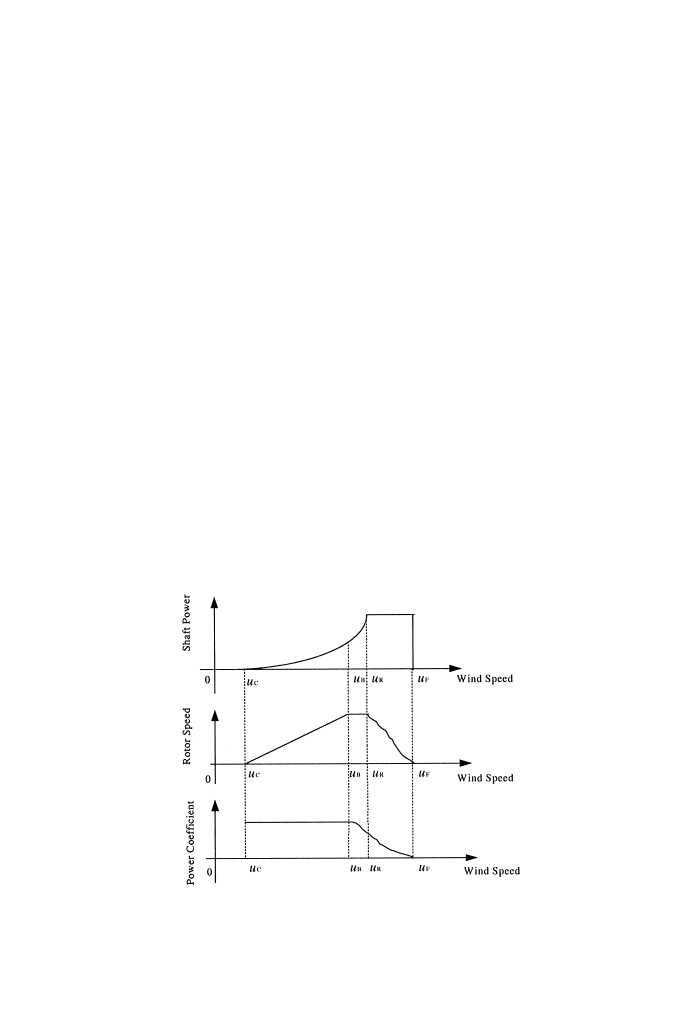
Fig. 1. The operation modes of turbine speed.
wind speeds, which reduces the energy output below that which might be expected
from variable speed operation [3}13].
As noted by several researchers (e.g. Refs. [3,10,11]), to e!ectively extract wind
power while at the same time maintaining safe operation, the wind turbine should be
driven according to the following three fundamental modes associated with wind
speed, maximum allowable rotor speed and rated power, i.e.,
Mode 1 * operating at variable speed/optimum tip-speed ratio:
u)u)u ,
Mode 2 * operating at constant speed/variable tip-speed ratio:
u )u)u0,
Mode 3 * operating at variable speed/constant power:
u0)u)u$,
which are illustrated in Fig. 1, where u! is the cut-in wind speed, u denotes the wind
speed at which the maximum allowable rotor speed is reached, u0 is the rated wind
speed and u$ is the furling wind speed at which the turbine needs to be shut down for
protection.
It is seen that if high-power e$ciency is to be achieved at lower wind speeds, the
rotor speed of the wind turbine must be adjusted continuously against wind speed.
A common practice in addressing the control problem of wind turbines is to use
linearization approach. This method allows the linear system theory to be applied in
control design and analysis. However, due to the stochastic operating conditions and
294
Y.D. Song et al. / J. Wind Eng. Ind. Aerodyn. 85 (2000) 293}308

the inevitable uncertainties inherent in the system, such a control method comes at the
price of poor system performance and low reliability [11}13].
In this work we present a method for variable speed control of wind turbines. The
objective is to make the rotor speed track the desired speed that is speci"ed according
to the three fundamental operating modes as described earlier. This is achieved by
auto-adjusting the excitation winding voltage of the generator through the developed
nonlinear and adaptive control algorithms. Such a control scheme leads to more
energy output without involving additional mechanical complexity to the system. Test
of the proposed method based on a two-bladed horizontal axis wind turbine similar to
DOE MOD-0 is conducted. Several operating conditions are simulated and satisfac-
tory results are obtained.
2. System modeling
The power extraction of wind turbine is a function of three main factors: the wind
power available, the power curve of the machine and the ability of the machine to
respond to wind #uctuation. The expression for power produced by the wind is given
by [1}3]
P(u)" C(j, b)opRu,
(1)
where
o is air density, R is radius of rotor, u is wind speed, C denotes power
coe$cient of wind turbine,
j is the tip-speed ratio and b represents pitch angle. Note
that the tip}speed ratio is de"ned as
j"
R
u
u
,
(2)
where
u is the rotor speed. It is seen that if the rotor speed is kept constant, then any
change in the wind speed will change the tip-speed ratio, leading to the change of
power coe$cient C as well as the generated power out of the wind turbine. If,
however, the rotor speed is adjusted according to the wind speed variation, then the
tip-speed ratio can be maintained at an optimal point, which could yield maximum
power output from the system.
From Eqs. (1) and (2) we can see that
P(u)"ku,
(3)
where
k"
1
2
Cop
R
j
.
For a typical wind power generation system, the following simpli"ed block diagram
(Fig. 2) is used to illustrate the fundamental work principle. We see that such a system
primarily consists of an aeroturbine, which converts wind energy into mechanical
energy, a gearbox, which serves to increase the speed and decrease the torque and
Y.D. Song et al. / J. Wind Eng. Ind. Aerodyn. 85 (2000) 293}308
295
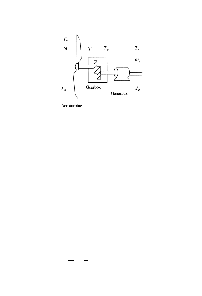
Fig. 2. Schematic diagram of wind power system.
a generator to convert mechanical energy into electrical energy. Driving by the input
wind torque ¹, the rotor of the wind turbine runs at the speed u. The transmission
output torque ¹ is then fed to the generator, which produces a shaft torque of ¹ at
generator angular velocity of
u. Note that the rotor speed and generator speed are
not the same in general, due to the use of the gearbox.
The dynamics of the system can be characterized by the following equations:
¹!¹"
Ju#Bu#Kh,
(4)
¹!¹"
JuBu#Kh,
(5)
¹u"¹u
,
(6)
where B, K, B, K are the friction- and torsion-related constants, ¹, ¹, ¹,
¹
the shaft torque seen at turbine end, generator end, before and after gear box, J,
J the moment of inertia of the turbine and the generator, and u,˜u the angular
velocity of the shaft at turbine end and generator end.
c the gear ratio is de
"ned as
c"
u
u
.
(7)
Upon using Eqs. (6) and (7), we can combine Eqs. (4) and (5) to get
J
u#Bu#Kh"¹!c¹
or equivalently
J
u#Bu#Kh"
P
u
!
c
P
u
(8)
296
Y.D. Song et al. / J. Wind Eng. Ind. Aerodyn. 85 (2000) 293}308

with
J"J#cJ,
B"B#cB,
K"K#cK,
where P denotes the wind power given by Eq. (3) and P represents the electric
power generated by the system. It is well known that P is related to the excitation
current of the generator via [5]
P"K
(
uc(I).
(9)
where K
(
is a machine-related constant, c(.) is the #ux in the generating system, and
I is the "eld current. In this work we consider the case that the system is operating
over the nonlinear but nonsaturation magnetic range. This can be ensured by suitable
pre-compensation. The exciter dynamics of the system is governed by
¸
I
Q #IR"u,
(10)
where ¸ is the inductance of the circuit, I the "eld current, R the resistance of the
rotor "eld, and u the "eld voltage.
In designing the control scheme for the system, both the rotor dynamics (8) and the
exciter dynamics (10) must be considered in order to achieve good control perfor-
mance. We shall address this issue in detail in next section.
3. Control design
The rotor speed of the wind turbine is controlled through the adjustment of
excitation winding voltage, as shown in Fig. 3. The main idea behind this method is to
control the reaction torque (power) of the generator via changing the winding voltage,
so that the rotor speed is correspondingly adjusted. As such, the control problem can
be stated as follows: Design a control voltage (< ) such that the rotor speed (u) of the
wind turbine closely tracks the desired speed (
uH) given according to the three operational
modes. It is assumed that
uH, uH, u
K H are bounded.
3.1. Nonlinear Variable Speed Control
For later development, we rewrite Eqs. (8) and (10) as
u"
G
aGG!Ac(I)
(11a)
and
I
Q "bu!aI,
(11b)
Y.D. Song et al. / J. Wind Eng. Ind. Aerodyn. 85 (2000) 293}308
297
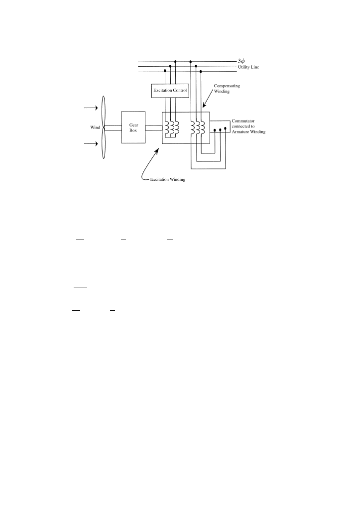
Fig. 3. Wind power system with "eld excitation.
where
a"
k
J
,
a"!
B
J
,
a " !
K
J
,
"u, "u, "
R
u dq,
A"
cK
(
J
,
a"
R
¸
and b"
1
¸
.
To design the tracking controller, let us de"ne the rotor tracking error as
e"
u!uH.
(12)
It then follows that
e
"
G
aGG!Ac(I)!u
H.
(13)
Now, we need to design a control scheme such that the tracking error e converges to
zero. To this end, we express Eq. (13) as
e
"!ke#z,
(14)
where
z"
G
aGG#ke!Ac(I)!u
H
(15)
298
Y.D. Song et al. / J. Wind Eng. Ind. Aerodyn. 85 (2000) 293}308

and k'0 is a design constant. It is interesting to note that if z as de"ned in Eq. (15)
is made to approach zero as tPR, then eP0 as tPR. Thus our attention now is
focused on making zP0. First we take derivative of Eq. (15) w.r.t. time to get
z
"
G
aG
*G
*u
u!A
*c
*I
I
Q #ke!uKH
(16)
Substituting for
u, e and IQ in the above equation gives
z
"F!bu,
(17)
where
F"
G
aG
*G
*u
#
k
G
aGG!Ac(I)
#
Aa
*c
*I
I!ku
H!
u
K H,
b"Ab
*c
*I
.
(18)
If we design the control voltage u so that
u"
1
b
(F#kz),
(19)
where k'0 is a design constant, we obtain
z
"!kz
(20)
from which we readily have that ztends to zero as time increases. To summarize, we
have the following result.
Theorem 1. Consider the wind power generation system given by Eq. (8) with the xeld
exciter as shown in Eq. (10). If the xeld voltage is adjusted according to Eq. (19), in which
z is calculated by Eq. (15) and F is generated by Eq. (18), then the rotor speed is
ensured to track the desired speed asymptotically.
Proof. The result can be justi"ed by considering the Lyapunov function candidate
<"
0.5e
#0.5z,
which leads to
<
Q "!
e
z
2
k !1
0
k
e
z
)!
min(k, k)
e
z
.
Regarding the control scheme, the following convergence result can be established.
Theorem 2. The convergent rate of the tracking error with the proposed control can be
found as e
\JR, where l"min(k, k).
Y.D. Song et al. / J. Wind Eng. Ind. Aerodyn. 85 (2000) 293}308
299

Proof. In fact, from Eqs. (14) and (20), we have
e(t)"e(0)exp
\I
R#exp\I
R
R
exp
I
Rz(q) dq
and
z(t) " z(0)e\I
R.
Therefore, it can be veri"ed that
e(t)"
e(0) exp
\I
R#<(0)t exp\I
R
if k"k,
e(0) exp
\I
R#
z(0)
k!k
(exp
\I
R!exp\I
R) otherwise,
implying the convergent rate of the tracking error is at least
l"min(k, k).
Remark. The proposed control scheme can be realized by simply specifying the
design parameters k'0 and k'0. There is no ad hoc or trial and error process
involved.
It should be mentioned that the control scheme is based on the assumption that
all the system parameters are available during system operation. New control
algorithms are needed if unknown parameters are involved. We address this issue in
next section.
3.2. Adaptive Variable Speed Control
In practice, those parameters such as k, B and K may not known precisely. For
this reason, we now consider the control problem in which the parameters aG are
unknown. Let a(G be the estimate of aG and aG be the estimate error de"ned by
a
G"aG!a(G. Motivated by the backstepping method [6], we rewrite the error dy-
namic equation as
e
"!ke#z?#
G
a
GG,
(21)
where
z
?"
G
a(GG!Ac(I)!u
H#ke.
(22)
To derive the control scheme, we take derivative of the above equation and substitu-
ting for
u, e and IQ to get
z
?"a(G#
a
(
G
*G
*u
#
k
(!ke#aGG#z?)
!
A
*c
*I
bu#Aa
*c
*I
I#a(G
*G
*u
uH!u
K H
"
F?!b?u#
a
(
G
*G
*u
#
k
(
aGG),
(23)
300
Y.D. Song et al. / J. Wind Eng. Ind. Aerodyn. 85 (2000) 293}308

where
F?"a(GG#
a
(
G
*G
*u
#
k
(!ke#z?)
#
Aa
*c
*I
I!a(G
*G
*u
uH!u
K H,
(24)
b?"Ab
*c
*I
.
(25)
Now if the control voltage is adjusted by
u"
1
b?
(k?z?#F?),
(26)
the error dynamics become
z
?"!k?z?#
a
(
G
*G
*u
#
k
(
aGG).
(27)
Consider the Lyapunov function candidate
<"
1
2
e
#
1
2
z
?#
1
2
aG.
(28)
Di!erentiating V along trajectory (27) leads to
<
Q "ee#z?z?!aGa(G"e(!ke#z?#aGG)
#
z?
!
k?z?#
a
(
G
*G
M
u
#
k
(
aGG)
!
aGa(G
(29)
"!
ke!k?z?#ez?#aG
e
G#z?
a
(
G
*G
*u
#
k
G!a(G
.
(30)
If the estimate parameters a(G are updated via
a(
G
"
e
G#
a
(
G
*G
*u
#
k
Gz?,
(31)
then
<
Q "!ke!k?z?#ez?
(32)
"
(ez?)
!
k 1
0
!
k?
e
z?
4!
j(k, k?)(e#z?)40.
(33)
Therefore, we have
e3¸5¸, z?3¸5¸ and aG(i.e., a(G) 3 ¸.
Y.D. Song et al. / J. Wind Eng. Ind. Aerodyn. 85 (2000) 293}308
301

From (22) we see that the boundedness of z?, e and a(G ensures that Ga(GG is
bounded. Thus
G 3 ¸. Therefore GaGG 3 ¸, which, in view of Eq. (22), leads
to e
3 ¸. By Barbalat Lemma [6], we can conclude that both e and z? converge to
zero asymptotically and a(G remain bounded. Thus the following result is established.
Theorem 3. Consider the wind power generation system given by Eq. (8) with the xeld
exciter as shown in Eq. (10). If the xeld voltage is adjusted according to Eq. (26), where
z? is generated by Eq. (22) and a(G are updated by Eq. (31), then the rotor speed tracks the
desired speed asymptotically.
Remark. The power coe$cient k represents one of the most di$cult parameters to
be obtained because of its dependence on operating-point. The control scheme
developed here does not rely on the precise value of k, which could prove useful in
practice.
4. Simulation study
The simulation study was performed to verify the e!ectiveness of the proposed
control algorithms. The following system parameters are considered.
R"0.02X, ¸"0.001H,
<J"480 <, J"16Kg!m, P"8, c"37.5,
f"60Hz,
k"3, B"52, K"52, k
(
"
1.7.
The control parameters are chosen as
k"2, k"54, k?"54.
The "rst simulation conducted was the tracking of the following desired trajectory
uH"2#sin(t) (rad/s).
The tracking pro"le is shown in Fig. 4. The tracking error and the control voltage
are depicted in Figs. 5 and 6, respectively. Fig. 7 shows the estimate parameters. It is
seen that both nonlinear and adaptive control schemes lead to good tracking
performance.
The second simulation is based on a more practical situation. Namely we consider
a two-bladed horizontal-axis wind turbine similar to DOE MOD-0 [4] as shown in
Fig. 8. The speci"cation of the wind turbine is given in Table 1.
The rotor speed (
u) is to be adjusted to follow the following desired trajectory:
uH"
0,
u(k)(u,
X(1#sin
p
2
(u(k)!s)
d
,
u(k)(u,
X,
u(k)(u,
X(1!sin
p
2
(u(k)!s)
d
,
u(k)(u,
0,
u(k)'u,
302
Y.D. Song et al. / J. Wind Eng. Ind. Aerodyn. 85 (2000) 293}308
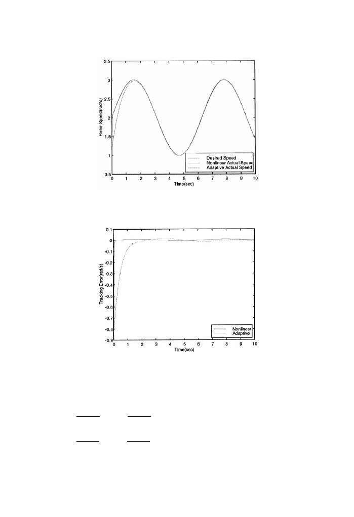
Fig. 4. Tracking process with nonlinear and adaptive control.
Fig. 5. Tracking error.
where
s"
u#u
2
,
d"
u!u
2
,
s"
u#u
2
,
d"
u!u
2
,
u"21.3 m/s, X"4.1 rad/s.
Y.D. Song et al. / J. Wind Eng. Ind. Aerodyn. 85 (2000) 293}308
303
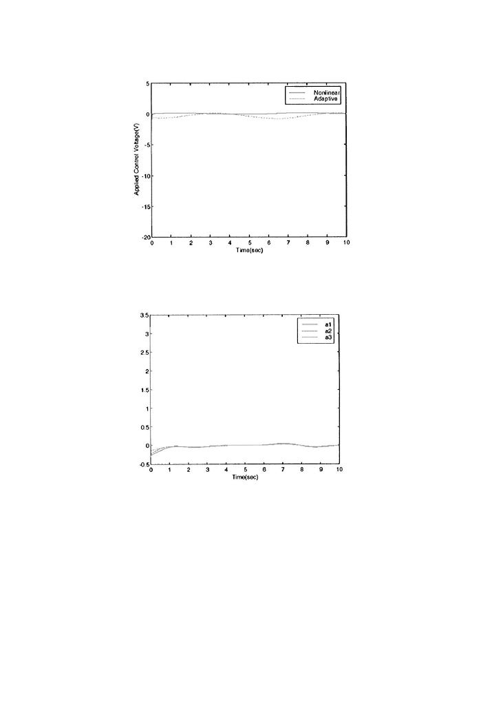
Fig. 6. Control voltage.
Fig. 7. Estimate parameters.
Note that X(rad/s) is speci"ed according to the allowable rotor speed (r/m of the
wind turbine (Figs. 9 and 10). The values for u, u, u are given in Table 1 and u is so
chosen to give a smooth shutdown pro"le.
It is observed that for both low and high wind speed, the proposed control is able to
achieve smooth and precise asymptotic speed tracking. All the internal signals are
bounded. We have tested a number of operating points and similar results are
obtained (Figs. 11}13).
304
Y.D. Song et al. / J. Wind Eng. Ind. Aerodyn. 85 (2000) 293}308
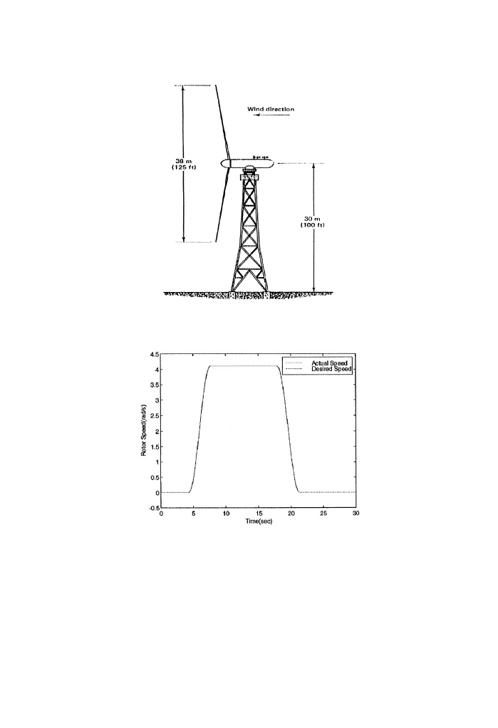
Fig. 8. General view of MOD-0 wind turbine.
Fig. 9. Rotor Speed Tracking with Nonlinear Control.
5. Conclusion
Variable speed operation of wind turbine is necessary to increase power generation
e$ciency. A nonlinear wind turbine control method is explored in this paper. This
method is based on the regulation of excitation winding voltage of the generator.
Y.D. Song et al. / J. Wind Eng. Ind. Aerodyn. 85 (2000) 293}308
305
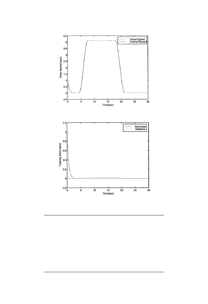
Fig. 10. Rotor Speed Tracking with Adaptive Control.
Fig. 11. Tracking error.
Table 1
Allowable rotor speed
40 r/m
Generator output power
100 kW
Optimal coe$cient of performance C
0.375
Cut-in wind speed u
4.3 m/s
Rated wind speed u
7.7 m/s
Furling wind speed u
17.9 m/s
Rotor diameter
37.5 m
Hub height
30 m
Coning angle
73
E!ective swept area
1072 m
Weight of blades
2090 kg
Generator voltage
480 V
306
Y.D. Song et al. / J. Wind Eng. Ind. Aerodyn. 85 (2000) 293}308
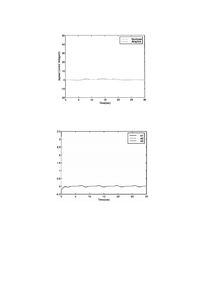
Fig. 12. Control voltage.
Fig. 13. Estimate parameters.
Based on both mechanical and electrical dynamics, nonlinear and adaptive control
algorithms are derived. Analysis and simulation show that the proposed method is
able to achieve smooth and satisfactory rotor speed tracking. In addition, we have
carried out a comparison study between the proposed method and the tradition
constant speed control method. We found that under the same operating conditions
the proposed method is able to gain more power if the wind turbine is operated at
variable speed mode by the proposed scheme.
Y.D. Song et al. / J. Wind Eng. Ind. Aerodyn. 85 (2000) 293}308
307

Acknowledgements
This work was partially supported by the U.S. National Renewable Energy Labor-
atory under subcontract REP No. RCX-7-16469.
References
[1] Mike Robinson, Paul Veers, Wind Turbine Control Workshop, Santa Clara University, Santa Clara,
CA, June, 1997.
[2] S.A. Salle, D. Reardon, W.E. Leithead, M.J. Grimble, Review of wind turbine control, Int. J. Control
52 (6) (1990) 1295}1310.
[3] E. Muljadi, C.P. Butter"eld, P. Migliore, Variable speed operation of generators with rotor-speed
feedback in wind power applications, Fifteenth ASME Wind Energy Symposium, Houston, Texas,
1996.
[4] G.L. Johnson, Wind Power Systems, Prentice-Hall Inc., Englewood Cli!s, NJ, 1985.
[5] A.R. Bergen, Power System Analysis, Prentice-Hall, Englewood Cli!s, NJ, 1996.
[6] I. Kanellakopoulos, P.V. Kokotovic, A.S. Morse, Systematic design of adaptive controllers for
feedback linearizable systems, IEEE Trans. Automat. Control 36 (1991).
[7] T. Thirnger, J. Linders, Control of variable speed of a "xed-pitch wind turbine operating in a wide
speed range, IEEE Trans. Energy Conversion 8 (3) (1993) 520}526.
[8] W.E. Leithead, Dependence of performance of variable speed wind turbine on the turbulence,
dynamics and control, IEE proc. 137 (6) (1990).
[9] M. Steinbuch, O.H. Bosqra, Optimal output feedback of a wind energy conversion system, Power
systems modeling and control applications, in: A.J. Calvaer (Ed.), IFAC Proceeding series, No. 9,
1989.
[10] D.J. Leith, W.E. Leithead, Implementation of wind turbine controllers, Int. J. Control 66 (3) (1997)
349}380.
[11] A. McIver, D.G. Holmes, P. Freere, Optimal control of a variable speed wind turbine under dynamic
wind conditions, IAS'96 Conference Record of the IEEE Industry Applications Conference Thirty-
First IAS Annual Meeting, 1996.
[12] Donald S. Zinger, Eduard Muljadi, Andrew Miller, A simple control scheme for variable speed wind
turbines, IAS'96 Conference Record of the IEEE Industry Applications Conference 31st IAS Annual
Meeting, 1996.
[13] Gregor E. Van Baars, Peter M.M. Bongers, Wind turbine control design and implementation based
on experimental models, Proceedings of the 31st Conference on Decision and Control, Tucson,
Arizona- December, 1992.
308
Y.D. Song et al. / J. Wind Eng. Ind. Aerodyn. 85 (2000) 293}308
Wyszukiwarka
Podobne podstrony:
Lqg Multiple Model Control Of A Variable Speed Pitch Regulated Wind Turbine
Development of wind turbine control algorithms for industrial use
Advanced Methods for Development of Wind turbine models for control designe
A Cage Induction Generator Using Back To Back Pwm Converter For Variable Speed Grid Connected Wind E
[2006] Application of Magnetic Energy Recovery Switch (MERS) to Improve Output Power of Wind Turbine
[US 2006] D517986 Wind turbine and rotor blade of a wind turbine
Automatic reactive power control of wind diesel micro hydro autonomous hybrid power systems
Stochastic Analysis Power Output of Wind Turbine
[US 2006] D517986 Wind turbine and rotor blade of a wind turbine
[2006] Application of Magnetic Energy Recovery Switch (MERS) to Improve Output Power of Wind Turbine
0 Power Control for Wind Turbines in Weak Grids H Bindner 1999
Adjustable Speed Generators For Wind Turbines Based On Doubly
0 Renewable Energy Analysis Of A Wind Turbine Kelley 1997
Control of Redundant Robot Manipulators R V Patel and F Shadpey
Darrieus Wind Turbine Design, Construction And Testing
Control of Redundant Robot Manipulators R V Patel and F Shadpey
więcej podobnych podstron