
D
AISUKE
Y
AMAOKA
, yamaoka_dai_ssd@yahoo.co.jp
M
ASAHIRO
S
AKANO
, peg03032@ipcku.kansai-u.ac.jp
Kansai University, Osaka, Japan
Y
OSHIHIRO
N
ATSUAKI
Japan Bridge Association, Osaka, Japan
S
NUNAO
N
ONAKA
, Y
OSHIMASA
N
AKAGAWA
& K
ASUMI
N
AKAMURA
Kinki Regional Development Bureau, Ministry of Land, Infrastructure and Transport, Osaka,
Japan
EFFECT OF REINFORCING METHOD AGAINST FATIGUE
CRACKING OF ORTHOTROPIC STEEL DECK WITH BULB RIBS
SKUTECZNOŚĆ ZASTOSOWANEJ METODY WZMACNIANIA PRZECIW
PĘKANIU ZMĘCZENIOWEMU ORTOTROPOWYCH STALOWYCH PŁYT
POMOSTOWYCH Z śEBRAMI ŁEBKOWYMI
Abstract Recently, thousands of fatigue cracks have been detected in orthotropic steel decks in Japan.
Of these, fatigue cracking in welded joints between bulb ribs and transverse ribs is the most frequent
type found in the Kansai area. In this study, we tried to grasp fatigue behaviour in the welded joints
between the bulb rib and the transverse rib through fatigue tests of the orthotropic steel deck specimen
with the same structural detail as a bridge itself.
Fatigue cracks were initiated at the weld toe of the upper
part of the slit and propagated through the weldment into the deck plate. We confirmed that the fatigue
crack detection life of the welded joint between the bulb rib and the transverse rib was improved more
than eight times by applying angle steel reinforcement.
Streszczenie W ostatnim okresie wykryto tysiące pęknięć zmęczeniowych w ortotropowych płytach
pomostowych w Japonii. Spośród nich najczęściej znajdowanymi w rejonie Kansai były pęknięcia
zmęczeniowe w spoinach łączących żebra łebkowe z żebrami poprzecznymi. W prezentowanym
studium podjęto próbę uchwycenia zachowania zmęczeniowego spoin łączących żebra łebkowe z że-
brami poprzecznymi za pomocą badań zmęczeniowych próbek stalowych pomostów ortotropowych
o takich samych szczegółach konstrukcyjnych jak w mostach. Pęknięcia zmęczeniowe były inicjowane
na brzegu spoiny w górnej części szczeliny i propagowały przez spoinę do płyty pomostu. Wykazano,
ż
e oczekiwany okres pojawiania się pęknięć zmęczeniowych w spoinach łączących żebra łebkowe
z żebrami poprzecznymi został zwiększony ponad osiem razy dzieki zastosowaniu wzmocnienia
ze stalowych kątowników.
1. Introducion
Recently, thousands of fatigue cracks have been detected in orthotropic steel decks
in Japan. Of these, fatigue cracking in welded joints between bulb ribs and transverse ribs is
the most frequent type found in the Kansai area (Committee of JSCE on steel structures
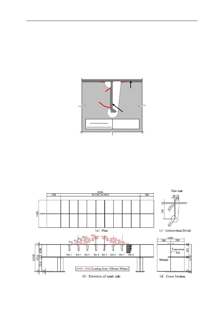
2007). Fatigue cracks are classified into 4 types, as shown in Figure 1 (Tabata et al. 2007).
At the intersection of the bulb rib and the transverse rib, the crack that propagates from
the weldment of the lower part of the slit into the transverse rib web is d-type, and the other
1276
Yamaoka D. i inni: Effect of reinforcing method against fatigue cracking of orthotropic…
that propagates from the weldment of the upper part of slit into the deck plate is a-type.
These cracks may propagate into the deck plate and have a bad influence on traffic.
It is important, therefore to grasp such fatigue cracking behaviour. An effective method
against the fatigue cracks is needed. In this study, we tried to grasp fatigue cracking
behaviour in the welded joints between the bulb rib and the transverse rib by means
of fatigue tests of the orthotropic steel deck specimen which is the same size and has
the same structural detail as the actual bridge.
Also, we verified the effect of the proposed
reinforcing method using angle steels.
a
b
c
d
Transverse
Rib
Bulb Rib
Deck Plate
a 10.6%, d 89.1%
c+d 0.3%
Percentage of
fatigue crack types
Figure 1. Fatigue cracks in welded joint between bulb rib and transverse rib in the Hanshin Expressway
2. Experimental method
2.1 Specimen
Figure 2 shows configurations and dimensions of the specimen. In this study, the object
is A bridge consisting of orthotropic steel deck, bulb ribs and transverse ribs. We produced
a specimen which has the same structural detail as the bridge. It has 8 bulb ribs and a trans-
verse rib, and is 1m long, 4m wide and 1m high.
Figure 2. Configurations and dimensions of the specimen
Konstrukcje mostowe
1277
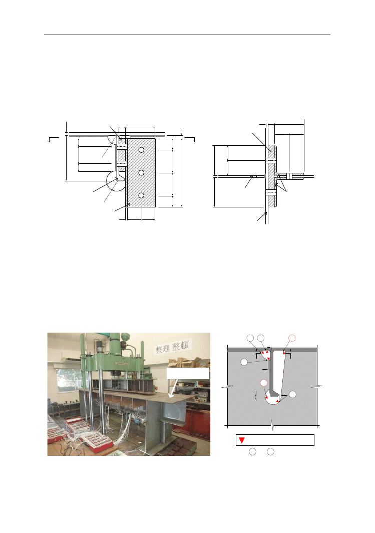
2.2 Reinforcing method
In order to reduce shearing deformation of the slit at the intersection of bulb rib
and transverse rib, angle steels (9×130×130 mm) as reinforcing members are applied
to the face and back of the transverse rib, and to the slit side of the bulb rib, using high-ten-
sile bolts. Figure 3 shows the intersection of the bulb rib and the transverse rib after applying
angle steels (Tabata et al. 2007).
R
=3
5
28
61
5
0
3
0
0
1
5
60
9
1
0
0
1
0
0
5
0
R
=3
0
2
0
0
1
2
Unit mm
Bulb Rib
Filler Plate
Angle steel
130
7
5
3
5
3
5
A
A
1
3
0
1
3
0
9
6
5
6
5
65
65
130
28
10
Transverse
Rib
9×130×130×300
9×130×130×300
28×145×270
28×145×270
(a) Elevation
(b) A-A Plan
Angle steel
Filler Plate
Bulb Rib
Figure 3. Intersection of bulb rib and transverse rib with angle steel reinforcements
2.3 Static loading test method
Figure 2 shows the 5 loading locations of the static loading test. Loading locations from
D-1 to D-4 simulate two sets of double tires with 4 rubber plates (40×200×200 mm).
Loading location D-5 simulates a set of double tires with 2 rubber plates. The load is 200kN.
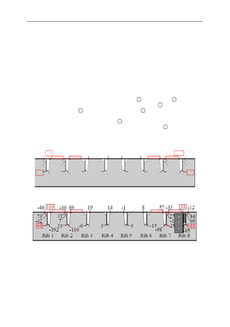
Photo 1 shows the test set-up. Figure 4 shows the locations of strain gages. By using strain
gages, we measured local stresses at the slits of the intersection of the bulb ribs and
the transverse rib.
Specim
1
10
2
5
5
5
5
5.5
3
4
5
6
Unit mm
Uniaxial Strain Gage
Only 4 and 6 : Rib 3, 4, 5, 6
Photo 1. Loading test set-up
Figure 4. Locations of strain gages
1278
Yamaoka D. i inni: Effect of reinforcing method against fatigue cracking of orthotropic…
2.4 Fatigue test method
The loading pattern of the fatigue test is D-1 (see Figure 2). In the static loading test,
we found that the stress of Rib 8 was higher than that of Rib 1. Therefore, we reinforced
the intersection of Rib 8 and the transverse rib before the fatigue test. And, we tried to grasp
the behaviour of fatigue cracking at Rib 1, and to verify the effect of reinforcing
the intersection of Rib 8 and the transverse rib. The load range was 280kN and the loading
rate was 3Hz.
3. Experimental results
3.1 Static loading test results
Figure 5 shows the results of the static loading test, both with and without reinforcing.
As shown in Figure 6, both stresses at both the upper part(
6
) and lower part(
4
) of the Rib 1
and Rib 8 slits were tensile stresses, and the stress at the upper part(
6
) of the slit is higher
than that at its lower part(
4
). The stress at the upper part(
6
) of the Rib 8 slit was higher
than that for Rib 1. Therefore, we reinforced the intersection of Rib 8. After applying angle
steel reinforcement, the stress at the upper part(
6
) of the Rib 8 slit decreased to approxima-
tely 30% (from 127 MPa to 38 MPa), and the stress of the lower part(
4
) of the Rib 8 slit
changed from a 26 MPa tensile stress to a 86 MPa compressive stress. The stress at the upper
and lower parts of the Rib 1 slit did not change.
Rib 1
-41
61
71
98
-44
-186
7
11
30
67
-35
-107
-14
26
59
127
-44
-190
0
-6
30
67 -34
-105
13
3
18
-6
3
-1
10
-11
Rib 2
Rib 3
Rib 4
Rib 5
Rib 6
Rib 7
Rib 8
Loadind Location: D-1 P = 200 kN, Unit: MPa
(a) Without reinforcing
Loadind Location: D-1 P = 200 kN, Unit: MPa
(b) With reinforcing
Figure 5. Result of static loading test
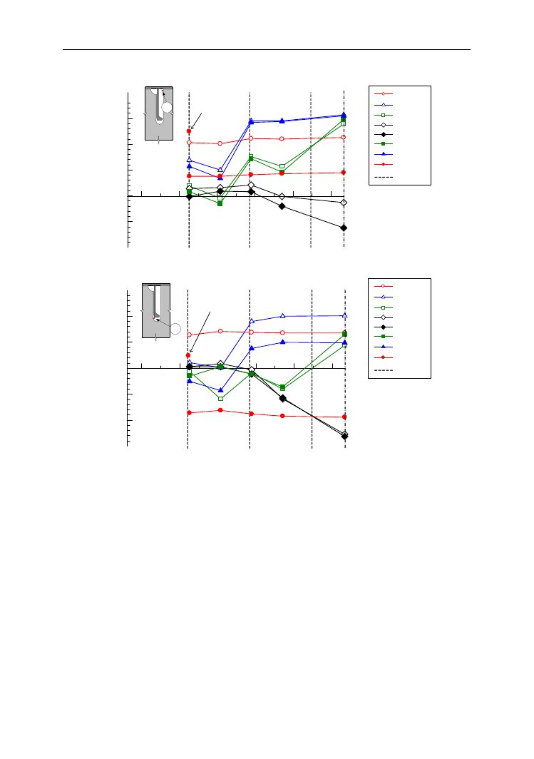
Figure 6 shows stress at the intersection of the bulb rib and the transverse rib. The stresses
at the slit of Rib 1 and Rib 8 were almost constant. As loading the slit side, the tensile
stresses at Rib 2, Rib 3, Rib 6 and Rib 7 slits increased. On Rib 4 and Rib 5, however,
the compressive stresses of Rib4 and Rib5 slits increased. Also, we found that the tensile
stress at the upper part of the slit is higher than that at its lower part.
Konstrukcje mostowe
1279
6
-100
-50
0
50
100
150
200
400
600
800
1000
1200
1400
CL
S
tr
es
s
at
U
p
p
e
r
P
ar
t
o
f
S
li
t
σ
(M
P
a)
Without Reinforcing
Distance from Edge of
Specimen to Center of
Loading Area (mm)
Rib Position
Rib 3
Rib 1
Rib 2
Rib 8
Rib 7
Rib 6
Rib 5
Rib 4
(a) Upper part of slit
4
400
600
800
1000
1200
1400
-150
-100
-50
0
50
100
150
C
L
Without Reinforcing
Distance from Edge of
Specimen to Center of
Loading Area (mm)
S
tr
es
s
at
L
o
w
e
r
P
ar
t
o
f
S
li
t
σ
(M
P
a)
Rib Position
Rib 3
Rib 1
Rib 2
Rib 8
Rib 7
Rib 6
Rib 5
Rib 4
(b) Lower part of slit
Figure 6. Stress at intersection of bulb rib and transverse rib (P=200kN)
3.2 Fatigue test results
A fatigue crack of 14 mm length was detected on the weldment of the upper part
of the Rib 1 slit after 0.7 Mcycles loading. Photo 2 shows the fatigue crack at this upper part
of the Rib 1 slit after 0.7 Mcycles loading. It was initiated at the weld toe of the upper part
of the Rib 1 slit, and propagated from the weldment into the deck plate. After 5.4 Mcycles
loading, it propagated to about 30 mm length, as shown in Photo 3.
No fatigue cracking was observed at the intersection of Rib 8 and the transverse rib,
which had applied angle steel reinforcement, after 5.4 Mcycles loading. Therefore, it was
confirmed that the fatigue crack detection life of the welded joint between the bulb rib and
the transverse rib had been improved more than eight times by applying angle steel reinfor-
cement. We then removed the angle steels applied to the intersection of Rib 8 and
the transverse rib. Without the angle steels, a fatigue crack of 2 mm length was observed on
the weldment of the upper part of the Rib 8 slit after 0.1 Mcycles loading. Photo 4 shows the
fatigue crack at the upper part of the Rib 8 slit after 0.1 Mcycles loading without angle steels.

1280
Yamaoka D. i inni: Effect of reinforcing method against fatigue cracking of orthotropic…
Lower surface of
deck plate
Weldment
Transwerse rib
Slit
Fatigue crack
14 mm
Lower surface of
deck plate
Weldment
Slit
Transwerse rib
Fatigue crack
9 mm
(a) South side
(b) North side
Photo 2. Fatigue crack at upper part of Rib 1 slit after 0.7 Mcycles loading
Lower surface of
deck plate
Weldment
Transwerse rib
Fatigue crack
29 mm
Lower surface of
deck plate
Weldment
Transwerse rib
Fatigue crack
31 mm
(a) South side
(b) North side
Photo 3. Fatigue crack at upper part of Rib 1 slit after 5.4 Mcycles loading
Lower surface of
deck plate
Weldment
Transwerse rib
Slit
Fatigue crack
2 mm
Lower surface of
deck plate
Weldment
Transwerse rib
Slit
Fatigue crack
1 mm
(a) South side
(b) North side
Photo 4. Fatigue crack at upper part of Rib 8 slit after 0.1 Mcycles loading without angle steels
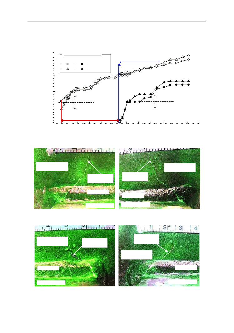
Figure 7 shows the relationship between the fatigue crack length and the number of loading
cycles. The vertical axis represents the fatigue crack length, while the horizontal axis repre-
sents the number of loading cycles. Fatigue cracks of Rib 1 and Rib 8 continued to propagate
slowly after propagating into the deck plate. After 11.1 Mcycles loading, the fatigue cracks
of Rib 1 and Rib 8 propagated to about 40 mm and 25 mm length, respectively, but they did
not propagate to the upper surface of the deck plate. Photo 5 and 6 show the fatigue cracks
Konstrukcje mostowe
1281
at the upper part of the slit after 11.1 Mcycles loading. Fatigue cracks were not observed
in other welded joints between the bulb ribs and the transverse rib.
0
1
2
3
4
5
6
7
8
9
10
11
12
0
10
20
30
40
Rib 1
Rib 8
South side
North side
Fatigue crack length
Deck plate
Weldment
Fatigue crack detection life
is 8 times
5.4Mcycles
Remove angle steels of Rib8
Deck plate
Weldment
F
at
ig
u
e
C
ra
ck
L
en
g
th
a
[
m
m
]
Number of Loading Cycles N [Mcycle]
Figure 7. Relationship between fatigue crack length and the number of loading cycles
Lower surface of
deck plate
Weldment
Transwerse rib
Fatigue crack
40 mm
Lower surface of
deck plate
Weldment
Transwerse rib
Fatigue crack
42 mm
(a) South side
(b) North side
Photo 5. Fatigue Cracks at Upper Part of Rib 1 Slit after 11.1 Mcycles loading
Lower surface of
deck plate
Weldment
Transwerse rib
Fatigue crack
24 mm
Lower surface of
deck plate
Weldment
Transwerse rib
Fatigue crack
14 mm
(a) South side
(b) North side
Photo 6. Fatigue Cracks at Upper Part of Rib 8 Slit after 11.1 Mcycles loading

1282
Yamaoka D. i inni: Effect of reinforcing method against fatigue cracking of orthotropic…
4. Conclusions
4.1 Static loading test results
1. In the case of loading the slit side of the bulb rib, the tensile stresses occurred at the upper
and lower parts of the slit of the intersection of the bulb rib and the transverse rib.
2. By applying angle steel reinforcement to the slit side of the bulb rib, the stress at the upper
part of the slit decreased to approximately 30% (from 127 MPa to 38 MPa), and the stress
at the lower part of the slit changed from a tensile stress(26 MPa) to a compressive stress
(-86 MPa).
4.2 Fatigue test results
1. Fatigue cracks were initiated at the weld toe of the upper part of the slit and propagated
through the weldment into the deck plate. After propagating into the deck plate, fatigue
cracks continued to propagate slowly.
2. It was confirmed that the fatigue crack detection life of the welded joint between the bulb
rib and the transverse rib was improved more than eight times by applying angle steel
reinforcement.
References
1. Committee of JSCE on steel structures.: The report of investigation and study subcommittee
on thick plate welded joints: 155-157, 2007,
(in Japanese).
2. Tabata S., Yamamura K., Hamada N., Sakota H., Sakai Y. and Sakano M.: Experimental study
on the reinforcing method against fatigue damage at the welded joint between bulb rib and trans-
verse rib in orthotropic steel decks, Proceedings of the 62
nd
Annual Meeting of JSCE, I-003, 2007,
(in Japanese).
Wyszukiwarka
Podobne podstrony:
Zieliński, Marek i inni Effects of Constant Magnetic Field on Electrodeposition of Co W Cu Alloy (2
Makówka, Agnieszka i inni Treatment of chronic hemodialysis patients with low dose fenofibrate effe
Synergistic Fungistatic Effects of Lactoferrin in Combination with Antifungal Drugs against Clinical
Glińska, Sława i inni The effect of EDTA and EDDS on lead uptake and localization in hydroponically
Abstract Synergistic Antifungal Effect of Lactoferrin with Azole Antifungals against Candida albican
160521 Effect of storage methods on willow chip quality BB1
Effect of storage methods on willow chip quality BB1
11 Nagao Y i inni Steel plate pre stressing reinforcement for coped steel girder ends
160523 Effect of storage methods on willow chip quality BB1
160602 Effect of storage methods on willow chip quality
05 Yamaoka D i inni Fatigue test of an urban expressway steel girder bridge constructed in 1964
Kowalczyk Pachel, Danuta i inni The Effects of Cocaine on Different Redox Forms of Cysteine and Hom
Effect of various drying methods on texture and color of tomato halves (Gholam Reza Askari, Zahra Em
Effect of long chain branching Nieznany
Effect of Kinesio taping on muscle strength in athletes
53 755 765 Effect of Microstructural Homogenity on Mechanical and Thermal Fatique
Effect of File Sharing on Record Sales March2004
31 411 423 Effect of EAF and ESR Technologies on the Yield of Alloying Elements
21 269 287 Effect of Niobium and Vanadium as an Alloying Elements in Tool Steels
więcej podobnych podstron