Micro Application Example
Autarkic switching in GAMMA instabus EIB-
network in building service applications
(with LOGO! and EIB module)
Micro Automation Set 8

Note
Micro Automation Set 8
Entry-ID 21688364
V1.1 22.08.2006
2/15
C
opyr
ight
©
Si
em
ens
AG 2
006
Al
l r
ights r
e
s
e
rv
ed
Set8
_D
ocTec
h
_v1
d
1_
en.d
o
c
Note
The Micro Automation Sets are not binding and do not claim to be complete
regarding configuration, equipping and any eventuality. The Micro Automation
Sets do not represent customer-specific solutions. They are only intended to
provide support for typical applications. You are responsible for ensuring that
the described products are correctly used. These Micro Automation Sets do not
relieve you of the responsibility of safely and professionally using, installing,
operating and servicing equipment. When using these Micro Automation Sets,
you acknowledge that Siemens cannot be made liable for any damage/claims
beyond the liability clause described.
We reserve the right to make changes to these Micro Automation Sets at any
time without prior notice. If there are any deviations between the
recommendations provided in these Micro Automation Sets and other Siemens
publications – e.g. Catalogs – the contents of the other documents have priority.
Warranty, liability and support
We do not accept any liability for the information contained in this document.
Any claims against us – based on whatever legal reason – resulting from the
use of the examples, information, programs, engineering and performance data
etc., described in this Micro Automation Set shall be excluded. Such an
exclusion shall not apply in the case of mandatory liability, e.g. under the
German Product Liability Act (“Produkthaftungsgesetz”), in case of intent, gross
negligence, or injury of life, body or health, guarantee for the quality of a
product, fraudulent concealment of a deficiency or breach of a condition which
goes to the root of the contract (“wesentliche Vertragspflichten”). However,
claims arising from a breach of a condition which goes to the root of the contract
shall be limited to the foreseeable damage which is intrinsic to the contract,
unless caused by intent or gross negligence or based on mandatory liability for
injury of life, body or health. The above provisions do not imply a change in the
burden of proof to your detriment.
Copyright© 2006 Siemens A&D. It is not permissible to transfer or copy
these Application Examples or excerpts of them without prior
authorization from Siemens A&D in writing.

Foreword
Micro Automation Set 8
Entry-ID 21688364
V1.1 22.08.2006
3/15
C
opyr
ight
©
Si
em
ens
AG 2
006
Al
l r
ights r
e
s
e
rv
ed
Set8
_D
ocTec
h
_v1
d
1_
en.d
o
c
Foreword
Micro Automation Sets are fully functional and tested automation
configurations based on A&D standard products for easy, fast and
inexpensive implementation of automation tasks in small-scale automation.
Each of these Micro Automatic Sets covers a frequently used subtask of a
typical customer problem in the low-end range.
The sets help the customer to obtain answers with regard to required
products and the question how they function when combined.
However, depending on the system requirements, a variety of other
components (e.g. other CPUs, power supplies, etc.) can be used to
implement the functionality on which this set is based. Please refer to the
respective SIEMENS A&D catalogs for these components.
The Micro Automation Sets are also available by clicking the following link:
http://www.siemens.de/microset
Table of Contents
Hardware and Software Components ........................................................... 7
Configuring the Startup Software ............................................................... 10
Foreword
Micro Automation Set 8
Entry-ID 21688364
V1.1 22.08.2006
4/15
C
opyr
ight
©
Si
em
ens
AG 2
006
Al
l r
ights r
e
s
e
rv
ed
Set8
_D
ocTec
h
_v1
d
1_
en.d
o
c
Fields of application
In conventional electric installation a separate line is necessary for each
function and a separate network for each controlling system. The instabus
EIB on the other hand, allows for controlling, monitoring, and reporting all
operational functions and processes via a joint line.
The EIB expansion module makes LOGO! a complete node within instabus
EIB. This enables connecting conventional components (more cost
efficiently) with the instabus EIB via LOGO!.
Application areas in detail:
▪ Interior
installations
▪
Building services automation
Benefit
• LOGO! can be networked with LOGO! EIB/KNX module
• With LOGO!, classic switches can be used at the instabus EIB which
saves costs
• The LOGO! functionality can be expanded with instabus EIB function
components:
▪ Many building service tasks can be solved with LOGO!
▪ Expansion of sensor options
• LOGO! also functions at instabus EIB failure
• Modifying the LOGO! parameterization/configuration also possible
without PC
• Time/data synchronization, LOGO! as master or slave in the
instabus EIB
Structure
Micro Automation Set 8
Entry-ID 21688364
1 Structure
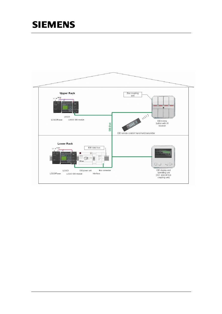
The configuration of Micro Automation Set 8 is shown in the figure below.
Figure
1-1
V1.1 22.08.2006
5/15
C
opyr
ight
©
Si
em
ens
AG 2
006
Al
l r
ights r
e
s
e
rv
ed
Set8
_D
ocTec
h
_v1
d
1_
en.d
o
c
Structure
Micro Automation Set 8
Entry-ID 21688364
Figure
1-2
V1.1 22.08.2006
6/15
C
opyr
ight
©
Si
em
ens
AG 2
006
Al
l r
ights r
e
s
e
rv
ed
Set8
_D
ocTec
h
_v1
d
1_
en.d
o
c
Hardware and Software Components
Micro Automation Set 8
Entry-ID 21688364
V1.1 22.08.2006
7/15
C
opyr
ight
©
Si
em
ens
AG 2
006
Al
l r
ights r
e
s
e
rv
ed
Set8
_D
ocTec
h
_v1
d
1_
en.d
o
c
2
Hardware and Software Components
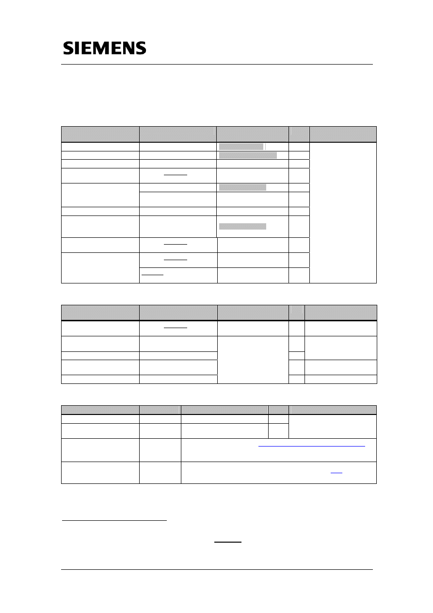
Products
Component
Type
MLFB / Order
information
No.
Manufacturer
Power supply
LOGO!Power 24 V/1.3 A
6EP1331-1SH02
2
Logic module
LOGO! 12/24 RC
6ED1052-1MD00-0BA5
1
2
Communication module
LOGO! CM EIB/KNX
6BK1700-0BA00-0AA1
2
Power supply for EIB
GAMMA instabus EIB-
power supply
5WG1 125-1AB21
1
UP 235+IR, 4-fach
5WG1 235-2AB11
1
1
Button with IR receiver
Bus coupling unit for
buttons
5WG1 114-2AB02
Remote control
For IR button
5WG1 425-7AB21
1
Display and operating unit
(incl. special bus coupling
unit)
UP 585
5WG1 585-2AB11
1
1
Interface
GAMMA instabus EIB
interface RS232
5WG1148-1AB02
1
GAMMA instabus EIB data
bus 190/01
, 214mm
5WG1190-8AB01
1
Data bus with separate
connectors
instabus EIB connector
REG 191/11 2X2fold
5WG1191-5AB11
1
SIEMENS A&D
Accessories
Component
Type
MLFB / Order
information
No.
Manufacturer
Low voltage terminal
GAMMA instabus EIB bus
terminal
5WG1193-8AB01
1
SIEMENS A&D
Connection cable
Serial connection cable,
assignment 1:1
1
Batteries for remote control
Mignon (LR03/AAA 1.5V)
4
e.g. Reichelt Elektronik
Hat rail for LOGO!- and EIB
components
TH35-7,5
2
according to DIN EN50022
2
EIB bus line
YCY 2x2x0,8 green R/100
SPECIALIST DEALER
Configuration software/tools
Component
Type
MLFB / Order information
No.
Manufacturer
LOGO! Soft Comfort
V5.0
6ED1058-0BA01-0YA0
1
Connection cable LOGO!
PC/PG
LOGO cable
6ED1057-1AA00-0BA0
1
SIEMENS A&D
EIB ETS Professional 3
V3.0d
Everything about ETS under
http://www.konnex.org/knx-tools/ets/intro/
The software itsself is free of charge. You need a chargeable licence,
however.
Product data of the
Siemens EIB components
used
For the complete Siemens ETS 3 product database click
e.
(http://www.automation.siemens.com/et/gamma/html_00/support/ets3.htm)
1
available in different services/versions
2
When using a deep top hat rail (TH35-15) the instabus EIB data rail 190/03, 214mm, MLFB
5WG1190-8AB03 has to be used.

Hardware and Software Components
Micro Automation Set 8
Entry-ID 21688364
V1.1 22.08.2006
8/15
C
opyr
ight
©
Si
em
ens
AG 2
006
Al
l r
ights r
e
s
e
rv
ed
Set8
_D
ocTec
h
_v1
d
1_
en.d
o
c
Note
1. A PG (e.g. field PG) or a PC with free serial interface is required for running
configuration software and tools!
2. The data of the EIB products used in this Micro Automation Set are already
contained in the EIB project file (see 4.2 Download of the startup code). You
must not load and import them one by one via the above link.
Function Principle
Micro Automation Set 8
Entry-ID 21688364
3 Function
Principle
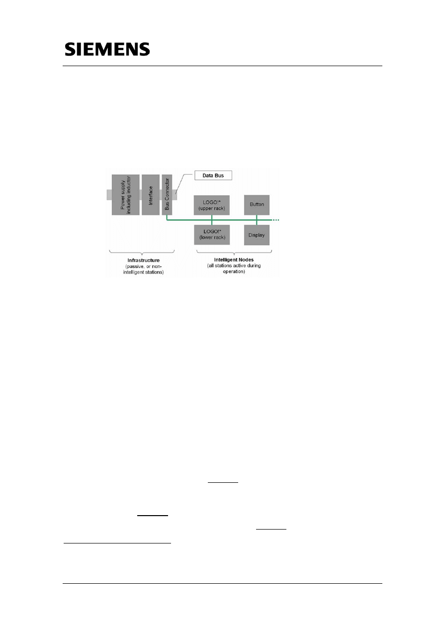
The devices in the EIB configuration can be roughly divided into two
groups, see graphic below:
• passive, or non-intelligent nodes
• intelligent nodes
V1.1 22.08.2006
9/15
C
opyr
ight
©
Si
em
ens
AG 2
006
Al
l r
ights r
e
s
e
rv
ed
Set8
_D
ocTec
h
_v1
d
1_
en.d
o
c
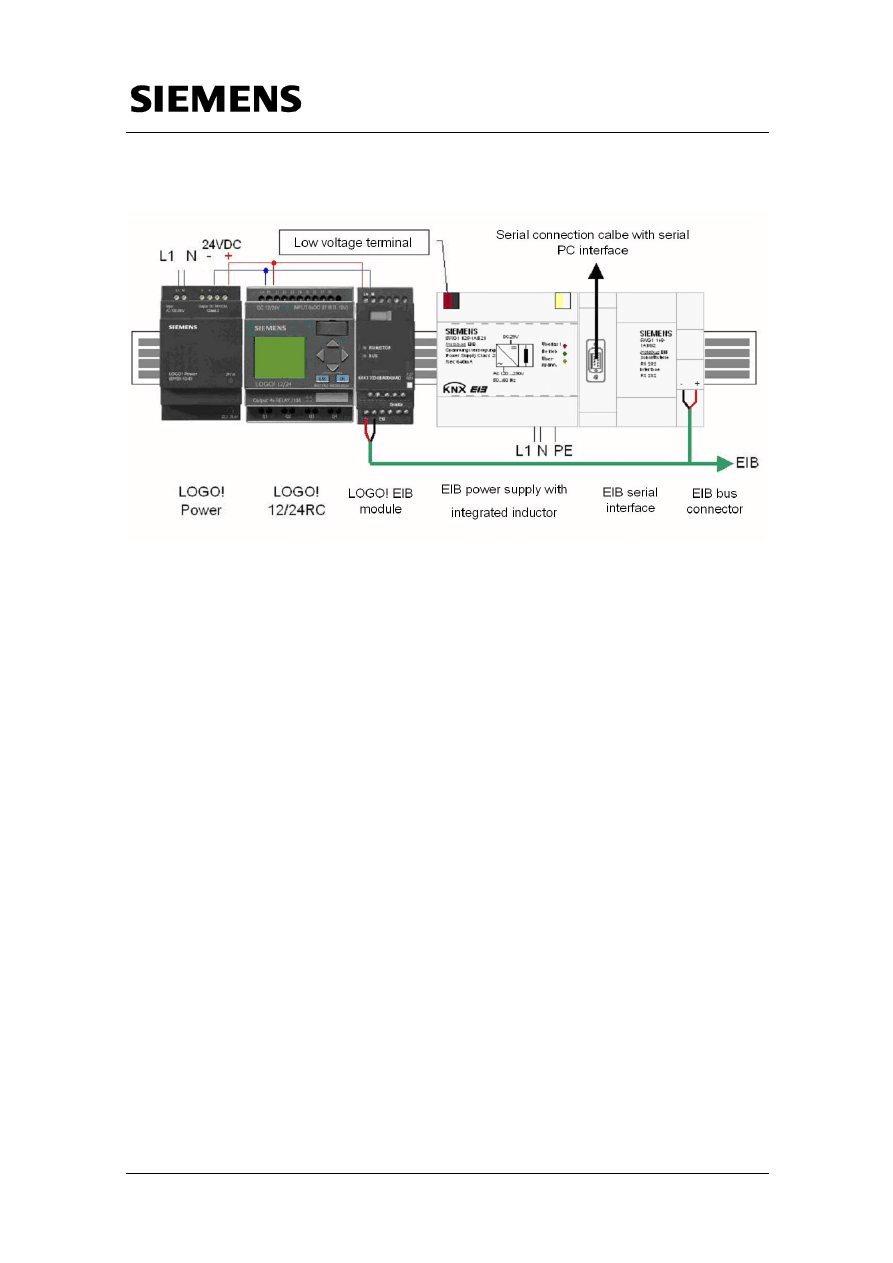
▪ Power supply with integrated inductor
(Power supply of the bus with 29V, inductor for preventing reflections at the cable
ends)
▪ Interface
(Communication interface between EIB devices and PC)
▪ Bus
connector
(Connection between EIB data bus and interior installation)
▪ Data
bus
(Back pane bus for power supply, interface and bus connector)
▪ Push button with IR receiver and IR remote control
▪ Display and operating unit
▪ LOGO! (upper rack)
▪ LOGO! (untere Etage)
*
The bus connection between the individual devices enables their inter-
communication, and control commands (e.g. On/Off), process values (e.g.
temperature) and date/time can be exchanged with other EIB devices, for
example:
▪ Using the GAMMA instabus EIB display and operating units as a
separate display for visualization (and operating) for LOGO!
▪ Communication of distributed LOGO!s with each other via GAMMA
instabus EIB
▪ Switching of LOGO! Outputs via instabus EIB message frames
*
LOGO! Here means a LOGO! Configuration with LOGO! Power, LOGO! Logic module and
LOGO! EIB communication processor.
Configuring the Startup Software
Micro Automation Set 8
Entry-ID 21688364
V1.1 22.08.2006
10/15
C
opyr
ight
©
Si
em
ens
AG 2
006
Al
l r
ights r
e
s
e
rv
ed
Set8
_D
ocTec
h
_v1
d
1_
en.d
o
c
4
Configuring the Startup Software
4.1 Preliminary
Remark
For the startup we provide software examples with test code and test
parameters as download. The software examples support you during the
first steps and tests with your Micro Automation Sets. They enable quick
testing of the hardware and software interfaces between the products
described in the Micro Automation Sets.
The software examples are always assigned to the components used in the
set and show their basic interaction. However, they are not a real
application in the sense of a technological problem solution with definable
properties.
4.2
Download of the startup code
The software examples are available on the HTML page from which you
downloaded this document.
Table
4-1
No.
File name
Contents
1
Set8_LOGO!_V1d0_en.lsc
Program for LOGO! Logic module
2 Set8_EIBproject_en.pr4
GAMMA instabus EIB configuration for
ETS 3
4.3 Configuring
Components
HW configuration and networking
Table 2:
No.
Function
Comment
1.
• Connect the products as shown in the configuration
plan to the power supply and the GAMMA instabus
EIB bus line.
Bus line:
Red wire:
Bus +
Black wire: Bus +
White wire:
Reserve
Yellow wire:
Reserve
The screening foil and drain
wire of two bus lines will not
be connected with each other.
Screening foil and drain wire
must not touch the earth
potential or any live parts.
Configuring the Startup Software
Micro Automation Set 8
Entry-ID 21688364
Configuring LOGO! with LOGO!Soft Comfort
Tabelle 3
No.
Function
Comment
1. 1
• Connect the PC and the LOGO! Logic module
with a LOGO!/PC cable via the serial interface
COM1. When using a different COM interface,
this has to be considered accordingly in LOGO!
Soft Comfort.
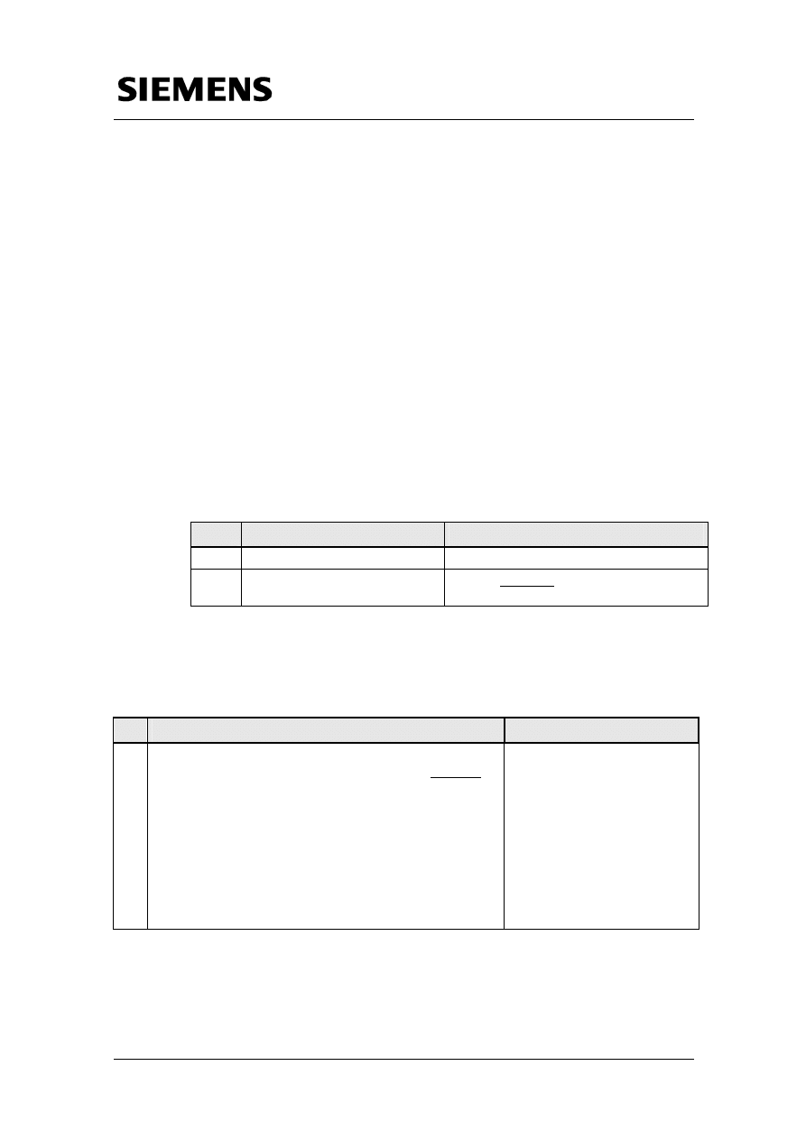
Program download via the menu
Tools>Transfer>PC->LOGO! Or the
……icon.
2.
• Open the LOGO! Program and transfer it to the
controller.
Change the Sync setting on the
LOGO! module under the menu
item „Clock“ to „On“.
3.
• Activate the LOGO! – EIB/KNX synchronisation
of the LOGO! in the upper rack (Slave).
GAMMA instabus EIB configuration for ETS 3
V1.1 22.08.2006
11/15
C
opyr
ight
©
Si
em
ens
AG 2
006
Al
l r
ights r
e
s
e
rv
ed
Set8
_D
ocTec
h
_v1
d
1_
en.d
o
c
Table 4:
No.
Function
Comment
1
• Connect the PC and the GAMMA instabus EIB
interface with a serial RS232 cable via the serial
interface COM1. Bei Verwendung einer anderen
COM-Schnittstelle, ist dies in ETS 3
entsprechend zu berücksichtigen.
Address transfer and program
download via the menu
Commissioning > Program…,
the icon, or via Program… from
the context menu of a selected EIB
station.
2
• Transfer the addresses to the intelligent EIB
stations and then load the configuration.
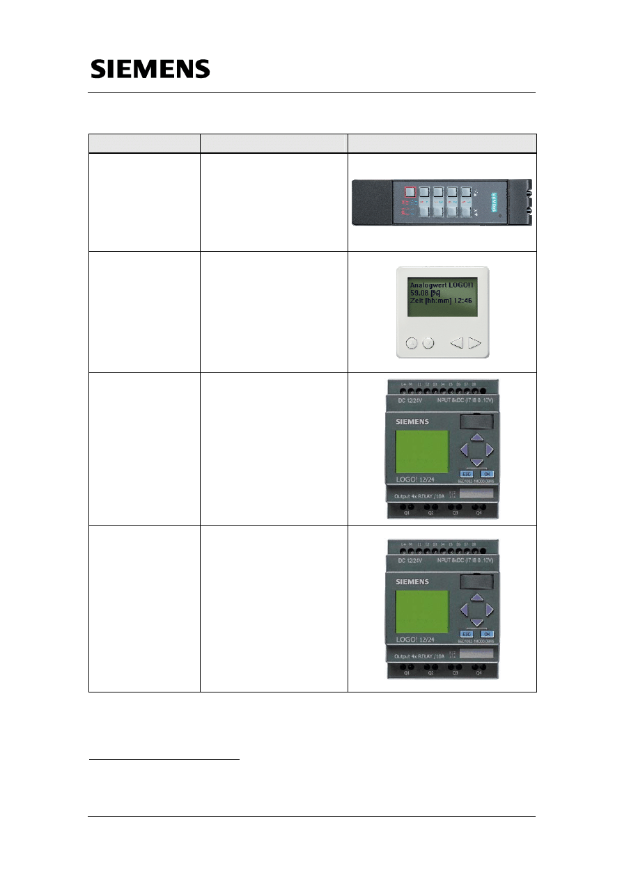
4.4 Operation
Device
Configured function
Screenshot
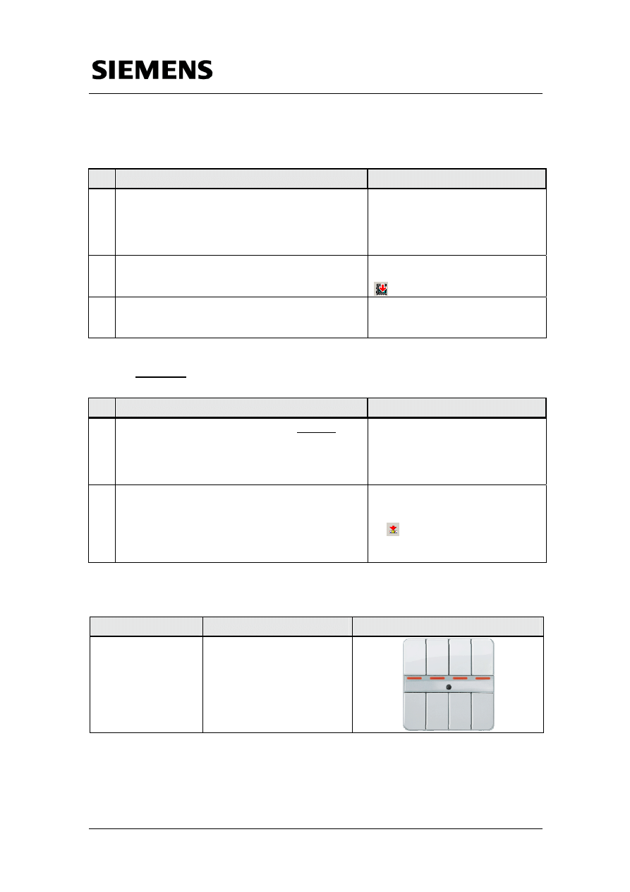
4x button with IR
(address: 6.2.3)
Buttons switch the outputs of
the LOGO!s
The LEDs show the switching
status fo the outputs Q1-Q4 of
the upper LOGO!.
LOGO! lower rack
Q1 Q2 Q3 Q4
LOGO! upper rack
Configuring the Startup Software
Micro Automation Set 8
Entry-ID 21688364
Device
Configured function
Screenshot
V1.1 22.08.2006
12/15
C
opyr
ight
©
Si
em
ens
AG 2
006
Al
l r
ights r
e
s
e
rv
ed
Set8
_D
ocTec
h
_v1
d
1_
en.d
o
c
Remote control
Buttons switch the outputs of
the LOGO!s
LOGO! Upper rack
Q4 Q3 Q2 Q1
Q4 Q3 Q2 Q1
LOGO! Lower rack
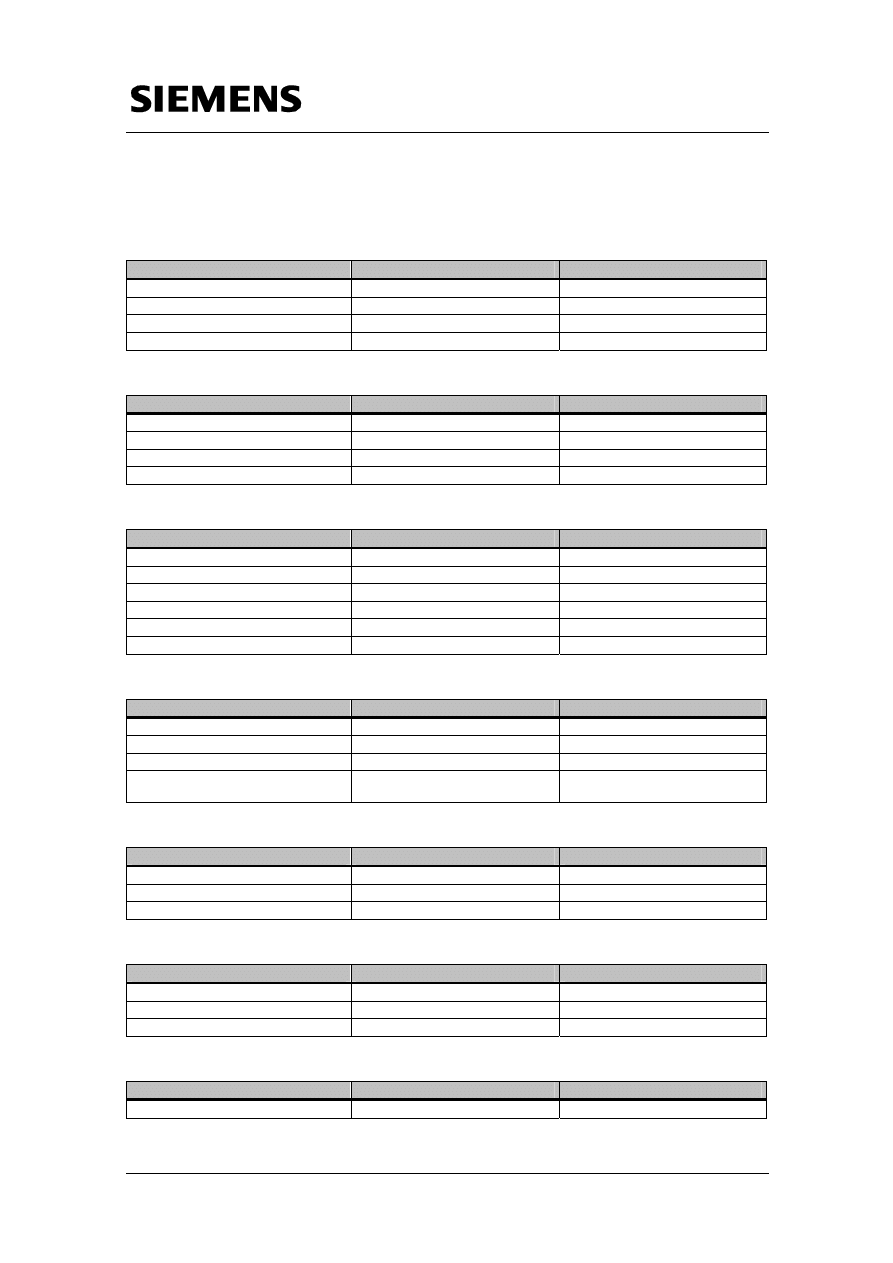
Display and operating
unit
(address: 6.2.1)
Displayed:
- Date
(LOGO!, lower rack)
- Time
(LOGO!, lower rack)
- Analog value AI1
(LOGO!, upper rack)
- Analog value AI1
∗
(LOGO!, lower rack)
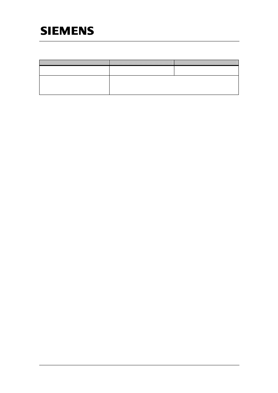
LOGO! Upper rack
(Address: 6.2.4)
Displayed:
- Date
(LOGO!, lower rack)
- Time
(LOGO!, lower rack)
- Analog value AI2 (individual)
- Analog value Al2
(LOGO!, lower rack)
Switching of:
- I1-I4 (positive edge) switch
outputs Q1-Q4
LOGO! lower rack
(Address: 6.2.2)
Displayed:
- date (individual)
- time (individual)
- Analog value AI2 (individual)
- Analog value Al2
(LOGO!, upper rack)
Switching of:
- I1-I4 (positive edge) switch
outputs Q1-Q4
- I5 switches the background
lighting of display and
operating units
∗
Display and operating unit generate an accoustic alarm if the respective analog value exceeds
99% of its final value.

Configuring the Startup Software
Micro Automation Set 8
Entry-ID 21688364
V1.1 22.08.2006
13/15
C
opyr
ight
©
Si
em
ens
AG 2
006
Al
l r
ights r
e
s
e
rv
ed
Set8
_D
ocTec
h
_v1
d
1_
en.d
o
c
Note
The LOGO! Of the lower rack (master) sends the time signal to the EIB-
Bus on the following events:
• Network
on
• hourly
• Set
Clock
• Summer/wintertime
changeover
Technical Data
Micro Automation Set 8
Entry-ID 21688364
V1.1 22.08.2006
14/15
C
opyr
ight
©
Si
em
ens
AG 2
006
Al
l r
ights r
e
s
e
rv
ed
Set8
_D
ocTec
h
_v1
d
1_
en.d
o
c
5 Technical
Data
Power supply LOGO! Power 24 V, 1.3 A
Parameter
Number/Size/Range
Comments
Supply voltage
AC 100-240V
Output voltage
DC 24V
Adjustable via potentiometer
Output current
1.3A
Dimensions (W x H x D) in mm
54 (3 TE) × 90 × 55
Logic module LOGO! 12/24 RC
Parameter
Number/Size/Range
Comments
Supply voltage
DC 12/24 V
Inputs
8 (of which 2 analog 0-10V)
Outputs
4 relays
Max. 10A
Dimensions (W x H x D) in mm
72 (4 TE) × 90 × 55
Expansion module LOGO! CM EIB/KNX
Parameter
Number/Size/Range
Comments
Supply voltage
24V (DC/AC)
-15% to 20% permissible range
Current consumption
Max. 40mA
Digital inputs max.
24
Digital outputs max.
16
Analog inputs max.
8
Dimensions
36mm x 90mm x 55mm
Weight approx. 50g
EIB Power supply
Parameter
Number/Size/Range
Comments
Supply voltage
AC 120 ... 230 V, 50/60 Hz
Output voltage
29V DC
Output current
640 mA
Dimensions
Width 4 MW (1 MW = 18 mm)
Modular device with normal
dimensions
Button with IR receiver
Parameter
Number/Size/Range
Comments
Rocker button pairs
4 =8
buttons
number of switching cycles
>20.000
Display elements
4
Remote control/ hand-held transmitter
Parameter
Number/Size/Range
Comments
Adjustable channels
8 of 64
Transmission range
Approx. 20 m
Dimensions [mm]
155 x 39 x 23
Display and operating unit
Parameter
Number/Size/Range
Comments
Number of messages
16 freely
configurable
Technical Data
Micro Automation Set 8
Entry-ID 21688364
V1.1 22.08.2006
15/15
C
opyr
ight
©
Si
em
ens
AG 2
006
Al
l r
ights r
e
s
e
rv
ed
Set8
_D
ocTec
h
_v1
d
1_
en.d
o
c
Parameter
Number/Size/Range
Comments
Number of characters per message
30 characters per line, max. 3 lines
Characters per line depending on
font
Alarm functions
• Preferred display of alarm message
• Optical display (blinking)
• Acoustic message (signal tone)
•
Accoustic feedback when pressing the button
Document Outline
- Table of Contents
- 1 Structure
- 2 Hardware and Software Components
- 3 Function Principle
- 4 Configuring the Startup Software
- 5 Technical Data
Wyszukiwarka
Podobne podstrony:
Automatyka nkf cyfrowe id 62906 Nieznany (2)
Automatyka ulog w8 id 629066 Nieznany (2)
automatyka zadania cw 3 id 7338 Nieznany
AUTOMATYKA IMG 0002 id 628983 Nieznany
automatyka10001 id 73404 Nieznany
automatyka wykl 1 id 73377 Nieznany
Automatyka i robotyzacja id 733 Nieznany
4 2 RG Automaty skonczone id 38 Nieznany (2)
automatyka id 73112 Nieznany (2)
automatyka sprawko 2 id 73363 Nieznany
automatyka c2 id 73267 Nieznany (2)
Automatyka i Robotyka id 73294 Nieznany
automaty id 72943 Nieznany (2)
automaty 3d id 72987 Nieznany (2)
Konserwator budynkow 711101 id Nieznany
Automatyka napedow id 73330 Nieznany
Automation Studio Srodowisko id Nieznany (2)
Automatyka pytania id 73347 Nieznany
więcej podobnych podstron