
MATERIAL BEHAVIOUR OF POWDER-METALLURGICALLY
PROCESSED TOOL STEELS IN TENSILE AND
BENDING TESTS
S. Marsoner, R. Ebner and R. Minichmayr
Materials Center Leoben
Franz Josef Strasse 13
8700 Leoben
Austria
F. Jeglitsch
Department of Physical Metallurgy and Materials Testing
Franz Josef Strasse 18
8700 Leoben
Austria
Abstract
The paper concentrates on the static mechanical properties of powder metal-
lurgically processed (PM) tool steels tested in tensile and bending tests. A
recently developed tensile test based on a especially designed tensile speci-
men is used to characterise the mechanical properties of a PM-tool steel in
different tempering conditions. So far there is no standard tensile testing pro-
cedure available for high strength tool steels. Main goal of the investigations
is to study the influence of heat treatment on the mechanical properties like
yield strength, ultimate tensile strength and strain to fracture. The results
of the tensile tests are compared to the results of bending tests which are
commonly used for characterising the mechanical properties of high strength
tool steels. In these tests the bending rupture strength is predicted from the
fracture load based on the assumption of a linear stress distribution within
the bending specimen. This assumption of linear elastic material behaviour
has to be recognised as the major uncertainty in the prediction of the bending
strength from the fracture load. Finite element (FE) simulations are per-
formed to model the bending test based on material properties determined in
197

198
6TH INTERNATIONAL TOOLING CONFERENCE
the tensile test. Experimental load – displacement curves are used to validate
the model.
Keywords:
tool steels, high speed steels, mechanical properties, tensile test, bending test,
finite element simulation
INTRODUCTION
High speed steels were mainly developed for cutting applications like
turning, drilling or milling. However, they are increasingly important as
tool materials for cold work applications like cold forging, blanking, cutting
or shearing because of their outstanding property profile. Besides a high
wear resistance, mechanical properties like toughness, strength and ductility
are most relevant for the application of high speed steels. Especially a high
resistance against plastic deformation in combination with a high fracture
resistance is important to realise highly loaded tools. Generally, the strength
of high speed steels is characterised by three or four point bending tests
[1, 2, 3]. Only a few results on tensile properties are reported in literature
(e.g. [4, 5]). The bending strength is calculated from the maximum load at
the onset of fracture assuming a linear stress distribution within the bending
specimen. The assumption of a linear stress distribution is in principle
invalid if plastic deformation occurs. Plasticity is sometimes indicated by
a curvature of the load deflection line, especially in case of high speed
steels tempered at higher temperatures. The rupture strength of powder
metallurgically produced high speed steels is often found to be in the range of
4000 to 5500 MPa. In many cases deviation from the linear elastic behaviour
is found on exceeding a stress level of about 2500–3500 MPa at the surface
of the bending specimen (e.g. [2, 3]). It can be thus assumed that the bending
test is suitable to get information on the material properties in case of a special
loading geometry, but it is not suitable to characterise material properties like
yield strength, ultimate tensile strength and ductility.
In the paper the mechanical behaviour of one selected powder metallurgi-
cally processed high speed steel is investigated using the recently developed
new tensile test procedure. For comparison, bending tests were additionally
performed. Finite element simulations are employed to simulate the bending
test using material data determined in the tensile test.

Material Behaviour of Powder-Metallurgically Processed Tool Steels in Tensile and...
199
Table 1.
Chemical composition of HS 10-2-5-8 (B¨ohler S390PM) in weight percent
C
Cr
W
Mo
V
Co
1,63
4,66
10,54
2,00
4,70
7,83
Table 2.
Heat treatment program of HS 10-2-5-8 (B¨ohler S390PM)
austenising
tempering, each with 3×2h
1130
◦
C/ 6 min
475
◦
C
500
◦
C
525
◦
C
550
◦
C
575
◦
C
MATERIALS, SPECIMENS AND EXPERIMENTAL METH-
ODS
A powder metallurgically processed high speed steel of the type DIN HS
10-2-5-8 (B ¨
OHLER S390PM) was investigated in this paper. The chemical
composition of this steel is summarised in Table 1. The heat treatment was
performed by austenising of the specimens in a salt bath with subsequent
quenching and three times tempering for two hours. To investigate the
influence of the heat treatment the tempering temperature was varied from
about 475 to 575
◦
C. Details on the heat treatment program are shown in
Table 2.
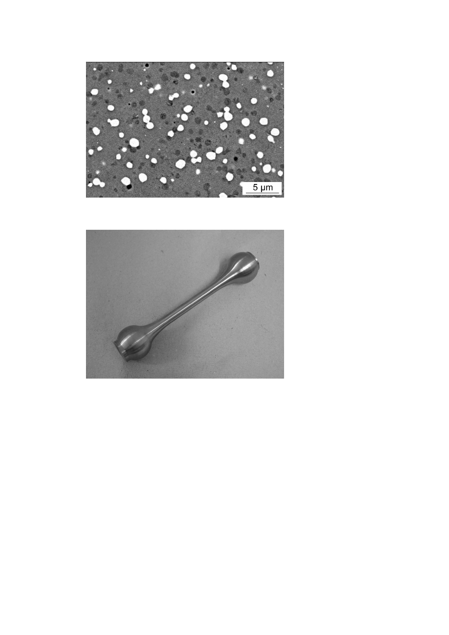
The microstructure of the fully heat treated material consisted mainly
primary carbides embedded in a tempered martensite matrix. Fig 1 shows a
scanning electron micrograph of the microstructure indicating micrometer
sized primary carbides of the types MC (grey) and M
6
C (white). The mean
size of the globular primary carbides is about 1 µm, the maximum size is
about 2,5 µm. The volume fraction of the primary carbides is about 0,15.
For details about the microstructure of high speed steels the reader is referred
to Ebner et al. [6].
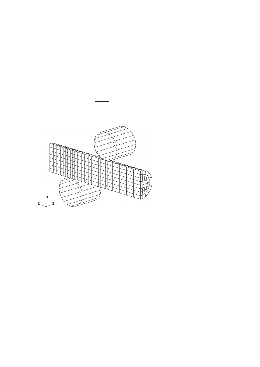
The tensile properties were determined with a new tensile specimen (
[6, 7]), which was developed to characterise the tensile behaviour of high
strength tool steels. The shape of the new tensile specimen is shown in Fig 2.
The specimen has a diameter of 8 mm and a measuring length of 40 mm.
The shape of this specimen was optimised by finite element simulation in
order to minimize stress concentrations. The specimens for the four point
200
6TH INTERNATIONAL TOOLING CONFERENCE
Figure 1.
Scanning electron micrograph of the high speed steel HS 10-2-5-8PM
Figure 2.
Shape of the new tensile specimen
bending test had a circular cross section of 5 mm and a length of 55 mm. The
Material Behaviour of Powder-Metallurgically Processed Tool Steels in Tensile and...
201
specimens were finished by grinding to a mean surface roughness of about
0,2 µm after heat treatment.
All mechanical tests were performed in an universal tensile testing ma-
chine (ZWICK UPM 1485). In the tensile tests the strain measurement was
performed by a video extensometer. The bending tests were carried out in
a four point bending set-up. The load was applied via high speed steel rolls
which were heat treated to a hardness of about 66,5 HRC. Load displacement
curves were measured and the load to fracture F
B
was used to calculate the
bending rupture strength σ
b,f
by assuming a linear elastic stress distribution
in the bending specimen (1).
σ
b,f
=
16
F
B
x
πD
3
,
(1)
where D is the diameter of the bending specimen and x the minimum hori-
zontal distance between upper and lower rolls.
Figure 3.
FE–model of the bending specimen
3D-finite element simulations were carried out using the software package
ABAQUS
®
to verify the stress and strain distributions in a bending specimen.
A three dimensional model had to be used because of the symmetry of the
bending specimen. The specimen was defined with an elastic-plastic material
202
6TH INTERNATIONAL TOOLING CONFERENCE
behaviour, the load was applied via rolls with rigid surfaces. The used FE–
model is shown in Fig 3. Main attention had to be laid on the simulation
of the contact zone between rolls and specimen. The use of rolls instead of
single forces was necessary to avoid numerical problems due to extremely
high local stresses, which would lead to very high plastic deformation in the
contact zone. Stress-strain data of the high speed steel in the various heat
treatment conditions determined with the new tensile test were used in the
FE simulation. Experimentally determined load displacement curves were
used to validate the FE model.
RESULTS AND DISCUSSION
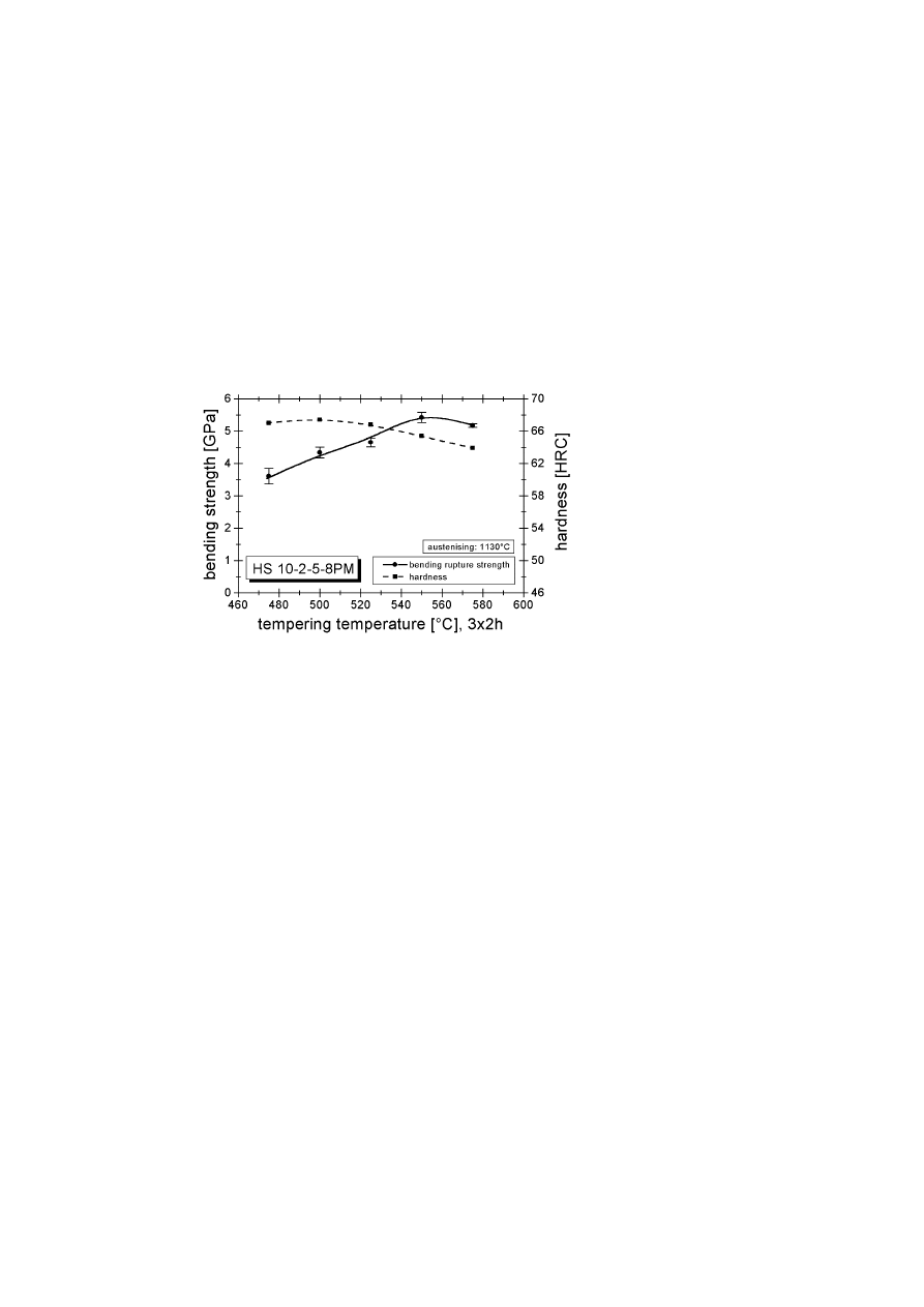
Figure 4.
Influence of tempering temperature on bending strength and hardness
The results of the mechanical tests are summarised in Fig 4 and Fig 5.
Figure 4 shows the bending strength determined by means of Equation 1 and
the hardness (Rockwell C), Fig 5 shows the yield stress, the ultimate tensile
strength and the ductility as a function of the tempering temperature. The
bending rupture strength σ
b,f
increases from about 3600 MPa at a tempering
temperature of 475
◦
Cto a maximum of about 5400 MPa at a tempering
temperature of about 550
◦
Cfollowed by a slight decrease on further increase
of the tempering temperature. In contrast the maximum hardness occurs
Material Behaviour of Powder-Metallurgically Processed Tool Steels in Tensile and...
203
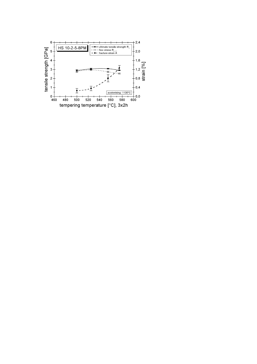
Figure 5.
Influence of tempering temperature on ultimate tensile strength, 0,2% proof
stress and fracture strain
at a tempering temperature of about 500
◦
Cfollowed by a decrease with
increasing tempering temperature. The 30 to 50
◦
Cshift in the tempering
temperatures which lead to the maximum values of the hardness and the
bending strength is in good accordance with results from literature [3]. The
results of the tensile tests indicate that the maximum tensile strength is
about 3200 MPa for a tempering temperature of about 540
◦
C, whereas the
maximum in the yield stress is achieved at a tempering temperature of about
525
◦
C. The tensile tests furthermore indicate a low but remarkable ductility
which is ranging from about 0,2% for tempering at 500
◦
Cto about 1,3%
for tempering at 575
◦
C. Scattering of the yield and tensile strength data is
higher at the lower tempering temperatures.
A comparison of bending and tensile strengths of Fig 4 and Fig 5 reveals
that the tensile strength is about 500 to 2400 MPa lower than the bending
strength. It is argued that a non-linear stress distribution within the bending
specimen caused by local plastic deformation is responsible for these differ-
ences. FE simulations are employed in order to verify this assumption. For
the FE simulations the stress–strain behaviour of the material and a suitable
fracture criterion are necessary.
204
6TH INTERNATIONAL TOOLING CONFERENCE
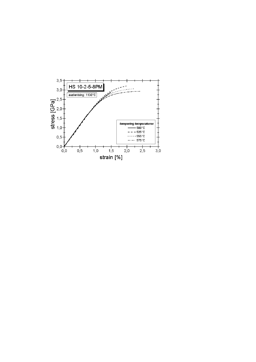
Typical stress–strain curves of investigated material subjected to different
tempering temperatures are shown in Fig 6. The results indicate that all
specimens fracture prior reaching the point of plastic instability, which is
characterised by attaining a maximum in the technical stress–strain curve
followed by a subsequent stress reduction. The plastic instability followed
by localised deformation (necking) is achieved in case of the HS 10-2-5-8
for tempering temperatures above about 600
◦
C.
Figure 6.
Effect of tempering on stress–strain behaviour
For the FE simulation of the bending test the experimental measured
stress–strain data from Fig 6 were used. It was necessary to extrapolate
the stress–strain curves to higher strain levels. The extrapolation was done
by assuming a linear stress–strain behaviour with the slope at the onset of
fracture. Main reason for this extrapolation was that higher strains occur in
the contact zone between the bending specimen and the loading cylinders.
Non-linear effects from this contact zone affect the load displacement curves
and have thus be considered in the simulation.
The validation of the FE model was performed by comparing calculated
load–deflection curves with experimentally determined ones. A comparison
of calculated and measured load-deflection curves is shown in Fig 7. Slight
differences between these two curves only occur in the region of high loads
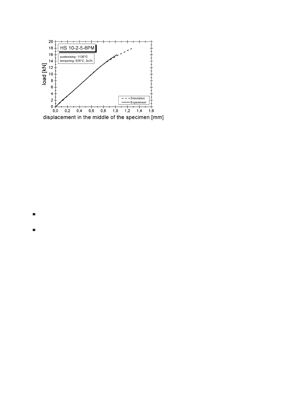
Material Behaviour of Powder-Metallurgically Processed Tool Steels in Tensile and...
205
Figure 7.
Experimental and simulated load displacement curves
which can be attributed to uncertainties resulting from the bending test, the
tensile test and the FE simulation. Despite these slight discrepancies at
higher loads it can be concluded that the results from the simulation are
in suitable accordance with the experimental results. The FE simulations
were stopped on reaching the true strain to fracture ( = fracture criterion) as
determined from the tensile tests in the outer fibre of the bending specimen.
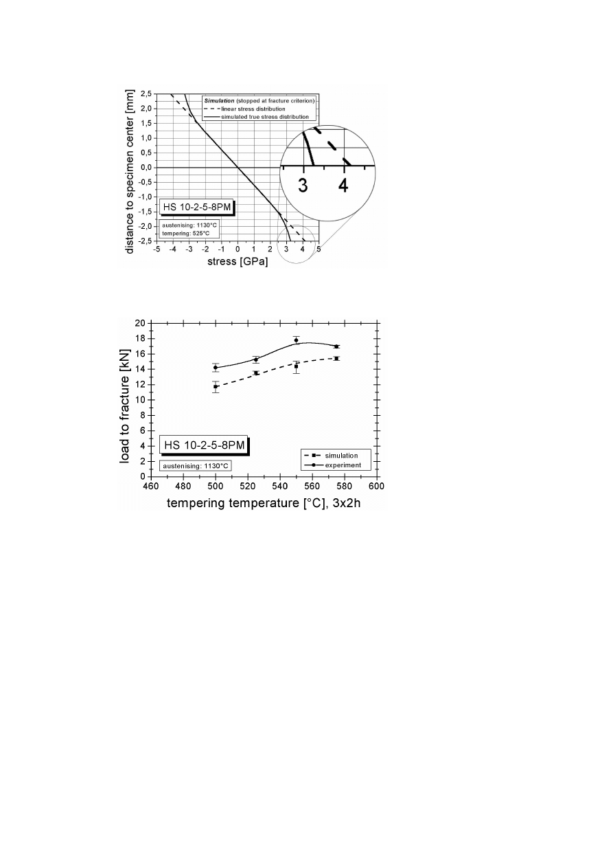
The calculated stress distribution in the bending specimen at reaching the
fracture criterion is shown in Fig 8 (solid curved line). Assuming that the
same bending moment is applied in case of a linear elastic material behaviour
this would lead to the dashed straight line.
The following conclusions can be drawn from Fig 8 :
The FE simulations reveal that a significant fraction of the cross section
is subjected to plastic deformation.
The non-linear stress distribution seems to be responsible for the sig-
nificant over-estimation of the fracture stress.
Figure 9 shows a comparison between experimentally determined and
simulated fracture loads at fracture criterion. The results indicate that the
experimentally found increase of the fracture load with increasing tempering
temperature can be well reproduced by the FE simulations but the predicted
206
6TH INTERNATIONAL TOOLING CONFERENCE
Figure 8.
Curved line: FE–simulated stress distribution; straight line: stress distribution
by assuming linear elastic material behaviour
Figure 9.
Experimental and simulated load to fracture
fracture loads are generally too low. It is argued that this effect is caused by
an underestimation of the fracture strain which was taken from the tensile

Material Behaviour of Powder-Metallurgically Processed Tool Steels in Tensile and...
207
tests. One possible reason is that the stressed volume is significantly smaller
in the bending specimens than in the tensile specimens. The probability
of finding a fracture initiating defect is thus lower in the bending specimen
which causes a higher ductility. Choosing fracture strains which are about 50
to 100% higher than those determined in the tensile tests lead to calculated
fracture loads which are comparable to the experimentally measured ones.
CONCLUSION
The aim of the paper was to study the mechanical behaviour of ledebu-
ritic tool steels especially high speed steels. Standard bending tests and
tensile tests based on a recently developed specimen and procedure were
performed. The investigated material was a PM high speed steel DIN HS
10-2-5-8 (B ¨
OHLER S390PM). Significant differences were found for the
material strengths determined in the tensile and the bending tests. In order
to understand the reasons for these differences FE simulations of the bending
tests were carried out based on material data which were determined in the
tensile test. The results of the study can be summarised as follows:
A developed tensile test (specimen and testing procedure) enables the
determination of tensile properties of fully heat treated high speed
steels.
Variations of the heat treatment reveal its strong influence on the tensile
properties.
The tensile strength values are significantly lower than the strength
determined in the bending specimen.
The FE simulations of the bending test indicate that plastic deforma-
tion takes place over a significant fraction of the cross section.
The non-linear stress distribution due to the plastic deformation is the
main reason for the significant overestimation of the strength levels in
the standard bending tests.
Good accordance between experimentally determined and calculated
fracture loads in the bending tests can be achieved by assuming that
fracture occurs at a strain which is about 50 to 100% higher than the
tensile fracture strain.

208
6TH INTERNATIONAL TOOLING CONFERENCE
The results of the present paper show that it is possible to determine
tensile properties of high strength materials quite easily. This test has the
advantage to determine clearly defined material properties which can be
used in simulations. The bending test reveals the material behaviour in case
of a special loading situation namely in a bending bar. In the bending test
not only the strength of the material is considered but also the effect of the
ductility of the material.
ACKNOWLEDGMENT
The authors would like to thank B ¨ohler Edelstahl GmbH & Co KG for
supplying with tool steels. Financial support for this work by the Tech-
nologie Impulse G.m.b.H, the County of Styria, the Innofinanz – Steirische
Forschungs- und Entwicklungsf¨urderungsges. m.b.H. and the Municipality
of Leoben in the frame of the Austrian Kplus Competence Center Program
is highly acknowledged.
REFERENCES
[1] G. HOYLE, "High speed steels" (Butterworths, London, 1988) p. 123.
[2] S. WILMES, Stahl und Eisen 81 (1961) 676.
[3] W. SCHMIDT, Thyssen Edelst. Techn. Ber. 13 (1987) 141.
[4] J. A. RESCALVO and B. L. AVERBACH, Metall. Trans. 10A (1979) 1265.
[5] P. BRØNDSTED and P. SKOV-HANSEN, Int. J. Fatigue 20 (1998) 373.
[6] R. EBNER, H. LEITNER, D. CALISKANOGLU, S. MARSONER and F. JEGLITSCH,
Z. Metallkde 92 (2001) 820.
[7] J. M. LACKNER, "Entwicklung eines Zugversuches f¨ur h¨ochstfeste Werkzeugst¨ahle",
Diploma thesis (University of Leoben, Leoben, 2001).
Wyszukiwarka
Podobne podstrony:
79 1111 1124 The Performance of Spray Formed Tool Steels in Comparison to Conventional
Investigations of White Layer Formation During Machining of Powder Metallurgical Ni Based ME 16 S
11 Fatigue behaviour of misaligned butt welded joints in the bottom flange
94 1363 1372 On the Application of Hot Work Tool Steels for Mandrel Bars
80 1125 1146 Spray Forming of High Alloyed Tool Steels to Billets of Medium Size Dimension
36 495 507 Unit Cell Models for Thermomechanical Behaviour of Tool Steels
43 597 609 Comparison of Thermal Fatique Behaviour of Plasma Nitriding
50 707 719 Thermal Fatique and Softening Behaviour of Hot Work Steels
1 3 16 Comparison of Different Characteristics of Modern Hot Work Tool Steels
16. Macierz bcg, Materiały PSW Biała Podlaska, ZiPM- ćwiczenia
16 Motywacje i emocje materialy
Powder Metallurgy
Nauka o Organizacji 16.12.2012 materiały od wykładowcy, UG 2013-2014 Zarządzanie, II rok, NOO P.Wale
EO-16 agr, WAT-materiały, saper
więcej podobnych podstron