
Investigations of White Layer Formation During
Machining of Powder Metallurgical Ni-Based
ME 16 Superalloy
S.C. Veldhuis, G.K. Dosbaeva, A. Elfizy, G.S. Fox-Rabinovich, and T. Wagg
(Submitted April 2, 2009; in revised form August 19, 2009)
Surface integrity of machined parts made from the advanced Ni-based superalloys is important for modern
manufacturing in the aerospace industry. Metallographic observations of the ME 16 alloy microstructure
were made using optical metallography and a high-resolution scanning electron microscope with energy
dispersive x-ray spectrometer (HR SEM/EDS). Tool life of cemented carbide inserts with TiAlN coating
during machining (finishing turning operation) of ME 16 superalloy has been studied and wear patterns of
the cutting tools were identified. Surface integrity of the machined part after completion of the turning
operation was investigated. The morphology of machined parts has been examined and cross-sections of the
machined surfaces have been analyzed. The formation of white layer on the surface of the machined part
was studied for varied machining conditions. It was found that a 2-4 lm thick white layer forms during
turning of the ME 16 superalloy. This layer was investigated using EDS and XRD. The studies show that
the white layer is an oxygen-containing layer with a high amount of aluminum, enriched by chromium and
tungsten. Under specific cutting conditions, the structure of white layer transforms into a c-alumina.
Formation of this thermal barrier ceramic white layer on the surface of the machined part negatively affects
its surface integrity and cutting tool life.
Keywords
aerospace, machining, metallography, superalloys
1. Introduction
Fine grain ME 16 nickel base superalloy forgings are
produced by powder metallurgy processing (PM) for aero-
space applications (Ref
). ME 16 has been recently developed
for turbine and disk applications requiring strength and creep
resistance at relatively high temperatures (600-800
°C), as well
as well as resistance to fatigue crack initiation at the lower
temperatures (300-600
°C) (Ref
). Generally, PM superal-
loys having increased processability will meet increased
temperature capability while maintaining strength and lower
density (Ref
Two major advantages accrue from making a powder
metallurgy alloy, due to the rapid solidification rates of
atomized metal droplets. The grain size of the product is very
small, of the order of microns, much smaller than in typical cast
materials (Ref
,
). Because of lack of segregations or
precipitations, powder metallurgy aerospace alloys can be
designed or tailored to contain a higher alloy content than is
possible using casting techniques. This, in turn, should
contribute to the development of alloys with still greater
strength. Also, a more uniform structure compared to cast
materials gives a better, more homogeneous distribution of the
strengthening phases throughout the powder compact and
should result in better properties (Ref
,
Machining of advanced ME 16 alloy is a significant
challenge. This is due to a more complex combination of
material properties, including lowering of thermal conductivity
that leads to elevating temperatures at the tool/chip interface
during cutting, work hardening tendency during machining that
becomes more severe with increased strengthening of this alloy,
and intensive adhesion to the surface of the tooling under
operation. Tool life can be significantly decreased (Ref
Generally, PM microstructure improvements such as absence of
large carbide particles have been accompanied by decreased
sensitivities to defects during machining (Ref
). On the
other hand, one of the key requirements for rotor blades and
discs superalloys is fatigue strength (Ref
). In order to
maintain fatigue strength, the most challenging aspects when
machining these materials come from the workpiece surface
quality point of view. For instance, formation of the white layer
poses a significant potential danger to fatigue life (Ref
). For
this material to be used in critical engine components, this issue
must be resolved first.
To date there is not much information available on the
machining of ME 16. This paper focuses on investigations of
structural characteristics of ME 16 alloy and surface integrity
issues of the machined part, with an emphasis on the features of
the white layer formation.
S.C. Veldhuis, G.K. Dosbaeva, G.S. Fox-Rabinovich, and T. Wagg,
Department of Mechanical Engineering, McMaster University, 1280
Main St. W., Hamilton, ON L8S 4L7, Canada; and A. Elfizy,
Manufacturing Engineering Development, Pratt & Whitney Canada,
1000 Marie-Victorin, Longueuil, QC J4G 1A1, Canada. Contact
e-mail: dosby@mcmaster.ca.
JMEPEG (2010) 19:1031–1036
ÓASM International
DOI: 10.1007/s11665-009-9567-7
1059-9495/$19.00
Journal of Materials Engineering and Performance
Volume 19(7) October 2010—1031
2. Experimental
In this work, the structure and machinability of the powder
metallurgical nickel-based superalloy ME 16 has been studied
in detail. Intensive studies of the ME 16 alloy microstructure,
surface morphology of the machined part and the white layer
formation have been performed using various methods includ-
ing optical metallography, x-ray diffraction (XRD) and a high-
resolution scanning electron microscope with energy dispersive
Table 1
ME 16 alloy elemental composition wt.% based
on the quantitative EDS data
Elemental content
Al
Ti
Cr
Co
W
Ta
Mo
Nb
3.1
2.6
10.4
20.5
3.0
1.4
1.3
1.4
Balance is minor amount of nickel and alloying elements
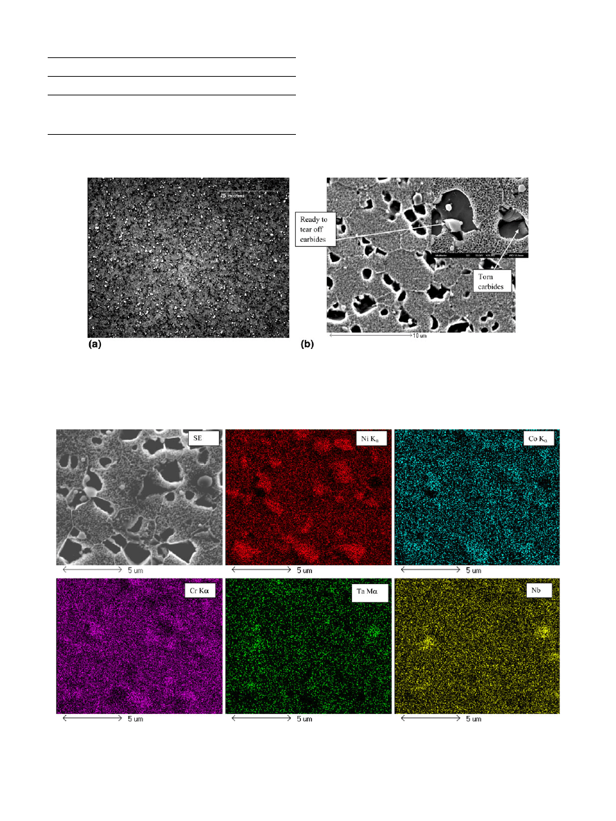
Fig. 1
Optical and SEM metallography of ME 16 alloy (workpiece material): (a) optical image, magnification 16009; (b) HR SEM image,
magnification 50009 and 200009
Fig. 2
SEM elemental map of ME 16 alloy. TaC and NbC formation
1032—Volume 19(7) October 2010
Journal of Materials Engineering and Performance
x-ray spectrometer (HR SEM/EDS). The machining experi-
ments were performed using a Boehringer VDF 180 turning
Centre. Tool life was studied under various cutting speed
conditions. The tool life was evaluated as a length of cut (m)
when flank wear of cutting insert reaches 300 lm. The
parameters of cutting used during turning experiments (finish-
ing operation) were the following: speed 30-65 m/min, depth of
cut 0.125 mm, feed 0.1225 mm/rev. Commercial cemented
carbide WC-Co inserts (K-grade) with TiAlN PVD coating,
commonly used for cutting of Inconel alloys, were employed in
this work. All the cutting tests were performed under wet
machining conditions using Commonwealth water-based cool-
ant CommCool Max.
Surface roughness measurements were carried out with a
surface roughness tester, Zygo New View 5000 interferometer
optical profiling system, using evaluation and cut-off lengths of
5 and 0.8 mm, respectively. The surface roughness was taken at
four locations (90
° apart) and repeated twice at each point on
the face of the machined surface and the average values were
reported.
3. Results and Discussion
3.1 Study of the Microstructure and Properties
The general elemental composition of the ME 16 sample is
presented in Table
. Figure
presents optical metallographic
images of the ME 16 alloy. There are evenly distributed fine-
grained carbides in the structure (Fig.
a). These carbides have
low cohesion to the matrix (Fig.
b) and were found to be
easily torn off during sample preparation (polishing and
etching). They have a complex composition. The matrix of
ME 16 is extremely fine grained with an average grain size of 7
lm (fine grains of Ni-based c-phase, Fig.
b). Figure
shows
the EDS elemental map for ME 16 alloy. The ME 16 alloy
contains fine (microns-sized) carbides, mainly (Ta, Ti, Nb) C,
within a ductile (Co, Ni, Cr) matrix phase (Ref
). The
hardness of ME 16 alloy was measured and compared to the
widely used Inconel 718 Ni-based superalloy. Hardness of both
alloys is similar: HRC 47-48 for the Inconel 718 and 46-47 for
the ME 16.
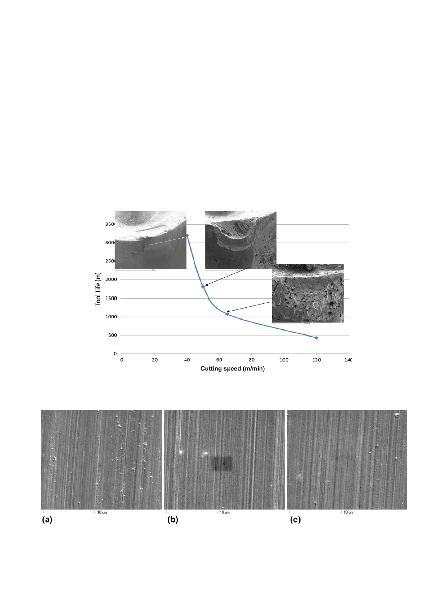
Fig. 3
Tool life and crater formation of CC inserts with TiAlN coating vs. cutting speed during machining of ME 16 alloy
Fig. 4
Surface finish of ME 16 at various cutting speeds: (a) 30 m/min, (b) 40 m/min, and (c) 50 m/min. Magnification 50009
Journal of Materials Engineering and Performance
Volume 19(7) October 2010—1033
3.2 Tool Life and Wear Behavior Studies
The tool life of cemented carbide inserts with TiAlN coating
versus cutting speed is presented in Fig.
. Tool life notably
decreased with increasing cutting speeds from 20 to 65 m/min.
Wear patterns were studied for the coated cemented carbide
inserts. Figure
presents SEM images of worn cemented
carbide inserts. Cratering of the rake surface was observed to be
significant and increased rapidly with a rise in cutting speed.
The cratering was found to be quite severe at 50 m/min and it
was catastrophic at 65 m/min. This severe diffusive wear can
be caused by high temperatures at the rake surface, which is
most likely due to the low thermal conductivity of the ME 16.
3.3 Surface Integrity Studies
The surface morphology of the machined part made of ME
16 alloy is presented in Fig.
(a)-(c). No visible defects were
detected on the surface. Surface roughness data show that the
average roughness R
a
after turning experiments (finishing
operation) are almost similar: 2.535, 2.707, and 2.668 lm
correspondingly.
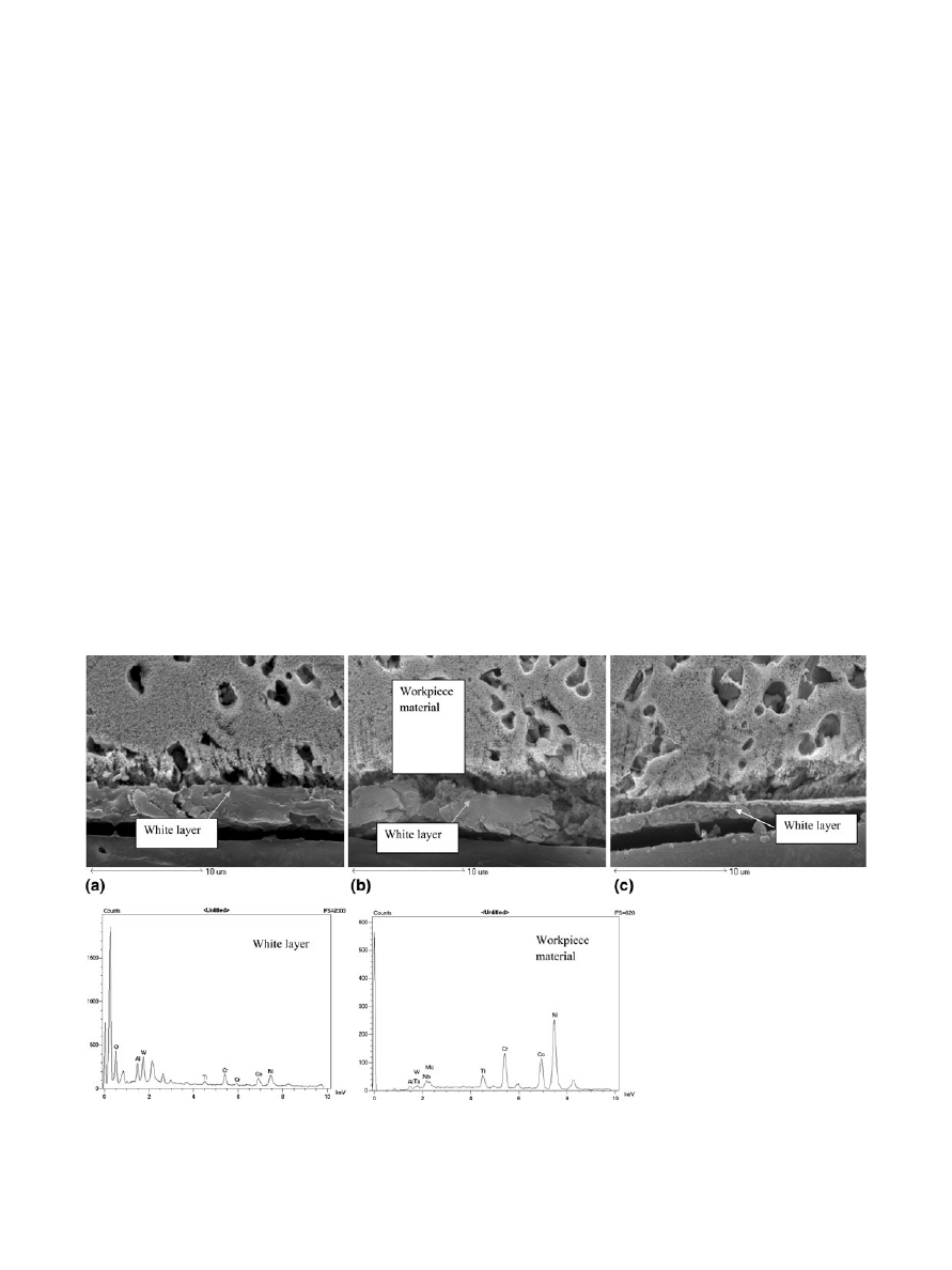
However, metallographic sections showed the machining of
the ME 16 super alloy using cemented carbide inserts with
TiAlN coating results in the formation of a white layer under
varying cutting conditions. At speeds of 30 and 40 m/min, the
white layer is thick and noncontinuous (Fig.
a, b) and its
average thickness is 4 lm. At 50 m/min, the layer is continuous
and its thickness is diminished down to 2 lm (Fig.
c). The
EDS point analysis shows that the white layer is a metal-
ceramic compound (Al-Cr-O) that forms on the surface during
machining (Fig.
). EDS elemental map confirm data of point
EDS analysis and also indicates aluminum and tungsten in this
layer (Fig.
). This layer has poor adhesion to the substrate. It is
almost flaked off in Fig.
and
.
XRD studies of the white layer formed on the surface of
machined part indicate the formation of a c-alumina phase
(see corresponding spectrum in Fig.
a) at cutting speed of
50 m/min. The c-alumina is a low-temperature modification of
a-alumina (Ref
) and its formation indicates that the
actual temperatures in the cutting zone are around 750-800
°C.
However c-alumina has similar characteristics to the a-alumina
and has a similar effect on the surface integrity of the machined
part. This undesirable phase cannot be detected by XRD at the
lower cutting speeds of 40 m/min (Fig.
b).
Alumina phase found in the white layer is ceramic and acts
as a thermal resistant layer that is formed in situ during cutting
on the machined surface of the ME 16 alloy. A significant
portion of the heat generated during cutting goes into the tool
instead of workpiece. These aspects may have encouraged
intensive cratering on the rake surface of the cutting tool
(Fig.
). In addition, the ceramic layer is extremely brittle
compared to the core. The machined part with this layer could
have reduced cycle fatigue strength due to high possibility of
crack formation within the white layer (Ref
).
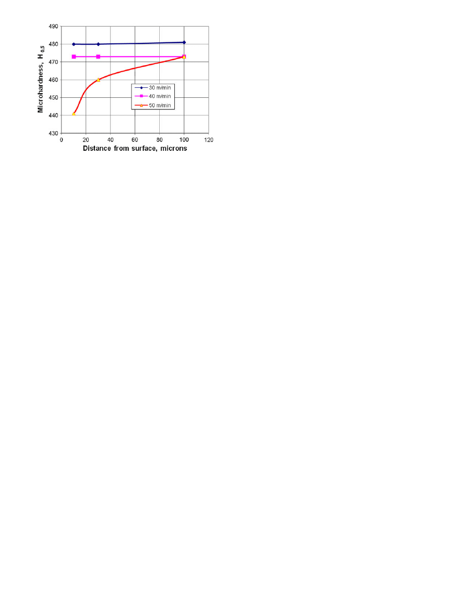
The microhardness distribution for the machined surface of
ME 16 at the cutting speeds is presented in Fig.
. The data
presented show that at cutting speeds above 40 m/min a
softening of a region close to the surface layer takes place. This
is related to the hardness of the workpiece material layer below
the superficial (2-4 lm thick), white layer (Fig.
). White layer
composed of ceramic alumina phase may prevent heat from
being evenly absorbed by the core of the machined part
(Ref
,
). This could worsen cutting conditions at the higher
cutting speed.
Fig. 5
SEM images and EDS analyses of cross-sections of machined part made of ME 16 alloy, 50009. White layer, formed at cutting speed:
(a) 30 m/min, (b) 40 m/min, and (c) 50 m/min
1034—Volume 19(7) October 2010
Journal of Materials Engineering and Performance
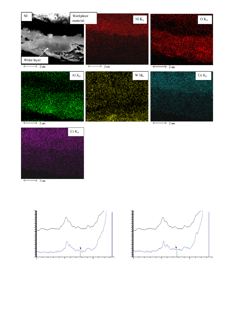
Fig. 6
Elemental map of the white layer on the surface of machined part of ME 16 alloy. Cutting speed 40 m/min
8
7
9
10
11
12
13
14
15
16
17
18
30
40
Core material
Core material
White layer
White layer
γ-alumina phase,
thin surface layer
γ-alumina phase
cannot be
detected by XRD
Diffraction angle, 2
Θ, (degrees)
30
40
Diffraction angle, 2
Θ, (degrees)
(b)
(a)
X-ray intensity,
arb. uints
8
7
9
10
11
12
13
14
15
16
17
18
X-ray intensity,
arb. uints
Fig. 7
XRD spectra of white layer and workpiece material for machined surface of ME 16 alloy. Cutting speed: (a) 50 m/min and
(b) 40 m/min
Journal of Materials Engineering and Performance
Volume 19(7) October 2010—1035
4. Conclusions
Investigations of the tool life and surface integrity of the
machined part made of Ni-based ME 16 alloy show that
machining by a finishing turning operation of ME 16 alloy
results in a 2-4 lm thick white layer formation on the
machined surface, depending on the machining conditions.
This layer contains oxygen with a high amount of aluminum,
enriched by chromium and tungsten. Under specific cutting
conditions, the structure of the white layer transforms into
c-alumina. This ceramic layer is thermally resistant, brittle,
and abrasive. Due to the formation of the thermal barrier
alumina-content white layer, the heat generated during
cutting may not be evenly absorbed by the core of workpiece
material. This could negatively affect surface integrity of the
machined parts and cutting tool life at the higher cutting
speed.
Acknowledgment
This research was funded by Pratt & Whitney Canada.
References
1. Superalloy Optimized for High-Temperature Performance in High-
Pressure Turbine Disks, U.S. Patent 6,521,175, 2 Nov 2003
2. Nickel Based Superalloy Compositions, Articles, and Methods of
Manufacture, EP Patent 1,710,322 A1, 11 Oct 2006
3. J. Gayda and T.P. Gabb, Fatigue Behavior of a Third Generation PM
Disk Superalloy, NASA/TM—2008-215462, Glenn Research Center,
Cleveland, OH, 2008
4. G.D. Smith, Future Trends in Key Nickel Alloy Markets, JOM, 2006,
58(9), p 38
5. R. Arunachalam and M.A. Mannan, Machinability of Nickel-Based
High Temperature Alloys, Mach. Sci. Technol., 2000, 4(1), p 127–168
6. L. Settineri and R. Levi, Surface Properties and Performance of
Multilayer Coated Tools in Turning Inconel, CIRP Ann., 2005, 54(1),
p 515–518
7. D.A. Axinte, P. Andrews, W. Li, N. Gindy, and P.J. Withers, Turning of
Advanced Ni Based Alloys Obtained via Powder Metallurgy Route,
CIRP Ann., 2006, 55(1), p 117–120
8. T.P. Gabb, J. Telesman, P.T. Kantzos, P.J. Bonacuse, R.L. Barrie, and
D.J. Hornbach, Stress Relaxation in Powder Metallurgy Superalloy
Disks, TMS Lett., 2004, 1(5), p 115–116
9. G. Boothroyd and W.A. Knight, Fundamentals of Machining and
Machine Tools, CRC Press, Boca Raton, 2006
10. P.T. Gabb, A. Garg, D.L. Ellis, and M.K. OÕConnor, Detailed
Microstructural Characterization of the Disk Alloy ME3, NASA/TM-
2004-213066, NASA, Washington, DC, 2004
11. P.S. Sklad, C.J. McHargue, C.W. White, and G.C. Farlow, High Tech
Ceramic, P. Vincenzini, Ed., Elsevier, Amsterdam, 1987, p 1073
12. C.W. White, L.A. Boatner, P.S. Sklad, C.J. McHargue, J. Rankin, G.C.
Farlow, and M.J. Aziz, Ion Implantation and Annealing of Crystalline Oxides
and Ceramic Materials, Nucl. Instrum. Methods B, 1988, 32(11), p 115–116
13. G. Poulachon, A. Albert, M. Schluraff, and I.S. Jawahir, An
Experimental Investigation of Work Material Microstructure Effects
on White Layer Formation in PCBN Hard Turning, Int. J. Mach. Tools
Manuf., 2005, 2, p 211–218
14. A. Ramesh, S.N. Melkote, L.F. Allard, L. Riester, and T.R. Watkins,
Analysis of White Layers Formed in Hard Turning of AISI 52100
Steel, Mater. Sci. Eng. A, 2005, 390, p 88–97
15. J. Vinodh Jose and M.S. Shunmugam, Investigation into White Layer
Formed on Wire Electrical Discharge Machined Ti6Al4V Surface, Int.
J. Mach. Mater., 2009, 6(3–4), p 234–249
Fig. 8
Microhardness distribution on the surface of machined part
made of ME 16 alloy. Cutting speed 30-50 m/min
1036—Volume 19(7) October 2010
Journal of Materials Engineering and Performance
Document Outline
Wyszukiwarka
Podobne podstrony:
16 197 208 Material Behaviour of Powder Metall Tool Steels in Tensile
a probalilistic investigation of c f slope stability
Endoscopic investigation of the Nieznany
13 161 172 Investigation of Soldiering Reaction in Magnesium High Pressure Die Casting Dies
8 95 111 Investigation of Friction and Wear Mechanism of Hot Forging Steels
Investigation of Barite Sag in Weighted Drilling Fluids in Highly Deviated Wells
Investigation Of Economic Crimes Attention Of Dr J P Mutonyi
Investigation of bioactive compounds
3 T Proton MRS Investigation of Glutamate and Glutamine in Adolescents at High Genetic Risk for Schi
ABC Investigation of liver correct
a probalilistic investigation of c f slope stability
An investigation of shock induced temperature rise and melting of bismuth using high speed optical p
cathinone an investigation of several N alkyl and methylenedioxy substituted analogs pharmacolbioche
Greene, Joshua D & other An fMRI Investigation of Emotional Engagement in Moral Judgement
Torsion Experimental Investigation of New Long range Actions Nachalov & Sokolov p11
więcej podobnych podstron