1
INTRODUCTION
GENERAL
This section has the description and repair procedures
for the steering housing and the steering control unit.
Additional information on parts of the steering system
are in the following sections: STEERING AXLE and
HYDRAULIC SYSTEM.
DESCRIPTION
This section covers the steering column assembly used
on the “XM” series of lift trucks. This assembly uses a
steering control unit with hose connections on the bot-
tom of the unit. See FIGURE 4. The steering housing
has the mounts for the steering column and the steering
control unit. The steering wheel is installed on the steer-
ing column. The housing is adjustable and is held in
position by a latch. The position of the housing can be
changed for operator comfort. The steering housing is
also the mount for some control levers and the instru-
ment cluster.
The steering system is a hydraulic system that does not
have a mechanical connection between the steering
wheel and the steering axle. The control of the steering
is through a hydraulic circuit.
If the hydraulic pump for the steering system does not
operate, steering is still possible. A check valve permits
the steering control unit to control the steering cylinder.
The lift truck is difficult to steer when the steering pump
is not operating, but the steering control unit can operate
the steering cylinder and make steering possible.
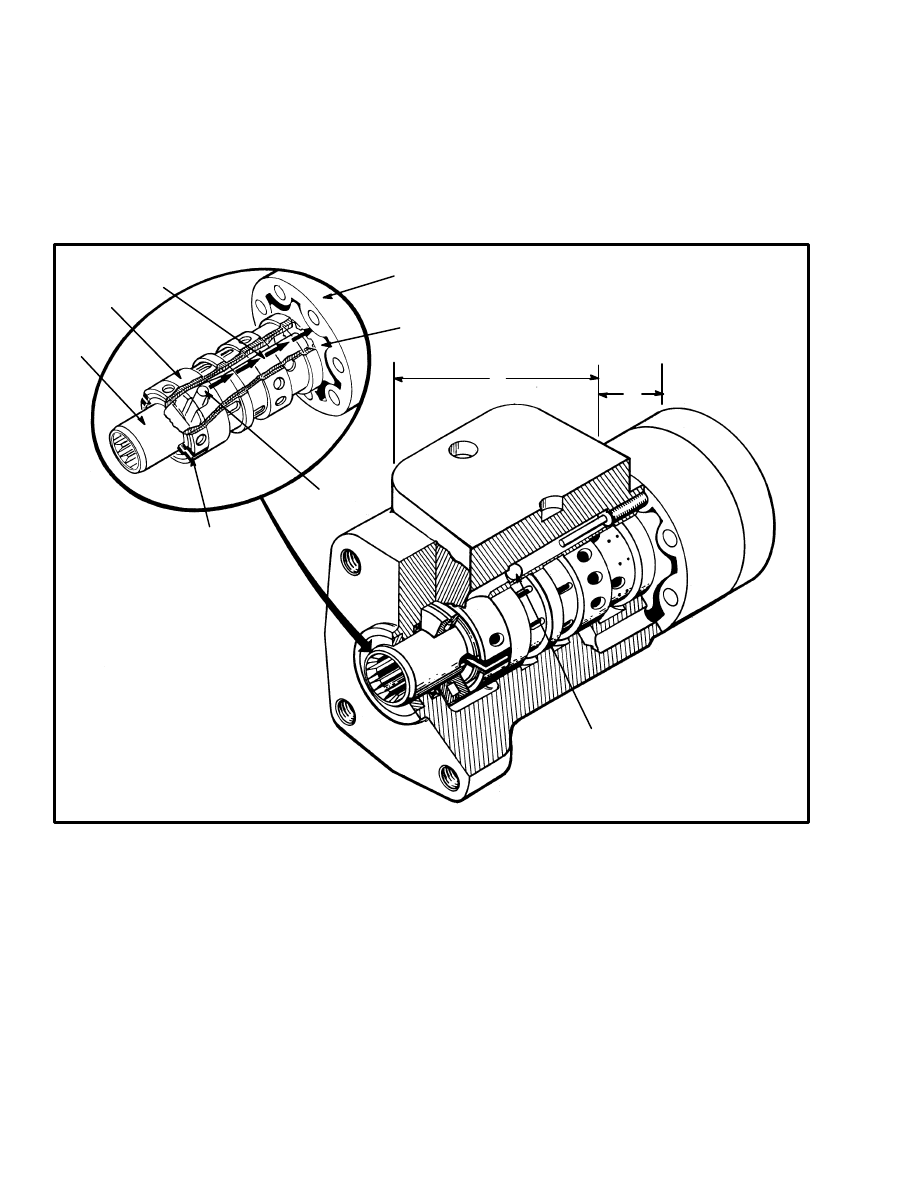
OPERATION (See FIGURE 2.)
The steering control unit is a rotary valve operated by
the steering wheel. During the steering operation, the
steering control unit controls the direction of flow and
amount of oil that flows to the steering cylinder. The
steering cylinder in the axle actuates the steering linkage
to move the steer tires. Hydraulic oil returns from the
steering cylinder to the steering control unit and then re-
turns to the hydraulic tank.
Turning the steering wheel actuates three main parts of
the steering control unit: (1) The spool for the control
section, (2) the sleeve for the control section and (3) the
rotor in the metering section. When the steering wheel is
not moving, the spool and sleeve are held in the neutral
(center) position by springs. During this time, oil flows
freely through the steering control unit. The oil does not
flow to the steering cylinder.
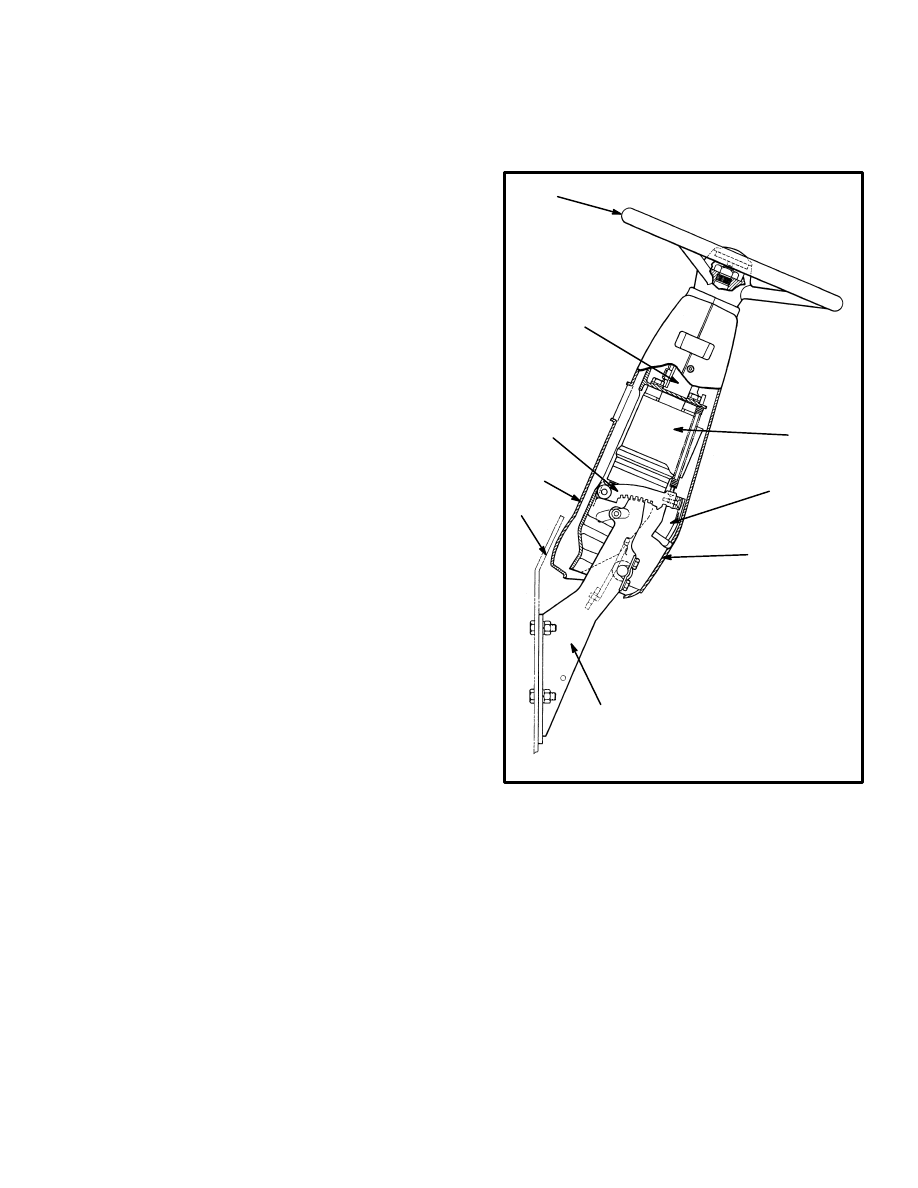
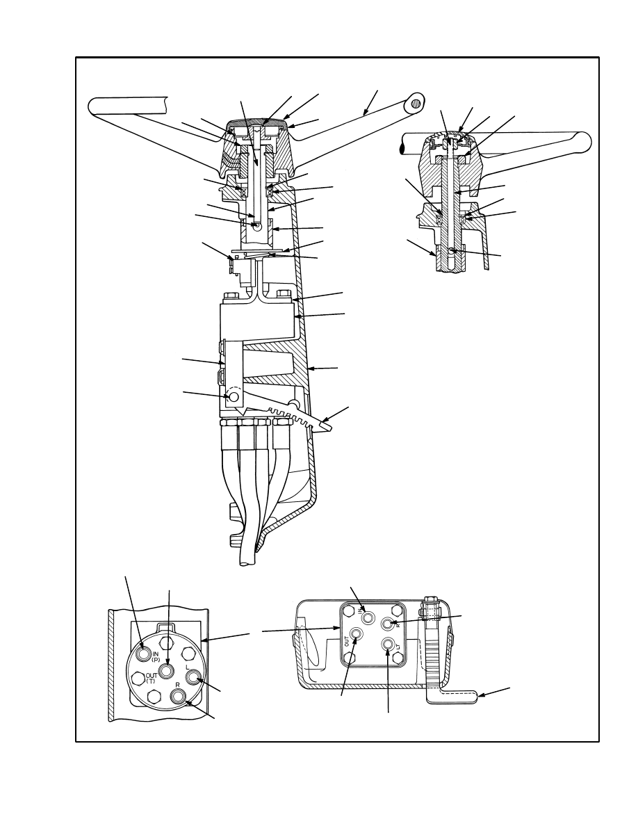
FIGURE 1. STEERING HOUSING ASSEMBLY
1. STEERING WHEEL
2. STEERING COLUMN
3. STEERING
CONTROL UNIT
4. KNOB
5. LATCH
6. COVER
7. COWL
8. MOUNT
1
2
3
4
5
6
7
8
6
H2.00–3.20XM
(H45–65XM)
SHOWN
NOTE: Instrument cluster not shown.
As the steering wheel is turned, the spool just begins to
rotate. The springs try to move the sleeve to keep the
neutral position between the spool and sleeve. However,
the force necessary to turn the rotor is greater than the
pressure of the springs. The springs begin to bend, let-
ting the spool move a small amount within the sleeve.
The spool stops moving when it touches the center pin.
In this position, the holes in the sleeve and the spool are
aligned. Oil coming into the control unit flows to the
metering section.
More rotation of the steering wheel causes the spool to
rotate the pin. This action causes the rotation of the
sleeve and the rotor in the metering section. The oil then
2
flows to one side of the steering cylinder. Hydraulic oil
from the other side of the steering cylinder returns
through the control section of the steering control unit.
When the steering wheel stops moving, the metering ac-
tion in the metering section also stops. The neutral posi-
tion springs return the sleeve to the neutral position
stopping oil flow to or from the cylinder. The pressure
stays in the steering cylinder to keep the steer tires in po-
sition. Oil from the pump flows through the steering
control unit to the tank or other parts of the system. To
return the steer wheels to the straight position, the steer-
ing wheel must be rotated in the opposite direction. The
steering control unit will operate as described, but all
parts will rotate in the opposite direction.
1. SPRING SET
2. SPOOL
3. SLEEVE
4. CENTER SHAFT
5. STATOR
6. ROTOR
7. CONTROL SECTION
8. METERING SECTION
9. CHECK BALL
10. CENTER PIN
FIGURE 2. STEERING CONTROL UNIT
1
2
4
5
6
7
3
8
9
10
REPAIRS
STEERING WHEEL AND COLUMN
ASSEMBLY
(See FIGURE 3. through FIGURE 5.)
The upper end of the steering shaft has splines for the
steering wheel. A large nut holds the steering wheel onto
the steering shaft. The horn button is the cover for the
center of the steering wheel. The lower end of the steer-
ing shaft has splines or a tang to engage the steering con-
trol unit. A push rod from the horn button actuates the
horn switch.
The steering column assembly is adjustable and held in
position by a latch. The position of the steering column
assembly can be changed as needed for different opera-
tor requirements. An access cover on the steering col-
umn give access to the steering control unit, key switch,
horn switch and if installed, the direction switch.
3
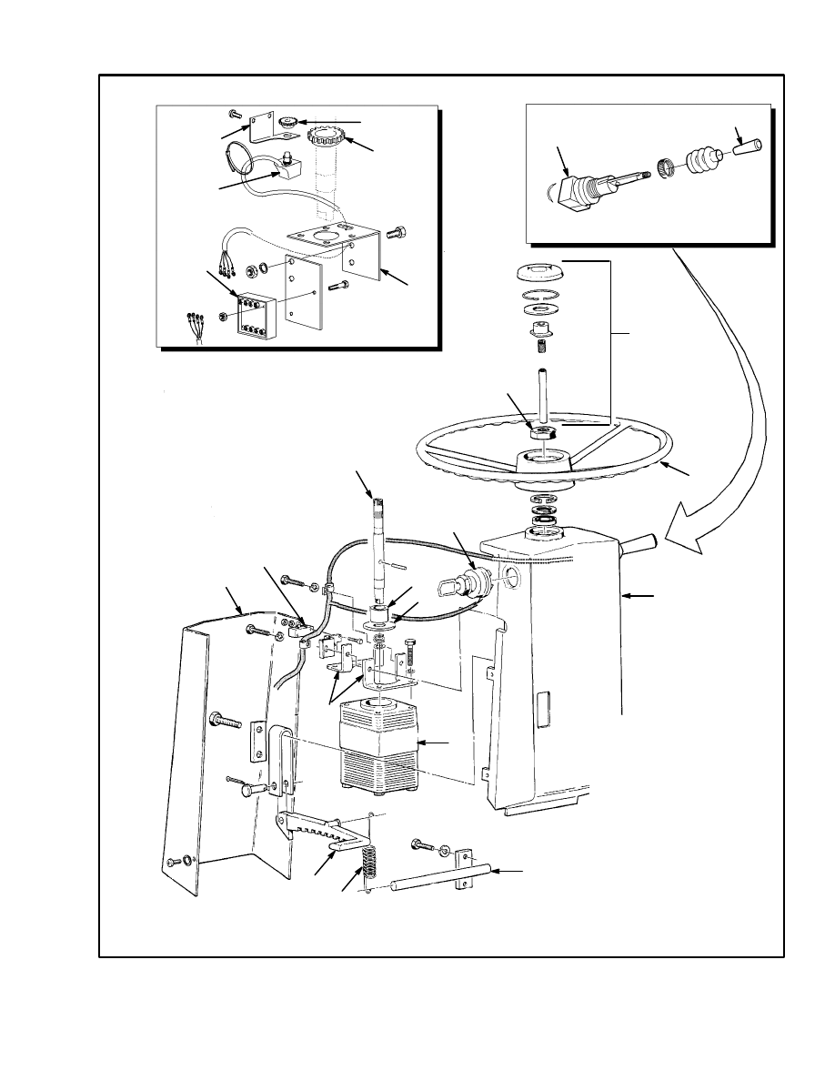
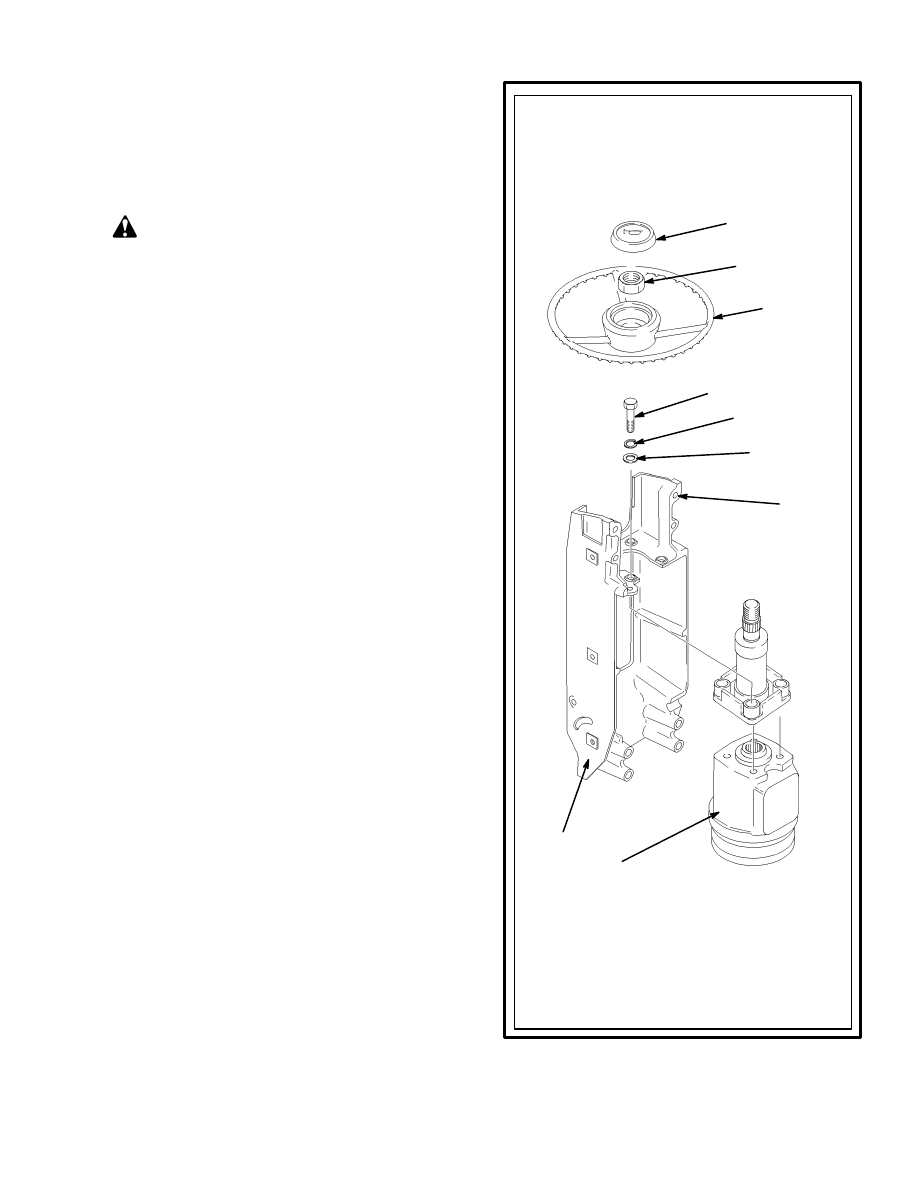
1. HORN BUTTON ASSEMBLY
2. NUT
3. STEERING WHEEL
4. STEERING COLUMN
HOUSING
5. KEY SWITCH
6. STEERING COLUMN
7. SLEEVE
8. WASHER
9. HORN SWITCH
10. REAR COVER
11. CONTROL UNIT
MOUNT BRACKET
12. STEERING CONTROL
UNIT
13. LATCH
14. SPRING
15. PIN
16. DRIVEN GEAR
17. DRIVE GEAR
18. BRACKET
19. OPTICAL ENCODER
20. TRANSDUCER
21. DIRECTION SWITCH
22. DIRECTION LEVER
HANDLE
FIGURE 3. STEERING WHEEL AND STEERING COLUMN ASSEMBLY
On–Demand Power Steering (Optional)
4
22
2
5
7
8
12
11
9
3
13
10
14
15
21
18
19
16
17
18
20
TYPICAL ARRANGEMENT ELECTRIC
UNITS
Direction Lever (Optional)
1
6
4
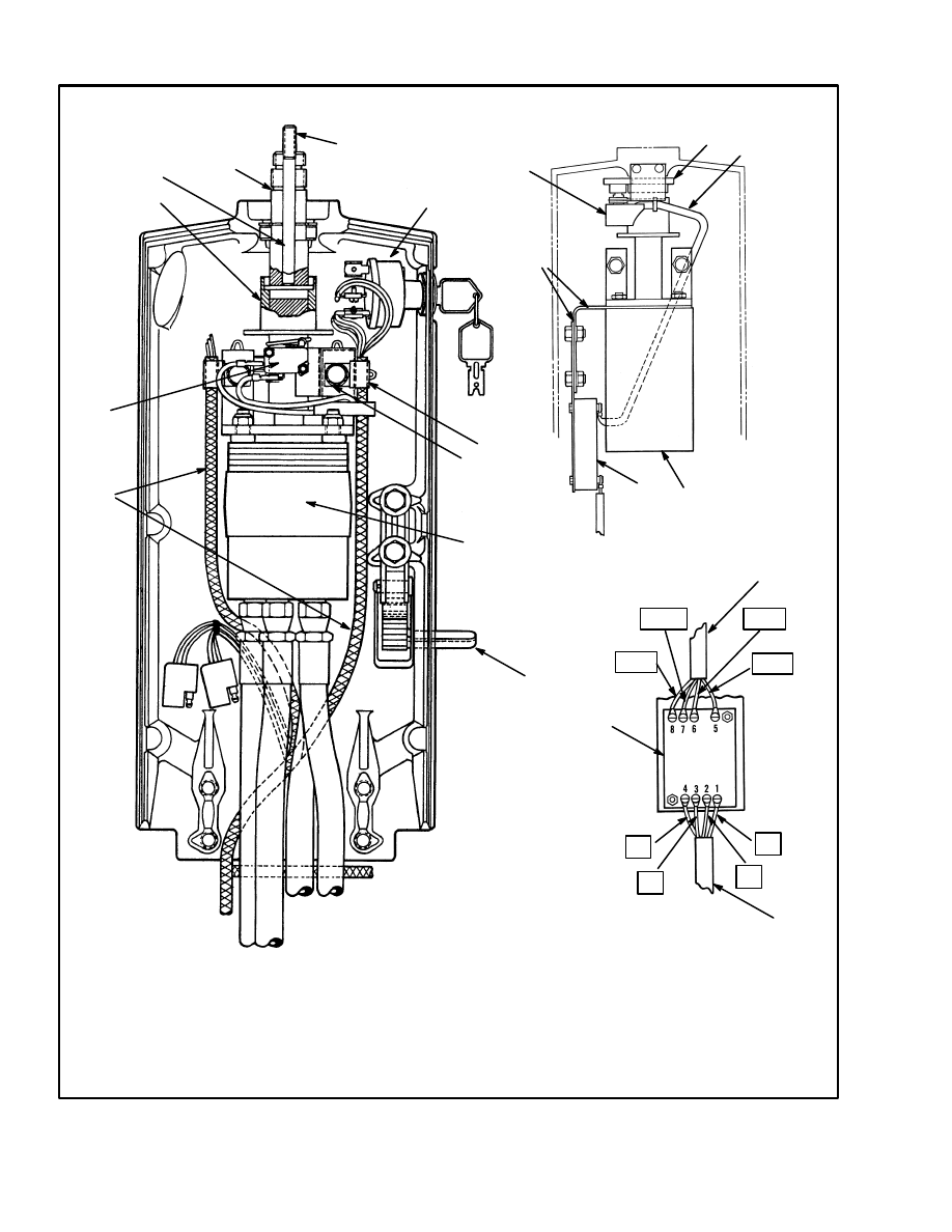
FIGURE 4. STEERING COLUMN ASSEMBLY
GRN
RED
BLK
WHT
13
63
61
10
1
1. STEERING CONTROL UNIT
2. STEERING SHAFT
3. PLASTIC TUBE
4. LATCH
5. PIN
11. SOCKET HEAD SCREW
12. ACTIVATOR ASSEMBLY
13. BRACKET
14. OPTICAL ENCODER AND
BRACKET
15. ENCODER/ACTIVATOR WIRE
HARNESS
1
2
3
4
5
6
7
8
9
10
11
12
13
14
15
10
12
14
15
11959
6. KEY SWITCH
7. CLAMP
8. BRACKET
9. HORN SWITCH
10. LIFT TRUCK WIRE HARNESS
REAR VIEW
5
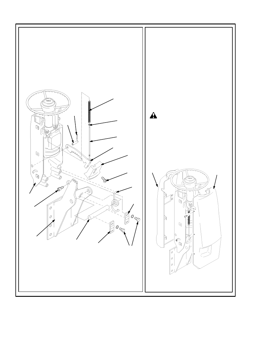
FIGURE 5. STEERING WHEEL AND STEERING COLUMN ASSEMBLY
11959
1. STEERING COLUMN
2. STEERING CONTROL UNIT
3. BRACKET
4. STEERING WHEEL
5. STEERING SHAFT
6. HORN COVER
7. BASE PLATE
8. BEARING
9. PLASTIC TUBE
10. PLASTIC WASHER
11. SPRING
12. LATCH
13. LOCK RING
14. ADJUSTER SPOOL NUT
15. STEERING WHEEL NUT
16. EXTERNAL SNAP RING
17. INTERNAL SNAP RING
18. PUSH ROD
19. PIN
20. HORN SWITCH
21. BRACKET
22. LATCH PIVOT PIN
23. SOCKET HEAD SCREW
PETRI STEERING WHEEL
19
9
8
16
17
18
15
14
6
18
4
7
6
14
18
13
15
16
20
19
18
11
10
9
5
8
3
17
2
1
12
22
23
21
TRW
DANFOSS
INPUT
RETURN
RIGHT TURN
LEFT TURN
INPUT
RETURN
RIGHT TURN
LEFT TURN
2
12
SIDE VIEW

6
Removal Of The Assembly Components
(See FIGURE 3., FIGURE 4. and FIGURE 5.)
NOTE: This procedure is for the removal of all compo-
nents of the steering column assembly. All components
are not often removed for a repair procedure. Do only
those steps of the procedure necessary to remove the re-
quired component.
CAUTION
Disconnect the negative battery cable on internal
combustion trucks. Disconnect the battery connec-
tor on electric trucks. Disconnect the battery before
removing any covers.
1. Attach a tag on the battery connector or negative cable
stating “DO NOT CONNECT BATTERY”. Move the
steering column to the most forward position. Remove
the access cover from the steering column.
2. Remove the key switch from the housing of the steer-
ing column. Make an identification of the electric wires
and disconnect them from the key switch.
3. On units with the Direction Control Handle, remove
the handle, dust cover and large nut that fastens the di-
rection switch. Remove the direction switch from the
housing of the steering column. Make an identification
of the electric wires and disconnect them from the direc-
tion switch.
4. Remove the capscrew that fastens the bracket for the
horn switch to the housing of the steering column. Move
the horn switch and bracket away from the steering col-
umn.
5. Remove the horn cover, snap ring and base plate (no
base plate in Petri steering wheel, see FIGURE 5.). Lift
the push rod and adjuster spool from the top of the steer-
ing shaft. Remove the large hex nut and remove the
steering wheel from the shaft. A puller makes removal
of the steering wheel easier, but not all steering wheels
have puller holes.
6. Some electric units have On–Demand steering. Re-
move the optical encoder and activator and the brackets
of the On–Demand steering. Make an identification of
the electrical wires and disconnect them from the as-
semblies.
7. Make an identification of the hydraulic hoses at the
steering control unit so they can be connected correctly
during assembly. Some hydraulic hoses have fittings
that will permit disconnection at the steering control
unit. Disconnect the other hydraulic hoses at the base of
the cowl, the control valve or the steering pump. Re-
move all mount clamps so that the hoses will turn freely
and not become twisted. Disconnect the hydraulic hoses
at the bottom of the steering control unit. Install plugs at
all hoses and ports to prevent dirt from entering the
steering hydraulic system.
8. If there is a display panel on the steering column hous-
ing, disconnect all plugs connected to the display panel.
NOTE: The repair procedures for the instrument cluster
for the S/H2.00–3.20XM (S/H40–65XM) and
H/S1.50–2.00XMS (H/S30–40XMS) are in the section
INSTRUMENT CLUSTER, 2200 SRM 514.
NOTE: The repair procedures for the instrument cluster
for the E/J2.00–3.20XM (E/J45–65XM),
J1.60–2.00XMT (J30–40XMT) and N30XMH are in
the section ELECTRICAL SYSTEM, 2200 SRM
560.
9. Remove the capscrews, lock washers and lock plates
that fasten the steering column to the pivots on the lift
truck. Remove the steering column from the lift truck.
Make sure the electric wires and the hydraulic hoses are
not damaged as the steering column is removed.
10. Do the following procedure to remove the steering
shaft:
a. Move the plastic tube and washer toward the
steering control unit and compress the spring for
the horn switch. Then remove the pin that goes
through the steering shaft and engages the plastic
tube.
b. Remove the external snap ring that holds the
bearing in the steering column. On units that have
On–Demand steering, loosen the set screw in the
gear on the shaft. The return spring, washer and
tube are removed at the same time as the steering
shaft and bearing are removed. Use a small pry-
bar at the bottom of the steering shaft near the
steering control unit to remove the steering shaft
and bearing (also, return spring, washer and tube)
from the steering column.
11. Remove the two capscrews that hold the steering
control unit and the bracket to the steering column. Re-
move the four capscrews or nuts that fasten the steering
control unit to the bracket.
7
Disassembly Of The Steering Control Unit
Disassemble the steering control unit as shown in
FIGURE 7.
Cleaning Of The Steering Control Unit
WARNING
Cleaning solvents can be flammable and toxic, and
can cause skin irritation. When using cleaning sol-
vents, always follow the solvent manufacturer’s rec-
ommended safety precautions.
Clean all the parts in solvent. Dry the parts with com-
pressed air. Do not dry the parts with a cloth. Make sure
all surfaces are free of scratches and sharp edges.
Assembly Of The Steering Control Unit
Use new seals, O–rings and neutral position springs dur-
ing assembly as shown in FIGURE 8. Lubricate all parts
with clean hydraulic oil.
Installation Of The Steering Control Unit
Install the steering control unit and column assembly on
the bracket as shown in FIGURE 6.
Installation Of The Assembly Components
1. Install the steering column on the cowl mounts. Lu-
bricate the pivots with multi–purpose grease and install
the capscrews into the housing.
2. Fasten the two halves of the mount bracket to the
steering control unit. Make sure to install bracket for the
activator assembly. Install the steering control unit as-
sembly into the steering column. Make sure to install the
horn switch and the switch bracket as well as the two
wire clamps on the same mount capscrews.
3. If removed, install the wires on the key switch that
were identified during removal. Install the key switch.
4. If removed, install the wires on the direction switch
that were identified during removal. The correct con-
nections are also shown in FIGURE 4. Install the direc-
tion switch in the housing and install the large nut, dust
cover and handle.
FIGURE 6. ASSEMBLY OF THE “XM”
STEERING HOUSING (1 of 2)
1. HORN BUTTON
2. NUT
3. STEERING
WHEEL
4. CAPSCREW
5. LOCK WASHER
6. WASHER
STEP 1.
Install the steering column and steering control
unit in the bracket. Install the steering wheel
and nut. Tighten the nut to 40 to 54 Nm (30 to
40 lb
f
ft). Connect the wire at the horn button
and install the horn button.
1
2
3
7. STEERING
COLUMN
8. BRACKET
9. STEERING
CONTROL
UNIT
4
6
5
7
9
8
8
STEP 2.
Install the mount on the cowl. Install the latch on the bracket,
using the pin and cotter pin. Install the bracket on the mount
with the pivot shaft and spring. Install the plates and cap-
screws that hold the bracket to the shaft. Install the spring,
washer and rod for the latch. Install the knob on the latch.
Install the allen screw and nut.
11
10
12
13
14
15
1
2
3
4
1. MOUNT
2. PIVOT SHAFT
3. PLATE
4. CAPSCREW
5. SPRING
6. SCREW
7. KNOB
8. LATCH
9. ROD
10. WASHER
11. SPRING
12. COTTER PIN
13. PIN
14. BRACKET
15. ALLEN SCREW
9
8
7
6
3
5
STEP 3.
Install the instrument cluster on the front
cover. See the section INSTRUMENT
CLUSTER, 2200 SRM 514 to make the
necessary wiring connections for the
S/H2.00–3.200XM (S/H40–65XM).
See the section ELECTRICAL SYSTEM,
2200 SRM 560 to make the necessary
wiring connections for the
J2.00–3.20XM (J40–65XM),
E2.00–3.20XM (E45–65XM),
J1.60–2.00XMT (J30–40XMT) and
N30XMH. Install the covers on the brack-
et. Connect the hydraulic lines to the
steering control unit.
The hydraulic hoses MUST be con-
nected to the correct ports or the
steering system will not operate as
expected. This operation that is not
expected can cause damage or per-
sonal injury. Make sure the hoses are
identified and connected correctly.
1. FRONT COVER
2. REAR COVER
1
2
FIGURE 6. ASSEMBLY OF THE “XM” STEERING HOUSING (2 of 2)
WARNING
9
5. Install the bearing on the steering shaft. The seal of the
bearing must be toward the steering wheel. Install the
snap ring in the groove on the steering shaft.
6. Put the steering shaft through the opening for the
bearing in the steering housing. Install the pin that holds
the plastic tube and flange for the horn switch. Install
the plastic tube, the plastic flange and the spring onto the
steering shaft. Push the steering shaft into the splines or
align the key way of the steering control unit. Install the
snap ring that holds the bearing in the steering housing.
7. Install the steering wheel. Install the large hex nut
onto the steering shaft. Install the push rod and adjuster
spool into the steering shaft. Install the base plate (not
part of Petri steering wheel), the lock ring and the horn
cover.
WARNING
The hydraulic hoses MUST be connected to the cor-
rect ports and fittings or the steering system will not
operate as expected. This operation that is not ex-
pected can cause damage or personal injury. Make
sure the hoses are identified and connected correctly.
8. Connect the hydraulic hoses to the steering control
unit, the cowl, the control valve or the steering pump as
removed during removal. Make sure each hydraulic
hose is connected to the correct ports or fittings as iden-
tified during removal.
9. Connect the wire connectors at the bottom of the
steering column. Install the access cover on the steering
column.
WARNING
After making repairs, do not extend the hands or
arms through the center of the steering wheel. If the
control unit was not assembled correctly or the hoses
not connected correctly it can rotate with a strong
force and cause serious injury. If this action occurs,
disassemble the control unit and correct the prob-
lem.
10. Connect the battery and operate the steering system
to check for correct operation and leaks.
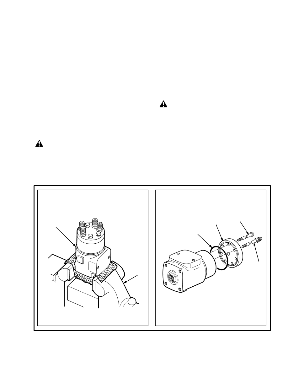
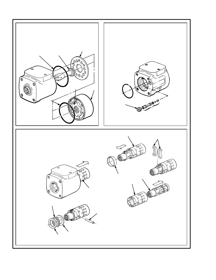
STEP 2.
Remove the cover on the bottom of the steering
control unit. Remove the check ball.
1. STEERING CONTROL UNIT
2. VISE
11877
11876
FIGURE 7. DISASSEMBLY OF THE STEERING CONTROL UNIT (1 of 3)
1. CAPSCREW
2. COVER
3. O–RING
4. SPECIAL
FITTING
STEP 1.
Put the control unit in a vise with soft jaws. Make
an identification mark on the length of the control
unit.
1
2
1
2
3
4
10
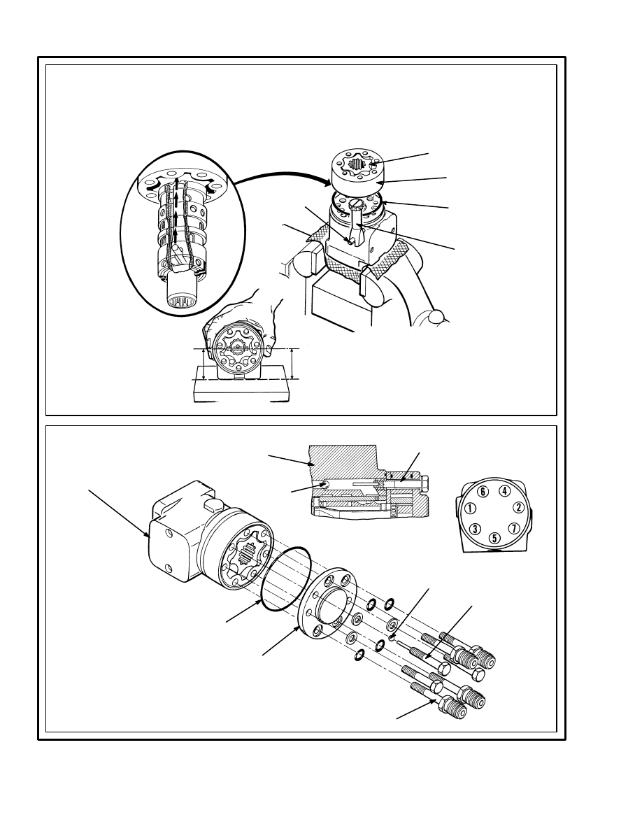
STEP 5.
Remove the spool and sleeve assembly. Remove the
thrust bearing assembly from the spool. Push the cen-
ter pin from the sleeve. Carefully remove the spool from
the sleeve. Rotate the spool slowly during removal. Re-
move the ring from the sleeve. Remove the neutral po-
sition springs from the spool. Remove the seal from the
housing.
STEP 3.
Remove the stator, rotor and port plate. Put a
mark on the stator so that the same side will be
toward the body of the control unit at assembly.
Remove the O–rings. Remove the center shaft.
1. STATOR
2. ROTOR
3. PORT PLATE
4. O–RING
5. CENTER SHAFT
1
2
4
5
3
4
STEP 4.
Remove the screw for the check valve assembly.
Remove the parts for the check valve. For some
units the check ball is in the opposite end of the
control unit.
11875
1. SCREW
2. CHECK VALVE ASSEMBLY
1
2
FIGURE 7. DISASSEMBLY OF THE STEERING CONTROL UNIT (2 of 3)
11877
1. SPOOL AND SLEEVE ASSEMBLY
2. THRUST WASHER
3. THRUST BEARING
4. CENTER PIN
5. SLEEVE
6. SPOOL
7. RING
8. NEUTRAL POSITION SPRINGS
1
2
3
2
4
7
8
5
6
5
11
FIGURE 7. DISASSEMBLY OF THE STEERING CONTROL UNIT (3 of 3)
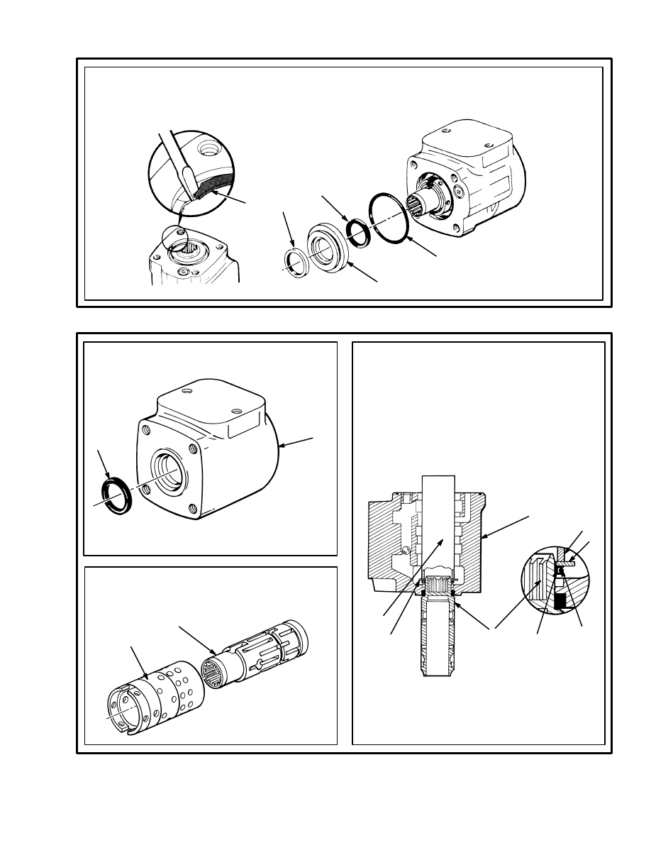
STEP 6.
When installed, remove the snap ring, bushing,
O–ring and seal ring. Remove the oil seal from
the bushing or housing.
1. SNAP RING
2. SEAL
3. BUSHING
4. O–RING
5. OIL SEAL
11876
1
2
3
4
5
STEP 1.
Install the seal.
1. HOUSING
2. SEAL
1
2
STEP 2.
Put the spool (3) on the work bench then put the
housing (6) onto the spool as shown. Install the
guide ring (2) with the O–ring (1) on the end of
the spool. Put the thrust washer (4), (see STEP
6) on top of the guide ring and O–ring assembly.
Use a socket or tube (5) to push on the washer
and install the O–ring and guide ring in the hous-
ing. Carefully remove the washer, tube and spool
from the housing.
4. WASHER
5. TUBE
6. HOUSING
1
2
3
4
5
6
4
STEP 3.
Carefully assemble the spool and sleeve. Make
sure the spool rotates freely in the sleeve.
1. SPOOL
2. SLEEVE
2
1
1. O–RING
2. GUIDE RING
3. SPOOL
FIGURE 8. ASSEMBLY OF THE STEERING CONTROL UNIT (1 of 4)
5
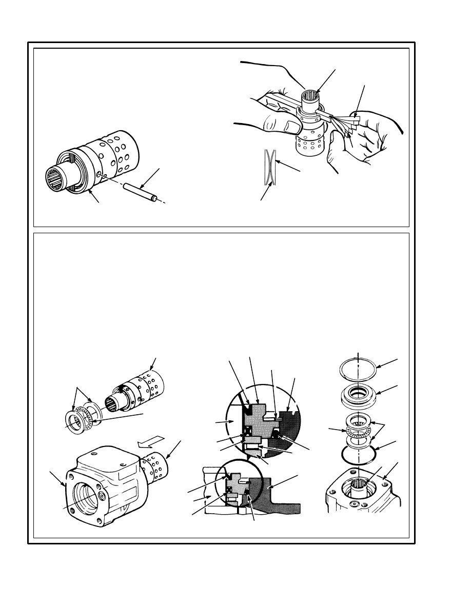
12
2
3. CENTER PIN
4. SPOOL
5. RING
1. NEUTRAL POSITION
SPRINGS (FLAT)
2. NEUTRAL POSITION
SPRINGS (CURVED)
STEP 4.
Assemble the neutral position springs then push
them into position in the spool (4). Make sure the
flat springs (1) are installed to the outside of the
curved springs (2). Install the center pin (3). Install
the ring (5) on the sleeve (over the neutral position
springs). The ring must turn freely on the sleeve.
1
4
1
3
5
FIGURE 8. ASSEMBLY OF THE STEERING CONTROL UNIT (2 of 4)
2
STEP 5.
When the control unit has the type of bearing
arrangement shown here, use the following pro-
cedures:
Install the thrust washers and thrust bearing on
the spool. Carefully install the spool and sleeve
assembly in the housing. Install the dust seal (9)
in the bushing (6). Install the bushing (6), seal
(8) and the O–ring (3) in the housing. Use the
snap ring (7) to hold the bushing in position.
Make sure the sleeve rotates freely in the hous-
ing.
1. HOUSING
2. SPOOL AND SLEEVE ASSEMBLY
3. O–RING
4. THRUST WASHER
5. THRUST BEARING
6. BUSHING
7. SNAP RING
8. SEAL
9. DUST SEAL
11879
1
2
4
7
9
9
1
1
1
2
2
2
2
3
3
3
4
4
4
5
5
7
6
8
8
5
6
13
STEP 6.
Install the thrust washers (3) and thrust bearing
(4) on the spool (5). Make sure the chamfer on
the inner thrust washer is next to the sleeve (6).
Install the spool and sleeve assembly in the
housing. Carefully rotate the spool and sleeve
assembly during installation to make sure the
spool fits correctly in the seal installed in STEP 1.
Make sure the center pin (7) in the spool and
sleeve assembly is horizontal.
4. THRUST
BEARING
5. SPOOL
6. SLEEVE
7. PIN
1. HOUSING
2. O–RING
3. PORT PLATE
1. HOUSING
2. SPOOL AND
SLEEVE ASSEMBLY
3. THRUST WASHER
4
3
5
1
2
7
6
2
3
1
FIGURE 8. ASSEMBLY OF THE STEERING CONTROL UNIT (3 of 4)
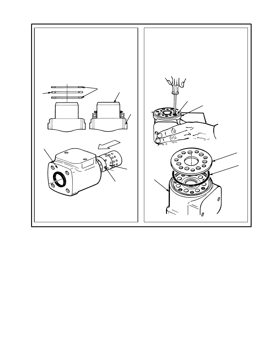
STEP 7.
When the check valve is at the end of the housing
as shown here, install the check ball and sleeve.
Make sure the sleeve is even with or below the
surface of the housing (1). Lubricate the O–ring (2)
and install the O–ring and port plate (3). Align the
holes in the port plate with the holes in the hous-
ing.
11885
1
2
14
STEP 8.
Install the center shaft (1) so that it engages with the center pin (2) in spool and sleeve assembly. Make
sure the center pin is still parallel to the flat surface of the housing. Install the rotor (3) on the center shaft.
Make sure that a valley in the rotor aligns with the slot (center pin) in the center shaft. Install the O–ring (5)
and stator (4). Make sure to align the marks made during disassembly.
1. CENTER SHAFT
2. CENTER PIN
3. ROTOR
4. STATOR
5. O–RING
STEP 9.
Install the O–ring (2) and the cover (3). If removed during disas-
sembly, install the spacer (not shown). Tighten the capscrews
for the cover in the sequence shown to 17 Nm (150 lbf in), then
tighten them to 30 Nm (265 lbf in). Make sure the capscrew (4)
with the pin fits in the hole for the check ball (5).
1. HOUSING
2. O–RING
3. COVER
4. CAPSCREW
5. CHECK BALL
6. SPECIAL FITTING
FIGURE 8. ASSEMBLY OF THE STEERING CONTROL UNIT (4 of 4)
1
2
3
4
5
6
3
2
1
5
4
4
5
1
15
CHECKS AND ADJUSTMENTS
REMOVE AIR FROM THE SYSTEM
Air can enter the system when a hydraulic line is discon-
nected. If the operation is rough, operate the system and
rotate the steering wheel from stop to stop several times
in each direction. The air will be removed without dis-
connecting any lines. If the operation is still rough,
check if air is entering the system at a loose fitting.
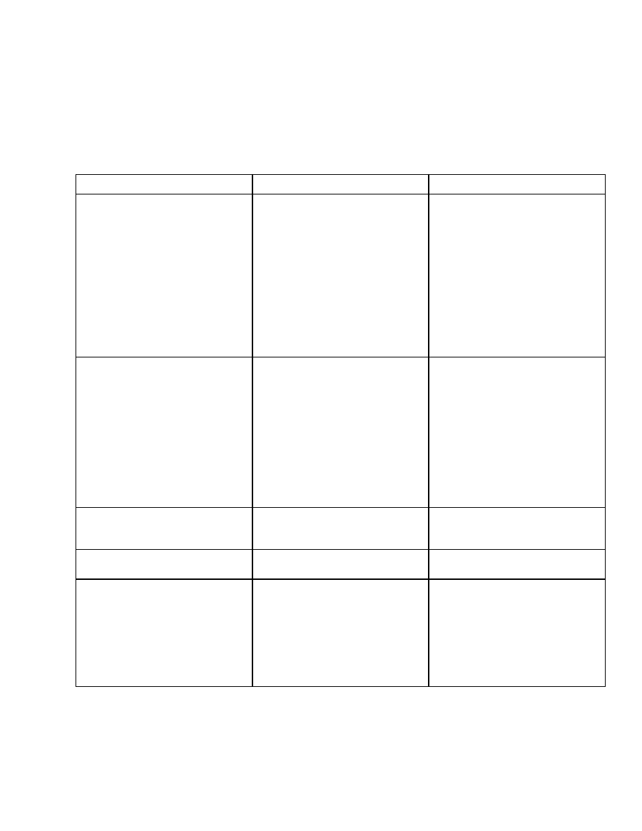
TROUBLESHOOTING
TROUBLE
POSSIBLE CAUSE
PROCEDURE OR ACTION
The steering wheels do not move
when the steering wheel is turned.
The oil level is low or there is no oil
in the tank.
The steering control unit is dam-
aged.
No oil flow from the steering control
unit to the steering cylinder.
The sleeve and spool in the control
unit will not move.
Hydraulic hoses not connected or
have damage.
Fill tank to the correct level. Check
for leaks.
Repair or install new control unit.
Repair or install new components.
Check for leaks.
Install new components.
Check for leaks. Tighten connec-
tions. Install new components as
necessary.
Slow or difficult steering.
Relief valve for the steering system
is not adjusted correctly.
Low oil pressure from the hydraulic
pump.
Seal in the steering cylinder has a
leak.
Hydraulic lines are too small or
have restrictions.
Steering control unit is worn, not as-
sembled correctly or has damage.
Adjust or install new relief valve.
Check for restrictions. See Trouble-
shooting Chart, ”Hydraulic System”.
Repair cylinder. Install new seal or
new cylinder.
Remove restrictions. Install larger or
new hydraulic lines.
Repair or install new control unit.
Steering wheel turns the tires in the
wrong direction.
The hydraulic lines are not con-
nected correctly at the steering cyl-
inder or at the steering control unit.
Connect lines correctly. Remove air
from the system.
Steering function continues after the
steering wheel stops.
The steering control unit is as-
sembled wrong or has damage.
Repair or install new control unit.
The steering operation is not
smooth.
The oil level in the tank is low.
Air was not removed after repair to
the hydraulic system.
The steering control unit is as-
sembled wrong or has damage.
The hydraulic pump has a leak at
the inlet.
Fill tank. Check for leaks.
Remove air from the system.
Repair or install new control unit.
Fix leaks. Remove air from the sys-
tem.
16
Document Outline
Wyszukiwarka
Podobne podstrony:
897493 1600SRM0512 (11 1995) UK EN
897497 2000SRM0516 (11 1995) UK EN
897820 2200SRM0595 (11 1995) UK EN
1470230 1600SRM0786 (11 2003) UK EN
897493 1600SRM0512 (08 2003) US EN
1459370 1600SRM0720 (07 2005) UK EN
1452929 2200SRM0679 (11 2003) UK EN
897953 1600SRM0639 (03 2005) UK EN
1466205 2100SRM0735 (11 2004) UK EN
897986 1600SRM0658 (03 1997) UK EN
1466241 1600SRM0732 (10 2003) UK EN
1554636 8000SRM1080 (11 2004) UK EN
910460 1600SRM0258 (05 2004) UK EN
1565582 1600SRM1114 (04 2005) UK EN
1453608 1600SRM0687 (03 2002) UK EN
1466193 2200SRM0755 (11 2001) UK EN
więcej podobnych podstron