
0
50
100
150
200°C
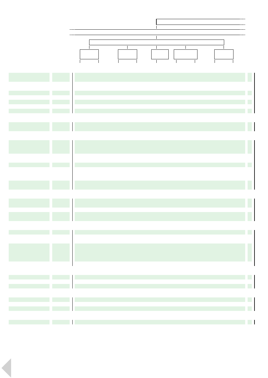
15000 MPa
12500
10000
7500
5000
2500
0
Lexan
•
nt
HB
V2
V0
5VB
5V
A
0
40
80
120
160
200 MPa
100 kJ/m
2
80
60
40
20
0
Modulus
profile
Lexan
®
release
09//1998
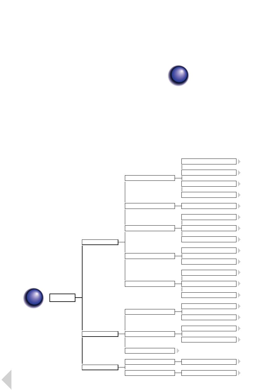
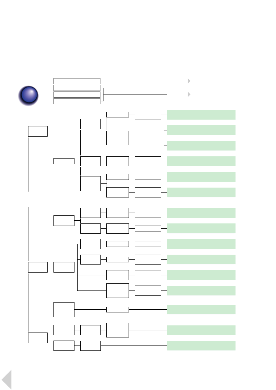
C o n t e n t s
. . . . . . . . . . . . . . . . . . . .
. . . . . . . . . . . . . . . . . . . . . . . .
P r o d u c t S e l e c t i o n
P r o p e r t i e s a n d D e s i g n
General properties . . . . . . . . . . . . . . . . . . . . . . . . 26
Mechanical properties . . . . . . . . . . . . . . . . . . . . . 26
Thermal properties . . . . . . . . . . . . . . . . . . . . . . . . 33
Flammability . . . . . . . . . . . . . . . . . . . . . . . . . . . . 33
Electrical properties . . . . . . . . . . . . . . . . . . . . . . 35
Aesthetics and optical properties . . . . . . . . . . . . 36
Environmental resistance . . . . . . . . . . . . . . . . . . . 37
Processibility . . . . . . . . . . . . . . . . . . . . . . . . . . . . 41
Mould shrinkage . . . . . . . . . . . . . . . . . . . . . . . . . 43
. . . . . . . . . . . . . . . . . . . . . 44
Pre-drying . . . . . . . . . . . . . . . . . . . . . . . . . . . . . . 44
Equipment . . . . . . . . . . . . . . . . . . . . . . . . . . . . . . 44
Processing conditions . . . . . . . . . . . . . . . . . . . . . 44
Venting . . . . . . . . . . . . . . . . . . . . . . . . . . . . . . . . . 44
Interruption of production . . . . . . . . . . . . . . . . . . 45
Purging of the barrel . . . . . . . . . . . . . . . . . . . . . . 45
Recycling . . . . . . . . . . . . . . . . . . . . . . . . . . . . . . . 45
S e c o n d a r y O p e r a t i o n s
Welding . . . . . . . . . . . . . . . . . . . . . . . . . . . . . . . . 46
Adhesives . . . . . . . . . . . . . . . . . . . . . . . . . . . . . . 44
Mechanical assembly . . . . . . . . . . . . . . . . . . . . . . 46
Painting . . . . . . . . . . . . . . . . . . . . . . . . . . . . . . . . 47
Metallisation . . . . . . . . . . . . . . . . . . . . . . . . . . . . 47
Laser marking . . . . . . . . . . . . . . . . . . . . . . . . . . . 48
L e x a n P r o f i l e
2
C o n t e n t s
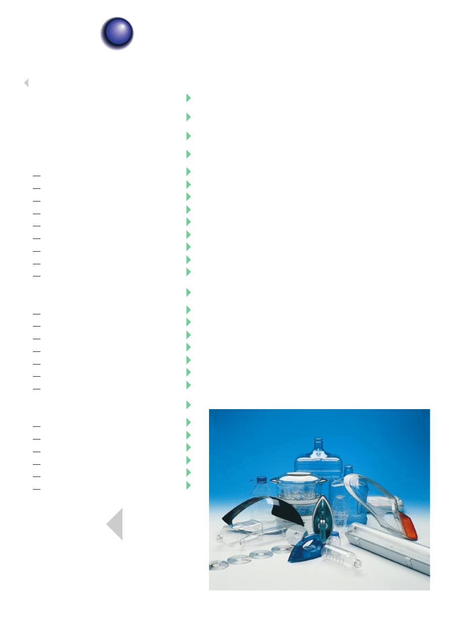
Lexan polycarbonate is an
amorphous engineering
thermoplastic which is characterized
by high levels of mechanical, optical,
electrical and thermal properties.
The Lexan portfolio provides broad
design versatility through its wide
range of viscosities and product
options. These options include
halogen-free flame retardancy, impact
modification, glass-reinforcement,
optical quality and compliance with
stringent FDA and USP requirements.
The key properties which are
inherent in Lexan resin include:
·
High impact resistance over a wide
range of temperatures
·
Glass clear transparency
·
Wide range of colours
·
High gloss, quality surface finish
·
Excellent optical clarity
·
Excellent heat resistance: almost all
grades pass 125°C ball pressure test
·
Inherent limited flame retardancy:
all grades pass 850°C glow wire test
at 1.0 mm
Lexan resins are tailor-made for a
range of conversion processes
including injection moulding,
extrusion, blow moulding and foam
processing. High flow grades have
been developed which are ideally
suited to thin wall, long flow length
applications.
After their first application life, Lexan
resins can be reground and reused.
As is characteristic of an engineering
thermoplastic, Lexan resins retain a
high residual value and, in many
cases, they can be recycled into
similar applications within the same
industry. Alternatively, they can be
cascaded down for reuse in less
demanding applications.
1
1
I n t r o d u c t i o n
Lexan
®
Polycarbonate Resins
PC
Electrical
With its broad portfolio of flame
retarded and non-flame retarded
grades, both unreinforced and glass
reinforced, Lexan resin is found in
a wide range of electrical products.
These include meter and fuse box
housings, domestic switches, plugs
and sockets, switchgear, relays and
connectors.
Lexan resin’s key properties for the
electrotechnical industry include its:
·
Halogen-free* flame retarded system,
with most grades passing the Glow
Wire Test at 850°C
·
Excellent thermal properties with all
grades passing the Ball Pressure Test
at 125°C
·
Quality surface finish, high gloss or
textured, in a wide range of colours
·
High impact resistance
·
Good resistance to tracking and
arcing (CTI >175 volts)
·
Constant electrical properties in
aggressive environments
·
Excellent processibility
·
Compatibility with lasermarking
process
In addition, Lexan 3412R offers a
V0 flammability rating at wall
thicknesses of 0.8 mm according
to UL94 to meet the most critical
performance requirements of thin
walled connectors. Lexan 900 series
is specified for applications where
extremely low smoke evolution is a
requirement.
*
in accordance with
DIN VDE472 part 815
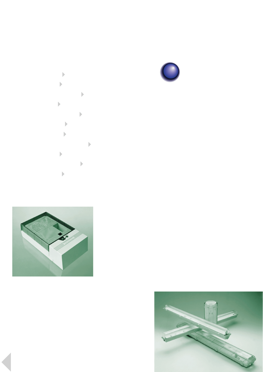
Lighting
Lexan resin is well-established in
the lighting industry, providing
manufacturers with lightweight,
quality parts, fast cycle times through
consistent processibility and
unlimited opportunities for design
integration and intricate, snap-fit
assembly.
Typical applications include linear
fluorescent luminaires, street lamps,
traffic lights, spotlights, reflectors,
lamp holders, emergency lights,
explosion-proof lights, conduits,
electrical supply track systems and
diffusers where Lexan resin features:
·
Outstanding impact resistance over
a wide range of temperatures, from
sub-zero to +125°C
·
Excellent optical properties
·
High heat resistance, with an HDT
under load of 133°C
·
Excellent dimensional stability and
low uniform shrinkage
·
Good resistance to tracking and
arcing (CTI >175 volts)
·
Good UV stability
·
Inherent corrosion resistance and
long-term weatherability; scratch and
chemical resistance can be further
increased through the application of
a GE Silicones’ hardcoat
·
Wide range of transparent and
opaque colours
2
2
M a r k e t s

Telecommunications
Lexan resin is the material of choice
for a range of indoor and outdoor
telecommunications enclosures,
including power supply connection
boxes and base-stations, where it
features:
·
High temperature resistance
·
Good impact strength
·
Good dimensional stability
·
Good UV stability
·
Halogen-free* flame retarded
·
Quality aesthetics
Lexan structural foam grades are
an ideal choice for structural
components where load-bearing
capability at elevated temperatures
is a key requirement. They are an
excellent alternative to metal or
other plastics for the efficient
production of large parts such
as outdoor distribution cabinets.
Here they provide important weight
savings through an inherently high
stiffness to weight ratio. Furthermore,
for optimum UV protection, parts
can be easily painted.
*
in accordance with
DIN VDE472 part 815
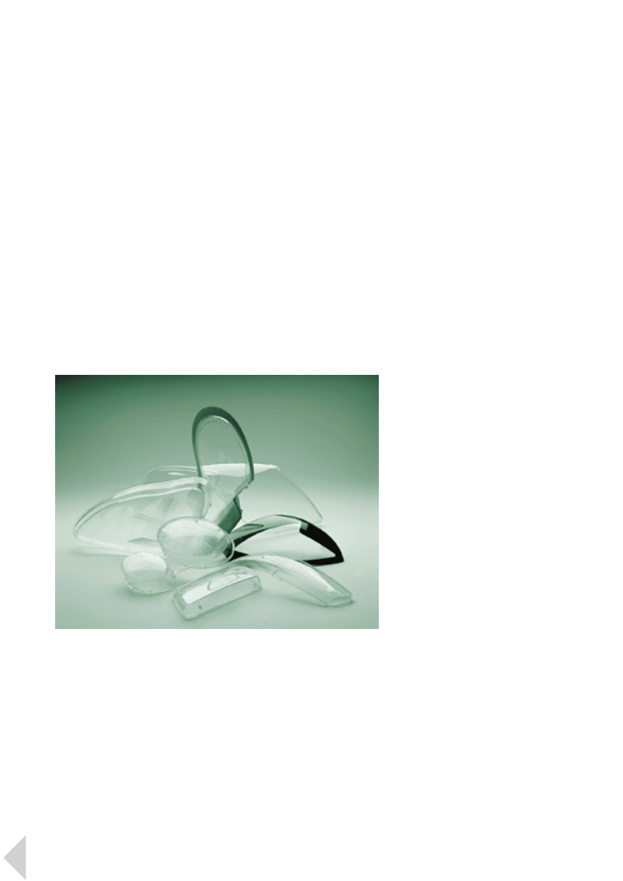
Optical
The family of Lexan optical quality
(OQ) resins has been specifically
developed for the optical industry.
The range includes high impact
grades for safety goggles, optical
quality clean-room grades for
corrective lenses and grades offering
maximum UV screening up to
400 nm for sunglasses and ski visors.
Lexan OQ resins pass internationally
recognized industry standards
offering a tailor-made property
portfolio which includes:
·
‘Water white’ clarity, achieved
through proprietary technology
·
Light transmission >88%
·
Built-in UV screen
·
High impact resistance across
temperatures ranging from
sub-zero to +125°C
·
High temperature resistance allowing
the application of various anti-scratch
coatings
·
Excellent dimensional stability and
low water absorption
·
High refractive index of 1.586 which
allows the production of lenses which
are up to 20% thinner than with
traditional materials
·
Low specific gravity compared to
traditional materials, producing
lighter lenses
·
Fast, cost-efficient injection moulding
cycles and a high degree of precision
·
Unlimited design freedom to create
two-and three-dimensional shapes
3
L e x a n P r o f i l e 2 M a r k e t s
4
L e x a n P r o f i l e 2 M a r k e t s
Automotive lighting
Tough, lightweight Lexan LS resins
have been specifically developed for
headlamp lenses. Their unlimited
design flexibility and moulding
precision allows them to be formed
into complex shapes. Accurate
refraction planes provide exceptional
lighting performance, while
integrated fixings reduce
components and simplify assembly.
GE Silicones’ proprietary hardcoating
system provides optimum abrasion
resistance throughout the life of
the vehicle. As well as providing
manufacturers with consistent high
quality, Lexan resin can considerably
enhance productivity when the lens
is designed as part of a total lighting
system.
Lexan resin is also ideally suited to
the production of bezels which can
be metallized without the use of a
primer or lacquer. Manufacturers can
produce lightweight, state-of-the-art
parts with optimum cost-efficiency
thanks to Lexan resin’s inherent
design freedom and opportunities
for thin wall moulding and part
integration.
Appliances
Lexan resin is widely used in the
appliances industry for products such
as food mixers and processors, steam
iron water tanks and oven control
panels where its key features are its:
·
Exceptional practical impact
resistance
·
High heat resistance
·
Consistent processibility
·
High quality glass-like transparency
and gloss
·
Wide range of colours, with many
colours having transparent and
translucent as well as opaque versions
·
Inherent design freedom
For products like vacuum cleaner
motor end-caps, diffusers and brush
holders which require superior
rigidity and stiffness, glass-filled
Lexan polycarbonate offers high
modulus and high impact
performance, combined with ease
of assembly through unlimited
opportunities for design integration
and intricate, snap-fit assembly.
Following market trends for cost
reduction and product
differentiation, GE Plastics has
recently developed in partnership
with industry two innovative
appliance concepts which
demonstrate the unique advantages
of using Lexan polycarbonate. The
first is an oven door which features:
·
Cool-to-the-touch properties which
are due to the thermal conductivity
of Lexan resin being down to four
times less than that of glass
·
Cost-efficient product differentiation
through in-mould finishing which
involves placing a pre-printed,
vacuum formed Lexan film in the
door mould prior to injection
moulding
·
Inherent design freedom for cost-
efficient styling advantages to achieve,
for example, fashionable, rounded
shapes
·
Enhanced productivity through snap-
fit assembly
The second design concept is an
injection moulded, circular dryer
door. This single component
comprises an integrated locking
mechanism, frame, bull’s-eye window
and hinge. Cost-effective variations in
colour and decoration can be easily
achieved through in-mould finishing.
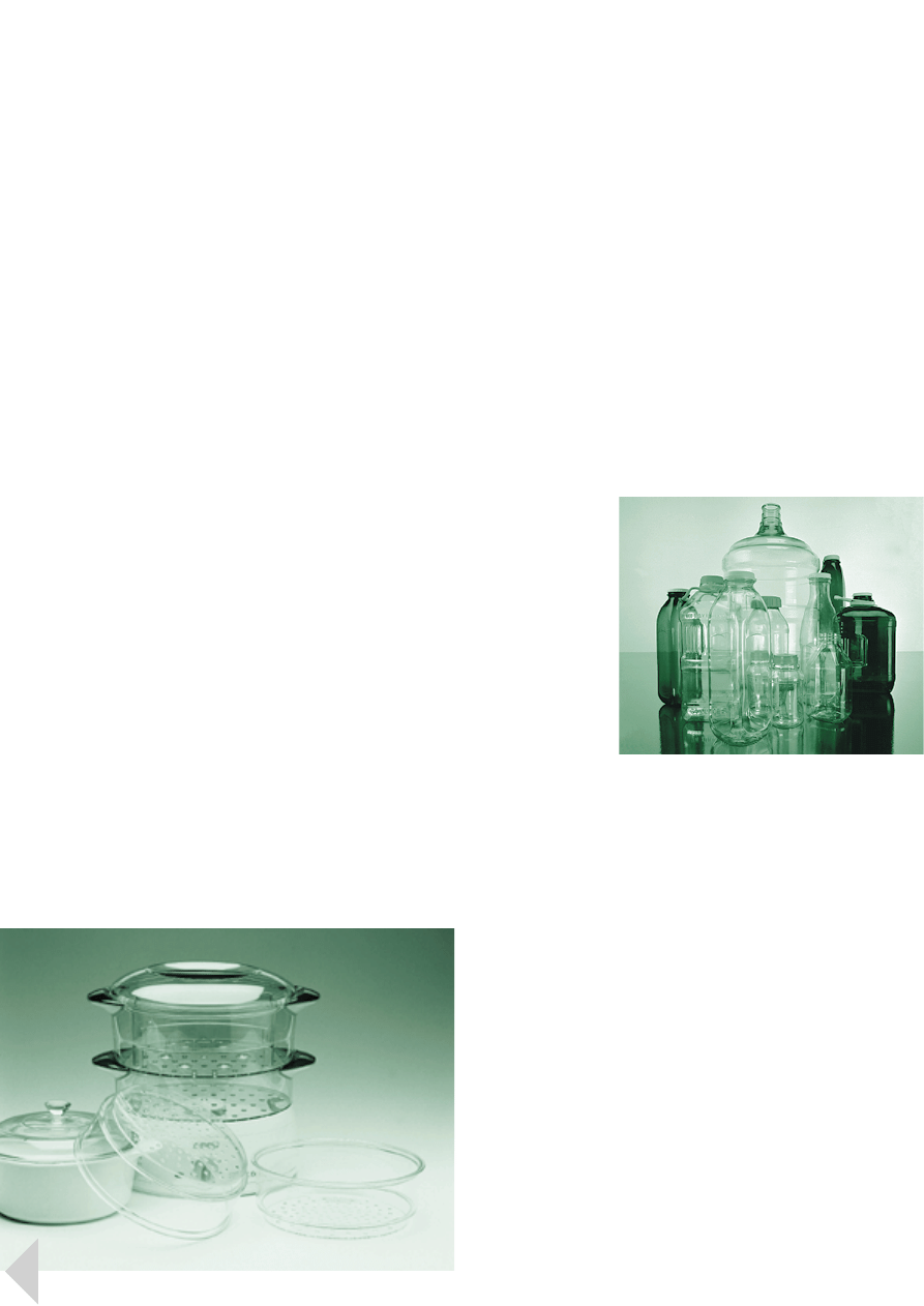
Packaging
The use of Lexan polycarbonate
returnable milk bottles is well-
established as a cost-effective, user-
and environment-friendly alternative
to glass and to one-way disposable
cartons and plastic bottles. Popular
with dairy, distributor and consumer
alike, the Lexan resin bottle can be
washed and refilled up to 50 times
while maintaining excellent taste
neutrality and its characteristic high
quality, glass-like transparency.
The key advantages of Lexan resin
in milk packaging are its:
·
Glass-like transparency and gloss
·
Excellent taste and aroma protection
in compliance with FDA and
European food contact regulations
·
High impact properties and practical
toughness for safe handling
·
High temperature resistance to
withstand repeated wash cycles
·
Light weight for ease of handling and
cost-effective transportation
·
Compatibility with existing materials
handling systems
·
Wide design flexibility for a diversity
of bottle shapes, sizes and features
·
Wide range of colours
·
Recyclability for use in other non-
food applications
Lexan resin is also used in the
production of water bottles where,
as with milk packaging, its key
properties are its taste neutrality,
high temperature resistance for
cleanability and its long life
expectancy compared with glass
products. Tailor-made branched
resin, Lexan PKG1643, offers
moulders the ability to produce
a high quality water bottle with a
more uniform wall thickness.
In food packaging applications,
Lexan resin can also be used as a top
layer in the coextrusion of multi-layer
film where it provides:
·
High mechanical strength
·
High heat resistance
·
High gloss
·
Good slip, anti-blocking and film
winding properties
5
L e x a n P r o f i l e 2 M a r k e t s
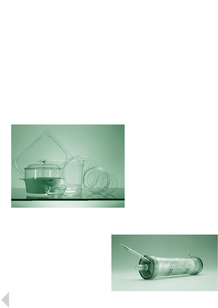
Table- and kitchen-ware
Lexan polycarbonate table- and
kitchen-ware is well-established in
the domestic, commercial and
institutional catering markets.
In addition to full compliance with
FDA and European food legislation,
Lexan resin offers these markets the
following key benefits:
·
Inherent high impact strength and
practical toughness for products
which are virtually unbreakable
·
Excellent thermal and dimensional
stability allowing repeated washing at
high temperatures and reheating of
foodstuffs using hot air, water bath
or microwave oven
Medical
Lexan polycarbonate meets the
requirements of the FDA and USP
Chapter XXII Class V1 for use in the
medical industry. It is widely used for
a variety of medical devices and
equipment including trocar tubes,
syringes, dialysis apparatus, blood
filters and blood oxygenators.
Products can be sterilized by all three
commonly used methods: gamma
radiation, EtO gas and steam
(autoclave). Superior colour stability
and resistance to yellowing following
gamma or EtO sterilisation is a key
feature of tailor-made Lexan GR
grades.
The key properties of Lexan resin
in medical applications are its:
·
High impact resistance
·
High temperature resistance
·
Glass-like clarity
·
Good processibility
·
Design versatility
6
L e x a n P r o f i l e 2 M a r k e t s
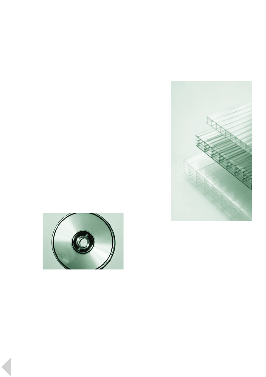
Optical disc storage
With dedicated manufacturing
facilities in the Netherlands, USA
and Japan, GE Plastics is the only
global supplier of polycarbonate
resins to optical disc market. Tailor-
made Lexan Optical Quality (OQ)
resins are renowned for their
excellent product consistency, both
in terms of purity and processibility.
Due to their low molecular weight,
these materials have an ultra-high
melt flow rate which allows the
moulding of discs with very low
birefringence and excellent pit and
track replication.
Working closely with its industry
partners, GE Plastics continues to
push forward with state-of-the-art
materials and process technology
which will revolutionize the
production of new optical media.
Included in recent developments is
a further improved flow Lexan OQ
resin which features lower
birefringence, enhanced surface
replication and superior flatness
for the DVD format.
Extrusion
Specially developed UV-stable Lexan
extrusion resins can be readily
extruded on conventional
equipment. The range includes both
linear and branched polymers for
solid, multi- and twin-wall sheet
extrusion.
In general, Lexan extrusion grades
offer:
·
Consistent ease of processing
·
Excellent surface finish and
transparency
·
Outstanding impact performance
In addition, glass clear UV cap-layer
materials have been specifically
developed to improve the UV
performance of extruded solid, multi-
and twin-wall polycarbonate sheet.
For typical applications such as
roofing sheets, these unique materials
meet critical industry standards for
outdoor weatherability, while
providing enhanced productivity.
7
L e x a n P r o f i l e 2 M a r k e t s
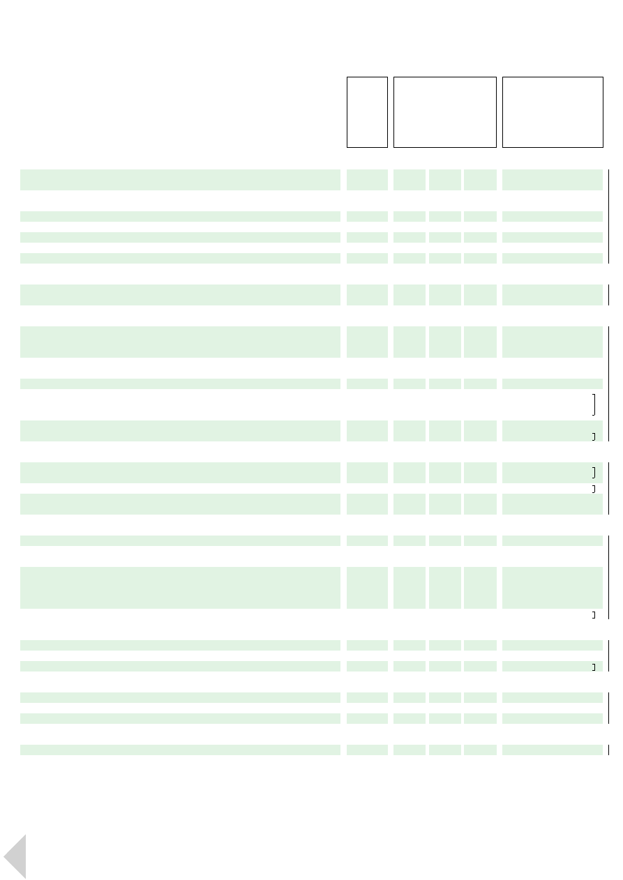
Lexan 100 Series
(Unreinforced, Non-Flame Retarded)
·
Wide viscosity range:
120 series: low viscosity
140 series: low to medium viscosity
160 series: medium viscosity
100 series: high viscosity
130 series: very high viscosity
·
R grades have easy release
characteristics
·
1x3R grades are UV stabilized
·
1x4R grades comply with various
food contact regulations
·
All grades have wide colour
availability
Lexan HF Series (High Flow)
·
Formulated using a unique
chemical modification of the base
polycarbonate polymer
·
Very low viscosity levels with minimal
reduction in inherent properties
·
Ideally suited to thin wall, high flow
length applications
·
All grades have easy release
characteristics
·
HF1130R is UV stabilized
·
HF1140R is suitable for food and
medical applications
8
see page 11
see page 9
see page 13
see page 15
flame retarded UL94V2 2xy series
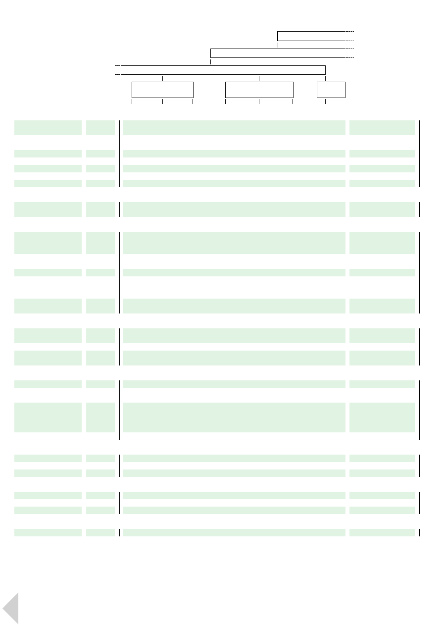
3
P r o d u c t S e l e c t i o n
9
L e x a n P r o f i l e 3 P r o d u c t S e l e c t i o n
flame retarded UL94V2 2xy series
FLOW
144R
142°C
•
25 (10) kJ/m
2
•
2300 MPa
HB/1.14 mm
•
12 cm
3
/10min
124R
141°C
•
12 (10) kJ/m
2
•
2300 MPa
HB/1.14 mm
•
21 cm
3
/10min
123R
141°C
•
12 (10) kJ/m
2
•
2300 MPa
HB/1.47 mm
•
21 cm
3
/10min
ML3729
140°C
•
12 (4) kJ/m
2
•
2300 MPa
V2/0.80 mm
•
40 cm
3
/10min
HF1110R
140°C
•
12 (10) kJ/m
2
•
2300 MPa
V2/1.09 mm
•
26 cm
3
/10min
HF1130R
140°C
•
12 (10) kJ/m
2
•
2300 MPa
V2/1.60 mm
•
26 cm
3
/10min
HF1140R
140°C
•
12 (10) kJ/m
2
•
2300 MPa
V2/1.09 mm
•
26 cm
3
/10min
121 / 121R
141°C
•
12 (10) kJ/m
2
•
2300 MPa
HB/1.14 mm
•
21 cm
3
/10min
143 / 143R
142°C
•
25 (10) kJ/m
2
•
2300 MPa
HB/1.47 mm
•
12 cm
3
/10min
164R
145°C
•
60 (10) kJ/m
2
•
2300 MPa
HB/1.14 mm
•
9 cm
3
/10min
104R
145°C
•
65 (10) kJ/m
2
•
2300 MPa
HB/1.14 mm
•
6 cm
3
/10min
134R
145°C
•
65 (10) kJ/m
2
•
2300 MPa
V2/1.60 mm
•
3 cm
3
/10min
141 / 141R
142°C
•
25 (10) kJ/m
2
•
2300 MPa
HB/1.14 mm
•
12 cm
3
/10min
163R
145°C
•
60 (10) kJ/m
2
•
2300 MPa
HB/1.47 mm
•
9 cm
3
/10min
161R
145°C
•
60 (10) kJ/m
2
•
2300 MPa
HB/1.14 mm
•
9 cm
3
/10min
103/ 103R
145°C
•
65 (10) kJ/m
2
•
2300 MPa
HB/1.47 mm
•
6 cm
3
/10min
101 / 101R
145°C
•
65 (10) kJ/m
2
•
2300 MPa
HB/1.14 mm
•
6 cm
3
/10min
food, medical & toys
UV stability
food, medical & toys
UV stability
food, medical & toys
UV stability
food, medical & toys
food, medical & toys
food, medical & toys
UV stability
UV stability
UV stability

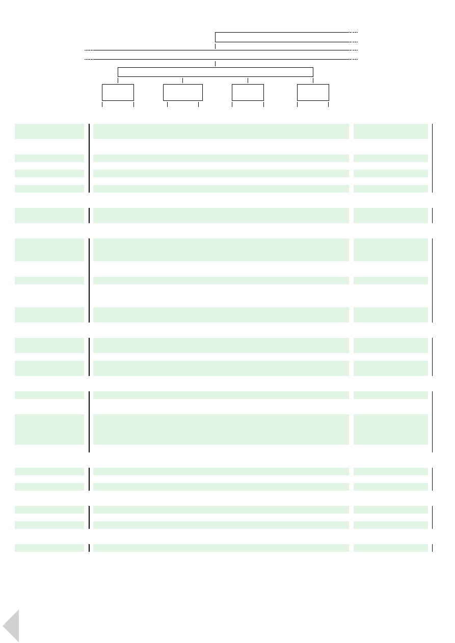
Lexan 200 Series
(Unreinforced, Flame Retarded)
·
Differing levels of viscosity:
220 series: low viscosity
240 series: low to medium viscosity
260 series: medium viscosity
200 series: high viscosity
·
R grades have easy release
characteristics
·
2x3R grades are UV stabilized
·
All grades have wide colour
availability
·
All grades are rated UL94 V2
at measured thickness
Lexan 900 Series
(Unreinforced, Flame Retarded)
·
Transparent and opaque UL94 flame
class rated grades
·
Available in different melt viscosities
·
All products have easy release
characteristics
·
9x3 and 9x3A grades are UV
stabilized
·
9xy series are available only in opaque
colours
·
9xyA series are available in opaque
and transparent colours
10
L e x a n P r o f i l e 3 P r o d u c t S e l e c t i o n
Grade:
‘R’ grades show ‘easy release’
Heat:
Vicat B/120 in °C (ISO 306)
Impact:
Izod Notched at 23 (-30)°C
in kJ/m
2
(ISO 180/1A)
Modulus:
Flexural in MPa (ISO 178)
Flammability:
Flame class at mm thickness
(UL94)
Flow:
MVR at 300°C/1.2kg
in cm
3
/10min (ISO1133)
Flow*:
MVR at 250°C/1.2kg
in cm
3
/10min (ISO1133)
n.t.: not tested · NB: not broken
‘all colours’ means ‘available in transparent,
translucent and opaque colours, unless
otherwise indicated’
GRADE
Heat
•
Impact
•
Modulus
Flammability
•
Flow
11
L e x a n P r o f i l e 3 P r o d u c t S e l e c t i o n
FLOW
FLOW
FLOW
223R
141°C
•
12 (10) kJ/m
2
•
2300 MPa
V2/1.47 mm
•
21 cm
3
/10min
243R
142°C
•
25 (10) kJ/m
2
•
2300 MPa
V2/1.47 mm
•
12 cm
3
/10min
263R
145°C
•
60 (10) kJ/m
2
•
2300 MPa
V2/1.47 mm
•
9 cm
3
/10min
203R
145°C
•
65 (10) kJ/m
2
•
2300 MPa
V2/1.47 mm
•
6 cm
3
/10min
920
141°C
•
9 (7) kJ/m
2
•
2300 MPa
V0/1.04 mm
•
21 cm
3
/10min
923
141°C
•
9 (7) kJ/m
2
•
2300 MPa
V0/1.00 mm
•
21 cm
3
/10min
940
142°C
•
12 (11) kJ/m
2
•
2300 MPa
V0/1.04 mm
•
9.5 cm
3
/10min
943
142°C
•
12 (11) kJ/m
2
•
2300 MPa
V0/1.00 mm
•
9.5 cm
3
/10min
950
145°C
•
15 (n.t.) kJ/m
2
•
2300 MPa
V0/1.04 mm
•
6.5 cm
3
/10min
920A
142°C
•
10 (nt) kJ/m
2
•
2300 MPa
V0/3.05 mm
•
12 cm
3
/10min
923A
142°C
•
10 (nt) kJ/m
2
•
2300 MPa
V0/3.20 mm
•
12 cm
3
/10min
940A
142°C
•
12 (10) kJ/m
2
•
2300 MPa
V0/3.05 mm
•
9.5 cm
3
/10min
943A
142°C
•
12 (10) kJ/m
2
•
2300 MPa
V0/3.20 mm
•
9.5 cm
3
/10min
2014R
145°C
•
8 (8) kJ/m
2
•
2300 MPa
V2/1.47 mm
•
8.5 cm
3
/10min
2034
145°C
•
8 (8) kJ/m
2
•
2300 MPa
V2/1.50 - V0/2.50 mm
•
8.5 cm
3
/10min
221R
141°C
•
12 (10) kJ/m
2
•
2300 MPa
V2/1.14 mm
•
21 cm
3
/10min
241R
142°C
•
25 (10) kJ/m
2
•
2300 MPa
V2/1.14 mm
•
12 cm
3
/10min
261R
145°C
•
60 (10) kJ/m
2
•
2300 MPa
V2/1.14 mm
•
9 cm
3
/10min
201R
145°C
•
65 (10) kJ/m
2
•
2300 MPa
V2/1.14 mm
•
6 cm
3
/10min
UV stability
UV stability
UV stability
UV stability
UV stability
UV stability
UV stability
UV stability
UV stability
easy release

Lexan LS Series (Lens System)
·
Specifically developed for parts
requiring high optical quality,
i.e. clarity and light transmission
·
Range of viscosity levels
·
Lexan LS2 meets all global
automotive OEM specifications in
the US, Europe and Asia, including
SAE 576, the global standard for
outdoor weathering
·
All grades have easy release
characteristics
Lexan Optical Series
·
Tailor-made Lexan OQ (Optical
Quality) resins satisfy stringent purity
requirements of optical data storage
discs
·
Grade with ultra-high melt flow rate
and lower birefringence for high
density DVD market
·
Grades for LCD’s available with
different melt viscosities
·
Special grades for ophthalmic and
safety lenses with superior properties
to acrylic and glass
·
Range of transparent colours
complemented by opaque white for
a very high degree of reflectivity
Lexan Glass Reinforced, Flame
Retarded Series
·
UL94 flame class rated grades
·
Range of multi purpose, standard
length glass fibre reinforced grades,
complemented by a short glass fibre
grade with superior dimensional
stability
·
10% to 40% glass reinforced grades
·
Excellent rigidity, high heat resistance
and superior impact strength
compared with other filled resins
·
Highly stable mechanical and
electrical properties
·
Lower coefficient of thermal
expansion and reduced mould
shrinkage
·
Availability in different viscosity levels
·
R grades have easy release
characteristics
12
L e x a n P r o f i l e 3 P r o d u c t S e l e c t i o n
Grade:
‘R’ grades show ‘easy release’
Heat:
Vicat B/120 in °C (ISO 306)
Impact:
Izod Notched at 23 (-30)°C
in kJ/m
2
(ISO 180/1A)
Modulus:
Flexural in MPa (ISO 178)
Flammability:
Flame class at mm thickness
(UL94)
Flow:
MVR at 300°C/1.2kg
in cm
3
/10min (ISO1133)
Flow*:
MVR at 250°C/1.2kg
in cm
3
/10min (ISO1133)
n.t.: not tested · NB: not broken
‘all colours’ means ‘available in transparent,
translucent and opaque colours, unless
otherwise indicated’
GRADE
Heat
•
Impact
•
Modulus
Flammability
•
Flow
13
L e x a n P r o f i l e 3 P r o d u c t S e l e c t i o n
FLOW
LS1
141°C
•
12 (10) kJ/m
2
•
2300 MPa
HB/1.47 mm
•
21 cm
3
/10min
LS2
142°C
•
25 (11) kJ/m
2
•
2300 MPa
HB/1.47 mm
•
12 cm
3
/10min
LS3
145°C
•
60 (10) kJ/m
2
•
2300 MPa
HB/1.47 mm
•
6 cm
3
/10min
OQ1020LN
142°C
•
10 (4) kJ/m
2
•
2300 MPa
n.t.
•
11*cm
3
/10min
OQ4320
142°C
•
65 (11) kJ/m
2
•
2300 MPa
n.t.
•
12 cm
3
/10min
ML3042
145°C
•
50 (15) kJ/m
2
•
2500 MPa
n.t.
•
6 cm
3
/10min
500R
143°C
•
8 (8) kJ/m
2
•
3400 MPa
V0/1.47 - 5VA/3.05 mm
•
8 cm
3
/10min
503R
143°C
•
8 (8) kJ/m
2
•
3400 MPa
V0/1.47 - 5VA/3.05 mm
•
8 cm
3
/10min
ML3019
142°C
•
n.t. (n.t.)
•
3400 MPa
V0/1.60 mm
•
8 cm
3
/10min
2814R
143°C
•
6 (6) kJ/m
2
•
3400 MPa
V0/1.47 mm
•
6 cm
3
/10min
ML3260
143°C
•
8 (8) kJ/m
2
•
4000 MPa
V1/1.60 mm
•
11 cm
3
/10min
1278R
143°C
•
8 (8) kJ/m
2
•
5000 MPa
V1/1.57 mm
•
12 cm
3
/10min
3412R
145°C
•
8 (6) kJ/m
2
•
5500 MPa
V0/0.80 mm
•
6 cm
3
/10min
3413R
145°C
•
8 (6) kJ/m
2
•
7000 MPa
V0/1.47 mm
•
5 cm
3
/10min
3414R
145°C
•
8 (6) kJ/m
2
•
8500 MPa
V0/1.50 mm
•
4 cm
3
/10min
ML3513
150°C
•
8 (8) kJ/m
2
•
4500 MPa
V0/1.50 mm
•
4 cm
3
/10min
UV Stability
UV Stability
UV Stability
UV Stability
UV Stability
low knock-out strength
low knock-out strength
dimensional stability
· low warpage
CSTB M1
easy release
transparent colours

Lexan Specialties
The Lexan range of specialty
products can be divided into ‘Impact
Modified’, ‘Gamma Sterilizable’ and
‘Reduced Properties’.
·
Lexan resins with enhanced impact at
sub-zero temperatures are available in
high and low viscosity grades, offering
increased resistance to chemicals
such as paint systems
·
Lexan GR resins offer gamma
resistance for medical applications.
These tailor-made grades provide
excellent colour stability and
resistance to yellowing after gamma
radiation
·
Lexan resins with reduced properties
are available in both unreinforced
and glass reinforced grades for
applications with less critical impact
requirements
Lexan Extrusion and
Blow Moulding Series
·
Extrusion, injection blow moulding
and extrusion blow moulding grades
·
Linear and branched polymers
·
CSTB M2 rated material available
·
Tailor-made grades meet specific
requirements for UV stability,
hydrolytic stability and compliance
with food contact regulations
Lexan Structural Foam Moulding
Series
·
Stress-free mouldings particularly
suitable for large parts
·
High heat distortion, combined with
good flame retardancy and high
electrical resistivity
·
5% glass filled foam grades
·
Tailor-made low pressure chemical
blowing agent for standard and
increased process temperatures
14
L e x a n P r o f i l e 3 P r o d u c t S e l e c t i o n
Grade:
‘R’ grades show ‘easy release’
Heat:
Vicat B/120 in °C (ISO 306)
Impact:
Izod Notched at 23 (-30)°C
in kJ/m
2
(ISO 180/1A)
Modulus:
Flexural in MPa (ISO 178)
Flammability:
Flame class at mm thickness
(UL94)
Flow:
MVR at 300°C/1.2kg
in cm
3
/10min (ISO1133)
Flow*:
MVR at 250°C/1.2kg
in cm
3
/10min (ISO1133)
n.t.: not tested · NB: not broken
‘all colours’ means ‘available in transparent,
translucent and opaque colours, unless
otherwise indicated’
GRADE
Heat
•
Impact
•
Modulus
Flammability
•
Flow
15
L e x a n P r o f i l e 3 P r o d u c t S e l e c t i o n
ML3021A
146°C
•
60 (13) kJ/m
2
•
2300 MPa
HB/1.60 mm
•
4 cm
3
/10min
ML3403
148°C
•
65 (13) kJ/m
2
•
2300 MPa
n.t.
•
5 cm
3
/10min
154
143°C
•
60 (10) kJ/m
2
•
2300 MPa
n.t.
•
n.t.
PKG1643
143°C
•
60 (10) kJ/m
2
•
2300 MPa
n.t.
•
n.t.
ML3324
143°C
•
60 (10) kJ/m
2
•
2300 MPa
HB/1.50 mm
•
n.t.
ML3290
135°C
•
15 (10) kJ/m
2
•
2300 MPa
V0/2.00 mm
1
)
•
n.t.
2034E
148°C
•
8 (8) kJ/m
2
•
2300 MPa
n.t.
•
n.t.
FL900P
n.t.
•
n.t.
•
n.t.
n.t.
•
10 cm
3
/10min
FLC95
ML3041
141°C
•
58 (17) kJ/m
2
•
2300 MPa
V2/1.00 mm
•
10 cm
3
/10min
ML3400
142°C
•
58 (50) kJ/m
2
•
2150 MPa
n.t.
•
8 cm
3
/10min
ML3459
140°C
•
65 (40) kJ/m
2
•
2150 MPa
n.t.
•
9 cm
3
/10min
GR1210
131°C
•
11 (8) kJ/m
2
•
2400 MPa
n.t.
•
14 cm
3
/10min
ML3562
138°C
•
15 (10) kJ/m
2
•
2100 MPa
V2/1.00 mm
•
24 cm
3
/10min
ML3286
n.t.
•
NB (20) kJ/m
2
•
4500 MPa
n.t.
•
12 cm
3
/10min
opaque colours
opaque colours
opaque colours
limited colours
limited colours
limited colours
limited colours
limited colours
transparent colours
transparent colours
transparent colours
transparent colours
limited colours
1
) UL rating V0/2.0 of ML3290 is only valid for clear colours
4
)
values may differ with pigmented materials
5
)
only typical data for material selection purposes - not to be
used for part/tool design; for glass reinforced grades: values
may differ with glass fibre orientation
1
)
as recognized on UL yellow cards; UL recognition may differ with colour
2
)
values may differ with glass fibre orientation
3
)
these ratings are not intended to reflect hazards presented by this or
other material under actual fire conditions
L e x a n P r o f i l e 3 P r o d u c t S e l e c t i o n p a g e 1 6
Typical Properties
Typical values only.
Variations within normal tolerances are possible for various colours.
Test Method
ISO
DIN
ASTM
IEC*
VDE*
other*
Unit
Test Specimen
MPTS (multi-purpose test speci-
men) as defined in ISO 3167.
Smaller test specimens may be
machined from MPTS.
All dimensions in mm.
Mechanical
Tensile stress
at yield [at break]
at 50 mm/min
MPa
527
at break
at 5 mm/min
MPa
527
MPTS (150 x 20/10 x 4)
Tensile strain
at yield [at break]
at 50 mm/min
%
527
at break
at 5 mm/min
%
527
MPTS
Tensile modulus
at 1 mm/min
MPa
527
MPTS
Flexural stress
at yield [at break]
at 2 mm/min
MPa
178
80 x 10 x 4
Flexural modulus
at 2 mm/min
MPa
178
80 x 10 x 4
Hardness
Ball indentation
H 358/30
MPa
2039-1
50 x 50 x 4
Abrasion resistance
Taber, CS-17, 1 kg
per 1000 cycles
mg/1000 cy
GE*
Impact
Izod
notched
at +23°C [-30°C]
kJ/m
2
180-1A
unnotched
at +23°C [-30°C]
kJ/m
2
180-1U
80 x 10 x 4
Thermal
Vicat A/50
10N (method A)
at 50°C/h
°C
306
B/50
50N (method B)
at 50°C/h
°C
306
110 x 10 x 4
B/120
50N (method B)
at 120°C/h
°C
306
HDT/Ae 1.80 MPa
edgewise, span 120 mm
at 1.80 MPa
°C
75/Ae
/Be 0.45 Mpa
at 0.45 MPa
°C
75/Be
110 x 10 x 4
Ball pressure
passes at °C
°C
695-10-2
Relative Temperature Index
RTI
Electrical properties
°C
UL746B*
1
)
Mechanical properties with Impact
°C
UL746B*
Mechanical properties without Impact
°C
UL746B*
Thermal conductivity
W/m°C
52612
C177
Coefficient of Thermal Expansion
CTE
in flow direction
1/°C
53752
D696
2
)
Flammability
UL94 rating
flame class rating
at mm thickness
class at mm
UL94*
125 x 13, thickness as noted
1
)
3
)
Limited Oxygen Index
LOI
%
4589
D2863
150/80 x 10 x 4
3
)
Glow wire
passed at °C
at mm thickness
°C at mm
695-2-1*
Electrical
Dielectric strength
in oil
at 0.8 mm / 1.6 mm / 3.2 mm
kV/mm
243*
D149
Surface resistivity
Ohm
93*
D257
Volume resistivity
Ohm·cm
93*
D257
Relative permittivity
or Dielectric constant
at 50 Hz
—
250*
D150
at 1 MHz
—
250*
D150
Dissipation factor
or Loss tangent
at 50 Hz
—
250*
D150
at 1 MHz
—
250*
D150
Comparative Tracking Index
CTI
50 drops [M: wetting agent]
V
112/3rd*
D3638
4
)
Physical
Density
g/cm
3
1183
D792
Water absorption
at saturation
at 23°C, in water
%
62
53495
D570
Mould shrinkage
in flow direction
%
527
D955
5
)
Optical
Light transmission
%
D1003
Haze
%
D1003
Refractive index
—
489
Rheological
Melt Volume Rate
MVR
at 300°C / 1.20 kg
cm
3
/10 min
1133
53735
granules

L e x a n P r o f i l e 3 P r o d u c t S e l e c t i o n p a g e 1 7
NB : not broken · – : not relevant · n.t.: not tested
ML3729
60 (55)
–
6 (70)
–
2300
85 (–)
2300
95
10
12 (4)
NB (NB)
145
139
140
121
133
125
n.t.
n.t.
n.t.
0.20
7·10
-5
V2/0.8*)
25
850/1.0
35 / 27 / 17
>10
15
>10
15
2.7
2.6
0.001
0.01
n.t.
1.20
0.35
0.50 - 0.70
88 - 90
< 0.8
1.586
40
HF1110R
63 (50)
–
6 (70)
–
2350
90 (–)
2300
95
10
12 (10)
NB (NB)
145
139
140
121
133
125
125
115
125
0.20
7·10
-5
V2/1.09
28
850/1.0
35 / 27 / 17
>10
15
>10
15
2.7
2.6
0.001
0.01
250
1.20
0.35
0.50 - 0.70
88 - 90
< 0.8
1.586
26
HF1130R
63 (50)
–
6 (70)
–
2350
90 (–)
2300
95
10
12 (10)
NB (NB)
145
139
140
121
133
125
n.t.
n.t.
n.t.
0.20
7·10
-5
V2/1.60
25
850/1.0
n.t./n.t./ 17
>10
15
>10
15
3.0
2.9
0.001
0.01
n.t.
1.20
0.35
0.50 - 0.70
88 - 90
< 0.8
1.586
26
HF1140R
63 (50)
–
6 (70)
–
2350
90 (–)
2300
95
10
12 (10)
NB (NB)
145
139
140
121
133
125
125
115
125
0.20
7·10
-5
V2/1.09
25
850/1.0
n.t./n.t./ 17
>10
15
>10
15
3.0
2.9
0.001
0.01
n.t.
1.20
0.35
0.50 - 0.70
88 - 90
< 0.8
1.586
26
121/121R
63 (65)
–
6 (100)
–
2350
90 (–)
2300
95
10
12 (10)
NB (NB)
–
140
141
122
133
125
130
125
125
0.20
7·10
-5
HB/1.14
25
1
)
850/1.0
n.t./n.t./ 17
2
)
>10
15
>10
15
3.0
3
)
2.9
4
)
0.001
0.01
n.t.
1.20
0.35
0.50 - 0.70
88 - 90
< 0.8
1.586
21
123R
63 (65)
–
6 (100)
–
2350
90 (–)
2300
95
10
12 (10)
NB (NB)
–
140
141
122
133
125
130
125
125
0.20
7·10
-5
HB/1.47
25
850/1.0
n.t./n.t./ 17
>10
15
>10
15
3.0
2.9
0.001
0.01
n.t.
1.20
0.35
0.50 - 0.70
88 - 90
< 0.8
1.586
21
124R
63 (65)
–
6 (100)
–
2350
90 (–)
2300
95
10
12 (10)
NB (NB)
–
140
141
122
133
125
130
125
125
0.20
7·10
-5
HB/1.14
25
850/1.0
n.t./n.t./ 17
>10
15
>10
15
3.0
2.9
0.001
0.01
n.t.
1.20
0.35
0.50 - 0.70
88 - 90
< 0.8
1.586
21
141/141R
63 (70)
–
6 (110)
–
2350
90 (–)
2300
95
10
25 (10)
NB (NB)
153
141
142
125
136
125
130
125
125
0.20
7·10
-5
HB/1.14
25
1
)
850/1.0
n.t./n.t./ 17
2
)
>10
15
>10
15
3.0
3
)
2.9
4
)
0.001
0.01
250
1.20
0.35
0.50 - 0.70
88 - 90
< 0.8
1.586
12
143/143R
63 (70)
–
6 (110)
–
2350
90 (–)
2300
95
10
25 (10)
NB (NB)
153
141
142
125
136
125
130
125
125
0.20
7·10
-5
HB/1.47
25
850/1.0
n.t./n.t./ 17
>10
15
>10
15
3.0
2.9
0.001
0.01
250
1.20
0.35
0.50 - 0.70
88 - 90
< 0.8
1.586
12
144R
63 (70)
–
6 (110)
–
2350
90 (–)
2300
95
10
25 (10)
NB (NB)
153
141
142
125
136
125
130
125
125
0.20
7·10
-5
HB/1.14
25
850/1.0
n.t./n.t./ 17
>10
15
>10
15
3.0
2.9
0.001
0.01
n.t.
1.20
0.35
0.50 - 0.70
88 - 90
< 0.8
1.586
12
Unreinforced Multi purpose
lowest
viscosity
very low viscosity
low viscosity
low to medium viscosity
Injection moulding
non-flame retarded 1xy series
page 21
page 18
page 19
*)
UL94 in-house tested
1
)
LOI of 121R, 141R and 101R is 28
2
)
1141R and 101R is 35 / 27 / 17
3
)
Relative permittivity at 50 Hz of
121R, 141R and 101R is 2.7
4
)
Relative permittivity at 1 MHz of 121R, 141R and 101R is 2.6
5
)
MVR of OQ1020LN at 250°C/1.20 kg
6
)
MVR of 154, PKG1643 and 2034E at 80°C/3.80 kg
7
)
MVR of ML3324 and ML3290 at 300°C/2.16 kg
L e x a n P r o f i l e 3 P r o d u c t S e l e c t i o n p a g e 1 8
Typical Properties
Typical values only.
Not to be used for
specification purposes.
NB : not broken · – : not relevant · n.t.: not tested
Mechanical
Tens. stress
y (b)
50
b
5
Tens. strain
y (b)
50
b
5
Tens. modulus
Flex. stress
y (b)
Flex. modulus
Hardness
Ball
Abrasion
Taber
Impact
Izod notch.
23° (-30°) C
unnotch.
23° (-30°) C
Thermal
Vicat A/50
B/50
B/120
HDT / Ae 1.80 MPa
/ Be 0.45 Mpa
Ball Pressure
RTI
Electrical
Mech. with Impact
without Impact
Thermal conductivity
CTE flow
Flammability
UL94
LOI
Glow wire
Electrical
Diel. str. oil 0.8 / 1.6 / 3.2 mm
Surface resistivity
Volume resistivity
Rel. permitt.
50 Hz
1 MHz
Dissipation f. 50 Hz
1 MHz
CTI
Physical
Density
Water abs.
23°C
Mould shrink. flow
Optical
Light transmission
Haze
Refractive index
Rheological
MVR
Unit
MPa
MPa
%
%
MPa
MPa
MPa
MPa
mg/1000 cy
kJ/m
2
kJ/m
2
°C
°C
°C
°C
°C
°C
°C
°C
°C
W/m°C
1/°C
class at mm
%
°C at mm
kV/mm
Ohm
Ohm·cm
—
—
—
—
V
g/cm
3
%
%
%
%
—
cm
3
/10 min
Unreinforced Multi purpose
medium viscosity
high viscosity
highest
viscosity
Injection moulding
non-flame retarded 1xy series
page 17
page 21
page 19
*)
UL94 in-house tested
1
)
LOI of 121R, 141R and 101R is 28
2
)
1141R and 101R is 35 / 27 / 17
3
)
Relative permittivity at 50 Hz of
121R, 141R and 101R is 2.7
161R
63 (70)
–
6 (120)
–
2350
90 (–)
2300
95
10
60 (10)
NB (NB)
–
143
145
127
138
125
130
125
125
0.20
7·10
-5
HB/1.14
28
850/1.0
35 / 27 / 17
>10
15
>10
15
2.7
2.6
0.001
0.01
225
1.20
0.35
0.50 - 0.70
88 - 90
< 0.8
1.586
9.5
163R
63 (70)
–
6 (120)
–
2350
90 (–)
2300
95
10
60 (10)
NB (NB)
–
143
145
127
138
125
130
125
125
0.20
7·10
-5
HB/1.47
25
850/1.0
n.t./n.t./ 17
>10
15
>10
15
3.0
2.9
0.001
0.01
n.t.
1.20
0.35
0.50 - 0.70
88 - 90
< 0.8
1.586
9.5
164R
63 (70)
–
6 (120)
–
2350
90 (–)
2300
95
10
60 (10)
NB (NB)
–
143
145
127
138
125
130
125
125
0.20
7·10
-5
HB/1.14
25
850/1.0
n.t./n.t./ 17
>10
15
>10
15
3.0
2.9
0.001
0.01
n.t.
1.20
0.35
0.50 - 0.70
88 - 90
< 0.8
1.586
9.5
101/101R
63 (70)
–
6 (120)
–
2350
90 (–)
2300
95
10
65 (10)
NB (NB)
–
144
145
127
138
125
130
125
125
0.20
7·10
-5
HB/1.14
25
1
)
850/1.0
n.t./n.t./ 17
2
)
>10
15
>10
15
3.0
3
)
2.9
4
)
0.001
0.01
n.t.
1.20
0.35
0.50 - 0.70
88 - 90
< 0.8
1.586
6
103/103R
63 (70)
–
6 (120)
–
2350
90 (–)
2300
95
10
65 (10)
NB (NB)
–
144
145
127
138
125
130
125
125
0.20
7·10
-5
HB/1.47
25
850/1.0
n.t./n.t./ 17
>10
15
>10
15
3.0
2.9
0.001
0.01
n.t.
1.20
0.35
0.50 - 0.70
88 - 90
< 0.8
1.586
6
104R
63 (70)
–
6 (120)
–
2350
90 (–)
2300
95
10
65 (10)
NB (NB)
–
144
145
127
138
125
130
125
125
0.20
7·10
-5
HB/1.14
25
850/1.0
n.t./n.t./ 17
>10
15
>10
15
3.0
2.9
0.001
0.01
n.t.
1.20
0.35
0.50 - 0.70
88 - 90
< 0.8
1.586
6
134R
63 (70)
–
6 (120)
–
2400
90 (–)
2300
95
10
65 (10)
NB (NB)
–
144
145
131
140
125
n.t.
n.t.
n.t.
0.20
7·10
-5
V2/1.60*)
25
850/1.0
n.t./n.t./ 16
>10
15
>10
15
3.0
2.9
0.001
0.01
n.t.
1.20
0.35
0.50 - 0.70
88 - 90
< 0.8
1.586
3
4
)
Relative permittivity at 1 MHz of 121R, 141R and 101R is 2.6
5
)
MVR of OQ1020LN at 250°C/1.20 kg
6
)
MVR of 154, PKG1643 and 2034E at 80°C/3.80 kg
7
)
MVR of ML3324 and ML3290 at 300°C/2.16 kg
L e x a n P r o f i l e 3 P r o d u c t S e l e c t i o n p a g e 1 9
Typical Properties
Typical values only.
Not to be used for
specification purposes.
NB : not broken · – : not relevant · n.t.: not tested
Mechanical
Tens. stress
y (b)
50
b
5
Tens. strain
y (b)
50
b
5
Tens. modulus
Flex. stress
y (b)
Flex. modulus
Hardness
Ball
Abrasion
Taber
Impact
Izod notch.
23° (-30°) C
unnotch.
23° (-30°) C
Thermal
Vicat A/50
B/50
B/120
HDT / Ae 1.80 MPa
/ Be 0.45 Mpa
Ball Pressure
RTI
Electrical
Mech. with Impact
without Impact
Thermal conductivity
CTE flow
Flammability
UL94
LOI
Glow wire
Electrical
Diel. str. oil 0.8 / 1.6 / 3.2 mm
Surface resistivity
Volume resistivity
Rel. permitt.
50 Hz
1 MHz
Dissipation f. 50 Hz
1 MHz
CTI
Physical
Density
Water abs.
23°C
Mould shrink. flow
Optical
Light transmission
Haze
Refractive index
Rheological
MVR
Unreinforced Multi purpose
low
viscosity
low to medium
viscosity
medium
viscosity
high
viscosity
Injection moulding
flame retarded 2xy series
221R
63 (65)
–
6 (100)
–
2350
90 (–)
2300
95
10
12 (10)
NB (NB)
–
140
141
122
133
125
130
125
125
0.20
7·10
-5
V2/1.14
28
850/1.0
35 / 27 / 17
>10
15
>10
15
2.7
2.6
0.001
0.01
n.t.
1.20
0.35
0.50 - 0.70
88 - 90
< 0.8
1.586
21
223R
63 (65)
–
6 (100)
–
2350
90 (–)
2300
95
10
12 (10)
NB (NB)
–
140
141
122
133
125
130
125
125
0.20
7·10
-5
V2/1.47
25
850/1.0
n.t./n.t./ 17
>10
15
>10
15
3.0
2.9
0.001
0.01
n.t.
1.20
0.35
0.50 - 0.70
88 - 90
< 0.8
1.586
21
241R
63 (70)
–
6 (110)
–
2350
90 (–)
2300
95
10
25 (10)
NB (NB)
153
141
142
125
136
125
130
125
125
0.20
7·10
-5
V2/1.14
28
850/1.0
35 / 27 / 17
>10
15
>10
15
2.7
2.6
0.001
0.01
n.t.
1.20
0.35
0.50 - 0.70
88 - 90
< 0.8
1.586
12
243R
63 (70)
–
6 (110)
–
2350
90 (–)
2300
95
10
25 (10)
NB (NB)
153
141
142
125
136
125
130
125
125
0.20
7·10
-5
V2/1.47
25
850/1.0
n.t./n.t./ 17
>10
15
>10
15
3.0
2.9
0.001
0.01
n.t.
1.20
0.35
0.50 - 0.70
88 - 90
< 0.8
1.586
12
261R
63 (70)
–
6 (120)
–
2350
90 (–)
2300
95
10
60 (10)
NB (NB)
–
143
145
127
138
125
130
125
125
0.20
7·10
-5
V2/1.14
28
850/1.0
35 / 27 / 17
>10
15
>10
15
2.7
2.6
0.001
0.01
n.t.
1.20
0.35
0.50 - 0.70
88 - 90
< 0.8
1.586
9
201R
63 (70)
–
6 (120)
–
2350
90 (–)
2300
95
10
65 (10)
NB (NB)
–
144
145
127
138
125
130
125
125
0.20
7·10
-5
V2/1.14
28
850/1.0
35 / 27 / 17
>10
15
>10
15
2.7
2.6
0.001
0.01
n.t.
1.20
0.35
0.50 - 0.70
88 - 90
< 0.8
1.586
6
263R
63 (70)
–
6 (120)
–
2350
90 (–)
2300
95
10
60 (10)
NB (NB)
–
143
145
127
138
125
130
125
125
0.20
7·10
-5
V2/1.47
25
850/1.0
n.t./n.t./ 17
>10
15
>10
15
3.0
2.9
0.001
0.01
n.t.
1.20
0.35
0.50 - 0.70
88 - 90
< 0.8
1.586
9
203R
63 (70)
–
6 (120)
–
2350
90 (–)
2300
95
10
65 (10)
NB (NB)
–
144
145
127
138
125
130
125
125
0.20
7·10
-5
V2/1.47
25
850/1.0
n.t./n.t./ 17
>10
15
>10
15
3.0
2.9
0.001
0.01
n.t.
1.20
0.35
0.50 - 0.70
88 - 90
< 0.8
1.586
6
*)
UL94 in-house tested
1
)
LOI of 121R, 141R and 101R is 28
2
)
1141R and 101R is 35 / 27 / 17
3
)
Relative permittivity at 50 Hz of
121R, 141R and 101R is 2.7
page 21
page 20
page 18
4
)
Relative permittivity at 1 MHz of 121R, 141R and 101R is 2.6
5
)
MVR of OQ1020LN at 250°C/1.20 kg
6
)
MVR of 154, PKG1643 and 2034E at 80°C/3.80 kg
7
)
MVR of ML3324 and ML3290 at 300°C/2.16 kg
L e x a n P r o f i l e 3 P r o d u c t S e l e c t i o n p a g e 2 0
Typical Properties
Typical values only.
Not to be used for
specification purposes.
NB : not broken · – : not relevant · n.t.: not tested
Mechanical
Tens. stress
y (b)
50
b
5
Tens. strain
y (b)
50
b
5
Tens. modulus
Flex. stress
y (b)
Flex. modulus
Hardness
Ball
Abrasion
Taber
Impact
Izod notch.
23° (-30°) C
unnotch.
23° (-30°) C
Thermal
Vicat A/50
B/50
B/120
HDT / Ae 1.80 MPa
/ Be 0.45 Mpa
Ball Pressure
RTI
Electrical
Mech. with Impact
without Impact
Thermal conductivity
CTE flow
Flammability
UL94
LOI
Glow wire
Electrical
Diel. str. oil 0.8 / 1.6 / 3.2 mm
Surface resistivity
Volume resistivity
Rel. permitt.
50 Hz
1 MHz
Dissipation f. 50 Hz
1 MHz
CTI
Physical
Density
Water abs.
23°C
Mould shrink. flow
Optical
Light transmission
Haze
Refractive index
Rheological
MVR
Unit
MPa
MPa
%
%
MPa
MPa
MPa
MPa
mg/1000 cy
kJ/m
2
kJ/m
2
°C
°C
°C
°C
°C
°C
°C
°C
°C
W/m°C
1/°C
class at mm
%
°C at mm
kV/mm
Ohm
Ohm·cm
—
—
—
—
V
g/cm
3
%
%
%
%
—
cm
3
/10 min
*)
UL94 in-house tested
1
)
LOI of 121R, 141R and 101R is 28
2
)
1141R and 101R is 35 / 27 / 17
3
)
Relative permittivity at 50 Hz of
121R, 141R and 101R is 2.7
Unreinforced Multi purpose
low
viscosity
medium
viscosity
high
viscosity
medium
viscosity
Injection moulding
flame retarded UL94V0
low to medium
viscosity
page 19
page 21
page 21
920
63 (60)
–
6 (85)
–
2350
– (–)
2300
98
10
9 (7)
NB (NB)
–
140
141
122
133
125
130
120
125
0.20
7·10
-5
V0/1.04
35
850/1.0
960/1.6
n.t./n.t./ 17
>10
15
>10
15
3.0
2.9
0.001
0.01
225
1.20
0.35
0.50 - 0.70
–
–
–
21
923
63 (60)
–
6 (85)
–
2350
– (–)
2300
98
10
9 (7)
NB (NB)
–
140
141
122
133
125
130
120
125
0.20
7·10
-5
V0/1.00
35
850/1.0
960/1.6
n.t./n.t./ 17
>10
15
>10
15
–
2.9
0.001
0.01
225
1.20
0.35
0.50 - 0.70
–
–
–
21
940
63 (60)
–
6 (85)
–
2350
– (–)
2300
98
10
12 (11)
NB (NB)
150
141
142
125
136
125
130
120
125
0.20
7·10
-5
V0/1.04
35
850/1.0
960/1.6
n.t./n.t./ 17
>10
15
>10
15
3.0
2.9
0.001
0.01
225
1.20
0.35
0.50 - 0.70
–
–
–
9.5
943
63 (60)
–
6 (85)
–
2350
– (–)
2300
98
10
12 (11)
NB (NB)
–
141
142
125
136
125
130
120
125
0.20
7·10
-5
V0/1.00
35
850/1.0
960/1.6
n.t./n.t./ 17
>10
15
>10
15
3.0
2.9
0.001
0.01
225
1.20
0.35
0.50 - 0.70
–
–
–
9.5
950
63 (65)
–
6 (100)
–
2350
– (–)
2300
98
10
15 (–)
NB (NB)
–
141
145
127
138
125
130
120
125
0.20
7·10
-5
V0/1.04
5VA/3.05
35
850/1.0
960/1.6
n.t./n.t./ 17
>10
15
>10
15
3.0
2.9
0.001
0.01
n.t.
1.20
0.35
0.50 - 0.70
–
–
–
6.5
920A
63 (60)
–
6 (85)
–
2350
– (–)
2300
98
10
10 (–)
NB (NB)
–
141
142
124
135
125
130
120
125
0.20
7·10
-5
V0/3.05
38
850/1.0
960/1.6
35 / 27 / 17
>10
15
>10
15
2.7
2.6
0.001
0.01
n.t.
1.20
0.35
0.50 - 0.70
88
n.t.
1.586
12
923A
63 (60)
–
6 (85)
–
2350
– (–)
2300
98
10
10 (–)
NB (NB)
–
141
142
124
135
125
130
120
125
0.20
7·10
-5
V0/3.20
35
850/1.0
960/1.6
n.t./n.t./ 17
>10
15
>10
15
–
2.9
0.001
0.01
n.t.
1.20
0.35
0.50 - 0.70
88
n.t.
1.586
12
940A
63 (65)
–
6 (100)
–
2350
– (–)
2300
98
10
12 (10)
NB (NB)
150
141
142
125
136
125
130
120
125
0.20
7·10
-5
V0/3.05
38
850/1.0
960/1.6
35 / 27 / 17
>10
15
>10
15
2.7
2.6
0.001
0.01
225
1.20
0.35
0.50 - 0.70
88
n.t.
1.586
9.5
943A
63 (65)
–
6 (100)
–
2350
– (–)
2300
98
10
12 (10)
NB (NB)
–
141
142
125
136
125
130
120
125
0.20
7·10
-5
V0/3.20
35
850/1.0
960/1.6
n.t./n.t./ 17
>10
15
>10
15
3.0
2.9
0.001
0.01
n.t.
1.20
0.35
0.50 - 0.70
88
n.t.
1.586
9.5
4
)
Relative permittivity at 1 MHz of 121R, 141R and 101R is 2.6
5
)
MVR of OQ1020LN at 250°C/1.20 kg
6
)
MVR of 154, PKG1643 and 2034E at 80°C/3.80 kg
7
)
MVR of ML3324 and ML3290 at 300°C/2.16 kg
L e x a n P r o f i l e 3 P r o d u c t S e l e c t i o n p a g e 2 1
Typical Properties
Typical values only.
Not to be used for
specification purposes.
NB : not broken · – : not relevant · n.t.: not tested
Mechanical
Tens. stress
y (b)
50
b
5
Tens. strain
y (b)
50
b
5
Tens. modulus
Flex. stress
y (b)
Flex. modulus
Hardness
Ball
Abrasion
Taber
Impact
Izod notch.
23° (-30°) C
unnotch.
23° (-30°) C
Thermal
Vicat A/50
B/50
B/120
HDT / Ae 1.80 MPa
/ Be 0.45 Mpa
Ball Pressure
RTI
Electrical
Mech. with Impact
without Impact
Thermal conductivity
CTE flow
Flammability
UL94
LOI
Glow wire
Electrical
Diel. str. oil 0.8 / 1.6 / 3.2 mm
Surface resistivity
Volume resistivity
Rel. permitt.
50 Hz
1 MHz
Dissipation f. 50 Hz
1 MHz
CTI
Physical
Density
Water abs.
23°C
Mould shrink. flow
Optical
Light transmission
Haze
Refractive index
Rheological
MVR
*)
UL94 in-house tested
1
)
LOI of 121R, 141R and 101R is 28
2
)
1141R and 101R is 35 / 27 / 17
3
)
Relative permittivity at 50 Hz of
121R, 141R and 101R is 2.7
Unreinforced Lighting
Unreinforced Optical
medium
viscosity
low
viscosity
very low
viscosity
high
viscosity
medium
viscosity
high
viscosity
Injection moulding
flame retarded CSTB M2
Unreinforced Multi purpose
lens system · optimal clarity
data storage
eyewear
high reflectivity
low to medium
viscosity
page 20
page 22
2014R
65 (70)
–
6 (100)
–
2350
95 (–)
2300
100
9
8 (8)
NB (NB)
–
144
145
129
139
125
125
110
125
0.20
7·10
-5
V2/1.47
40
850/1.0
960/3.2
35 / 27 / 17
>10
15
>10
15
2.7
2.6
0.001
0.01
n.t.
1.24
0.32
0.40 - 0.60
88 - 90
< 0.8
1.586
8.5
2034
65 (70)
–
6 (100)
–
2350
95 (–)
2300
100
9
8 (8)
NB (NB)
–
144
145
129
140
125
n.t.
n.t.
n.t.
0.20
7·10
-5
V0/2.50
V2/1.50
31
850/1.0
960/3.2
n.t./n.t./n.t.
>10
15
>10
15
3.0
2.9
0.001
0.01
n.t.
1.24
0.32
0.40 - 0.60
88 - 90
< 0.8
1.586
8.5
LS1
63 (65)
–
6 (100)
–
2350
90 (–)
2300
95
10
12 (10)
NB (NB)
–
140
141
122
133
125
130
125
125
0.20
7·10
-5
HB/1.47
25
850/1.0
n.t./n.t./ 17
>10
15
>10
15
3.0
2.9
0.001
0.01
n.t.
1.20
0.35
0.50 - 0.70
88 - 90
< 0.8
1.586
21
LS2
63 (70)
–
6 (120)
–
2350
90 (–)
2300
95
10
25 (10)
NB (NB)
–
141
142
125
136
125
130
125
125
0.20
7·10
-5
HB/1.47
25
850/1.0
n.t./n.t./ 17
>10
15
>10
15
3.0
2.9
0.001
0.01
n.t.
1.20
0.35
0.50 - 0.70
88 - 90
< 0.8
1.586
12
LS3
63 (70)
–
6 (120)
–
2350
90 (–)
2300
95
10
60 (10)
NB (NB)
–
144
145
127
138
125
130
125
125
0.20
7·10
-5
HB/1.47
25
850/1.0
n.t./n.t./ 17
>10
15
>10
15
3.0
2.9
0.001
0.01
n.t.
1.20
0.35
0.50 - 0.70
88 - 90
< 0.8
1.586
6
OQ4320
63 (64)
–
6 (120)
–
2350
95 (–)
2300
95
n.t.
25 (11)
NB (NB)
–
141
142
124
136
125
n.t.
n.t.
n.t.
0.20
7·10
-5
–
25
850/1.0
n.t./n.t./n.t.
>10
15
>10
15
n.t.
n.t.
0.001
0.01
n.t.
1.20
0.35
0.50 - 0.70
88 - 90
< 0.8
1.586
12
OQ1020LN
60 (50)
–
6 (>60)
–
2300
85 (–)
2300
n.t.
n.t.
10 (5)
NB (NB)
–
140
142
122
133
125
n.t.
n.t.
n.t.
0.20
7·10
-5
–
n.t.
850/1.0
n.t./n.t./n.t.
>10
15
>10
15
n.t.
n.t.
0.001
0.01
n.t.
1.20
0.35
0.50 - 0.70
>90
< 0.7
1.586
11
5
)
ML3042
60 (50)
–
6 (75)
–
2600
90 (–)
2500
n.t.
n.t.
50 (15)
NB (NB)
–
143
145
n.t.
n.t.
125
n.t.
n.t.
n.t.
0.20
6·10
-5
–
25
850/1.0
35 / 27 / 17
>10
15
>10
15
2.7
2.6
0.001
0.01
250
1.33
0.35
0.50 - 0.70
–
–
–
6
4
)
Relative permittivity at 1 MHz of 121R, 141R and 101R is 2.6
5
)
MVR of OQ1020LN at 250°C/1.20 kg
6
)
MVR of 154, PKG1643 and 2034E at 80°C/3.80 kg
7
)
MVR of ML3324 and ML3290 at 300°C/2.16 kg
L e x a n P r o f i l e 3 P r o d u c t S e l e c t i o n p a g e 2 2
Typical Properties
Typical values only.
Not to be used for
specification purposes.
NB : not broken · – : not relevant · n.t.: not tested
Mechanical
Tens. stress
y (b)
50
b
5
Tens. strain
y (b)
50
b
5
Tens. modulus
Flex. stress
y (b)
Flex. modulus
Hardness
Ball
Abrasion
Taber
Impact
Izod notch.
23° (-30°) C
unnotch.
23° (-30°) C
Thermal
Vicat A/50
B/50
B/120
HDT / Ae 1.80 MPa
/ Be 0.45 Mpa
Ball Pressure
RTI
Electrical
Mech. with Impact
without Impact
Thermal conductivity
CTE flow
Flammability
UL94
LOI
Glow wire
Electrical
Diel. str. oil 0.8 / 1.6 / 3.2 mm
Surface resistivity
Volume resistivity
Rel. permitt.
50 Hz
1 MHz
Dissipation f. 50 Hz
1 MHz
CTI
Physical
Density
Water abs.
23°C
Mould shrink. flow
Optical
Light transmission
Haze
Refractive index
Rheological
MVR
Unit
MPa
MPa
%
%
MPa
MPa
MPa
MPa
mg/1000 cy
kJ/m
2
kJ/m
2
°C
°C
°C
°C
°C
°C
°C
°C
°C
W/m°C
1/°C
class at mm
%
°C at mm
kV/mm
Ohm
Ohm·cm
—
—
—
—
V
g/cm
3
%
%
%
%
—
cm
3
/10 min
*)
UL94 in-house tested
1
)
LOI of 121R, 141R and 101R is 28
2
)
1141R and 101R is 35 / 27 / 17
3
)
Relative permittivity at 50 Hz of
121R, 141R and 101R is 2.7
Glass Reinforced
10%
medium
viscosity
Injection moulding
normal glass
10%
high
viscosity
20%
high
viscosity
30%
high
viscosity
40%
high
viscosity
15%
low - medium
viscosity
20%
low - medium
viscosity
page 21
page 23
page 23
500R
– (–)
45
– (–)
7
3300
95 (–)
3400
115
11
8 (8)
NB (NB)
–
141
143
132
140
125
130
125
125
0.21
4 ·10
-5
V0/1.47
5VA/3.05
35
850/1.0
960/1.0
33 / 25 / 16
>10
15
>10
15
3.0
2.9
0.001
0.01
175
1.25
0.31
0.20 - 0.60
–
–
–
8
503R
– (–)
45
– (–)
7
3300
95 (–)
3400
110
11
8 (8)
NB (NB)
150
141
143
132
140
125
120
110
120
0.21
4 ·10
-5
V0/1.47
5VA/3.05
36
850/1.0
960/1.0
n.t./n.t./ 16
>10
15
>10
15
3.1
3.0
0.001
0.01
175
1.25
0.31
0.20 - 0.60
–
–
–
8
ML3019
– (–)
45
– (–)
5
3300
100 (–)
3400
136
11
– (–)
40 (–)
–
140
142
135
142
125
115
115
115
0.21
4 ·10
-5
V0/1.60
34
850/1.0
960/3.2
n.t./n.t./ 16
>10
15
>10
15
n.t.
n.t.
0.001
0.01
n.t.
1.27
0.31
0.20 - 0.55
–
–
–
8
2814R
– (–)
45
– (–)
7
3300
– (95)
3400
131
11
6 (6)
– (–)
150
141
143
132
140
125
n.t.
n.t.
n.t.
0.18
4 ·10
-5
V0/1.47
40
850/1.0
960/1.6
35 / 27 / 17
>10
15
>10
15
2.7
2.6
0.001
0.01
125
1.25
0.31
0.20 - 0.55
–
–
–
6
1278R
– (–)
80
– (–)
2
5200
– (120)
5000
160
17
8 (8)
40 (40)
151
141
143
134
140
125
120
120
120
0.22
3 ·10
-5
V1/1.57
34
850/1.0
960/3.2
n.t./n.t./ 16
>10
15
>10
15
n.t.
n.t.
0.001
0.01
150
1.35
0.29
0.20 - 0.50
–
–
–
12
3412R
– (–)
90
– (–)
2
6000
– (120)
5500
125
17
8 (6)
30 (30)
155
147
145
139
144
125
130
125
130
0.22
3 ·10
-5
V0/0.80
37
850/1.0
960/1.6
33 / 25 / 16
>10
15
>10
15
3.0
2.9
0.001
0.01
150
1.35
0.29
0.20 - 0.50
–
–
–
6
3413R
– (–)
100
– (–)
2
9000
– (130)
7000
n.t.
24
8 (6)
30 (30)
–
147
145
139
144
125
130
125
130
0.22
3 ·10
-5
V0/1.50
38
850/1.0
960/1.6
33 / 25 / 16
>10
15
>10
15
3.0
2.9
0.001
0.01
n.t.
1.44
0.26
0.10 - 0.40
–
–
–
5
3414R
– (–)
100
– (–)
2
10000
– (145)
8500
145
32
8 (6)
30 (30)
155
147
145
139
144
125
130
125
130
0.22
2·10
-5
V0/1.50
38
850/1.0
960/1.6
33 / 25 / 16
>10
15
>10
15
3.0
2.9
0.001
0.01
125
1.52
0.23
0.10 - 0.30
–
–
–
4
ML3260
– (–)
45
– (–)
6
4500
– (95)
4000
83
n.t.
8 (8)
80 (80)
–
141
143
130
138
125
n.t.
n.t.
n.t.
0.22
4 ·10
-5
V1/1.60
31
850/1.0
960/3.2
35 / 27 / 17
>10
15
>10
15
2.7
2.6
0.001
0.01
175
1.31
0.30
0.20 - 0.50
–
–
–
11
4
)
Relative permittivity at 1 MHz of 121R, 141R and 101R is 2.6
5
)
MVR of OQ1020LN at 250°C/1.20 kg
6
)
MVR of 154, PKG1643 and 2034E at 80°C/3.80 kg
7
)
MVR of ML3324 and ML3290 at 300°C/2.16 kg
30%
high
viscosity
L e x a n P r o f i l e 3 P r o d u c t S e l e c t i o n p a g e 2 3
Typical Properties
Typical values only.
Not to be used for
specification purposes.
NB : not broken · – : not relevant · n.t.: not tested
Mechanical
Tens. stress
y (b)
50
b
5
Tens. strain
y (b)
50
b
5
Tens. modulus
Flex. stress
y (b)
Flex. modulus
Hardness
Ball
Abrasion
Taber
Impact
Izod notch.
23° (-30°) C
unnotch.
23° (-30°) C
Thermal
Vicat A/50
B/50
B/120
HDT / Ae 1.80 MPa
/ Be 0.45 Mpa
Ball Pressure
RTI
Electrical
Mech. with Impact
without Impact
Thermal conductivity
CTE flow
Flammability
UL94
LOI
Glow wire
Electrical
Diel. str. oil 0.8 / 1.6 / 3.2 mm
Surface resistivity
Volume resistivity
Rel. permitt.
50 Hz
1 MHz
Dissipation f. 50 Hz
1 MHz
CTI
Physical
Density
Water abs.
23°C
Mould shrink. flow
Optical
Light transmission
Haze
Refractive index
Rheological
MVR
*)
UL94 in-house tested
1
)
LOI of 121R, 141R and 101R is 28
2
)
1141R and 101R is 35 / 27 / 17
3
)
Relative permittivity at 50 Hz of
121R, 141R and 101R is 2.7
Glass Reinforced
Specialties
short glass
impact
modified
reduced property
profile
gamma
sterilizable
medium
viscosity
medium
viscosity
low
viscosity
Injection moulding
low to medium
viscosity
page 22
page 22
ML3513
– (–)
75
– (–)
2
4500
– (120)
4500
142
24
8 (8)
40 (40)
153
147
150
140
145
125
n.t.
n.t.
n.t.
0.22
2.8 ·10
-5
V0/1.50
33
850/1.0
960/3.2
n.t./n.t./ 16
>10
15
>10
15
3.3
3.3
0.001
0.01
150
1.42
0.26
0.20 - 0.40
–
–
–
4
ML3041
60 (63)
–
6 (105)
–
2350
88 (–)
2300
85
10
58 (17)
NB (NB)
–
143
141
121
–
125
n.t.
n.t.
n.t.
0.20
7.0·10
-5
V2/1.00
25
850/1.0
35 / 27 / 17
>10
15
>10
15
2.7
2.6
0.001
0.01
n.t.
1.20
0.35
0.50 - 0.70
–
–
–
10
ML3400
55 (57)
–
6 (100)
–
2100
80 (–)
2150
85
10
58 (50)
NB (NB)
–
140
142
121
133
125
n.t.
n.t.
n.t.
0.20
7.0·10
-5
–
25
850/1.0
n.t./n.t./ 17
>10
15
>10
15
3.0
2.9
0.001
0.01
n.t.
1.20
0.35
0.60 - 0.80
–
–
–
8
ML3459
55 (65)
–
7 (120)
–
2100
80 (–)
2150
n.t.
10
65 (40)
NB (NB)
–
138
140
122
131
125
n.t.
n.t.
n.t.
0.20
7.0·10
-5
–
–
850/1.0
n.t./n.t./ 17
>10
15
>10
15
n.t.
n.t.
0.001
0.01
175
1.20
0.35
0.60 - 0.80
–
–
–
9
GR1210
62 (55)
–
6 (85)
–
2300
92 (–)
2400
n.t.
n.t.
11 (8)
NB (NB)
–
–
131
113
125
125
n.t.
n.t.
n.t.
0.15
–
–
–
850/1.0
n.t./n.t./ 17
>10
15
>10
15
2.8
2.7
0.001
0.01
275
1.20
0.35
0.50 - 0.70
80
1.0
n.t.
14
ML3562
– (–)
–
– (–)
–
–
– (–)
2100
n.t.
10
15 (10)
NB (NB)
–
–
138
120
–
125
n.t.
n.t.
n.t.
0.20
7.0·10
-5
V2/1.00
–
850/1.0
n.t./n.t./ 17
>10
15
>10
15
n.t.
n.t.
0.001
0.01
n.t.
1.20
0.35
0.50 - 0.70
–
–
–
24
ML3286
– (–)
50
– (–)
5
–
– (95)
4500
n.t.
n.t.
NB (20)
– (–)
–
–
–
120
–
125
n.t.
n.t.
n.t.
0.22
3.0·10
-5
–
–
850/1.0
n.t./n.t./ 16
>10
15
>10
15
n.t.
n.t.
0.001
0.01
n.t.
1.33
0.30
0.20 - 0.55
–
–
–
12
4
)
Relative permittivity at 1 MHz of 121R, 141R and 101R is 2.6
5
)
MVR of OQ1020LN at 250°C/1.20 kg
6
)
MVR of 154, PKG1643 and 2034E at 80°C/3.80 kg
7
)
MVR of ML3324 and ML3290 at 300°C/2.16 kg
L e x a n P r o f i l e 3 P r o d u c t S e l e c t i o n p a g e 2 4
Typical Properties
Typical values only.
Not to be used for
specification purposes.
NB : not broken · – : not relevant · n.t.: not tested
Mechanical
Tens. stress
y (b)
50
b
5
Tens. strain
y (b)
50
b
5
Tens. modulus
Flex. stress
y (b)
Flex. modulus
Hardness
Ball
Abrasion
Taber
Impact
Izod notch.
23° (-30°) C
unnotch.
23° (-30°) C
Thermal
Vicat A/50
B/50
B/120
HDT / Ae 1.80 MPa
/ Be 0.45 Mpa
Ball Pressure
RTI
Electrical
Mech. with Impact
without Impact
Thermal conductivity
CTE flow
Flammability
UL94
LOI
Glow wire
Electrical
Diel. str. oil 0.8 / 1.6 / 3.2 mm
Surface resistivity
Volume resistivity
Rel. permitt.
50 Hz
1 MHz
Dissipation f. 50 Hz
1 MHz
CTI
Physical
Density
Water abs.
23°C
Mould shrink. flow
Optical
Light transmission
Haze
Refractive index
Rheological
MVR
Unit
MPa
MPa
%
%
MPa
MPa
MPa
MPa
mg/1000 cy
kJ/m
2
kJ/m
2
°C
°C
°C
°C
°C
°C
°C
°C
°C
W/m°C
1/°C
class at mm
%
°C at mm
kV/mm
Ohm
Ohm·cm
—
—
—
—
V
g/cm
3
%
%
%
%
—
cm
3
/10 min
*)
UL94 in-house tested
1
)
LOI of 121R, 141R and 101R is 28
2
)
1141R and 101R is 35 / 27 / 17
3
)
Relative permittivity at 50 Hz of
121R, 141R and 101R is 2.7
Linear Polymers
Branched Polymers
Flame
Retarded
CSTB M2
profile
extrusion
extrusion
blow moulding
twin-wall
sheet extrusion
solid
sheet
flame retarded
extrusion
blow
moulding
Extrusion
hydrolytic
stability
hydrolytic
stability
high melt
strength
high melt
strength
ML3021A
60 (65)
–
6 (100)
–
2400
85 (–)
2300
93
10
60 (13)
NB (NB)
150
143
146
131
140
125
n.t.
n.t.
n.t.
0.17
6.7·10
-5
HB/1.60
28
850/1.0
960/3.2
35 / 27 / 17
>10
15
>10
15
2.7
2.6
0.001
0.01
225
1.20
0.35
0.50 - 0.70
88 - 90
< 0.8
1.586
4
ML3403
60 (65)
–
7 (120)
–
2350
85 (–)
2300
n.t.
10
65 (13)
NB (NB)
–
146
148
127
142
125
n.t.
n.t.
n.t.
0.20
7.0·10
-5
n.t.
n.t.
850/1.0
n.t.
n.t./n.t./n.t.
>10
15
>10
15
2.7
2.7
0.001
0.01
n.t.
1.20
0.35
0.50 - 0.70
88 - 90
< 0.8
1.586
5
154
60 (65)
–
7 (120)
–
2350
100 (–)
2300
95
10
60 (10)
NB (NB)
–
146
143
124
–
125
n.t.
n.t.
n.t.
0.20
7.0·10
-5
n.t.
25
850/1.0
n.t.
n.t./n.t./n.t.
>10
15
>10
15
3.0
2.9
0.001
0.01
n.t.
1.20
0.35
0.50 - 0.70
88 - 90
< 0.8
1.586
2
6
)
PKG1643
60 (65)
–
7 (120)
–
2300
100 (–)
2500
95
10
60 (10)
NB (NB)
148
146
143
124
136
125
n.t.
n.t.
n.t.
0.20
7.0·10
-5
n.t.
n.t.
850/1.0
n.t.
n.t./n.t./n.t.
>10
15
>10
15
n.t.
n.t.
0.001
0.01
n.t.
1.20
0.35
0.50 - 0.70
88 - 90
< 0.8
1.586
2
6
)
ML3324
60 (65)
–
7 (120)
–
2300
100 (–)
2300
95
10
60 (10)
NB (NB)
148
146
143
124
136
125
n.t.
n.t.
n.t.
0.20
7.0·10
-5
HB/1.50
n.t.
850/1.0
n.t.
n.t./n.t./n.t.
>10
15
>10
15
n.t.
n.t.
0.001
0.01
n.t.
1.20
0.35
0.50 - 0.70
88 - 90
< 0.8
1.586
5
7
)
ML3290
60 (65)
–
6 (100)
–
2350
95 (–)
2300
95
10
15 (10)
NB (NB)
148
146
135
124
136
125
n.t.
n.t.
n.t.
0.20
7.0·10
-5
V0/2.00
25
850/1.0
960/3.2
35 / 27 / 17
>10
15
>10
15
2.7
2.6
0.001
0.01
n.t.
1.20
0.35
0.50 - 0.70
88 - 90
< 0.8
1.586
8
7
)
2034E
65 (70)
–
6 (100)
–
2350
90 (–)
2300
n.t.
9
8 (8)
NB (NB)
–
144
148
129
–
125
n.t.
n.t.
n.t.
0.20
7.0·10
-5
n.t.
n.t.
850/1.0
n.t.
n.t./n.t./n.t.
>10
15
>10
15
n.t.
n.t.
0.001
0.01
n.t.
1.24
0.32
0.40 - 0.60
88 - 90
< 0.8
1.586
2
6
)
4
)
Relative permittivity at 1 MHz of 121R, 141R and 101R is 2.6
5
)
MVR of OQ1020LN at 250°C/1.20 kg
6
)
MVR of 154, PKG1643 and 2034E at 80°C/3.80 kg
7
)
MVR of ML3324 and ML3290 at 300°C/2.16 kg
L e x a n P r o f i l e 3 P r o d u c t S e l e c t i o n p a g e 2 5
Typical Properties
Typical values only.
Not to be used for
specification purposes.
NB : not broken · – : not relevant · n.t.: not tested
Mechanical
Tens. stress
y (b)
50
b
5
Tens. strain
y (b)
50
b
5
Tens. modulus
Flex. stress
y (b)
Flex. modulus
Hardness
Ball
Abrasion
Taber
Impact
Izod notch.
23° (-30°) C
unnotch.
23° (-30°) C
Thermal
Vicat A/50
B/50
B/120
HDT / Ae 1.80 MPa
/ Be 0.45 Mpa
Ball Pressure
RTI
Electrical
Mech. with Impact
without Impact
Thermal conductivity
CTE flow
Flammability
UL94
LOI
Glow wire
Electrical
Diel. str. oil 0.8 / 1.6 / 3.2 mm
Surface resistivity
Volume resistivity
Rel. permitt.
50 Hz
1 MHz
Dissipation f. 50 Hz
1 MHz
CTI
Physical
Density
Water abs.
23°C
Mould shrink. flow
Optical
Light transmission
Haze
Refractive index
Rheological
MVR
FL900P
n.t. (n.t.)
n.t.
n.t. (n.t.)
n.t.
n.t.
n.t. (n.t.)
n.t.
n.t.
n.t.
n.t. (n.t.)
n.t. (n.t.)
n.t.
n.t.
n.t.
n.t.
n.t.
125
n.t.
n.t.
n.t.
0.15
3.5·10
-5
n.t.
n.t.
n.t.
n.t.
n.t.
n.t./n.t./n.t.
n.t.
n.t.
n.t.
2.3
n.t.
0.01
n.t.
0.95
0.35
0.50 - 0.70
–
–
–
10
FLC95
– (–)
–
– (–)
–
–
– (–)
–
–
–
– (–)
– (–)
–
–
–
–
–
–
–
–
–
–
–
–
–
–
–
–
– / – / –
–
–
–
–
–
–
–
–
–
–
–
–
–
–
*)
UL94 in-house tested
1
)
LOI of 121R, 141R and 101R is 28
2
)
1141R and 101R is 35 / 27 / 17
3
)
Relative permittivity at 50 Hz of
121R, 141R and 101R is 2.7
Glass
Reinforced
Structural foam
5% normal
glass
Blowing
Agent
chemical
concentrate
4
)
Relative permittivity at 1 MHz of 121R, 141R and 101R is 2.6
5
)
MVR of OQ1020LN at 250°C/1.20 kg
6
)
MVR of 154, PKG1643 and 2034E at 80°C/3.80 kg
7
)
MVR of ML3324 and ML3290 at 300°C/2.16 kg
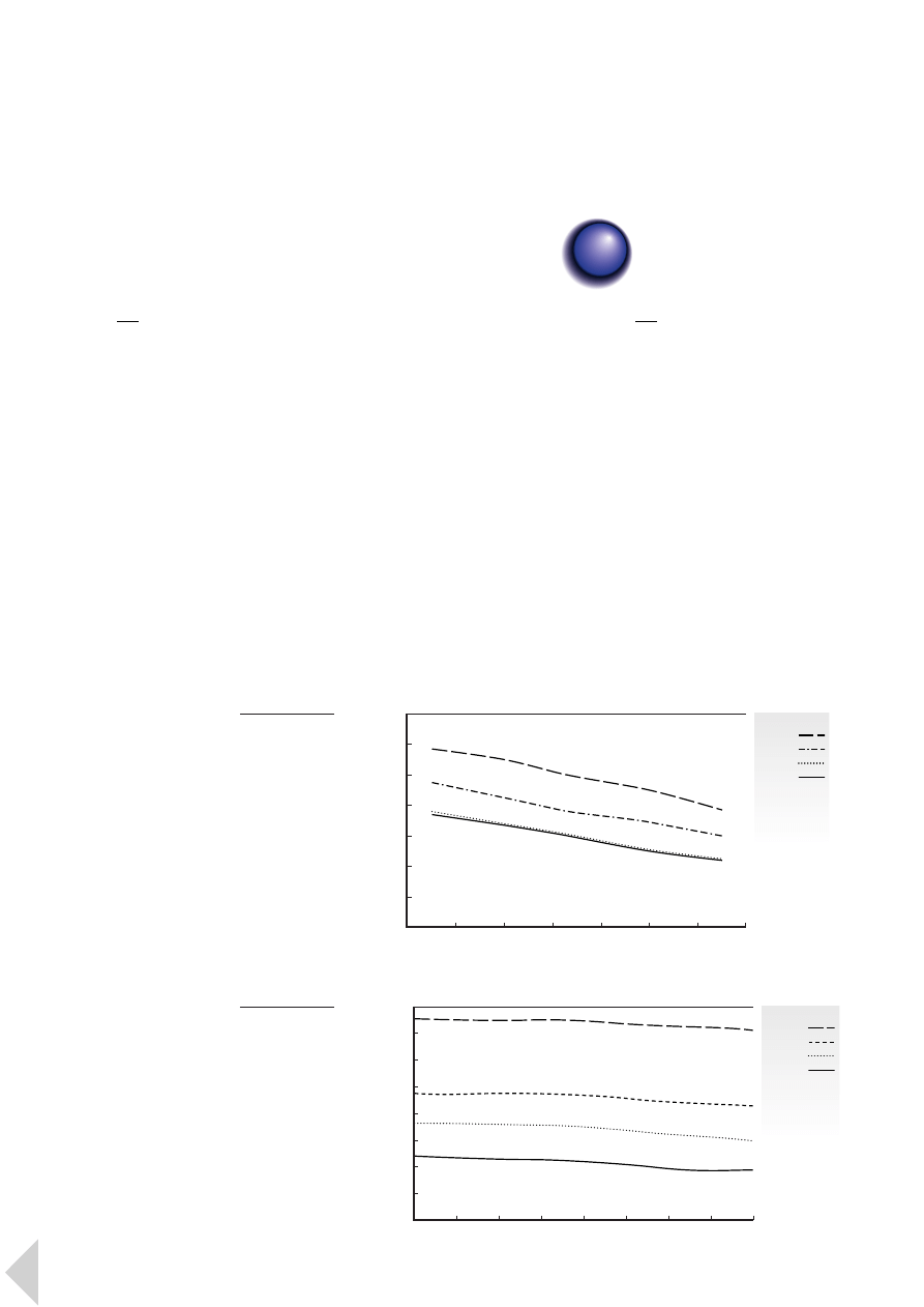
4.1
General properties
Lexan polycarbonate is an
amorphous engineering
thermoplastic which displays high
levels of mechanical, optical,
electrical and thermal properties.
Its unique property profile includes
outstanding impact strength over a
wide range of temperatures, from
subzero to over 80°C.
A characteristic Lexan resin offers:
·
High transparency
·
Extreme toughness
·
Low uniform shrinkage
·
Dimensional stability
·
Consistent processibility
·
UV stability
·
Flame retardancy
·
Heat resistance
·
Wide colour availability
Lexan resin’s exceptional impact
strength and practical toughness
establish it as a first choice material
for many very demanding
applications across diverse industries.
Design calculations for Lexan resin
are no different than for any other
material. Physical properties of plastic
are dependent on the expected
temperature and stress levels. Once
this dependency is understood, and
the end-use environment has been
defined for an application, standard
engineering calculations can be used
to accurately predict part
performance. However, in designing
for Lexan it is important to take
into account the notch sensitivity
and lower hydrolytic stability of
polycarbonate resins.
4.2
Mechanical properties
In general, Lexan resin exhibits
excellent mechanical property
retention over a wide temperature
range.
As illustrated in
■
F I G U R E S
1 and 2 ,
Lexan resin’s tensile strength and
flexural modulus decrease slightly as
temperature increases. However, the
effect of temperature on impact
resistance is the reverse: as the
temperature decreases, Lexan resin
becomes slightly stiffer and slightly
more brittle.
26
4
P r o p e r t i e s a n d D e s i g n
■
F I G U R E
1
Tensile strength
as a function
of temperature
Lexan
3414R
3412R
500R
141R
T
ensile str
ength (MPa)
Temperature (°C)
140
120
100
80
60
40
20
0
-40
-20
0
20
40
60
80
100
■
F I G U R E
2
Flexural modulus
of Lexan 3414R,
3412R, 500R and
141R as a function
of temperature
Lexan
3414R
3412R
500R
141R
Flexural modulus (MPa)
Temperature (°C)
8000
7000
6000
5000
4000
3000
2000
1000
0
-40
-20
0
20
40
60
80
100
120
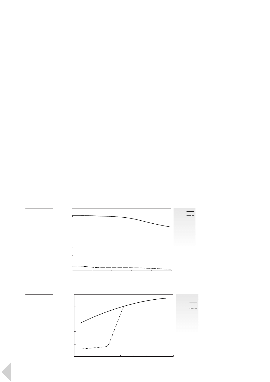
4.2.1
Impact strength
Lexan resin’s exceptional impact
strength and practical toughness
make parts virtually shatter-proof,
providing a high degree of safety and
durability in service in the toughest of
environments. The superior impact
resistance of Lexan polycarbonate
versus glass can be seen in
■
F I G U R E
3 .
At very low temperatures, impact
resistance can be further improved
by blending with other resins such
as ABS, as in Cycoloy
®
PC/ABS alloy,
or by blending with impact modifiers.
■
F I G U R E
4 , for example, compares
the Izod impact strength of impact
modified Lexan ML3400 resin with
a standard unmodified Lexan grade.
Lexan ML3459 resin offers superior
impact retention after painting with
various paint systems.
There are several factors which
determine the ability of a plastic part
to absorb impact energy.
In addition to the type of material
these factors include:
·
Wall thickness
·
Geometric shape and size
·
Operating temperature and
environment
·
Rate of loading
·
Stress state induced by loading
27
L e x a n P r o f i l e 4 P r o p e r t i e s a n d D e s i g n
■
F I G U R E
3
Tensile impact
of Lexan and glass
as a function of
temperature
Lexan
glass
T
ensile impact (KJ/m
2
)
Temperature (°C)
80
70
60
50
40
30
20
10
0
20
40
60
80
100
120
■
F I G U R E
4
Izod impact
strength of Lexan
as a function
of temperature
Lexan
impact
modified
standard
Izod notched impact (KJ/m
2
)
Temperature (°C)
100
80
60
40
20
0
-40
-30
-20
-10
0
10
20
30
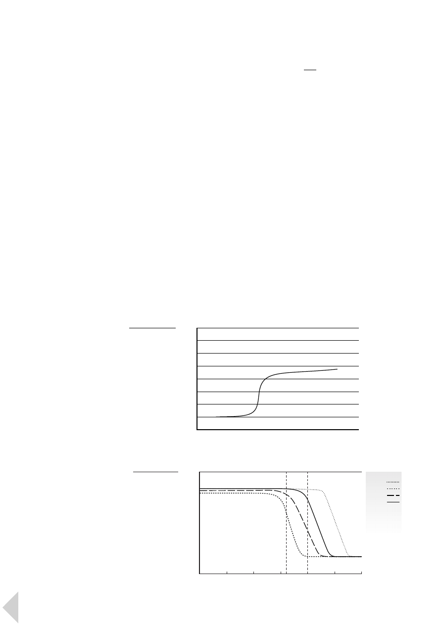
For ductile polymers such as Lexan
resin, the load at which yield occurs
in a part is affected by the last three
factors. Of even more significance
to design is the fact that, under the
appropriate circumstances, the
impact behaviour of a ductile
polymer will undergo a transition
from a ductile and forgiving response
to a brittle and catastrophic one.
Usually this change in behaviour is
described in terms of a transition
temperature above which the failure
is more ductile by nature, and below
which it is more brittle, as illustrated
in
■
F I G U R E
5 .
Interpretation of ISO & ASTM impact
values
Impact properties can be very
sensitive to test specimen thickness
and molecular orientation. The
differences in specimen thickness as
used in ASTM and ISO may have an
important effect on impact values.
A change from 3 to 4 mm thickness
can even provide a transition of the
failure mode from ductile to brittle
behaviour at a given temperature,
through the influence of molecular
weight and specimen thickness on
Izod notched impact. This is
illustrated in
■
F I G U R E
6 . Materials
which already exhibit a brittle
fracture mode at 3 mm, such as
mineral and glass-reinforced grades,
will not be affected. Impact modified
grades will also not be affected as they
still exhibit a ductile failure mode at
greater than 4 mm.
Therefore, ISO and ASTM impact
values may be radically different for
exactly the same material. However,
the ductile brittle transition described
rarely plays a role in real life as almost
all parts are designed with less than
3 mm wall sections.
4.2.2
Stiffness
The Lexan resin family offers
designers a great deal of choice as
far as stiffness is concerned.
While stiffness values can vary greatly
from one grade to another, the
stiffness properties for an individual
grade will remain constant over a
wide temperature range from subzero
to 120°C. In accordance with ISO 178,
the flexural modulus values range
from 2300 MPa for unreinforced
grades to up to 3400 MPa for 10%
glass-reinforced grades, 5500 MPa for
20% glass-reinforced, 7000 MPa for
30% glass-reinforced and 8500 MPa
for 40% glass-reinforced grades.
28
L e x a n P r o f i l e 4 P r o p e r t i e s a n d D e s i g n
■
F I G U R E
5
Graph illustrating
effect of
temperature upon
impact response
Impact value
Temperature
brittle behaviour
ductile behaviour
ductile/brittle transition
■
F I G U R E
6
Influence of
specimen
thickness and
molecular weight
on Izod notched
impact properties
of Lexan
Lexan
101
121
141
161
Izod notched impact
Specimen thickness (mm)
0
1
2
3
4
5
6
ASTM
ISO
3.2 mm 4.0 mm
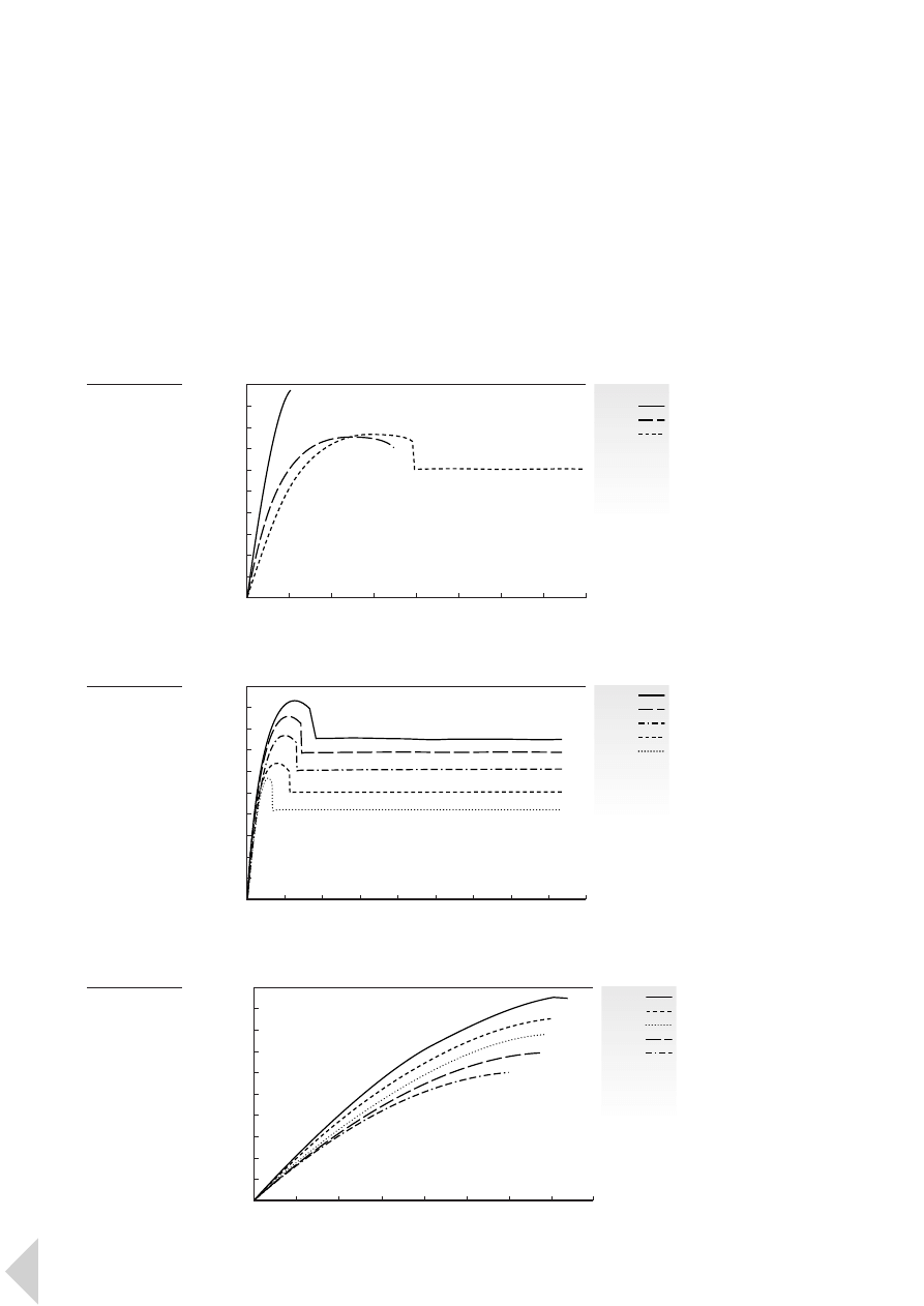
The stiffness of a part is defined as
the relationship between the load
and the deflection of a part. The
most important material property
for stiffness is the stress/strain curve.
In general, the Young’s modulus,
(ISO 527), which is determined from
the stress/strain curve, is the best
parameter to be used when
comparing the stiffness of materials.
■
F I G U R E
7 compares the tensile stress
and strain, showing modulus of
unreinforced Lexan 141R with 10%
glass-reinforced Lexan 500R and 20%
glass-reinforced Lexan 3412R. Lexan
500R shows an excellent combination
of energy absorption and modulus,
while Lexan 3412R has an ideal fit in
high modulus applications.
A further important consideration
in the calculation of part stiffness
is the temperature at which the
load is applied. As can be seen in
■
F I G U R E S
8 and 9 , the stress/strain
curves of thermoplastics are strongly
influenced by temperature.
29
L e x a n P r o f i l e 4 P r o p e r t i e s a n d D e s i g n
■
F I G U R E
7
Stress-strain
curve of Lexan
3412R, 500R
and 141R (23°C)
Lexan
3412R
500R
141R
T
ensile stress (MPa)
Strain (%)
80
72
64
56
48
40
32
24
16
8
0
0
2
4
6
8
10
12
14
16
■
F I G U R E
8
Stress-strain
curve of
Lexan 141R
-30°C
0°C
23°C
60°C
90°C
T
ensile stress (MPa)
Strain (%)
80
72
64
56
48
40
32
24
16
8
0
0
6
12
18
24
30
36
42
48
54
■
F I G U R E
9
Stress-strain
curve of
Lexan 3412R
-30°C
0°C
23°C
60°C
90°C
Stress (MPa)
Strain (%)
100
90
80
70
60
50
40
30
20
10
0
0
0.3
0.6
0.9
1.2
1.5
1.8
2.1
2.4
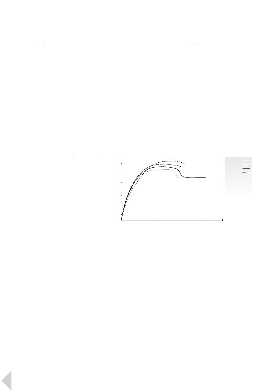
4.2.3
Strength
The strength of a part is defined as
the maximum load that can be
applied to a part without causing part
failure under given conditions.
In order to be able to determine the
strength of a part, failure has to be
first defined. The right definition of
failure depends on the application
and how much deformation is
allowed.
Material strength is a stress/strain
related property which is inherent
in the material. The tensile test
provides the most useful information
for engineering design. For unfilled
Lexan grades subjected to small
strains, the stress increases
proportionally with the strain.
However,early in the test non-linearity
will occur. In fact a close observation
of the stress/strain curve shows that a
proportional part does not exist. With
larger strains, yield will occur and the
maximum stress is reached. If the
strain is further increased, necking
will occur. The neck will propagate
through the structure until the
material fails.
The speed of deformation in the
application is vital. The differences
are shown for Lexan 500R in
■
F I G U R E
1 0 .
4.2.4
Behaviour over time
There are two types of phenomena
which should be considered. Static
time dependent phenomena such
as creep are caused by the single,
long-term loading of an application.
Dynamic time dependent
phenomena such as fatigue, on the
other hand, are produced by the
cyclic loading of an application.
Both types of behaviour are heavily
influenced by the operating
environment and component design.
30
L e x a n P r o f i l e 4 P r o p e r t i e s a n d D e s i g n
■
F I G U R E
1 0
Stress-strain
curve of
Lexan 500R (23°C)
10 %/sec
1 %/sec
0.1 %/sec
0.01 %/sec
Stress (MPa)
Strain (%)
70
63
56
49
42
35
28
21
14
7
0
0
2
4
6
8
10
12
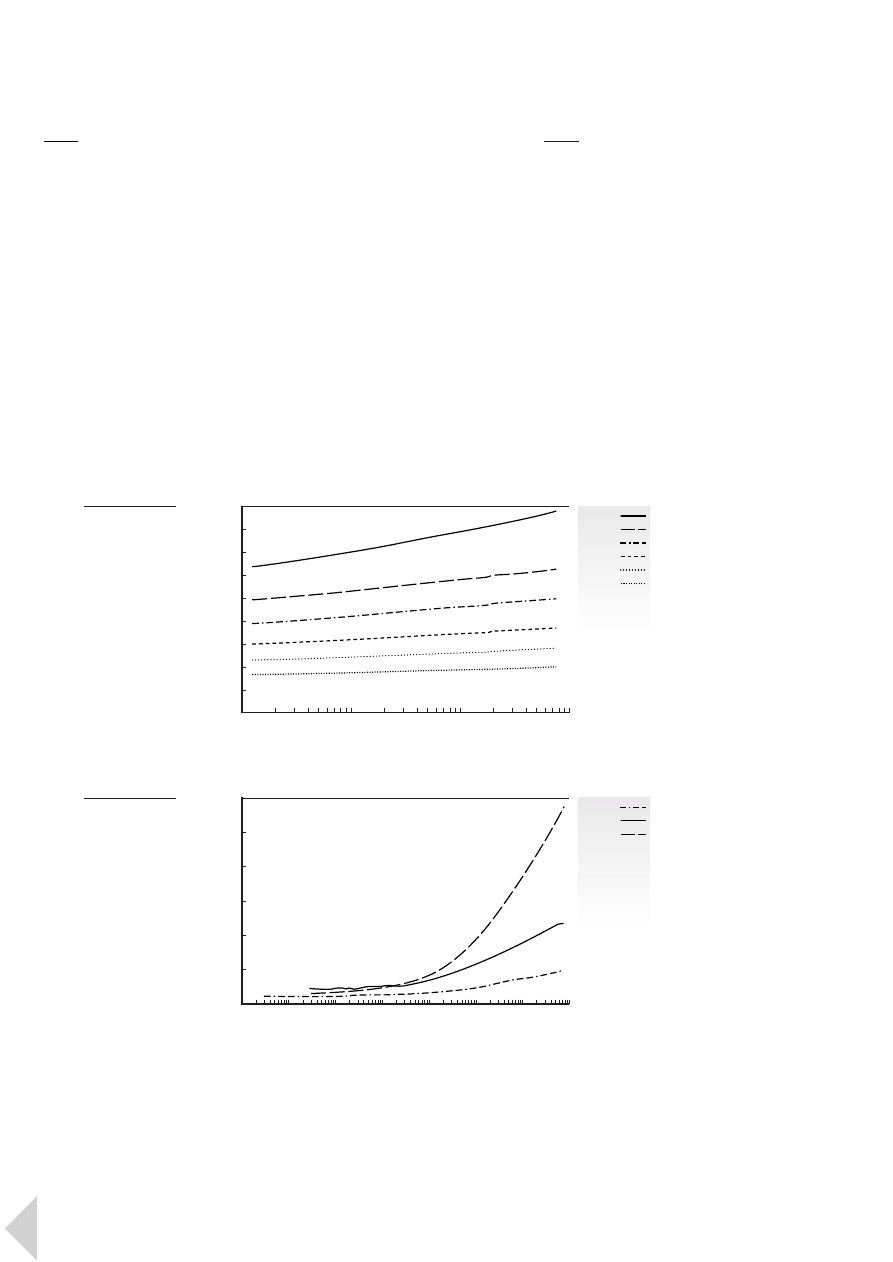
4.2.4.1
Creep behaviour
Creep is defined as the increasing
rate of deformation of a geometrical
shape when subjected to a constant
long-term load. With plastics,
the creep rate is dependent on
temperature, load and time. At a
certain stress level, creep becomes
minimal and can be disregarded
in long-term, continuous-load
applications.
■
F I G U R E
1 1 shows that a key property
of Lexan resin is its predictable, low
creep behaviour even at higher loads.
This is due to the amorphous
structure and its inherent high heat
resistance. At higher temperatures,
the creep behaviour is increased as
can be seen in
■
F I G U R E
1 2 .
4.2.4.2
Fatigue endurance
Fatigue is an important design
consideration for parts subjected to
cyclic loading or vibration. Structural
components subjected to vibration,
components subjected to repeated
impacts, reciprocating mechanical
components, plastic snap-fit latches
and moulded-in plastic hinges are all
examples where fatigue can play an
important role. Cyclic loading can
result in mechanical deterioration
and fracture propagation through the
material, leading to ultimate failure.
When parts are subjected to cyclic
loading, fatigue failure can occur,
often at a stress level considerably
below the yield point of the material.
31
L e x a n P r o f i l e 4 P r o p e r t i e s a n d D e s i g n
■
F I G U R E
1 1
Deformation at
constant load
(creep) of Lexan
141R (23°C)
Strain (%)
Time (hrs)
3.6
3.2
2.8
2.4
2.0
1.6
1.2
0.8
0.4
0
10
0
10
1
10
2
10
3
40 MPa
35 MPa
30 MPa
25 MPa
20 MPa
15 MPa
■
F I G U R E
1 2
Deformation at
constant load
(creep) of Lexan
141R (15 MPa)
Strain (%)
Time (hrs)
1.8
1.6
1.4
1.2
1.0
0.8
0.6
10
-4
10
-3
10
-2
10
-1
10
0
10
1
10
2
10
3
23°C
60°C
90°C
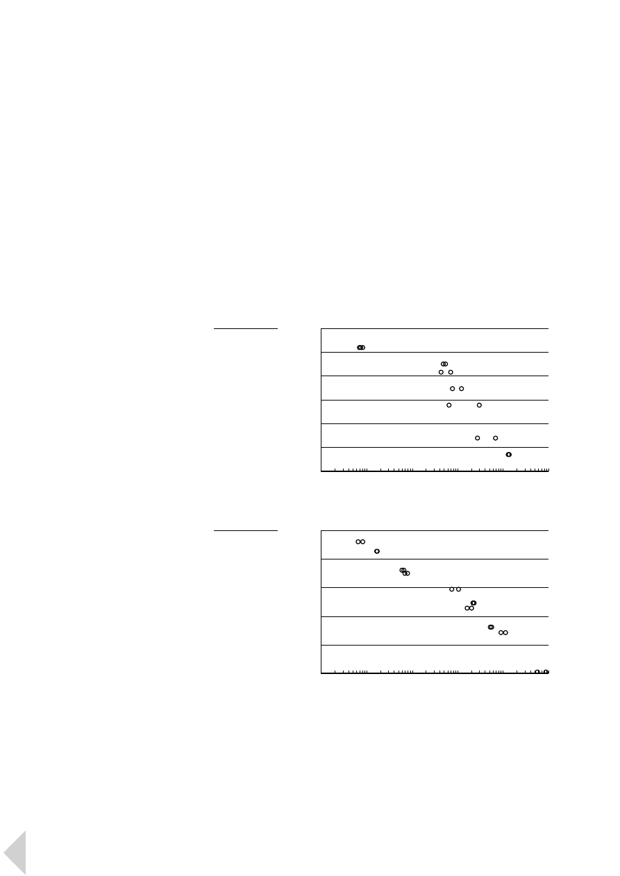
In such applications, an uniaxial
fatigue diagram could be used to
predict product life. These curves
can be used to determine the fatigue
endurance limit, or the maximum
cycle stress that a material can
withstand without failure.
■
F I G U R E S
1 3 and 1 4 compare the
fatigue behaviour of an unfilled and
a filled Lexan grade.
Fatigue tests are usually conducted
under flexural conditions, though
tensile and torsional testing is also
possible. A specimen of material is
repeatedly subjected to a constant
deformation at a constant frequency,
and the number of cycles to failure
is recorded. The procedure is then
repeated over a range of deflections
or applied stresses. The test data are
usually presented as a plot of log
stress versus log cycles; this is
commonly referred to as an S - N
curve, as shown in
■
F I G U R E S
1 3
and 1 4 . S - N curves obtained under
laboratory conditions may be
regarded as “ideal”. However,
practical conditions usually
necessitate the use of a modified
fatigue limit, as other factors may
affect performance, including most
notably the type of loading, the size
of the component and the loading
frequency.
However, fatigue testing can only
provide an indication as to a given
material’s relative ability to survive
fatigue. It is therefore essential that
tests are performed on actual
moulded components, under actual
end-use operating conditions.
32
L e x a n P r o f i l e 4 P r o p e r t i e s a n d D e s i g n
■
F I G U R E
1 3
Uniaxial fatigue
test of Lexan 141
(frequency 5 Hz,
23°C)
Stress (MPa)
Cycles to failure
70
60
50
40
30
20
10
10
2
10
3
10
4
10
5
10
6
10
7
■
F I G U R E
1 4
Uniaxial fatigue
test of Lexan 500R
(frequency 5 Hz,
23°C)
Stress (MPa)
Cycles to failure
70
60
50
40
30
20
10
1
10
2
10
3
10
4
10
5
10
6
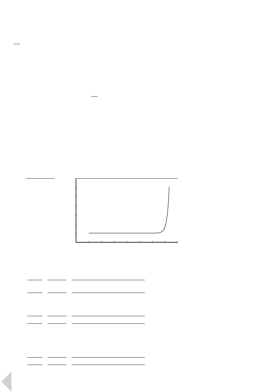
4.3
Thermal properties
The property profile of Lexan
resin includes very good thermal
properties.
However, all thermoplastics will
soften at elevated temperatures.
The most common thermal test is
the Vicat Softening Temperature,
as shown in
■
F I G U R E
1 5 , which
measures the temperature at which
a plastic starts to soften rapidly.
A second commonly used thermal test
is the Heat Deflection Temperature,
which in amorphous materials such as
Lexan resin is strongly related to the
glass transition temperature ( T
g
).
Other thermal tests include the Ball
Pressure Test, IEC 695-10-2,
according to which almost all Lexan
resins pass at 125°C.
In accordance with UL746B, Lexan
resins have been granted a Relative
Thermal Index (RTI) of between
80°C and 130°C. There can be up to
three independent RTI ratings
assigned to a material: electrical,
mechanical with impact and
mechanical without impact.
4.4
Flammability
Non-flame retarded standard Lexan
resins in addition to the flame
retarded Lexan 500 and 900 series all
offer halogen-free flame retardancy
according to DIN VDE 472, part 815.
The most widely accepted
flammability performance standards
for plastics are UL ratings which
identify a material’s ability to
extinguish a flame once ignited.
According to UL Subject 94, the
Lexan 900 series has been rated V0 at
low thicknesses (e.g. 943 is UL94 V0
at 1.04 mm), Lexan 3412R is rated V0
at 0.8 mm, while the Lexan 500 series
has been rated V0 at 1.5 mm and 5VA
at 3 mm. A complete overview of the
UL 94 classifications for Lexan is
given in
■
TA B L E
1 . It should be noted
that each Lexan resin tested may
receive several ratings depending on
colour and/or thickness.
In addition, Glow Wire Test results,
according to IEC 695-2-1, are
dependent on the thickness of the
material sample and the actual test
temperature. Almost all Lexan grades
pass the 850°C test at 1 mm, while
most of the flame retarded grades will
pass the 960°C test at 1.6 mm. Special
grades are available which pass the
960°C test at 1 mm.
33
L e x a n P r o f i l e 4 P r o p e r t i e s a n d D e s i g n
■
F I G U R E
1 5
Vicat indentation
vs. temperature
of Lexan 161R
(ISO 179; Shear
rate: 120°C/hr;
weight: 50 N)
Indentation (mm)
Temperature (°C)
1.2
1.0
0.8
0.6
0.4
0.2
0
-0.2
0
20
40
60
80
100
120
140
160
UL rating
Thickness
Lexan grades
UL94 HB
< 1.5 mm
103R, 123R, 143R, 163R, LS1, LS2, LS3, ML3322
1.5 - 3.0 mm
1xy series, ML3021A, ML3324
UL94 V2
< 1.5 mm
201R, 221R, 261R, HF1110R, HF1140R,
ML3021A, ML3041
1.5 - 3.0 mm
2014R, 2034, 2xy series, 910A, 920A, 940A,
950A, 923A, 943A, 953A, ML3290, ML3485
UL94 V1
1.5 - 3.0 mm
1278R, ML3260
UL94 V0
< 1.5 mm
3412, 923, 940, 943
1.5 - 2.5 mm
2814R, 3413R, 500R, 503R, 920, 950,
ML3290, ML3513
> 2.5 mm
2014R, 2034, 910A, 920A, 940A, 943A, 950A,
953A, ML3260
> 4.0 mm
FL900P
UL94 5VA
> 3.0 mm
500R, 503R, 950
■
TA B L E
1
UL recognition for flammability
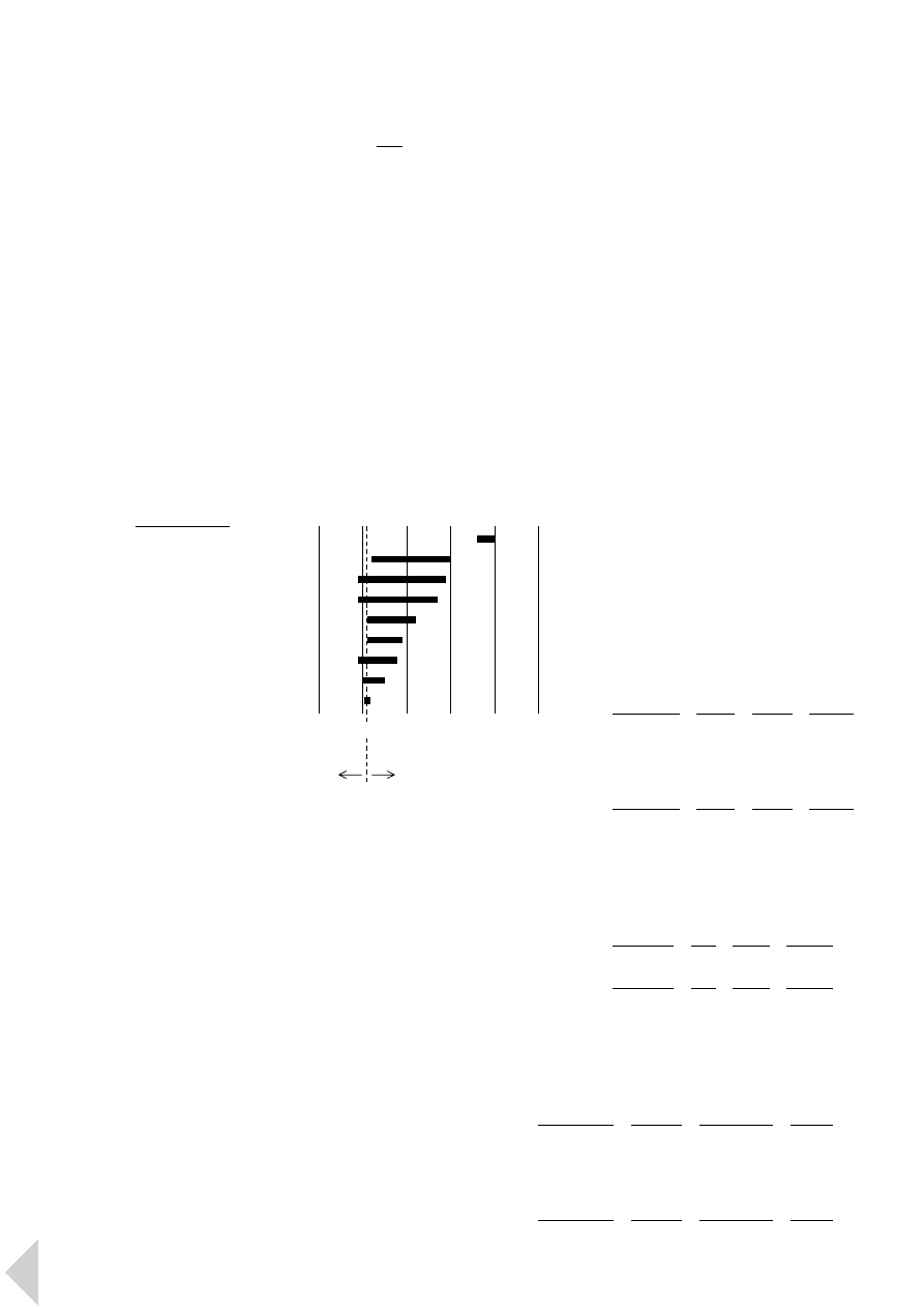
In accordance with ISO 4589, Lexan
general purpose grades have a limited
oxygen index (LOI) of 25 - 28%, while
Lexan 900A grades have an LOI of
38%. This means that all Lexan resins
are self-extinguishing.
■
F I G U R E
1 6
compares the LOI of various GE
Plastics’ resins.
This combination of properties makes
Lexan resin an ideal material for a
variety of electrotechnical
applications.
4.4.1
Transportation industry
regulations
Lexan resin is widely used in a variety
of transportation applications.
Stringent flammability requirements
are enforced depending on the
industry and the country.
In railway industry applications in
France, for example, the I, F, M
classification according to
NF F 16-101 is important, while in
Germany applications are subject to
DIN 5510. Typical values for Lexan
for both regulations are given in
■
TA B L E S
2 and 3 , with the
understanding that these values
can be thickness and/or colour
dependent.
In aircraft applications, Lexan resin’s
compliance with the requirements of
Airbus standard ABD0031 for smoke
evolution and toxicity is detailed in
■
TA B L E
4 .
According to the federal motor
vehicle safety standard FMVSS302,
all Lexan grades pass at thicknesses
>1.5 mm, while flame retarded
grades even pass at thicknesses below
1.5 mm.
34
L e x a n P r o f i l e 4 P r o p e r t i e s a n d D e s i g n
■
F I G U R E
1 6
Limited oxygen
index (ISO 4589)
Ultem *
Lexan
Noryl
Valox
Cycoloy
Noryl GTX
Cycolac
Noryl Xtra
Xenoy
→
%
10
20
30
40
50
60
*
inherent flame redardancy
burns
extinguishes
21 % O
2
in air
I-class
F-class
M-class
Lexan 2034
I2
F2
M2
Lexan 2814R
I2
F2
M2
Lexan 500R
I3
F1
–
Lexan 943
I3
F1
–
Lexan 943A
I2
F1
–
■
TA B L E
2
Typical values for Lexan according to
transportation industry regulation NF F 16-101
FAR25853
Smoke D4min
Toxicity
Lexan 500R
b
< 200
pass
Lexan 940
b
< 200
pass
Lexan 950
b
< 200
pass
Lexan 950A
b
< 200
pass
Lexan ML3290
b
< 200
pass
■
TA B L E
4
Typical values for Lexan according to
Airbus standard ABD0031
Fire
Smoke
Dripping
Lexan 503R
S3
SR2
ST2
Lexan 923
S3
SR2
ST2
■
TA B L E
3
Typical values for Lexan according to
transportation industry regulation DIN5510
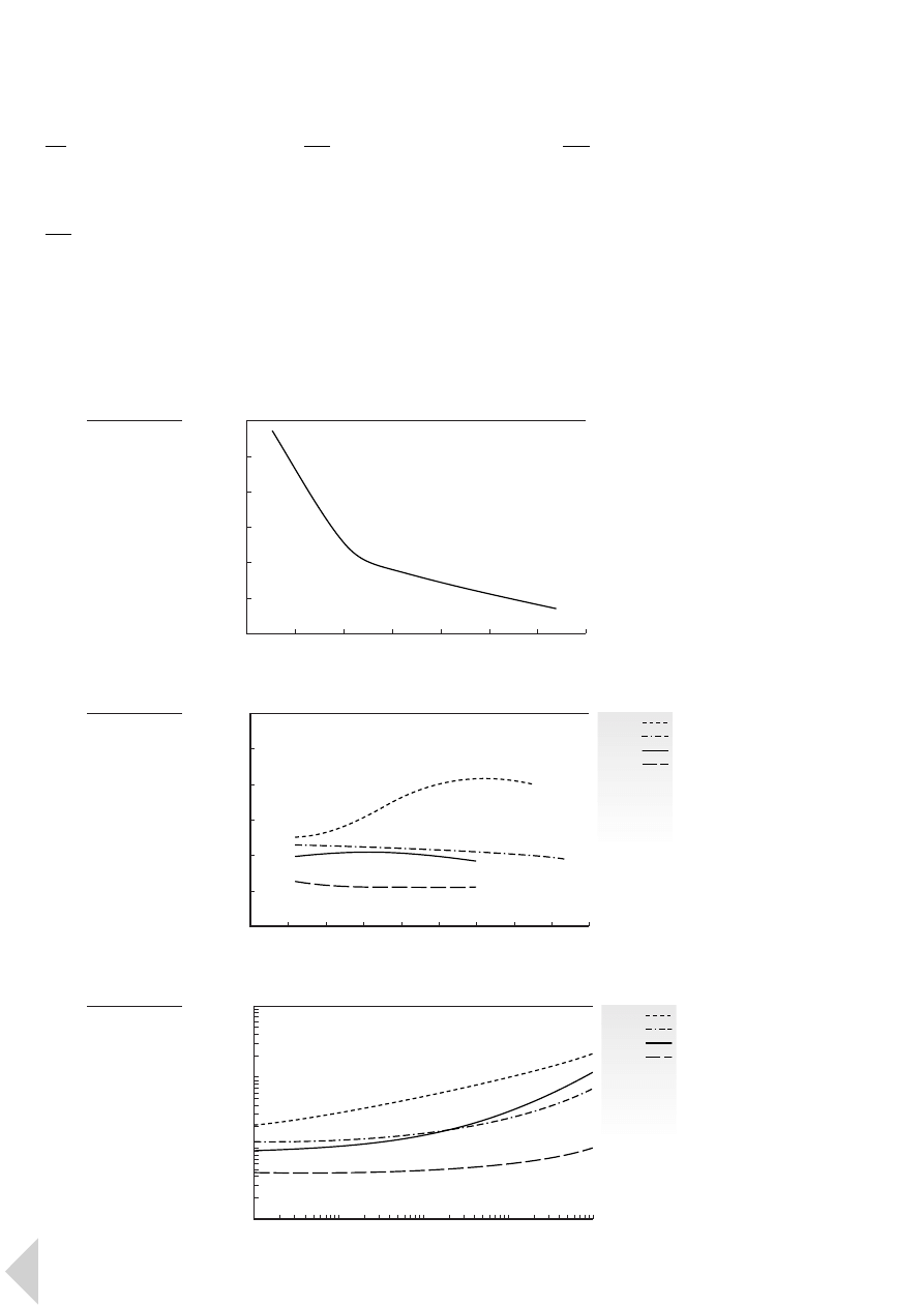
4.5
Electrical properties
As an organic material, Lexan resin
is an excellent electrical insulator.
4.5.1
Dielectric strength
As can be seen in
■
F I G U R E
1 7 , the
dielectric strength is non-linear with
the thickness. Standard Lexan resin
typically exhibits a dielectric strength
of 17 kV/mm at 3.2 mm, 27 kV/mm at
1.5 mm, 35 kV/mm at 1 mm and
67 kV/mm at 0.25 mm thickness.
4.5.2
Relative permittivity
■
F I G U R E
1 8 shows that the relative
permittivity values of Lexan resins are
intermediate to high when compared
with other polymers. The higher
values indicate a greater insulating
quality.
4.5.3
Dissipation factor
As can be seen in
■
F I G U R E
1 9 , the
electrical dissipation factor of Lexan
resins over a wide range of
frequencies varies from intermediate
to high when compared with other
polymers; the smaller values for the
dissipation factor correspond to a
better dielectric material. In addition
to frequency, temperature and
contaminants such as moisture affect
the dissipation factor.
35
L e x a n P r o f i l e 4 P r o p e r t i e s a n d D e s i g n
■
F I G U R E
1 8
Relative
permittivity at
60Hz and 50%
RH of unfilled
materials
Valox
Ultem
Lexan
Noryl
Valox
Ultem
Lexan
Noryl
Dielectric constant
Temperature (°C)
5.0
4.5
4.0
3.5
3.0
2.5
2.0
0
20
40
60
80
100
120
140
160
180
■
F I G U R E
1 9
Dissipation factor
at 23°C of unfilled
materials
Dissipation factor
Frequency (Hz)
10
-1
10
-2
10
-3
10
-4
10
2
10
3
10
4
10
5
10
6
■
F I G U R E
1 7
Dielectric
strength of
unfilled Lexan
as a function
of thickness
Dielectric str
ength (kV/mm)
Thickness (mm)
70
60
50
40
30
20
10
0
0.5
1
1.5
2
2.5
3
3.5
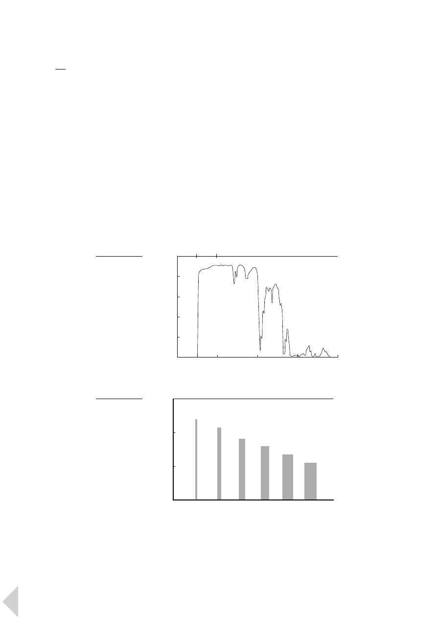
4.6
Aesthetics and optical
properties
Lexan resin is a naturally transparent,
‘water white’ material with excellent
aesthetic properties. It is available in
a wide choice of colours, many of
which have transparent, translucent,
opalescent and opaque versions.
In addition, Lexan resin consistently
reproduces mould surface finish
with great accuracy. This provides
designers with top quality, high gloss
or textured surface finishes.
Lexan resin has excellent light
transparency which is close to that of
glass, and a very high refractive index
of 1.586. Its highest transmission rate
is in the visible light and infrared
region, as shown in
■
F I G U R E
2 0 .
■
F I G U R E
2 1 shows the excellent light
transmission of standard natural
colour Lexan 141R resin at different
thicknesses. The light transmission
of transparent Lexan resins can be
changed if required. Grades such as
Lexan 143R-111 and Lexan LS2-111
have a built-in UV screen to filter out
UV radiation up to 380 nm. Modified
grades such as Lexan OQ4320 will
even reach 400 nm, thereby providing
additional sun protection without
affecting the transmission in the
36
L e x a n P r o f i l e 4 P r o p e r t i e s a n d D e s i g n
280 - 315 nm
UV-B middle UV region
315 - 280 nm
UV-A middle UV region
380 - 780 nm
visible light region
780 - 1400 nm
near infra red region
1400 - 3000 nm
middle infra red region
■
F I G U R E
2 0
Light transmission
of UV stabilized
Lexan
Light transmission (%)
Wavelength (nm)
100
80
60
40
20
0
0
800
1600
2400
3200
UV
visible
infra red
■
F I G U R E
2 1
Light transmission
of Lexan 141R
as a function
of thickness for
standard natural
colour
T
ransmission (%)
92
90
88
86
1 mm
2 mm
3 mm
4 mm
5 mm
6 mm
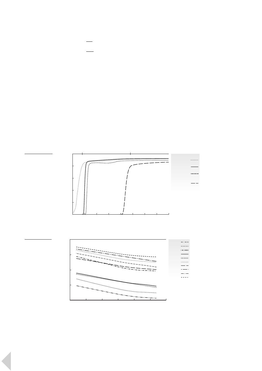
visible region. Special colours provide
a high light transmission in the
infrared region only, which blocks all
light in the visible light region for
applications such as remote control
panels, as illustrated in
■
F I G U R E
2 2 .
Opalescent colours provide partial
light diffusion for the Lighting
Industry. The transmission at a given
thickness is critical. Lexan resins can
be produced in a wide range of
opalescent colours with different
transmission values, as shown in
■
F I G U R E
2 3 .
4.7
Environmental resistance
4.7.1
Chemical resistance
Lexan resin can be adversely affected
by certain combinations of chemical
environment, temperature and stress.
For this reason, lubricants, gaskets,
O-rings, cleaning solvents or any
material which may come into contact
with the finished part should be
carefully evaluated for compatibility.
In all cases extensive testing of the
finished part under actual service
conditions is strongly recommended.
The performance and interpretation
of the results of end-use testing are
the end-producer’s responsibility.
While Lexan generally displays good
property retention when exposed to
water, mineral acids and organic
acids, crazing and/or embrittlement
may occur if the Lexan resin part is
highly stressed and exposed to hot
water or a humid environment.
Lexan resin is insoluble in aliphatic
hydrocarbons, ethers and alcohols.
It is partly soluble in aromatic
hydrocarbons, soluble in chlorinated
hydrocarbons and will slowly
decompose in strong alkaline
solutions.
■
TA B L E
5 (see next page)
provides a comprehensive overview of
the chemical compatibility of Lexan
resin according to the specified
GE Plastics test conditions.
37
L e x a n P r o f i l e 4 P r o p e r t i e s a n d D e s i g n
■
F I G U R E
2 2
Light transmission
of transparent
Lexan
Lexan
141R
non-UV stabilized
LS2
UV stabilized
OQ4320
UV stabilized with
400 nm cut-off
121R
‘infra red’ colour
T
ransmission (%)
Wavelength (nm)
100
80
60
40
20
0
300
400
500
600
700
800
900
1000 1100
UV
visible
infra red
■
F I G U R E
2 3
Transmission of
Lexan opalescent
colours as a
function of
thickness
82025
82027
82046
82052
82062
82082
82103
82227
82253
82268
T
ransmission (%)
Thickness (mm)
85
70
55
40
25
1.5
1.8
2.1
2.4
2.7
3.0
3.3

Acid, mineral
Boric acid
+
Hydrogen chloride 20%
+
Hydrogen chloride 25%
–
Hydrogen fluoride 25%
+
Nitric acid 70%
–
Perchloric acid
–
Phosphorus pentoxide dry
+
Phosphoric acid 1%
+
Phosphoric acid 10%
–
Phosphorus pentachloride
+
Sulphuric acid 50%
+
Sulphuric acid 70%
–
Sulphurous acid 5%
–
Acid, organic
Acetic anhydride
–
Formic acid concentrate
–
Gallic acid
+
Malelc acid
+
Mercapto acetic acid
–
Murstic acid 20%
+
Muristic acid 25%
–
Olelc acid
+
Palmitic acid
+
Phenol sulphonic acid
–
Phenoxyacetic acid
+
Phthallic anhydride
+
Salycilate acid
+
Tannic acid
+
Tannic acid 20%
–
Thiodiacetic acid
+
Trichlor acetic acid
–
Sulphamine acid 5%
0
Alcohol
Allyl alcohol
–
Amyl alcohol
–
Butoxyethanol
–
Chlorethanol 2
–
Decyl alcohol
–
Dodecyl alcohol
–
Ethanol
–
Ethyl glycol 100%
–
Ethyl glycol 60%
+
Furfuryl alcohol
–
Glycerine
+
Hepthyl alcohol
–
Isobutanol
0
Nonyl alcohol
–
Octyl alcohol
+
Oxydiethanol 2.2
+
Phenetyl alcohol
–
Polyalkylene glycol
–
Polyethylene glycol
+
Propylene glycol
–
Sorbitol
+
Thiodiglycol 5%
–
Triethylene glycol
+
Tripropylene glycol
–
Aldehide
Acetaldehyde
–
Butyraldehyde
–
Formaldehyde solvent 37%
+
Formalin
+
Propionaldehyde
–
Amide
Dimethylformamide
–
Amine
Aniline
–
Diphenylamine
–
Methylaniline N
–
Methylene dianiline
–
Phenylhydrazine
–
Pyridine
–
Triethanolamine
+
Hydroxylamine
+
Base
Aluminium hydroxine powder
+
Ammonia concentrate
–
Ammonium hydroxide 0.13%
–
Calcium hydroxide
–
Potassium hydroxide 10%
–
Sodium hydroxide dry
+
Sodium hydroxide 10%
–
Sodium thotalamate
+
Ester
Benzyl benzoate
–
Buthyl cellosolve acetate
–
Buthyl stearate
–
Cello acetobutyrate
–
Cellulose acetate
–
Cellulose proprionate
–
Dibuthyl phthalate
–
Didecyl carbonate
–
Disodecyl phthalate
–
Disononyl phthalate
+
Dioctyl phtalate
–
Dioctyl sebacate
–
Ditridecyl carbonate
–
Ditridecyl phthalate
–
Ethyl bromoacetate
+
Ethyl butyrate
–
Ethyl cellusolve 5%
–
Ethyl chloracetate
–
Ethyl cyanoacetate
–
Ethyl lactate
–
Ethyl salicilate
–
Isopropyl myristrate
–
Methyl acetate
+
Methyl calicylate
–
Methylbenzoate
–
Triacetine
–
Tributoxethyl phosphate
–
Tributyl cello phosphate
–
2 dodecyl phenyl carbonate
+
Ether
Ether
–
Ethyl cellosolve 5%
–
Methyl cellosolve
–
Polyalkylene glycol
–
Polyethylene glycol
+
Polyethylene sulfide
–
Propylene oxide
–
Gaseous
Ammonia concentrate
–
Bromine
–
Chloracetophenone
–
Chlorine
–
Iodine
–
38
L e x a n P r o f i l e 4 P r o p e r t i e s a n d D e s i g n
This overview shows the chemical resistancy of Lexan polycarbonate
sheet. Chemical compatibility of thermoplastics e.g. Lexan is dependent
on contact time, temperature and stress (external stress to which the
application is subjected). Chemical exposure can result in discolouration,
softening, swelling, crazing, cracking or loss of properties of the
thermoplastic. The chemicals listed have been evaluated for Lexan
according to a very stringent GE Plastics test method. This test
incorporates exposure to the chemical under defined conditions including
temperature (20°C and 80°C) and stress (0.5% and 1% strain) for a time
period of seven days.
This information should be used as indicative only. The true chemical
compatibility can only be determined under conditions as in the final
application. Please contact your local representative in case additional
information is required.
■
TA B L E
5
Chemical compatibility of Lexan polycarbonate
Key to performance
– poor, not recommended; will result in
failure or severe degradation
0 fair, found marginal; only for short
exposures at lower temperatures or when
loss of properties is not critical
+ good; found unaffected in its performance
when exposed with regards to time,
temperature and stress according
the GE Plastics test method

Isobutane
–
Methane
–
Oxygen
+
Ozone 2%
–
Propylene
+
Sulphur dioxide
–
Sulphur hexafluoride
–
Halogenated HC
Acetylene dibromo
–
Acetylene tetrabromide
–
Bromochloromethane
–
Carbon tetrachloride
–
Chlorethanol 2
–
Chlorobenzene
–
Chlorobutane
–
Chloroform
–
Dibromomethane
–
Dichloroethane
–
Dichlorohydroxybenzene
+
Dichloromethane
–
Ethyl bromoacetate
+
Ketone
Methyl ethyl ketone
–
Metal & metal oxide
Aluminium oxide
+
Arsenic trioxide
–
Calcium oxide paste
–
Cuprous oxide
+
Mercury metallic
–
Phenol
Allyl 4 methoxyphenol
–
Cresol
–
P-Phenylphenol
–
Pentachlorophenol
–
Phenol sulphonic acid
–
Phenol 5%
–
Phenoxyacetic
+
Salt, inorganic
Aluminium ammonium sulphate
–
Aluminium chloride
–
Aluminium floride
+
Aliminium potassium sulphate
–
Aluminium sodium sulphate
+
Ammonium bicarbonate
+
Ammonium bromide
+
Ammonium carbonate
–
Ammonium dichromate
+
Ammonium persulfate
+
Arsenic trioxide
–
Barium carbonate
+
Barium chloride
+
Barium sulphate
+
Calcium carbonate paste
–
Calcium chloride
+
Calcium sulphate
+
Cesium bromide
+
Copper (II) chloride 5%
+
Iron (II) chloride
–
Iron (III) ammonium sulphate
+
Iron (III) chloride saturated
+
Iron (III) nitrate
–
Iron (III) sulphate
+
Lithium bromide
+
Lithium hydroxide powder
+
Magnesium bromide
+
Magnesium chloride
+
Magnesium nitrate
+
Magnesium sulphate
+
Mercury (I) nitrate
+
Mercury (II) chloride
–
Mono ammonium phosphate
+
Nickel nitrate
+
Potassium bicarbonate dry
+
Potassium bisulphate
+
Potassium bromate
+
Potassium bromide
+
Potassium carbonate
+
Potassium chlorate
+
Potassium chloride saturated
–
Potassium chloride 15%
+
Potassium chormium sulphate
–
Potassium cyanide powder
+
Potassiun dichromate
+
Potassium iodide
+
Potassium nitrate
+
Potassium permaganate
–
Potassium persulphate
+
Potassium sulphate
+
Silver chloride saturated
–
Silver nitrate
+
Sodium bicarbonate saturated
0
Sodium bicarbonate 13%
–
Sodium bisulphate
+
Sodium bromate
+
Sodium bromide
+
Sodium carbonate
+
Sodium carbonate solvent
–
Sodium chlorate
+
Sodium etherlaurysulphate
0
Sodium ferrycyanide
+
Sodium fluoride
+
Sodium hypochlorite 6%
+
Sodium hypochlorite 15%
–
Sodium nitrate 10%
–
Sodium perborate
+
Sodium phosphate
+
Sodium sillicate
+
Sodium sulphide
–
Sodium sulphite
+
Strontium bromide
+
Tin (II) chloride
+
Tin (IV) chloride
+
Titanium tetrachloride
+
Trisodium phosphate 5%
–
Zinc bromide
+
Zinc carbonate
+
Zinc chloride
–
Zinc oxyde
–
Zinc sulphate
+
Salt, organic
Alluminium acetate
+
Ammonium acetate
–
Ammonium oxalate
+
Aniline sulphate
+
Potassium acetate 30%
–
Qulnine sulphate
–
Sodium acetate 30%
–
Valine bromide dl
+
39
L e x a n P r o f i l e 4 P r o p e r t i e s a n d D e s i g n
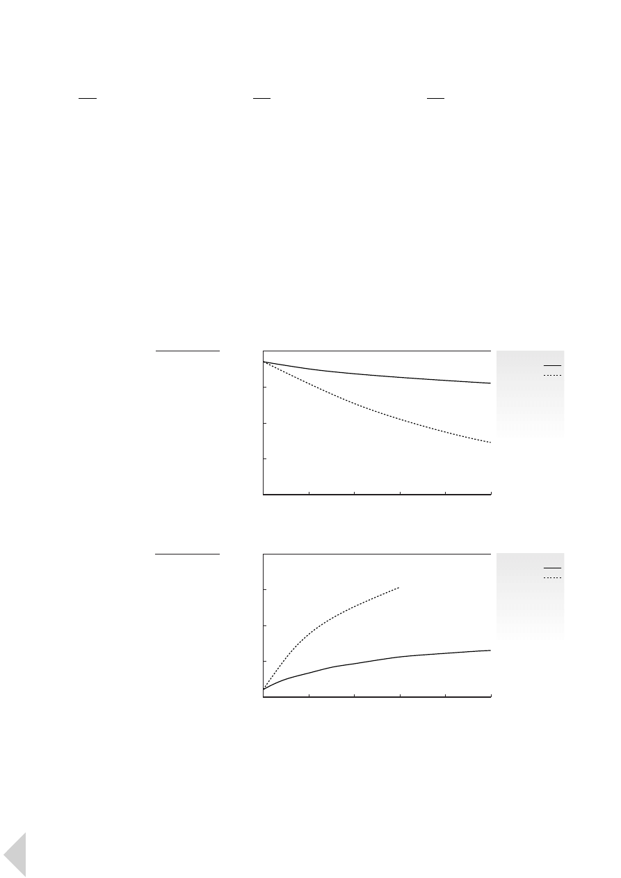
4.7.2
Sterilization
Lexan polycarbonate meets the
requirements of the FDA and USP
Chapter XXII Class V1 for use in the
medical industry where it is used for a
wide range of equipment which must
be sterilized. This can be achieved by
all three commonly used methods:
gamma radiation, EtO gas and steam
(autoclave). Tailor-made Lexan GR
grades provide superior colour
stability and resistance to yellowing
following gamma or EtO sterilisation.
4.7.3
Cleaning and degreasing
Cleaning or degreasing of Lexan
resin finished parts can be performed
using methyl or isopropyl alcohol,
mild soap solutions, heptane or
hexane. The parts should not be
cleaned with partially hydrogenated
hydrocarbons, with ketones such as
MEK, with strong acids or with
alkalines such as sodium hydroxide.
4.7.4
Ultraviolet exposure
Lexan resin may be sensitive to long-
term exposure to ultraviolet light and
weathering. The degree of sensitivity
is very much dependent on the
specific grade, the specified colour
and the weathering conditions.
Lexan resins are ideally suited to a
range of both indoor and outdoor
applications.
■
F I G U R E S
2 4 and 2 5
show that UV stabilized Lexan grades
maintain high light transmission after
prolonged UV exposure and offer a
good resistance to yellowing after
prolonged exposure to harsh climatic
conditions.
40
L e x a n P r o f i l e 4 P r o p e r t i e s a n d D e s i g n
■
F I G U R E
2 5
Yellowness index
of transparent
Lexan after
natural exposure
acc. ASTM G7,
at Florida (USA)
Y
ellowness index
Exposure (years)
40
30
20
10
0
0
1
2
3
4
5
■
F I G U R E
2 4
Transmittance
of transparent
Lexan after
natural exposure
acc. ASTM G7,
at Florida (USA)
Lexan
UV stabilized
non stabilized
Lexan
UV stabilized
non stabilized
T
ransmittance (%)
Exposure (years)
90
80
70
60
50
0
1
2
3
4
5
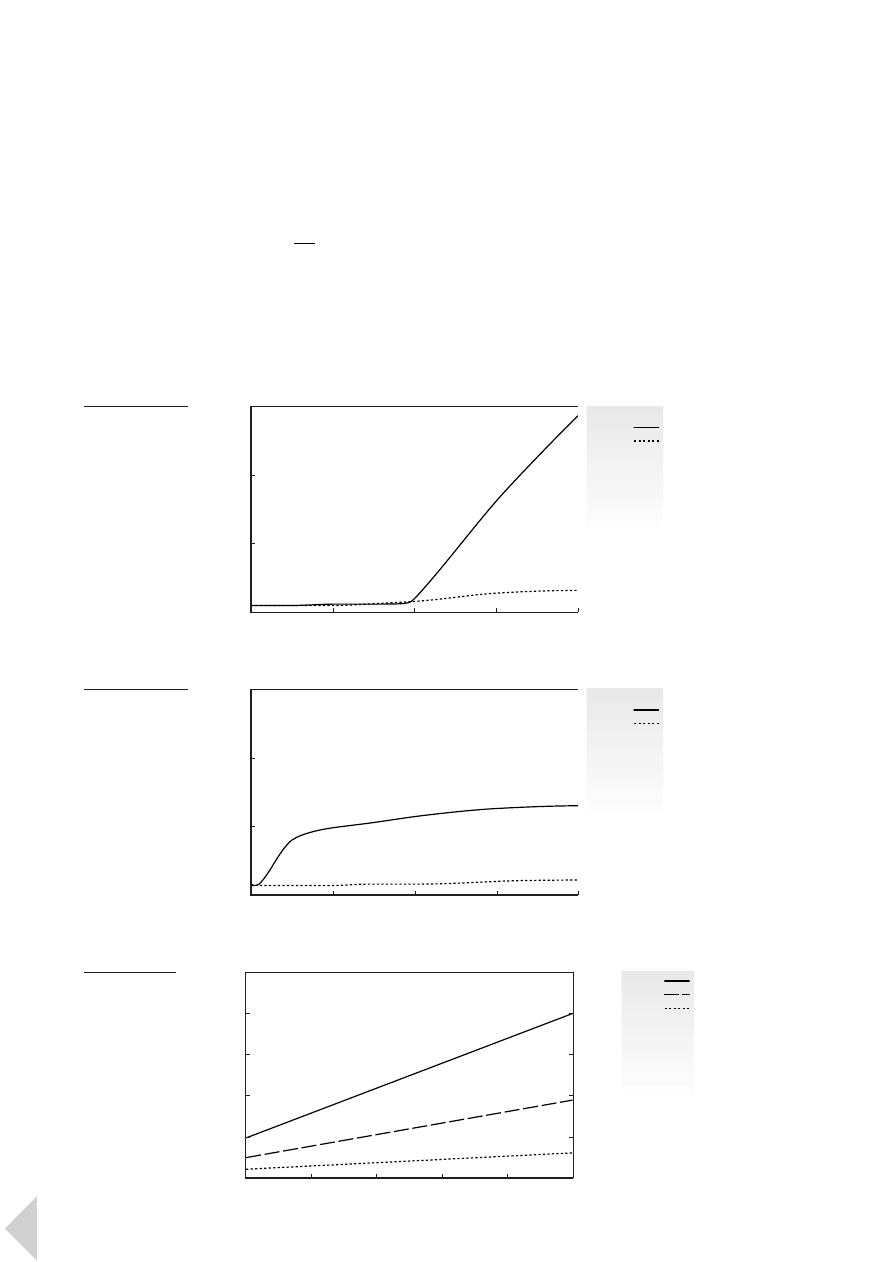
For applications which are exposed
to critical environments of intense
sunlight and high humidity, Lexan
resin can be additionally protected in
various ways. Tailor-made glass clear
UV cap-layers further improve the
weathering resistance of extruded
Lexan sheet, while for injection
moulded parts a variety of coatings,
including a range of GE Silicone
hardcoats, enhance weathering,
scratch and abrasion resistance.
■
F I G U R E S
2 6 and 2 7 illustrate the
enhanced resistance to haze and
yellowing which can be obtained
through the application of a silicone
hardcoat.
4.8
Processibility
To obtain extruded sheet, blow
moulded or injection moulded parts,
the material’s flow properties are
critical. These are measured based on
melt flow length and melt tempera-
ture. The flow lengths of GE Plastics
materials are given as calculated disk
flow lengths, where the injection
pressure is plotted against the radial
flow length. Determination of the
calculated disk flow length is
important when trying to predict
whether or not a part can be filled.
As an example,
■
F I G U R E
2 8 shows
the calculated disk flow lengths of
Lexan 141R.
The melt flow length of a material is a
function of viscosity, shear properties
and thermal properties.
41
L e x a n P r o f i l e 4 P r o p e r t i e s a n d D e s i g n
■
F I G U R E
2 6
Haze of transparent
Lexan, coated and
uncoated, after
accelerated outdoor
exposure
Lexan
uncoated
coated
Lexan
uncoated
coated
Haze (%)
Exposure (hours)
15
10
5
0
0
500
1000
1500
2000
■
F I G U R E
2 7
Yellowness Index
of transparent
Lexan, coated and
uncoated, after
accelerated outdoor
exposure
Y
ellowness index
Exposure (hours)
15
10
5
0
0
500
1000
1500
2000
■
F I G U R E
2 8
Calculated flow
length indication
of Lexan 141R
3 mm
2 mm
1 mm
Flow length (mm)
Injection time (s)
Gate pressure (MPa)
500
400
300
200
100
0
5
4
3
2
1
0
20
40
60
80
100
120
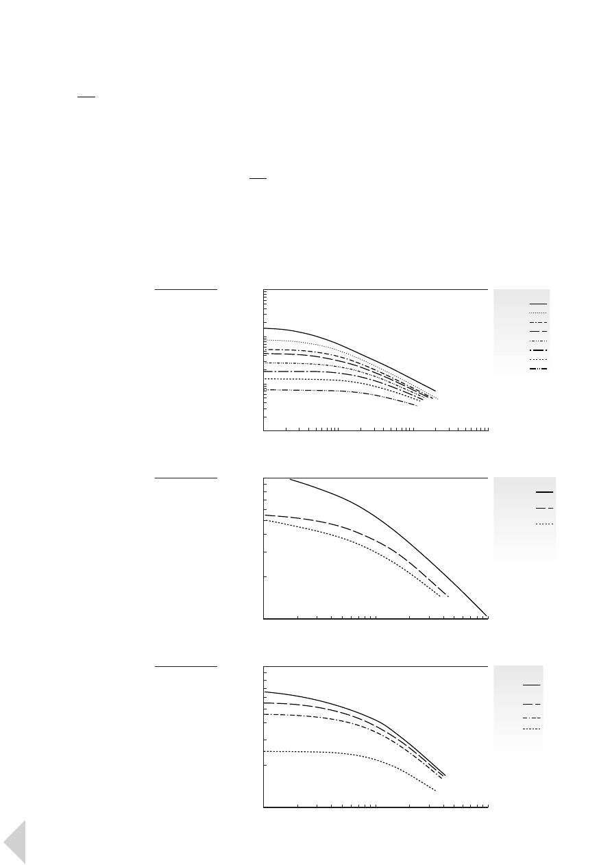
4.8.1
Viscosity
Lexan resin is available in a wide
range of viscosities which are
obtained by producing polycarbonate
with different molecular weights:
higher molecular weight grades
have a higher viscosity.
The portfolio ranges from ultra-low
viscosity Lexan OQ grades for the
DVD format, to very high viscosity
grades for multiple wall extrusion, as
depicted in
■
F I G U R E
2 9 .
■
F I G U R E
3 0
shows the range of melt viscosities for
various glass-filled grades, while
■
F I G U R E
3 1 relates specifically to
selected flame-retarded grades.
Common viscosity tests include melt
viscosity, MV, and melt volume rate,
MVR, measurements.
4.8.2
Shear properties
MV tests are carried out over a large
range of shear rates. As materials
show significantly different MV
curves, comparisons should be made
according to the MV curves rather
than on the MVR. As can be seen in
■
F I G U R E
3 2 , Lexan resin exhibits
a very low degree of shear thinning
when compared with other
thermoplastics. Unlike most
thermoplastic materials,
polycarbonate shows an almost
Newtonian behaviour, which means
that the viscosity is hardly influenced
by the shear rate.
Shear curves showing the relationship
between shear rate and viscosity at
different temperatures are required
for accurate injection moulding
simulation.
42
L e x a n P r o f i l e 4 P r o p e r t i e s a n d D e s i g n
■
F I G U R E
2 9
Capillary melt
viscosity of Lexan
showing a wide
range of available
viscosities
(300°C)
Lexan
ML3021A
201R
261R
241R
221R
HF1110R
ML3729
OQ1020LN
Viscosity (Pa
·sec)
Shear rate (sec
-1
)
10
4
10
3
10
2
10
1
10
2
10
3
10
4
10
5
■
F I G U R E
3 1
Capillary melt
viscosity of
standard flame
retarded Lexan
grades (300°C)
Lexan
950
950A
940
940A
920
920A
Viscosity (Pa
·sec)
Shear rate (sec
-1
)
10
3
10
2
10
2
10
3
10
4
■
F I G U R E
3 0
Capillary melt
viscosity of
standard glass
filled Lexan
(300°C)
Lexan
3414R
40% glass filled
500R
10% glass filled
3412R
20% glass filled
Viscosity (Pa
·sec)
Shear rate (sec
-1
)
10
3
10
2
10
2
10
3
10
4
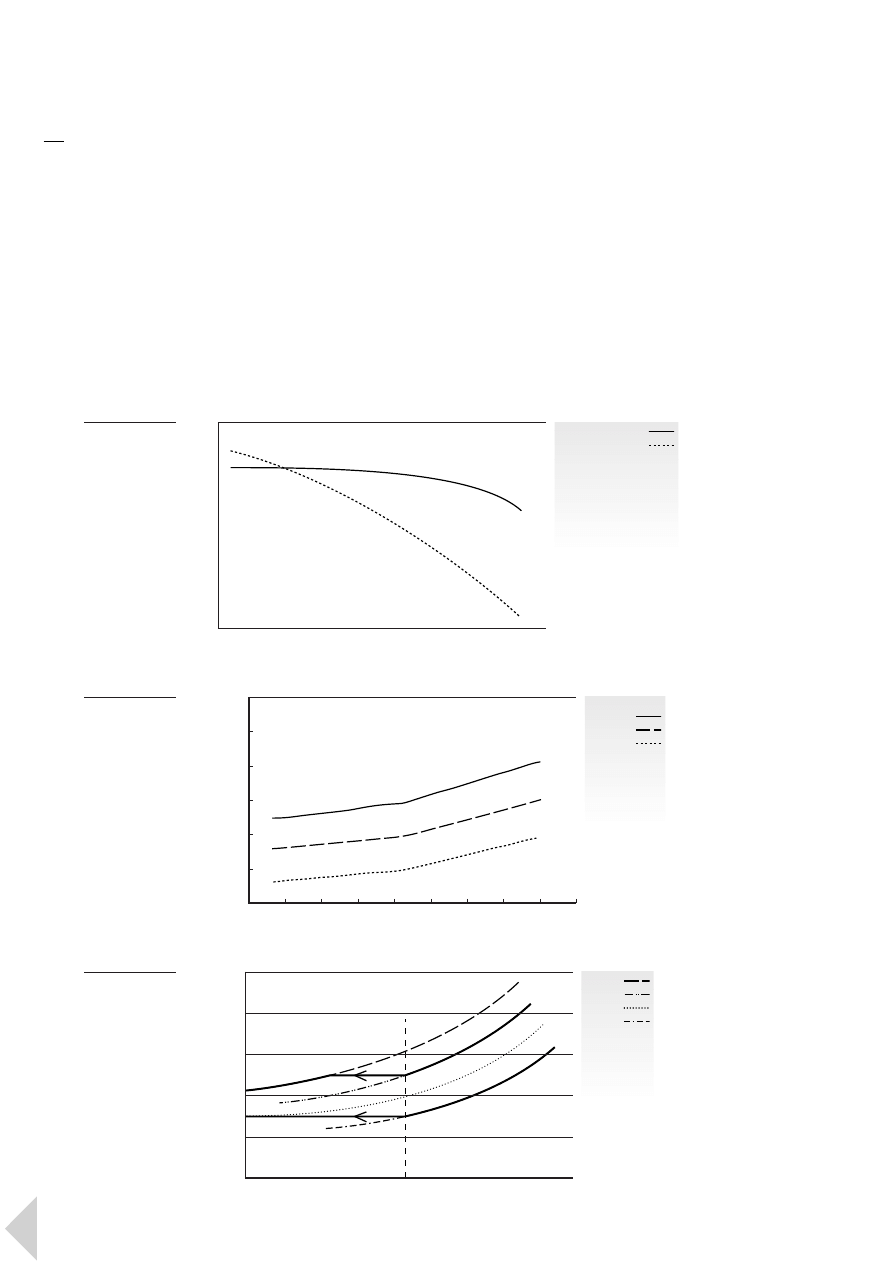
4.9
Mould shrinkage
Mould shrinkage refers to the
shrinkage that a moulded part
undergoes when it is removed
from a mould and cooled at room
temperature. Expressed as an average
percentage, mould shrinkage can
vary considerably depending on the
mould geometry, the processing
conditions and the type of resin.
As an amorphous material, Lexan
resin exhibits lower shrinkage than
semi-crystalline materials. The levels
of shrinkage in both cross-flow and
flow direction are also closer to each
other for amorphous materials, which
makes it easier to produce precise
parts. The addition of glass
reinforcement increases the degree
of orientation but lowers shrinkage.
The influence of the material on
shrinkage is usually expressed by the
PVT (Pressure-Volume-Temperature)
relationship. This relationship is
illustrated for both unreinforced and
glass-fibre reinforced Lexan grades in
■
F I G U R E
3 3 .
The packing or holding pressure
phase in the injection moulding
process also has a significant effect on
shrinkage. In general, the higher the
holding pressure and the longer it is
effective, the smaller the shrinkage.
This is illustrated in
■
F I G U R E
3 4 .
43
L e x a n P r o f i l e 4 P r o p e r t i e s a n d D e s i g n
■
F I G U R E
3 3
PVT relationship
for unreinforced
and glass
reinforced Lexan
(80MPa)
Lexan
141
500
3412R
Specific volume (cm
3
/g
)
Temperature (°C)
1.00
0.95
0.90
0.85
0.80
0.75
0.70
0
40
80
120
160
200
240
280
320
360
■
F I G U R E
3 2
Melt viscosity
of polycarbonate
and most other
thermoplastics
Viscosity
Shear rate
polycarbonate
most thermoplastics
■
F I G U R E
3 4
Typical PVT
relationship
for Lexan PC.
Higher holding
pressure reduces
volumetric
shrinkage
0 MPa
50 MPa
100 MPa
150 MPa
Specific volume (m
3
/kg)
Temperature
V
50
V
150
T
room
T
freeze

Lexan polycarbonate can be
successfully processed by injection
moulding, structural foam moulding,
extrusion, injection (stretch) blow
moulding and extrusion blow
moulding. Extruded sheet from
Lexan polycarbonate resin can be
thermoformed. Standard equipment
can be used and the processing range
is very broad. Fast cycle times are
possible and any rejects can be
ground and reused, providing
contamination has not occurred
during processing.
5.1
Pre-drying
Most thermoplastic materials absorb
atmospheric moisture which, at
normal processing temperatures,
can cause polymer degradation.
This consequently lowers property
levels, in particular impact strength.
Lexan polycarbonate therefore must
be thoroughly dried before moulding
to ensure optimum part performance
and appearance. The recommended
drying temperature is 120°C; the time
required to achieve sufficient drying
is dependent on the type of dryer
and varies from 2 to 4 hours. Target
moisture content should be a
maximum of 0.02%. Excessive drying
times of over 24 hours will not affect
the properties of the polymer but
they might decrease release
performance during processing.
5.2
Equipment
·
High compression ratio screws
or those with a short compression
zone should not be used.
It is recommended to use a
conventional 3-zone screw with a
L:D ratio of 20:1 - 25:1 and a
compression ratio of 2:1 - 2.5:1.
·
Conventional construction materials
for screw and barrel are acceptable
for the processing of Lexan resin.
However, screws and cylinders of a
bimetallic type with high abrasion
and corrosion resistance are
preferred, especially for glass-filled
grades.
·
A vented barrel and screw is not a
satisfactory alternative to pre-drying
and is therefore not recommended
for Lexan resin. If a vented barrel is
used, then the level of moisture which
is present in the material, and the
percentage of the shot capacity,
will have a considerable influence
on whether any degradation is
encountered as a result of hydrolysis.
·
A free-flowing nozzle with its own
heater band and control is
recommended. Nozzle openings
have to be as large as possible.
·
It is possible to mould with as little as
35 N/mm
2
clamping force but more
commonly pressures are between
40 and 50 N/mm
2
. For complex thin
wall components requiring fast
injection speeds combined with high
injection pressures, a clamping force
of up to 80 N/mm
2
is required.
Careful attention to the right tool/
equipment combination is critical for
complex thin wall components which
require fast processing and high
injection pressures.
5.3
Processing conditions
Melt temperature
It is important not to create long
residence times which can result
in material degradation. For Lexan
resin, the ideal maximum residence
time is between 6 and 12 minutes,
depending on the selected melt
temperature. When processing
Lexan on the upper limit of the
melt temperature range, it is
recommended that the shot size
is 60% - 80% of the barrel capacity
to minimize residence time.
Back pressure
A machine back pressure of 5 - 10 bar
is recommended in order to improve
melt quality and maintain a consistent
shot size. For glass-reinforced grades,
careful monitoring of back pressure is
advisable in order to minimize fibre
damage.
Screw rotation speed
Screw surface speeds should not
exceed 250 - 300 mm/s.
For reinforced grades a screw
speedat the lower end of the range
is recommended.
Suck back
The suck back stroke should be just
enough to keep the resin in and the
air out, to avoid melt degradation
and subsequent moulding problems.
Screw cushion
A screw cushion of 3 - 10 mm is
recommended, depending on the
screw diameter. Without a cushion it
is not possible for the after pressure
to have an effect.
Injection speed
The fastest possible injection speed is
desirable due to Lexan resin’s fast set-
up times, especially when using glass-
reinforced grades. Adequate venting
is essential when selecting a fast
injection speed.
Mould temperature
Lexan resin should always be
moulded in temperature-controlled
moulds. High mould temperatures
are desirable for optimum flow,
minimum moulded-in stress and
optimal surface appearance.
5.4
Venting
Good mould venting is essential to
prevent blistering or burning and
to aid cavity filling. Ideally the vents
should be located at the end of the
material flow paths. Inadequate or
poorly located venting can result in
44
5
P r o c e s s i n g
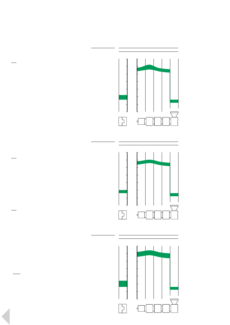
incomplete filling, poor weld line
strength, uneven shrinkage, warping
and the need for excessive injection
pressure to fill the cavity.
5.5
Interruption of production
Keeping Lexan resin in the cylinder
overnight or over a weekend is
generally not recommended. If
production delays are unavoidable,
the following precautions are
recommended.
·
Reduce cylinder temperature to
170°C - 180°C
·
Leave heaters on
·
Ensure that the temperature never
drops below 160°C. This is to prevent
the resin from adhering to the
cylinder walls which may pull off
metal particles and degraded resin
as it cools and contracts, causing
black specks in the mouldings when
production is restarted
·
During production delays, empty the
screw to prevent overheating
5.6
Purging of the barrel
Thorough purging of the barrel is
required when changing materials.
The best purging material for Lexan
resin is PMMA. PA or ABS should not
be used as a purging material directly
after Lexan resin. The cylinder
temperature should be lowered if the
resins to be moulded afterwards are
POM, ABS or PA.
5.7
Recycling
Sprues and faulty mouldings can all
be reground with minimal reduction
in resin properties. Care must be
taken to ensure that the regrind is
free from impurities and that proper
pre-drying of the regrind has been
carried out. Blends of regrind and
virgin material are possible in the
ratio of 20:80. Regrind should not
®be used in applications where
impact performance and/or agency
compliance are required.
Note
Further information on the
processing of engineering
thermoplastics can be found
in GE Plastics brochures:
·
Injection Moulding Mini Guide
·
Engineering Thermoplastics in
the Extrusion Industry
45
L e x a n P r o f i l e 5 P r o c e s s i n g
Nozzle
Zone 3
Zone 2
Zone 1 Hopper
Mould
Melt temperature 280 - 310 °C
°C
350
300
250
200
150
100
50
0
■
F I G U R E
3 5
Typical moulding
temperatures
for Lexan general
purpose: 141R
Nozzle
Zone 3
Zone 2
Zone 1 Hopper
Mould
Melt temperature 280 - 300 °C
°C
350
300
250
200
150
100
50
0
■
F I G U R E
3 6
Typical moulding
temperatures
for Lexan flame
retarded: 940
Nozzle
Zone 3
Zone 2
Zone 1 Hopper
Mould
Melt temperature 290 - 320 °C
°C
350
300
250
200
150
100
50
0
■
F I G U R E
3 7
Typical moulding
temperatures
for Lexan flame
retarded, glass
filled: 500R

Although most Lexan parts are
moulded as finished components,
the design and ultimate use of
certain parts may require machining,
assembly or finishing operations.
Lexan resin makes a wide variety of
secondary operations available to the
design engineer.
6.1
Welding
Welding is a commonly used
permanent assembly technique for
engineering thermoplastics. Lexan
parts can be welded using different
processes. Selecting the right process
depends on the size, shape and
function of the part:
·
Hot Plate welding
allows excellent
weld strengths to be achieved at
temperatures of 260°C - 300°C
·
Friction welding
can be applied,
using either the vibration, orbital
or rotation method
·
Ultrasonic welding
is commonly
used, in particular for mobile
telephone components. Welding
amplitudes with 20 kHz ultrasonic
processes should be in the range
of 25 - 40 µm (0-peak)
·
Induction Welding
6.2
Adhesives
Lexan resin parts can be bonded to
other plastics, glass, aluminium, brass,
steel, wood and other materials.
A wide variety of adhesives can be
used, sometimes with the addition of
a suitable primer. In general, Lexan
parts can be easily solvent bonded to
parts made from Lexan, Cycolac
®
ABS
or Cycoloy
®
PC/ABS alloy with Methyl
Ethyl Ketone (MEK) or in mixtures
of MEK with Cyclohexanone, ideally
50:50.
Cleaning parts
Thorough cleaning of Lexan parts
before bonding is essential in order
to avoid part failure. All oil, grease,
paint, mould releases, rust oxides,
etc., must be removed by washing
with solvents which are compatible
with Lexan resin. These solvents
include isopropyl alcohol, heptane
or a light solution of non-alkaline
detergents. Bond strength is further
improved by sanding, sand blasting or
vapour blasting the bonding surfaces.
6.3
Mechanical assembly
Mechanical assembly techniques are
widely used with Lexan parts. To
achieve optimum results, mechanical
fasteners should be kept free from oil
and grease. Depending on the type of
fastener, a permanent stress or
deformation is applied locally. Clamp
forces should be controlled or
distributed over a large surface area.
This is in order to decrease local
stresses in the part after assembly and
to minimize the risk of loosening the
fasteners through creep and
relaxation. Notches in the design as
well as notches resulting from
mechanical fasteners should also be
avoided.
Recommended assembly techniques:
·
Thread-forming screws rather
than thread cutting screws are
recommended. Screws with a
maximum flank angle of 30° are
preferred for minimal radial stresses
·
Inserts which leave low residual
stresses can be used. Installation by
heat or ultrasound are the preferred
techniques. Press and expansion
inserts produce high hoop stresses in
bosses and should therefore be used
with caution
·
Snap fit assembly
·
Rivets
·
Staking
Note
General information on Secondary
Operations like welding, mechanical
assembly and bonding of engineering
thermoplastics can be found in the
following GE Plastics brochures:
·
Assembly Guide
·
Design Guide
46
6
S e c o n d a r y O p e r a t i o n s
Epoxy
PUR
PUR
PUR hot
MS
Silicone
Silicone
Acrylic
Cyano-
2K
1K
2K
melt reactive
polymer
1K
2K
2K
acrylate
primer
no
yes
no
no
no
yes/no
no
no
no
aggressive
at high t°
no
no
no
no
alkoxy
no
yes
yes
■
TA B L E
6
Compatibility of adhesives with Lexan resin

6.4
Painting
A wide variety of colours and textures
can be applied to Lexan using
commercially available organic paints
and conventional application
processes. Painting is an economical
means of enhancing aesthetics and
providing colour uniformity.
Pre-treatment
·
Handwashing the part with cleaning
agents based on alcohol or aliphatic
hydrocarbons
or:
·
Powerwashing the part with cleaning
agents based on detergents dissolved
in water. These detergents can be
either acidic by nature, (pH 3 - 4),
or neutral, (pH 8 - 9). Alkaline-based
detergents (pH >11) should be
avoided.
Paint selection
Paint selection is determined by the
desired decorative effect, specific
functional needs and the application
technique to be applied. A variety of
conventional and waterborne paints
can be successfully applied to Lexan
resin. Generic types include:
·
Acrylic
·
Epoxy
·
Polyester
·
Polysiloxane
·
Polyurethane
Special coatings
·
A range of siloxane-based coatings
with inherent glass-like optical
properties has been developed to
provide Lexan resin transparent parts
with optimum chemical and scratch
resistance and UV protection. These
special coatings can be easily applied
by dip coating, flow coating or by
spraying
·
Acrylic-based coatings can be used in
applications such as compact discs
where only UV protection and
moderate scratch resistance is
required
·
Coatings can be used to help
minimize colour degradation
·
Conductive coatings offer shielding
against radio frequency interference
(RFI) or electromagnetic
interference (EMI)
Paint solvents
It is important that solvent
formulations are carefully considered
when selecting a paint for use with
amorphous resins such as Lexan.
It should be stressed that it can be
difficult to achieve an ideal match
between solvent and substrate.
Although it is generally difficult
to give rules for balancing solvent
mixtures, there are some basic
guidelines. For example, strong
solvent action can be balanced with
a non-dissolving liquid like butanol
or dipentene. Solvents with strong
embrittlement effects, on the other
hand, can be balanced by adding
stronger dissolving solvents. It should
be noted that lower boiling point
solvents cause embrittlement effects
more quickly.
The occurrence of stress cracking is
a result of solvent action on the one
hand and stresses in the part on the
other. The level of stress in the part
should be ideally below 5 MPa.
This is achieved through optimal part
and tool design and proper moulding
procedures. In general, if stress levels
are above 10 MPa, painting will
become critical. In case of doubt,
Lexan resin parts should be tested
using a mixture of Toluene and
n-Propanol or propylene-carbonate.
6.5
Metallisation
Properties usually associated with
metals such as reflectivity, abrasion
resistance, electrical conductivity
and decorative surfaces can be
added to plastics through
metallisation. Three of the more
commonly applied metallisation
techniques are discussed here.
Vacuum metallisation
Vacuum metallisation through
Physical Vapour Deposition involves
the depositing of an evaporated
metal, mostly aluminium, on a
substrate. To achieve evaporation,
the pure metal is heated in a deep
vacuum. To ensure a good result
when using this method with Lexan
resin, a glow discharge pre-treatment
is highly recommended.
After vacuum metallisation, the
aluminium must be protected
against environmental influences.
This is because of the ultra-thin
layer thickness combined with the
reactive nature of aluminium to
humidity. Most commonly this
protection is provided through the
application of a Plasil/Glipoxan top
layer, (a silicone-based monomer
layer which is applied in the vacuum),
or a clear coat top layer.
In general, unreinforced Lexan
resin does not require a basecoat
or lacquer primer layer before
metallisation because of the good
surface quality of Lexan parts after
moulding. However, in certain cases,
application of a basecoat is
recommended to enhance reflectivity,
in particular where a glass-filled
Lexan material has been specified.
47
L e x a n P r o f i l e 6 S e c o n d a r y O p e r a t i o n s

In most cases a surface activation
pre-treatment is required.
·
Glow discharge takes place in a
vacuum vessel in the presence of a low
pressure gas such as air. This method
gives an increased surface energy and
micro porosity to the Lexan part.
·
Cleaning with a cloth or solvents is
not recommended because of the
sensitivity to scratches that can be
seen after metallisation. The best
method is to keep the mouldings
clean and to metallise the parts as
soon as possible after moulding, or
to store them in clean containers.
Plating
This can be done by two methods.
In the first, electro plating, current
is used to effect an electrolytic
deposition of metals derived from a
dissolved metal salt. Most frequently
used metals include chrome, nickel
or gold.
The second method, electroless
plating, is executed without the
addition of current to the galvanic
process. Electroless plating can be
further divided into non-selective
(double-sided) and selective (single-
sided) plating.
·
For non-selective or all-over
electroless plating, a pre-etch is
generally required with Lexan resin.
·
Selective electroless plating starts with
the masking of those areas of the part
which must remain metal-free.
A catalytic lacquer is then applied to
seed the exposed surface to initiate
the deposition of metal after
immersion in the metal salt solution.
·
If only EMI shielding is required, an
electroless copper layer of 1 - 2 µm is
applied with a finish of electroless
nickel.
Hot foil stamping
In this dry metallisation technique,
the metal foil is impressed on the
plastic surface with a heated die or
rubber roll. Standard foils are
available for use with Lexan resin
parts, but it is recommended to test
each grade and new application for
compatibility and melting point.
6.6
Laser marking
The laser marking of thermoplastics
is a complex process. The differing
demands of applications, together
with a diverse range of materials,
pigments and additives, as well as
the equipment itself, provide a large
number of variables. Through its
advanced research and development
programme, GE Plastics has gained
valuable insight into the thermal,
optical, mechanical and chemical
processes which take place during
laser marking. An important result of
this has been the development of a
broad tailor-made range of materials
using proprietary combinations of
pigments and additives. These
include Lexan grades 121R, 141R
and ML3432 which provide light on
dark contrast laser marking.
Note
General information on Secondary
Operations like painting and
metallisation of engineering
thermoplastics can be found in the
following GE Plastics brochures:
·
Painting Guide
·
Metallization Guide
48
L e x a n P r o f i l e 6 S e c o n d a r y O p e r a t i o n s

GE Plastics
0
50
100
150
200°C
15000 MPa
12500
10000
7500
5000
2500
0
Lexan
Heat
Flammability
•
nt
HB
V2
V1
V0
5VB
5V
A
0
40
80
120
160
200 MPa
100 kJ/m
2
80
60
40
20
0
Modulus
Impact
Str
ength
profile
Lexan
®

25
300°C
GE Plastics in Europe
European Headquarters
General Electric Plastics B.V.
1 Plasticslaan, PO Box 117
NL - 4600 AC Bergen op Zoom
The Netherlands
Tel. (31) (164) 29 29 11
Fax (31) (164) 29 29 40
Headquarters Sales Region
General Electric Plastics B.V.
Gagelboslaan 4
NL - 4623 AD Bergen op Zoom
The Netherlands
Tel. (31) (164) 29 23 91
Fax (31) (164) 29 17 25
Benelux Sales Region
General Electric Plastics B.V.
Gagelboslaan 4
NL - 4623 AD Bergen op Zoom
The Netherlands
Tel. (31) (164) 29 11 92
Fax (31) (164) 29 17 25
United Kingdom
GE Plastics Limited
Old Hall Road
Sale
Cheshire M33 2HG United Kingdom
Tel. (44) (161) 905 50 00
Fax (44) (161) 905 51 19
Germany
General Electric Plastics GmbH
Eisenstraße 5
D - 65428 Rüsselsheim Germany
Tel. (49) (6142) 6010
Fax (49) (6142) 65746
France
General Electric Plastics France S.à.R.L.
Z.I. St. Guénault B.P. 67
F - 91002 Evry-Cedex France
Tel. (33) (1) 60 79 69 00
Fax (33) (1) 60 77 56 53
Italy
General Electric Plastics Italia S.p.A.
Viale Brianza, 181
I - 20092 Cinisello Balsamo (Milano) Italy
Tel. (39) (02) 61 83 41
Fax (39) (02) 61 83 42 11
Russia
General Electric International A/O
Kosmodamianskaia Nab, 52
Building 1
113054 Moscow Russia
Tel. (7) (095) 935 7312
Fax (7) (095) 935 7317
Spain
General Electric Plastics Ibérica S.A
Avenida Diagonal, 652-656
Edificio D. Planta 3
08034 Barcelona Spain
Tel. (34) (93) 252 16 00
Fax (34) (93) 280 26 19
Sweden
GE Plastics Limited
Box 1242, Skeppsbron 44
S-11182 Stockholm Sweden
Tel. (46) (8) 402 40 24
Fax (46) (8) 723 12 92
Turkey
GE Plastics Turkey
Is Bankasi Bloklari
Cemil Topuzlu Caddesi
A Blok, Daire 18
81030 Feneryolu
Istanbul Turkey
Tel. (90) (216) 386 7104
Fax (90) (216) 386 5812
GE Plastics in India
GE Plastics India Ltd.
405-B, Sector 20
Udyog Vihar Phase - III
Gurgaon, Haryana - 122 016, India
Tel. (91) 124 341 801 to 806
Fax (91) 124 341 817 or 815
GE Plastics in South Africa
GE Plastics South Africa
General Electric South Africa (Pty) Ltd.
15th floor Sandton Office Tower
Sandton 2146
Johannesburg, South Africa
Tel. (27) 11 784 2108
Fax (27) 11 784 2216
GE Plastics in the Americas
Worldwide Headquarters
United States
GE Plastics
1 Plastics Avenue
Pittsfield, MA 01201
USA
Tel. (1) (413) 448 7110
Fax (1) (413) 448 7493
Canada
GE Plastics Canada Ltd.
2300 Meadowvale Boulevard
Mississauga, Ontario L5N 5P9
Canada
Tel. (1) (905) 858 5774
Fax (1) (905) 858 5798
Mexico
GE Plastics - Mexico S.A. de C.V.
Av. Prolongacion Reforma #490, 4o. piso
Colonia Santa Fe
01207 Mexico, D.F.
Tel. (11) 525 257 6060
Fax (11) 525 257 6070
Brazil
GE Plastics South America S.A.
Av. Nações Unidas, 12995 - 20° andar -
Cep 04578.000
São Paulo - SP
Brazil
Tel. (55) 11 5505 2800
Fax (55) 11 5505 1757
GE Plastics in the Pacific
Pacific Headquarters
GE Plastics Pacific Pte. Ltd.
240 Tanjong Pagar Road
GE Tower #09-00
Singapore 0208
Tel. (65) 326 3301
Fax (65) 326 3303/(65) 326 3290
Australia
GE Plastics Australia
175 Hammond Road
Dandenong, Victoria 3175
Australia
Tel. (61) 3 794 4201
Fax (61) 3 794 8563
China
GE Plastics China
Beijing, 3rd floor
CITIC Bldg. No.19
Jian Guo Men Wai Avenue
Beijing 100004
China
Tel. (86) (21) 270 6789
Fax (86) (1) 512 7345
Hong Kong
GE Plastics Hong Kong Ltd.
Room 1088 - Tower 1
The Gateway, Tshimshatsui
Kowloon
Hong Kong
Tel. (852) 2629 0827
Fax (852) 2629 0800
Japan
GE Plastics Japan Ltd.
Nihombashi Hamacho Park Building
2-35-4, Nihombashi-Hamacho
Chuo-ku, Tokyo 103
Japan
Tel. (81) 3 5695 4888
Fax (81) 3 5695 4859
Korea
GE Plastics Korea Co. Ltd.
231-8 Nonhyun-Dong
Kangnam-Ku
Seoul 135-010
Republic of Korea
Tel. (82) 2 510 6250/1
Fax (82) 2 510 66 66/7
Singapore
GE Plastics Singapore Pte Ltd.
c/o 23 Benoi Road
Singapore 2262
Tel. 65 846 3290
Fax 65 861 3063
Taiwan
GE Plastics Taiwan
9/F 37 Min Chuan East Road Sec 3
Taipei 10462
Taiwan, Rep. of China
Tel. (886) 2 509 2124/6
Fax (886) 2 509 1625
Thailand
GE Plastics Thailand
21st Floor
Thaniya Plaza Building
52 Silom Road
Bangkok 10500
Thailand
Tel. (66) (2) 231 2323
Fax (66) (2) 231 2322
DISCLAIMER: THE MATERIALS AND PRODUCTS OF THE BUSINESSES
MAKING UP THE GE PLASTICS UNIT OF GENERAL ELECTRIC COMPANY*,
USA, ITS SUBSIDIARIES AND AFFILIATES (“GEP”), ARE SOLD SUBJECT TO
GEP’S STANDARD CONDITIONS OF SALE, WHICH ARE INCLUDED IN THE
APPLICABLE DISTRIBUTOR OR OTHER SALES AGREEMENT, PRINTED ON
THE BACK OF ORDER ACKNOWLEDGMENTS AND INVOICES, AND AVAILABLE
UPON REQUEST. ALTHOUGH ANY INFORMATION, RECOMMENDATIONS,
OR ADVICE CONTAINED HEREIN IS GIVEN IN GOOD FAITH, GEP MAKES NO
WARRANTY OR GUARANTEE, EXPRESS OR IMPLIED, (I) THAT THE RESULTS
DESCRIBED HEREIN WILL BE OBTAINED UNDER END-USE CONDITIONS, OR
(II) AS TO THE EFFECTIVENESS OR SAFETY OF ANY DESIGN INCORPORATING
GEP MATERIALS, PRODUCTS, RECOMMENDATIONS OR ADVICE. EXCEPT
AS PROVIDED IN GEP’S STANDARD CONDITIONS OF SALE, GEP AND ITS
REPRESENTATIVES SHALL IN NO EVENT BE RESPONSIBLE FOR ANY LOSS
RESULTING FROM ANY USE OF ITS MATERIALS OR PRODUCTS DESCRIBED
HEREIN. Each user bears full responsibility for making its own determination as to
the suitability of GEP’s materials, products, recommendations, or advice for its own
particular use. Each user must identify and perform all tests and analyses necessary to
assure that its finished parts incorporating GEP materials or products will be safe and
suitable for use under end-use conditions. Nothing in this or any other document, nor
any oral recommendation or advice, shall be deemed to alter, vary, supersede, or waive
any provision of GEP’s Standard Conditions of Sale or this Disclaimer, unless any such
modification is specifically agreed to in a writing signed by GEP. No statement contained
herein concerning a possible or suggested use of any material, product or design is
intended, or should be construed, to grant any license under any patent or other
intellectual property right of General Electric Company or any of its subsidiaries or
affiliates covering such use or design, or as a recommendation for the use of such
material, product or design in the infringement of any patent or other intellectual
property right.
* Company not connected with the English company of a similar name.
Lexan
®
, Noryl
®
, Noryl
®
GTX
®
, Noryl
®
Xtra, Valox
®
, Ultem
®
, Xenoy
®
, Cycolac
®
, Cycoloy
®
and Enduran
®
are Registered Trademarks of General Electric Co., USA.
Gelon
™
is a Trademark of General Electric Co., USA.
Lexan Eng/4M/0998
!
For your convenience, the preference
for ÔMax ÒFit VisibleÓ MagnificationÕ
should be changed from 800% to 150%.
Wyszukiwarka
Podobne podstrony:
General Electric
Prezentacja i analiza etycznej polityki GENERAL ELECTRIC
General Electric
electronic resource guide pl
Home Power Magazine Before Generating Electricity, Calculate The Load You Will Need (Analysi
General Engine Tuning Guide
7044 General Electric
8950 General Electric
6189 General Electric
Biomass Fired Superheater for more Efficient Electr Generation From WasteIncinerationPlants025bm 422
Fading Suns Guide to Character Generation
laborki - S2, 04. 01. ELECTRICAL, 07. Elektryka publikacje, 08. Generators, #Synchronizing
High voltage electrostatic generator
Alternator Secrets Electrical Generator Power
Electrician's Troubleshooting and Testing Pocket Guide
Biomass Fired Superheater for more Efficient Electr Generation From WasteIncinerationPlants025bm 422
US Patent 447,921 Alternating Electric Current Generator
US Patent 511,916 Electric Generator
więcej podobnych podstron