

Electrician’s
Troubleshooting
and Testing
Pocket Guide

ABOUT THE AUTHORS
H. Brooke Stauffer is Executive Director of Standards
and Safety for the National Electrical Contractors
Association (NECA) in Bethesda, Maryland. He is
responsible for developing and publishing the
National Electrical Installation Standards (NEIS), a
series of ANSI-approved best practices for electrical
construction and maintenance work. He also has
written a number of electrical books, including
Residential Wiring for the Trades (McGraw-Hill, 2006).
Mr. Stauffer has been a member of three different
National Electrical Code-Making Panels (CMPs).
John E. Traister (deceased) was involved in the elec-
trical construction industry for more than 35 years.
He authored or co-authored numerous McGraw-Hill
books for electrical professionals, including Illustrated
Dictionary for Electrical Workers, Electrician’s Exam
Preparation Guide, and Handbook of Electrical Design
Details.
Copyright © 2007, 2000, 1996 by The McGraw-Hill Companies, Inc.
Click here for terms of use.

Electrician’s
Troubleshooting
and Testing
Pocket Guide
Third Edition
H. Brooke Stauffer
John E. Traister
McGraw-Hill
New York
Chicago
San Francisco
Lisbon
London
Madrid
Mexico City
Milan
New Delhi
San Juan
Seoul
Singapore
Sydney
Toronto

Copyright © 2007, 2000, 1996 by The McGraw-Hill Companies, Inc. All rights reserved.
Manufactured in the United States of America. Except as permitted under the United
States Copyright Act of 1976, no part of this publication may be reproduced or distrib-
uted in any form or by any means, or stored in a database or retrieval system, without the
prior written permission of the publisher.
0-07-150929-1
The material in this eBook also appears in the print version of this title: 0-07-148782-4.
All trademarks are trademarks of their respective owners. Rather than put a trademark
symbol after every occurrence of a trademarked name, we use names in an editorial fash-
ion only, and to the benefit of the trademark owner, with no intention of infringement of
the trademark. Where such designations appear in this book, they have been printed with
initial caps.
McGraw-Hill eBooks are available at special quantity discounts to use as premiums and
sales promotions, or for use in corporate training programs. For more information, please
contact George Hoare, Special Sales, at george_hoare@mcgraw-hill.com or (212)
904-4069.
TERMS OF USE
This is a copyrighted work and The McGraw-Hill Companies, Inc. (“McGraw-Hill”) and
its licensors reserve all rights in and to the work. Use of this work is subject to these
terms. Except as permitted under the Copyright Act of 1976 and the right to store and
retrieve one copy of the work, you may not decompile, disassemble, reverse engineer,
reproduce, modify, create derivative works based upon, transmit, distribute, disseminate,
sell, publish or sublicense the work or any part of it without McGraw-Hill’s prior consent.
You may use the work for your own noncommercial and personal use; any other use of
the work is strictly prohibited. Your right to use the work may be terminated if you fail to
comply with these terms.
THE WORK IS PROVIDED “AS IS.” McGRAW-HILL AND ITS LICENSORS MAKE
NO GUARANTEES OR WARRANTIES AS TO THE ACCURACY, ADEQUACY OR
COMPLETENESS OF OR RESULTS TO BE OBTAINED FROM USING THE WORK,
INCLUDING ANY INFORMATION THAT CAN BE ACCESSED THROUGH THE
WORK VIA HYPERLINK OR OTHERWISE, AND EXPRESSLY DISCLAIM ANY
WARRANTY, EXPRESS OR IMPLIED, INCLUDING BUT NOT LIMITED TO
IMPLIED WARRANTIES OF MERCHANTABILITY OR FITNESS FOR A PARTIC-
ULAR PURPOSE. McGraw-Hill and its licensors do not warrant or guarantee that the
functions contained in the work will meet your requirements or that its operation will be
uninterrupted or error free. Neither McGraw-Hill nor its licensors shall be liable to you
or anyone else for any inaccuracy, error or omission, regardless of cause, in the work or
for any damages resulting therefrom. McGraw-Hill has no responsibility for the content
of any information accessed through the work. Under no circumstances shall
McGraw-Hill and/or its licensors be liable for any indirect, incidental, special, punitive,
consequential or similar damages that result from the use of or inability to use the work,
even if any of them has been advised of the possibility of such damages. This limitation
of liability shall apply to any claim or cause whatsoever whether such claim or cause
arises in contract, tort or otherwise.
DOI: 10.1036/0071487824

v
CONTENTS
Introduction
vii
1 Analog Test Instruments
1
2 Digital Multimeters
25
3 Troubleshooting Basics
39
4 Troubleshooting Dry-Type
Transformers
49
5 Troubleshooting Luminaires
(Lighting Fixtures)
57
6 Troubleshooting Electric
Motors
91
7 Troubleshooting Motor Bearings 159
8 Troubleshooting Relays and
Contactors
175
9 Troubleshooting Power Quality
Problems
191
10 Troubleshooting with Infrared
Thermography
209
Index 213
For more information about this title,
click here

This page intentionally left blank

E
lectrical measuring and testing instruments are used
in the installation, troubleshooting, and mainte-
nance of electrical systems of all types, particularly in
commercial and industrial facilities. Electricians and
technicians involved with installing, maintaining, and
repairing electrical equipment need a good working
knowledge of portable testing instruments and how
they are used to diagnose and fix problems in the field.
Most operational problems of electrical equipment
and systems involve one of four basic faults:
●
Short circuit
●
Ground fault
●
Open circuit
●
Change in electrical value
This guide describes troubleshooting techniques to
identify such problems using portable field-testing
instruments. Although it covers many types of test
equipment, this book emphasizes the use of digital
multimeters (DMMs), the most common and versatile
electrician’s diagnostic tool.
This new third edition of Electrician’s Troubleshooting
and Testing Pocket Guide includes updated information
vii
Copyright © 2007, 2000, 1996 by The McGraw-Hill Companies, Inc.
Click here for terms of use.

on testing and troubleshooting lighting systems,
expanded information on diagnosing power quality
problems, and a new chapter on thermographic diag-
nostic tools.
Scope of This Book
Electrician’s Troubleshooting and Testing Pocket Guide
covers the use of digital multimeters (DMMs) and
other testing equipment to troubleshoot electrical
and electronic circuits used for power and control
applications. In general, it concentrates on traditional
electromechanical and inductive equipment found in
commercial and industrial occupancies—motors,
transformers, lighting, and power distribution equip-
ment. In general, this guide does not cover testing
and troubleshooting of the following types of equip-
ment and systems:
Communications systems. The use of network
cable analyzers, optical time domain reflectometers
(OTDRs), optical power meters, and other equipment
used for testing and troubleshooting communica-
tions systems such as telecommunications, com-
puter local area networks (LANs), and outside plant
fiber-optic installations are outside the scope of this
publication.
Electronic components and systems. This book
touches on testing of electronic components such as
resistors, small capacitors, and diodes. However, the
broad subject of troubleshooting electronic compo-
nents and circuits using digital multimeters and other
viii

portable test equipment is covered in much greater
detail in a different McGraw-Hill publication:
Electronic Troubleshooting and Repair Handbook by
Homer L. Davidson (1995; ISBN 0-07-015676-X).
H. Brooke Stauffer
Executive Director of Standards and Safety
National Electrical Contractors Association (NECA)
Bethesda, Maryland
ix

This page intentionally left blank

Electrician’s
Troubleshooting
and Testing
Pocket Guide

This page intentionally left blank

We hope you enjoy this
McGraw-Hill eBook! If
you’d like more information about this book,
its author, or related books and websites,
please
click here.
Professional
Want to learn more?

T
raditional meters used by electricians and techni-
cians for field testing and troubleshooting are ana-
log type. In an analog meter, the magnitude of the
property being measured (such as voltage, current,
resistance, and illumination) is indicated by a corre-
sponding physical movement of a pointer, needle, or
other indicator. Voltage, for example, is shown by the
needle of a traditional voltmeter swinging to point at
a number on a dial.
Analog meters are generally limited to a single
function. The most common types are ammeters,
voltmeters, and resistance testers (frequently called
meggers in the field, after the name of one of the best-
known brands of resistance tester). In some cases the
usefulness of traditional analog electrical test instru-
ments can be extended or modified with special adap-
tors or sensors; some voltmeters, for example, can also
be used to measure temperature.
Today, the different types of single-function analog
meters have been largely replaced by digital (comput-
erized) meters that combine many measurement
functions within a single compact unit. These digital
multimeters (DMMs) are now used for most testing,
1
Copyright © 2007, 2000, 1996 by The McGraw-Hill Companies, Inc.
Click here for terms of use.
troubleshooting, and maintenance purposes. However,
there are still many older analog meters in use, and a
working knowledge of these diagnostic tools is useful
to electricians and technicians.
This chapter briefly describes the various types of
analog electrical meters and instruments, and how
they are used. Starting with Chapter 2, the rest of the
handbook concentrates primarily on using DMMs.
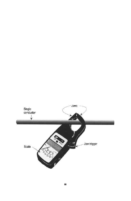
Ammeters
Figure 1-1 shows a clamp-on ammeter used to mea-
sure current in a conductor while the conductor is
energized. While exact operating procedures vary
with the manufacturer, most operate as follows when
measuring current:
2
1-1
Typical clamp-on-type ammeter.

Step 1. Release the pointer lock.
Step 2. Turn the selector knob until the highest
current range appears in the scale window.
Step 3. Press the trigger to open the jaws of the
clamp and place them around a single
conductor.
Step 4. Release finger pressure on the trigger
slowly, keeping an eye on the scale while
the jaws close around the conductor. If
the pointer jumps abruptly to the upper
range of the scale before the jaws are
completely closed, the current is too high
for the scale selected. Immediately remove
the jaws from around the conductor, and
use a higher scale.
Never encircle two or more conductors; only encir-
cle one conductor as shown in Figure 1-1. If the
pointer moves normally, close the jaws completely
and read the current in amperes indicated on the scale.
Accuracy
When using clamp-on ammeters, follow these precau-
tions to obtain accurate readings:
1. Be certain the frequency of the conductor
being tested is within the range of the instru-
ment. Most ammeters are calibrated at 70 Hz.
2. Magnetic fields can affect current readings.
To minimize this problem, try to avoid using
3

clamp-on ammeters close to transformers,
motors, relays, and contactors.
Ammeter Applications
Ammeters are useful for troubleshooting various elec-
trical components by indicating a change in electrical
value. Many examples and troubleshooting charts
found throughout this book. But here are two simple
examples of ammeter applications.
Three-phase motor
The approximate load on a three-phase motor can be
determined while the motor is running. To do this,
clamp the ammeter around each of the three-phase
conductors, one by one:
●
If the ammeter shows the motor is draw-
ing current close to its nameplate reading,
this indicates the motor is fully loaded.
●
If the ampere reading on each conductor
is significantly less, then the motor is not
carrying a full load.
●
If the current measured with the amme-
ter is higher than the nameplate, when
the motor is running at full speed and
rated voltage, then the motor can be
assumed to be overloaded.
Electric baseboard heater
The nameplate will indicate the heater’s characteristics.
Let’s assume that the nameplate indicates a 1000-W,
single-phase, two-wire heating element operating at
240 A. If an ammeter reading, which is taken while the
4
heater is operating, shows approximately 4 A of current,
this indicates the heater is working properly, because:
I ⫽
p
E
or
1000
240
⫽
4.16 A
But an ampere reading much different from 4 A
(either higher or lower) indicates some fault in either
the heater or the branch circuit supplying it.
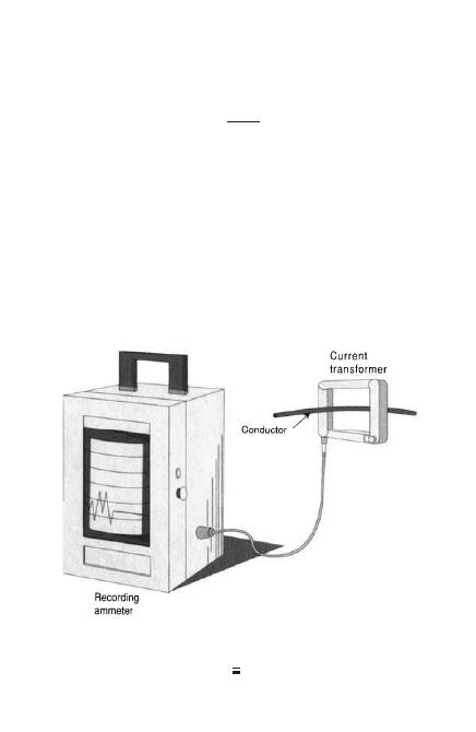
Recording Ammeters
A clamp-on ammeter shows instantaneous current, at
a moment in time. But often when troubleshooting
electrical equipment and systems, it is more useful
to have a record of current over a period of time.
Figure 1-2 shows a recording ammeter used for this
5
1-2
Recording ammeter.
purpose. It has a current-sensing element similar to
clamp-on ammeters, but produces a chart or graph
showing current changes over time.
Voltmeters
The unit of electromotive force (EMF) is the volt (V).
One volt is the pressure that, if applied to an electri-
cal circuit having a resistance of 1 Ω, produces a cur-
rent of 1 A.
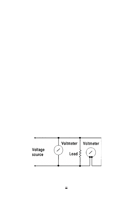
Connect a voltmeter across the terminals at the
place where the voltage is to be measured, as shown
in Figure 1-3. Never connect a voltmeter across a cir-
cuit with a voltage higher than the rating of the
instrument. Doing so can damage the meter, or in
extreme cases cause the voltmeter to explode.
DC Circuits
When measuring voltage in a DC circuit, always
observe proper polarity. The negative lead of the volt-
meter must be connected to the negative terminal of
the DC source, and the positive lead to the positive
6
1-3
Connecting a voltmeter
to a circuit.
terminal. If the leads are connected to opposite ter-
minals, the needle will move in the reverse direction.
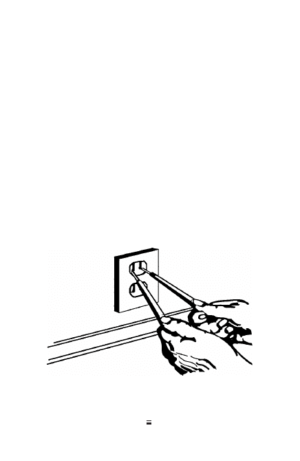
AC Circuits
Since voltage constantly reverses polarity in an AC cir-
cuit, there is no need to observe polarity when mea-
suring voltage on ac circuits (Figure 1-4).
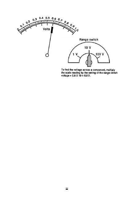
Voltage Ranges
Many analog voltmeters have two or more voltage
ranges that can be read on a common scale, such as 0 to
150 V, 0 to 300 V, and 0 to 600 V (Figure 1-5). When
using a multirange voltmeter, always select a higher
range than needed to assure that the meter won’t be
damaged. Then, if the initial reading indicates that a
lower scale is needed to obtain a more accurate read-
ing, switch the voltmeter to the next lowest range.
7
1-4
Checking voltage at a 125-VAC duplex
receptacle.
One reason that analog voltmeters have multiple
ranges is that readings are more accurate on the upper
half of the scale. Thus, if they only had a single 0- to
600-V range, lower voltages would be harder to read
accurately.
Voltmeter Applications
Voltmeters are used for troubleshooting circuits,
circuit tracing, and measuring low resistance. For
example, a common cause of electrical problems is
low voltage at the supply terminals of equipment; this
usually occurs for one or more of the following
reasons:
●
Undersized conductors
●
Overloaded circuits
●
Transformer taps set too low
8
1-5
Multirange, one-scale voltmeter.

Low-Voltage Test
When making a low-voltage test, first take a reading
at the service entrance. For example, if the main ser-
vice is rated 120/240, single-phase, three-wire, the
voltage reading between phases (ungrounded conduc-
tors) should be 230 to 240 V. If the reading is much
lower than 230 V, the electric utility company should
be contacted to correct the problem. However, if the
reading at the main service is between 230 and 240 V,
the next procedure is to check the voltage reading at
various outlets throughout the system.
When low-voltage problem is measured on a cir-
cuit, leave the voltmeter terminals connected across
the line and begin disconnecting all the loads con-
nected to that circuit, one at a time. If the problem
disappears after several of the loads have been discon-
nected, the circuit is probably overloaded (thus caus-
ing excessive voltage drop). Steps should be taken to
reduce the load on that circuit or else increase con-
ductor wire size to accommodate the load.
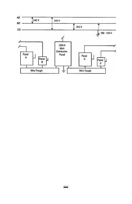
Ground Fault
Ground faults are another common problem. Assume
that a small industrial plant has a three-phase, three-
wire, 240-V, delta-connected service. The service
equipment is installed, as shown in Figure 1-6. Under
proper operating conditions, the voltmeter should
read 240 V between phases (A-B, B-C, and A-C), and
approximately 150 V between each phase to ground.
However, if checking with voltmeter indicates that
two phases have a voltage of 230 V to ground and the
9
third phase is only 50 V to ground, then the phase
with the lowest reading (50 V) has a partial ground or
ground fault. Follow these steps to correct the ground
fault:
Step 1. Connect one voltmeter lead to the
grounded enclosure of the main distribu-
tion panel and the other to the phase ter-
minal that indicated the ground fault.
Step 2. Disconnect switch A and check the volt-
meter reading. If no change is indicated,
disconnect switch B, switch C, and so on,
until the voltmeter shows a change (i.e.,
a reading of approximately 150 V from
phase to ground).
Step 3. Assuming the voltmeter indicates this
reading when switch D is thrown to the
10
1-6
Diagram of a small industrial electric service.
OFF position, we then know that the
ground fault is located somewhere on
this circuit.
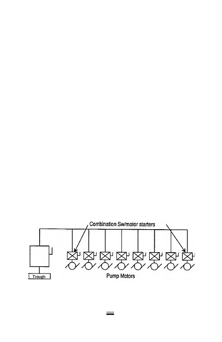
Step 4. Switch D disconnects the 400-A circuit
feeding eight 15-hp motors and con-
nected as shown in Figure 1-7. One volt-
meter lead is connected to the grounded
housing of switch D and the other lead
to one of the phase terminals. The switch
is then turned on. Check each phase ter-
minal until the one with the ground
fault is located.
Step 5. Then, one at a time, disconnect the motors
from the circuit until the one causing the
trouble is found. In other words, when the
motor or motor circuit with the ground
fault is disconnected, the voltmeter will
indicate a normal voltage of approximately
150 V from phase to ground.
11
1-7
Wiring diagram for eight 15-hp pump motors
fed from a 400-A safety switch.
Step 6. Repair the faulty motor or motor circuit
according to standard maintenance proce-
dures. When testing electrical circuits with
a voltmeter, it is usually best to begin at
the main service equipment. First, test the
voltage on the line side to see if the incom-
ing service is “hot”; if it is, then test the
main fuses or circuit breakers. Check by
testing across diagonally from the line to
the load side, as shown in Figure 1-8.
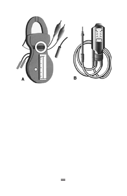
There are various types of analog voltmeters;
Figure 1-9 shows two common designs. Meter A is a
combination volt-ohm-ammeter with a conventional
swinging pointer to indicate the reading; meter B has
an audible indicator—similar to the “ting” of an air
gauge—and gives only approximate voltage readings.
12
1-8
Testing fuses with a voltmeter.
Megohmmeters
The megohmmeter (commonly called a megger in the
field) is used to measure the resistance of insulation in
megohms (thousands of ohms). Test results indicate the
presence of dirt, moisture, and insulation deterioration.
Megohmmeter instruction manuals provide detailed
information about connecting to and testing various
types of equipment. The following sections provide gen-
eral guidance for common types of troubleshooting tests.
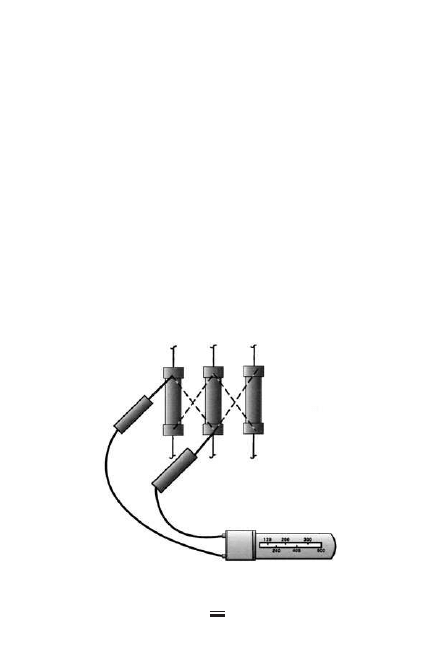
Testing Power Cables
Figure 1-10 shows how to test cable insulation using
a megger. After both ends of the cable have been
13
1-9
Common types of voltmeters.
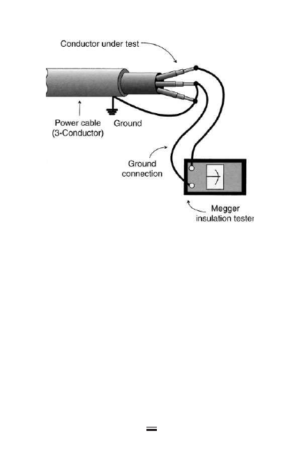
disconnected, test the conductors one at a time, by
connecting one of the leads to the conductor under test
and connecting the remaining conductors (within
the cable) to ground and then to the other (ground)
test lead.
Testing DC Motors and Generators
Disconnect a DC motor and a DC generator from its
load. Then attach the negative test lead of the megohm-
meter to the machine ground and the positive lead to
the brush rigging. Measuring the insulation resistance
in this manner indicates the overall resistance of all
components of the unit.
14
1-10
Testing power cable.
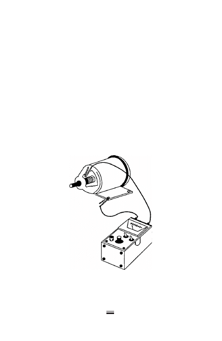
To measure the insulation resistance of the field or
armature alone, either remove the brushes or lift
them free of the commutator ring and support the
brushes using a suitable insulator. Connect one test
lead to the frame ground and the other to one of the
brushes. Insulation resistance of the field alone will
then be indicated, as shown in Figure 1-11. With the
brushes still removed from the commutator ring, con-
nect one of the megger test leads to one of the seg-
ments of the commutator and the other to the frame
ground. The insulating resistance of the armature
alone will then be indicated. This test may be repeated
for all segments of the commutator.
15
1-11
Megger connections
for testing DC motors
and generators.
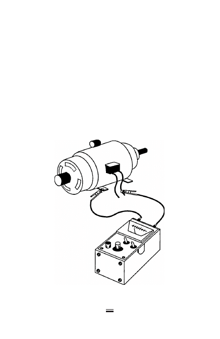
Testing AC Motors
To test an AC motor, first disconnect the motor from
its power source, either by using the switch or by dis-
connecting the wiring at the motor terminals. If the
switch is used, remember that the insulation resis-
tances of the connecting wire, switch panel, and con-
tacts will all be measured at the same time. Connect the
positive megger lead to one of the motor lines and the
negative test lead to the frame of the motor, as shown
in Figure 1-12. Compare meter readings to the estab-
lished insulation resistance minimums.
16
1-12
Method of testing an AC motor.

Testing Circuit Breakers
Disconnect the circuit breaker from the line and con-
nect the megger black lead to the frame or ground.
Check the insulation resistance of each terminal to
ground by connecting the red (positive) lead to each
terminal in turn and making the measurements.
Next, open the breaker and measure the insulation
resistance between terminals by putting one lead on
one terminal and the other on the second for a two-
terminal breaker; for a three-pole breaker, check
among poles 1-2, 2-3, and 1-3.
Testing Safety Switches and Switchgear
Completely disconnect from line and relay wiring before
testing. When testing manually operated switches, mea-
sure the insulation resistance from ground to terminals
and between terminals. When testing electrically oper-
ated switches check the insulation resistance of the coil
or coils and contacts. For coils, connect one megger lead
to one of the coil leads and the other to ground. Next,
test between the coil lead and core iron or solenoid
element.
Testing Ground Resistance
Figure 1-13 shows the simplest method for testing
the resistance of earth. The direct or two-terminal
test consists of connecting terminals P1 and C1 of
the megohmmeter to the ground under test, and
terminals P2 and C2 to an all-metal underground
water-piping system. If the water piping covers a
large area, its resistance should be very low (only be
17
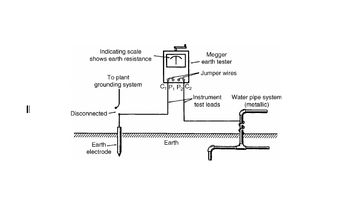
18
1-13
Direct method of earth-resistance testing.

a fraction of an ohm). Thus, the megohmmeter read-
ing will be that of the earth or grounding electrode
being tested.
Miscellaneous Testing Instruments
Ammeters, voltmeters, and megohmmeters are the
most common analog devices used for field testing
and troubleshooting applications. However, several
other specialized types of test instruments should be
mentioned briefly.
Frequency Meter
Frequency is the number of cycles completed each
second by a given AC voltage, usually expressed in
hertz (Hz); 1 Hz = 1 cycle per second.
The frequency meter is used with AC power-
producing devices like generators to ensure that the
correct frequency is being produced. Failure to pro-
duce the correct frequency can result in overheating
and component damage.
Power Factor Meter
Power factor is the ratio of the true power (volt-
amperes) to apparent power (watts), and it depends
on the phase difference between current and voltage.
Three-phase power factor meters are installed in
switchboards. Many utilities charge large commercial
and industrial users a penalty if power factor falls
below 90 percent; so these users try to maintain high
power factor at all times. A high power factor provides
better voltage regulation and stability.
19

Tachometers
A tachometer is a device that indicates or records the
speed of rotating equipment (motors and generators)
in revolutions per minute (rpm). There are several dif-
ferent types:
Vibrating-reed Tachometer
This instrument is simply held against the motor,
turbine, pump, compressor, or other rotating equip-
ment, and the speed is shown by the vibration of a
steel reed, which is tuned to a certain standard
speed.
Photo Tachometer
This instrument aims a light at the rotating shaft on
which there is a contrasting color such as a mark, a
chalk line, or a light-reflective strip or tape. The rota-
tional speed in rpm is read from an indicating scale.
Photo tachometers are especially useful on relatively
inaccessible rotational equipment such as motors,
fans, grinding wheels, and other similar machines
where it is difficult, if not impossible, to make contact
with the rotational unit.
Electric Tachometer
This consists of a small generator that is belted or
geared to the equipment whose speed is to be mea-
sured. The voltage produced in the generator varies
directly with the rotational speed of the generator.
Since this speed is directly proportional to the speed
of the machine under test, the amount of the gener-
ated voltage is a measure of the speed.
20

Footcandle Meter
A footcandle meter consists of a photosensitive ele-
ment and a meter that indicates the average illumina-
tion of a room or other space in footcandles. Typical
footcandle meters can read light intensity from 1 to
500 footcandles or more.
To use the footcandle meter, first remove the cover.
Hold the meter in a position so the cell is facing toward
the light source and at the level of the work plane where
the illumination is required. The shadow of your body
should not be allowed to fall on the cell during tests. A
number of such tests at various points in a room or area
will give the average illumination level in footcandles.
Readings are taken directly from the meter scale.
Electrical Thermometers
For the measurement of temperatures, there are three
basic types of electrical thermometers.
1. Resistance thermometers operate on the
principle that the resistance of a metal varies
in direct proportion to its temperature. They
are normally used for temperatures up to
approximately 1500°F.
2. Thermocouples operate on the principle that
a difference in temperature in different metals
generates a voltage, and are used for measur-
ing temperatures up to about 3000°F.
3. Radiation pyrometers and optical pyrome-
ters are generally used for temperatures above
3000°F. They combine the principle of the
21

thermocouple with the effect of radiation of
heat and light.
Phase-Sequence Indicator
A common phase-sequence indicator is designed for
use in conjunction with any multimeter that can
measure AC voltage. Most can be used on circuits
with line voltages up to 550 VAC, provided the instru-
ment used with the indicator has a rating this high.
To use the phase-sequence indicator, set the multi-
meter to the proper voltage range. This can be deter-
mined (if it is not known) by measuring the line
voltage before connecting the phase-sequence indica-
tor. Next, connect the two black leads of the indica-
tor to the voltage test leads of the meter. Connect the
red, yellow, and black adapter leads to the circuit in
any order and check the meter for a voltage reading.
If the meter reading is higher than the original cir-
cuit voltage measured, then the phase sequence is
black-yellow-red. If the meter reading is lower than
the original circuit voltage measured, then the phase
sequence is red-yellow-black. If the reading is the
same as the first reading, then one phase is open.
Cable-Length Meters
Cable-length meters measure the length and condi-
tion of a cable by sending a signal down the cable and
then reading the signal that is reflected back. These
instruments are also called time-domain reflectome-
ters (TDRs). A similar instrument used to measure the
length of fiber optic cables is called an optical time-
domain reflectometer (ODTR).
22
Power Quality Analyzers
Power quality analyzers are portable test instruments
similar in construction to the digital multimeters
described in greater detail in Chapter 2. However, unlike
DMMs, which typically measure only one property of
electrical circuits at a time, power quality analyzers
have dual probes that allow both voltage and current to
be measured simultaneously. Power quality analyzers
can also measure frequency and harmonics.
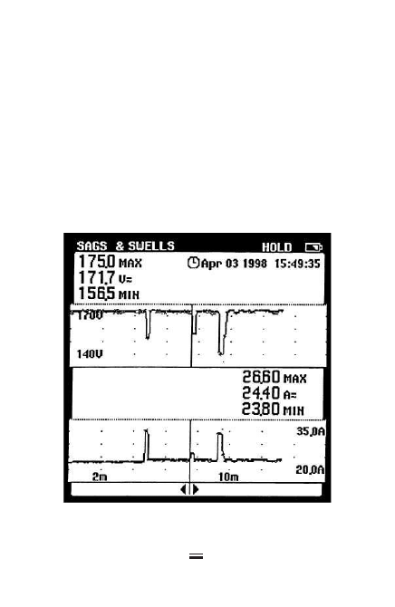
The results of these readings are displayed graphi-
cally, as shown in Figure 1-14. The ability to measure
23
1-14
Power quality analyzer display showing voltage on
top, current on bottom, and time stamp at upper right.

and display multiple circuit characteristics at the same
time is useful in troubleshooting power quality prob-
lems in power distribution systems. This subject is
covered more fully in Chapter 9.
24

T
he five core functions of handheld meters are
measuring AC and DC voltage, AC and DC cur-
rent, and resistance. Digital multimeters (DMMs) con-
taining microprocessors perform these functions, but
their built-in computing power allows them to offer
other capabilities as well:
●
Greater accuracy
●
Better displays
●
Accessory adapters for taking additional
types of measurements
●
Data-handling capabilities
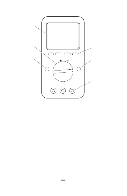
Figure 2-1 shows a typical DMM. The range of fea-
tures, options, and accessories offered on DMMs varies
widely from one brand and model to the next. The
most important are summarized in the next sections.
Greater Accuracy
The accuracy of DMM readings is typically from 0.5 to
0.1 percent, and results can be displayed to two or three
decimal places. While this level of accuracy is not always
needed for field troubleshooting of electromechanical
25
Copyright © 2007, 2000, 1996 by The McGraw-Hill Companies, Inc.
Click here for terms of use.
26
Hz
A
HOLD
RANGE
OFF
V
A
COM
V
⍀
/
1 LCD display with numerical readout.
2 Measurement function knob.
3 Soft-keys—Use with measurement function knob
to select measurements.
4 Range button—Use to set measurement range.
5 Hold button—Use to freeze display.
6 Input connectors.
Note: Some DMMs have a separate function knob
setting and/or input connector for A/mA..
1
2
4
3
5
6
2-1
Digital multimeter (DMM).
equipment, it can be useful in applications involving
electronic circuits.
Better Displays
Digital multimeter displays show numerals and
graphical patterns (such as waveforms) rather than

swinging needles. Displays are large enough to read
from a distance, and some can display two or more
items simultaneously, such as voltage and frequency.
Most DMMs have a liquid-crystal diode display that
expresses readings in contrasting shades of gray. Many
models also have a backlighting switch for taking read-
ings under poorly lighted areas. Maximum display
readouts are always one digit less than the marked
range. For example, the 200-Ω resistance range reads
between 0.0 and 199.9 Ω (Figure 2-3). If higher resis-
tance is present, “OL” or “1” (overlimit or out-of-range
indication) shows in the display. When this happens,
the rotary switch should be rotated to a higher range.
Hold, Freeze, or Capture Mode
On many DMMs, pressing a “hold” button freezes a
reading on the display screen so that the meter can be
taken to a more convenient area for viewing. This fea-
ture is particularly useful in tight spaces with poor vis-
ibility, or when it isn’t convenient to read the display
at the same time you’re taking a measurement on a
circuit or piece of electrical equipment.
Construction and Convenience Features
Most DMMs have a shock-resistant heavy-duty case
with a belt holster, and a tilt stand for placing on flat
surfaces such as a table. Many also have handles that
allow them to be hung at eye level, an advantage in
many troubleshooting applications where space is
tight. DMMs are very rugged and can last for years of
trouble-free operation under heavy-duty use.
27

Many units can operate with the same 9 V battery
for 2000 to 3000 hours because the solid-state circuits
and LCD display have a very low current drain. Some
models constantly display a battery status icon on the
screen. In other models, a “Lo Bat” warning appears
or the decimal point in the digital display blinks
when the battery is nearing its end of life.
Function Selection
DMMs have a dial or rotary switch that lets you select
basic measurement functions (such as voltage,
current, resistance, frequency, and temperature).
Higher-priced DMMs also have either four or eight
“soft keys.” These are push buttons whose function
depends upon the type of measurement selected.
When the dial is rotated to select a basic measure-
ment function, such as current, some or all of these
soft keys may become active. When this happens,
the purpose of that key is displayed at the bottom of
the LCD display (i.e., just above the soft keys). For
some measurement functions, not all soft keys will be
active.
Inputs and Test Leads
Most DMMs have three test jacks or inputs: voltage (V),
current (A), and common or return (COM). The inputs
marked V and A are normally colored red, as are the
various test leads that plug into them. The common
input, which is used for all measurement functions, is
normally colored black, as is the common test lead
that plugs into it.
28

NOTE: Some units also have a fourth separate input
for current measurements in the milliampere (mA) or
microampere (µA) range.
Accessories
DMM manufacturers offer a wide array of accessories
that both extend measurement ranges and allow the
instrument to be used for additional types of mea-
surements, including:
●
Power
●
Power factor
●
Energy (kWh)
●
Harmonics
●
Temperature (single probe, and dual probe
for differential)
●
Light intensity
●
Relative humidity
●
Carbon monoxide (CO)
●
Airflow
General Instructions for Using
Digital Multimeters
Because exact capabilities and features of different
DMMs vary, it is important to read the manufacturer’s
manual supplied with the unit. The following proce-
dures apply to DMMs generally.
Measuring Voltage
Select a voltage measurement range. Connect test
leads to the V and COM inputs. Place the DMM in
29
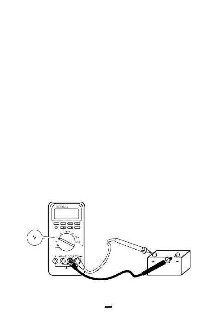
parallel with the voltage source and load to measure
voltage (Figure 2-2). Never place the meter in series
with the circuit when measuring voltage.
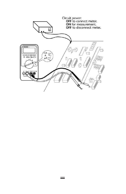
Measuring Current
Select a current measurement range. Connect test leads
to the A and COM inputs. Place the DMM in series with
the voltage source and load to measure current. Never
place the meter across (in parallel with) the circuit
when measuring amperes. The current in solid-state cir-
cuits such as printed circuit boards is measured in mil-
liamperes (mA) or microamperes (µA) (Figure 2-3).
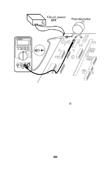
Measuring Resistance
Select resistance test (Ω). Plug the red test lead into the
voltage (V) input and the black lead into the common
(COM) input. Place the probe tips across the suspected
resistor or leaky component. A good resistor should
read within plus or minus 10 percent of its rating.
30
2-2
Measuring voltage.
Thus, a sound 330-Ω resistor would register between
300 and 360 Ω (suspect a burned resistor if the read-
ing is less than 300 Ω). It may be necessary to isolate
the resistor or other component from the circuit to
get an accurate reading (Figure 2-4).
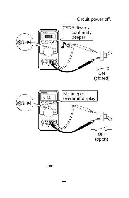
Testing Continuity
Select resistance test (Ω). Connect test leads to the V
and COM inputs. Some DMMs sound a constant tone
or noise when making continuity and diode tests. A
constant tone indicates proper continuity. No tone (or
a broken, stop-start sound) indicates an open circuit,
intermittent faults, or loose connections (Figure 2-5).
31
2-3
Measuring current.
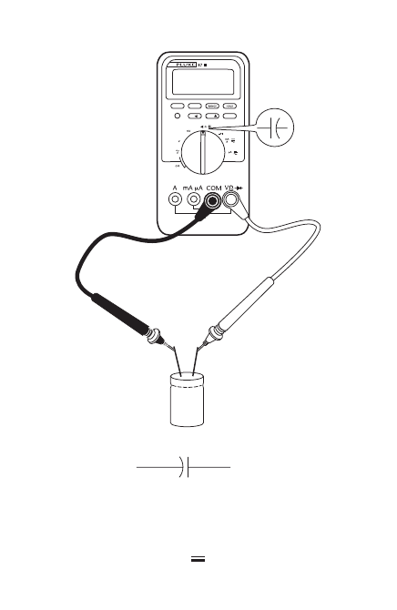
Measuring Capacitance
Select capacitance measurement (
). Connect test
leads to the V and COM inputs. Capacitors should be
isolated from the circuit to provide accurate DMM
measurements (Figure 2-6). Discharge large filter
capacitors before attempting to measure them.
Measuring Frequency
Select frequency measurement (Hz). Connect test
leads to the V and COM inputs. As with other DMM
measurements, start at the highest band and switch
down to the correct frequency range.
32
2-4
Measuring resistance.
Testing Diodes
Select diode test (
). Connect test leads to the V and
COM inputs. Some DMMs have an audible tone for the
33
2-5
Testing for continuity.
34
+
–
2-6
Measuring capacitance.
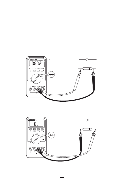
diode test. Touch the red probe to the anode and the
black test probe to the cathode terminal of the diode.
The cathode may be marked with a black or white line
at one end of the diode (Figure 2-7). A normal silicon
diode reading will indicate only an overlimit measure-
ment (OL or 1) if the test leads are reversed.
35
Typical
reading
Test leads OK
+
–
Leads reversed
+
–
2-7
Testing diodes.

Digital Multimeter Safety Features
Hand-held test meters should never be connected to
any electrical equipment or system operating at a
voltage that exceeds the meter’s rating. While this is
an important safety precaution when using any
meter, it is even more important with DMMs.
Digital meters are more sensitive than older analog
models to transient overvoltages caused by nearby
lightning strikes, utility switching, motor starting,
and capacitor switching. High-voltage transients can
damage the electronic circuitry inside DMMs, and in
severe cases cause meters to explode.
DMMs have internal fuses that function to protect
the test instrument (and the person using it) from
harm when taking readings on systems of higher volt-
age or current rating than the DMM.
However, it is still extremely important never to try to
take a reading on a system whose voltage or current is
higher than the rating of the DMM itself.
Underwriters Laboratories Inc. has established
safety ratings for DMMs. UL standard 3111-1 defines
four energy-rating categories for test and measure-
ment equipment, with CAT IV offering the highest
level of protection.
CAT IV covers utility connections and all outdoor
conductors (because of lightning hazards). Examples
include service entrance equipment, watt-hour meters,
and switchboards/switchgears.
CAT III covers power distribution equipment
within buildings and similar structures. This includes
panelboards, feeders, busways, motors, and lighting.
36

37
CAT II covers single-phase, receptacle-connected
loads located more than 10 m from a CAT III power
source or more than 20 m from a CAT IV source.
CAT I covers electronic and low-energy equipment.
DMMs are certified to these four categories by UL
and other independent testing laboratories. The certi-
fication level is marked directly on the DMMs, and
often included in advertising for them. Higher-rated
meters can safely be used for lower-level measurement
functions.
IMPORTANT
The category number of a DMM is more important
than its voltage rating when determining the
degree of protection that it provides. In other
words, a CAT III, 600 V meter offers better protec-
tion against high-energy transients than a CAT II,
1000 V meter.
General Safety Precautions for
Using Digital Multimeters
●
When schematic drawings, building plans,
or other documentation is available, check
for expected ranges of voltage, current,
resistance, and other properties before
taking measurements with the DMM.
Rotate the function switch to the appro-
priate range.
●
If the appropriate range for a given mea-

surement is not known, start at the highest
scale for voltage, current, and so on. Select
progressively lower ranges until the mea-
surement falls within the correct range.
●
If the overlimit display (OL or 1) comes
on, turn to a higher measurement scale.
●
Remove test leads from the circuit or
device being tested when changing the
measurement range.
●
Resistance and diode measurements
should only be taken in de-energized
circuits.
●
Discharge all capacitors before taking
capacitance readings with a DMM.
38

Much of the work performed by electricians and tech-
nicians involves the repair and maintenance of elec-
trical equipment and systems. To maintain such
systems at peak performance, workers must have a
good knowledge of what is commonly referred to as
troubleshooting—the ability to determine the cause
of a malfunction and then correct it.
Troubleshooting covers a wide range of problems,
from small jobs such as finding a short circuit or ground
fault in a home appliance to tracing out defects in a
complex industrial installation. The basic principles
used are the same in either case. Troubleshooting
requires a thorough knowledge of electrical theory and
testing equipment, combined with a systematic and
methodical approach to finding and diagnosing
problems.
The following general tips and principles are
intended to help define the troubleshooting process.
Specific types of electrical equipment and systems are
described in later chapters of this book.
39
Copyright © 2007, 2000, 1996 by The McGraw-Hill Companies, Inc.
Click here for terms of use.

Think Before Acting
Study the problem thoroughly, and ask yourself these
questions:
●
What were the warning signs preceding
the trouble?
●
What previous repair and maintenance
work has been done?
●
Has similar trouble occurred before?
●
If the circuit, component, or piece of
equipment still operates, is it safe to con-
tinue operation before further testing?
The answers to these questions can usually be
obtained by:
●
Questioning the owner or operator of the
equipment.
●
Taking time to think the problem through.
●
Looking for additional symptoms.
●
Consulting troubleshooting charts.
●
Checking the simplest things first.
●
Referring to repair and maintenance
records.
●
Checking with calibrated instruments.
●
Double-checking all conclusions before
beginning any repair on the equipment
or circuit components.
The source of many problems is not one part alone,
but the relationship of one part to another. For instance,
a tripped circuit breaker may be reset to restart a piece of
equipment, but what caused the breaker to trip in the
40

41
first place? It could have been caused by a vibrating
“hot” conductor momentarily coming into contact
with a ground, or a loose connection could eventually
cause overheating, or any number of other causes.
Too often, electrically operated equipment is com-
pletely disassembled in search of the cause of a certain
complaint, and all evidence is destroyed during disas-
sembly operations. Check again to be certain an easy
solution to the problem has not been overlooked.
Find and Correct the Cause
of Trouble
After an electrical failure has been corrected in any
type of electrical circuit or piece of equipment, be sure
to locate and correct the cause so the same failure will
not be repeated. Further investigation may reveal
other faulty components. Also be aware that although
troubleshooting charts and procedures greatly help in
diagnosing malfunctions, they can never be com-
plete; there are too many variations and solutions for
a given problem.
Note:
Always check the easiest and obvious things first;
following this simple rule will save time and trouble.
To solve electrical problems consistently, you must
first understand the basic parts of electrical circuits,
how they function, and for what purpose. If you
know that a particular part is not performing its job,

then the cause of the malfunction must be within this
part or series of parts.
Intermittent Faults
Finding and diagnosing intermittent faults, where a
short, open, or other problem occurs only temporarily,
or only under certain conditions, is always a difficult
troubleshooting problem. Two features found on most
DMMs can help with identifying intermittent faults.
Continuity capture mode
This feature is useful for finding intermittent connec-
tions with small gauge wires and wiring bundles, and
even intermittent relay contact. To check for intermit-
tent opens, place the leads across the normally closed
or shorted connection and select Continuity Capture
mode on the DMM. Wiggle the wire(s) and heat the
connection with a heat gun, or cool it with circuit
cooler to make the intermittent open appear. When
the open is captured (as short as 250 µs), the display
shows a transition from open to a short.
Intermittent shorts can be found the same way, by
connecting to a normally open circuit and using the
wiggling and heating/cooling techniques to capture
the short. The only difference is that the transition
lines will go from the bottom of the display to the top.
Recording mode
Sometimes intermittent faults cannot be successfully
induced while observing the DMM display. Some
higher-end units have a recording mode with a
date and time stamp. This type of DMM can be left
42
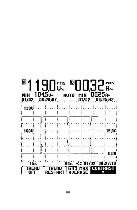
connected to a circuit or piece of electrical equipment
for an extended period of time to record the occurrence
of an intermittent fault. The date and time of occur-
rence may provide clues that allow the electrician or
technician to trace the cause of the fault (Figure 3-1).
Working Safely Is Critical
Electrical troubleshooting is inherently hazardous.
The hazards of working with electricity include
shock and electrocution, fire, and arc-blast injuries.
43
3-1
Recording DMM display.

Arc-blast is a high energy “explosion” that can occur
when something happens such as accidentally
shorting across transformer terminals or the bus
bars in a panelboard—for example, by dropping a
metal screwdriver.
NFPA 70E-2004, Standard for Electrical Safety in the
Workplace, is the governing standard for protection
against electrical hazards in the workplace. Trouble-
shooting is particularly hazardous, because electricians
and technicians are often working on energized (“live”)
equipment and systems.
In addition to electrical hazards, testing and main-
tenance work also involves other dangers such as
falling from roofs and ladders, and accidents with
power tools. Entire books have been written about
electrical safety. This section summarizes essential
safety precautions when performing troubleshooting
on electrical equipment and systems. It is based on
the safety rules of NFPA 70E.
Qualified persons
Article 100 of the National Electrical Code defines a
qualified person as “One who has skills and knowledge
related to the construction and operation of the elec-
trical equipment and installations and has received
safety training on the hazards involved.” NFPA 70E
uses the same definition.
To help prevent accidents and injuries, only quali-
fied persons meeting this definition should perform
electrical troubleshooting work. Untrained, unquali-
fied, persons should never be allowed to do electrical
testing and maintenance.
44

Personal protective equipment
Troubleshooting often involves testing of energized
circuits and equipment. Because of the dangers,
NFPA 70E defines electrical testing as a hazardous
task that should only be performed wearing appro-
priate personal protective equipment (PPE). The
minimum PPE for electrical troubleshooting work is
as follows:
●
Long-sleeved shirt and pants of natural
fibers, such as cotton or wool. Don’t wear
synthetic fabrics such as polyester or
nylon, which can melt and catch fire in
case of an electrical arc-blast.
●
Steel-toed boots.
●
Only plastic hard hats should be worn
for electrical work.
●
Safety goggles or glasses.
●
Work gloves.
In addition, don’t wear metal jewelry such as rings,
wristwatches, chains, and earrings when working
around electrical circuits and equipment. Gold and
silver are excellent conductors of electricity.
Working on energized equipment such as panel-
boards and motor control centers with the covers off
is particularly hazardous. A short-circuit or faulty cir-
cuit breaker in an energized panelboard could result
in an arc-blast, causing severe burns and other injuries
to the workers involved. NFPA 70E requires the fol-
lowing additional PPE when performing “switching
operations” on live electrical equipment:
45

●
Fire-rated (FR) clothing.
●
FR flash jackets or suits with hoods over
the FR clothing.
●
Arc-rated face shields.
●
Hearing protection.
●
Voltage-rated gloves.
●
Voltage-rated tools.
PPE is a complex subject. The correct PPE needed
depends upon the type of work being done, the oper-
ating voltage, and the available fault current. For
complete information about this subject, see NFPA
70E-2004, Standard for Electrical Safety in the Workplace.
Avoid working “live”
Electrical testing must often be performed on ener-
gized circuits and equipment. But the safest technique
for doing tasks such as repairing and replacing faulty
components is to turn the power off. PPE isn’t needed
when there are no electrical hazards to protect
against. So, the simplest safety rule for electrical main-
tenance work is—Don’t work live!
Lockout/tagout
When electrical systems are de-energized to perform
maintenance work safely, precautions must be taken
to insure that circuits are not accidentally turned back
on while the work is going on.
Lockout/tagout is the preferred method of control-
ling energy sources to minimize hazards to personnel.
The details are complex, and beyond the scope of
this book. But every company should have an official
lockout/tagout procedure, which should always be
46

followed when electrical circuits are de-energized
during construction or maintenance work. For more
information, refer to NFPA 70E, Annex G “Sample
Lockout/Tagout Procedure.”
47

This page intentionally left blank

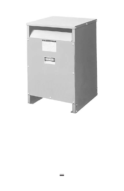
D
ry-type transformers are a part of most electrical
installations. They range in size from small doorbell
transformers to three-phase 25-kVA units installed in
electrical closets (Figure 4-1) to large, free-standing units
rated at several hundred kVA (Figure 4-2). Electricians
must know how to test for and diagnose problems that
develop in transformers—especially in the smaller, dry-
type power-supply or control transformers.
Open Circuit
If one of the windings in a transformer develops a
break or “open” condition, no current can flow and
therefore, the transformer will not deliver any output.
The symptom of an open-circuited transformer is that
the circuits, which derive power from the transformer,
are de-energized or “dead.” Use an AC voltmeter or
DMM to check across the transformer output termi-
nals, as shown in Figure 4-3. A reading of 0 V indi-
cates an open circuit.
Then take a voltage reading across the input ter-
minals. If voltage is present, this indicates that one
49
Copyright © 2007, 2000, 1996 by The McGraw-Hill Companies, Inc.
Click here for terms of use.
50
of the transformer windings is open. However, if
there is no voltage reading on the input terminals
either, then the open must be somewhere else on the
line side of the circuit; possibly a disconnect switch
is open.
4-1
Dry-type transformer (25-kVA,
three-phase). (Courtesy of Square D
Company.)
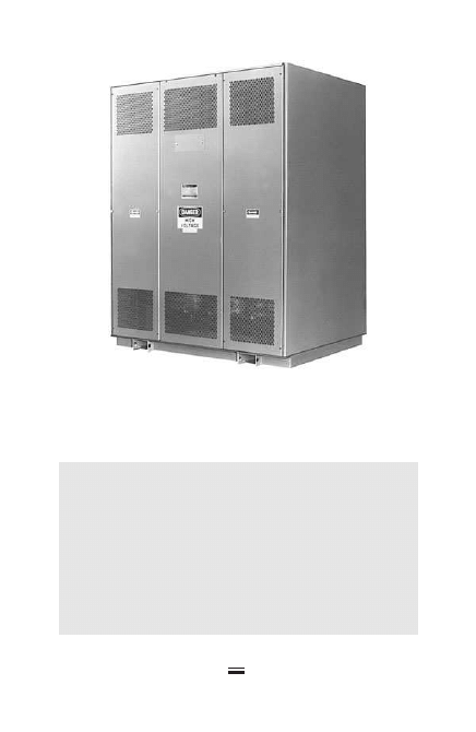
51
4-2
Dry-type transformer (300-kVA,
three-phase). (Courtesy of Square
D Company.)
WARNING!
Make absolutely certain that your testing instru-
ments are designed for the job and are calibrated
for the correct voltage. Never test the primary
side of any transformer over 600 V unless you are
qualified, have the correct high-voltage testing
instruments, and the test is made under the
proper supervision.
However, if voltage is present on the line or pri-
mary side and no voltage is on the secondary or load
side, open the switch to de-energize the circuit, and
place a warning tag (tag-out and lock) on this switch
so that it is not inadvertently closed again while
someone is working on the circuit. Disconnect all of
the transformer primary and secondary leads and
check each winding in the transformer for continuity
(a continuous circuit), as indicated by a resistance
reading taken with an ohmmeter.
Continuity is indicated by a relatively low resistance
reading on control transformers, while an open wind-
ing will be indicated by an infinite resistance reading
(OL or 1). In most cases, such small transformers will
52
Volt
0.0
4-3
Checking for an open circuit
in a transformer.

have to be replaced, unless of course the break is acces-
sible and can be repaired.
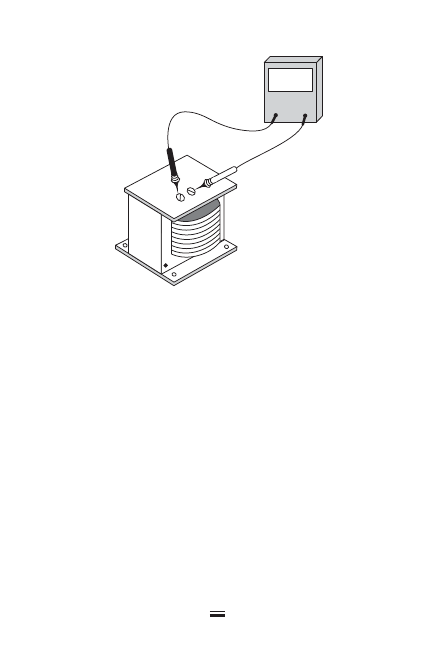
Ground Fault
Sometimes a few turns in the secondary winding of a
transformer experience a partial short, which in turn
causes a voltage drop across the secondary. The usual
symptom of this condition is transformer overheating
caused by large circulating currents flowing in the
shorted windings.
The easiest way to check this condition is with a
voltmeter. Take a reading on the line or primary side of
the transformer first to make certain normal voltage is
present. Then take a reading on the secondary side. If
the transformer has a partial short or ground fault, the
secondary voltage reading will be lower than normal.
Replace the faulty transformer with a new one and
again take a reading on the secondary. If the voltage
reading is now normal and the circuit operates satisfac-
torily, leave the replacement transformer in the circuit,
and either discard or repair the original transformer.
Complete Short
Occasionally a transformer winding becomes com-
pletely shorted. In most cases, this activates the
overcurrent-protective device (circuit breaker or fuse)
and de-energizes the circuit. But in some cases, the
transformer may continue trying to operate with
excessive overheating—due to the very large circulat-
ing current. This heat will often melt the insulation
inside the transformer, which is easily detected by the
odor. Also, there will be no voltage output across the
53

shorted winding and the secondary circuit supplied
by that winding will be dead.
The short may be in the external secondary circuit or
it may be in the transformer’s winding. To determine its
location, disconnect the secondary circuit from the
winding and take a reading with a voltmeter. If the volt-
age is normal with the external circuit disconnected,
then the problem is in the external circuit. However, if
the voltage reading is still zero across the secondary
leads, the transformer is shorted and must be replaced.
Grounded Windings
Insulation breakdown is quite common in older
transformers—especially those that have been over-
loaded. At some point, insulation breaks or deterio-
rates and bare conductors become exposed. The
exposed wire often comes into contact with the trans-
former housing and grounds the winding.
If a winding develops a ground, and a point in the
external circuit connected to this winding is also
grounded, part of the winding will be shorted out.
The symptoms are overheating, usually detected by
feel or smell, and a low voltage reading as indicated
on a voltmeter scale. In most cases, transformers with
this condition must be replaced.
A megohmmeter is used to test for this condition.
Disconnect the leads from both the primary and sec-
ondary windings. Tests can then be performed on
either winding by connecting the megger negative
test lead to an associated ground and the positive test
lead to the winding to be measured.
54
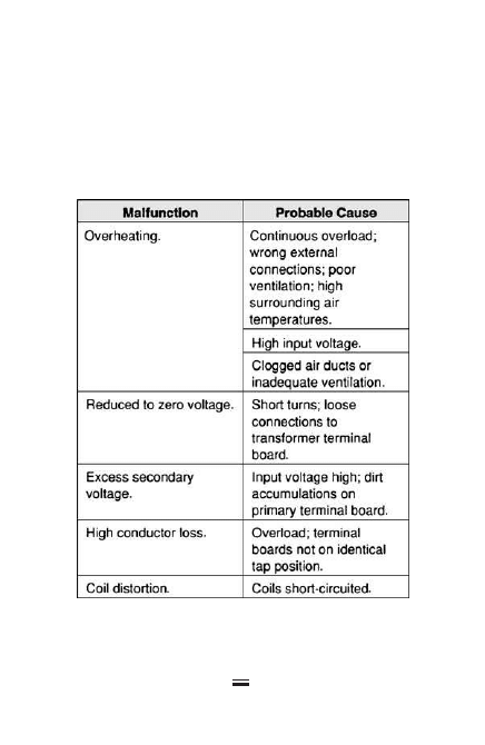
55
4-4
Troubleshooting chart for dry-type
transformers.
Insulation resistance should then be measured
between the windings themselves, by connecting one
test lead to the primary and the second test lead to
the secondary.
The troubleshooting chart in Figure 4-4 covers the
most common dry-type transformer problems.
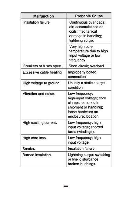
56
4-4
Troubleshooting chart for dry-type
transformers. (Continued)

T
he National Electrical Code (Article 100) defines
luminaire as follows:
Luminaire. A complete lighting unit consisting of a
lamp or lamps together with the parts designed to
distribute the light, to position and protect the lamps
and ballast (where applicable), and to connect the
lamps to the power supply.
A typical commercial, industrial, or institutional
building contains hundreds or even thousands of
luminaires. For this reason, troubleshooting lumi-
naires is an important part of the typical maintenance
electrician’s work. This chapter covers the three most
common types of lighting used in commercial, indus-
trial, and institutional applications:
●
Fluorescent luminaires
●
Incandescent luminaires
●
High-intensity discharge (HID) luminaires
57
Copyright © 2007, 2000, 1996 by The McGraw-Hill Companies, Inc.
Click here for terms of use.

58
Troubleshooting Fluorescent
Luminaires
Fluorescent lamps are electrical discharge lighting
sources. Current flows in an arc through a glass tube
filled with mercury vapor between contacts called
cathodes at each end of the tubular lamp. The inside of
the tube is coated with a powder called phosphor that
glows when excited by ultraviolet radiation, produc-
ing visible light.
Fluorescent lamps require an auxiliary component
called a ballast to operate. The ballast performs two
functions:
1. It produces a jolt of high voltage to vaporize
the mercury inside the lamp and start the arc
from one end to the other.
2. Once a lamp is started, the ballast limits current
to the lower value needed for proper operation.
There are many different types of fluorescent lamps
and ballasts. Older types of ballasts known as core-and-
coil are still widely used, but electronic ballasts are
also common.
Almost all fluorescent luminaires installed in mod-
ern construction use rapid start and instant start lamps.
An older type of preheat fluorescent lamp uses a
separate component called a starter to heat the lamp
cathodes before the arc is struck. Preheat lamps and
fixtures are rarely used in modern commercial light-
ing systems, and they are not included in this trou-
bleshooting guide.

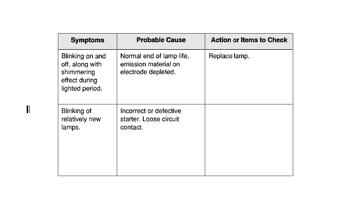
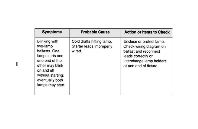
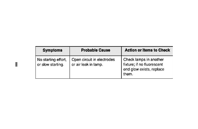
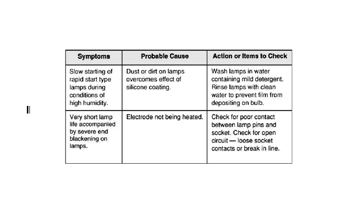
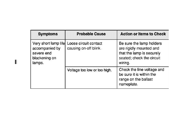
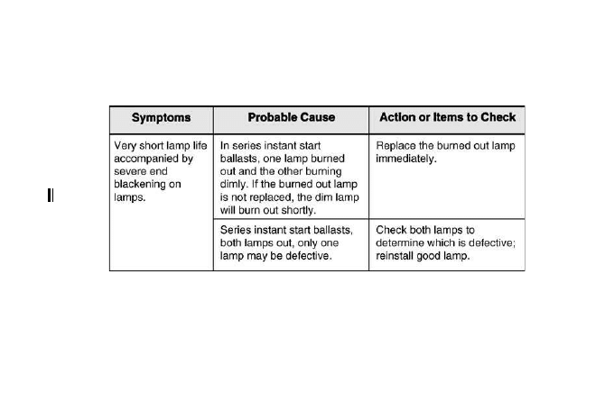
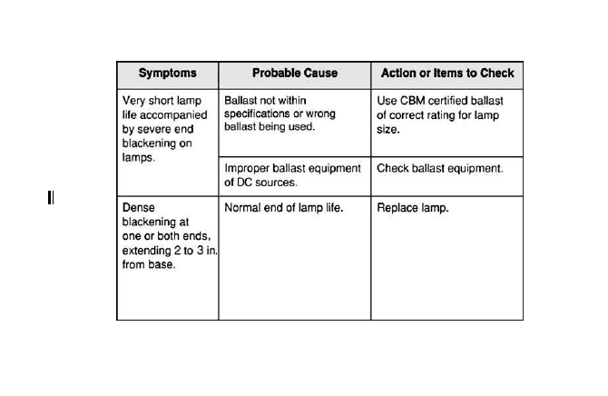
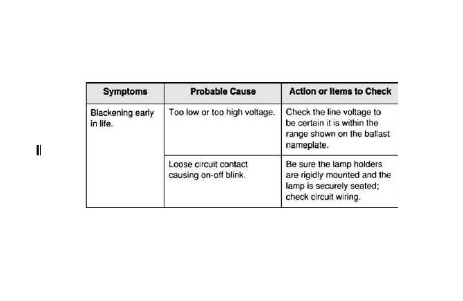
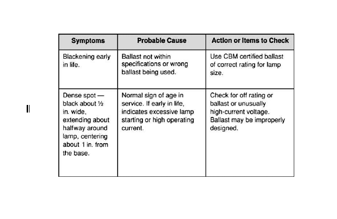
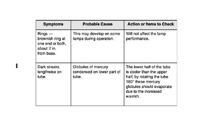
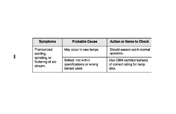
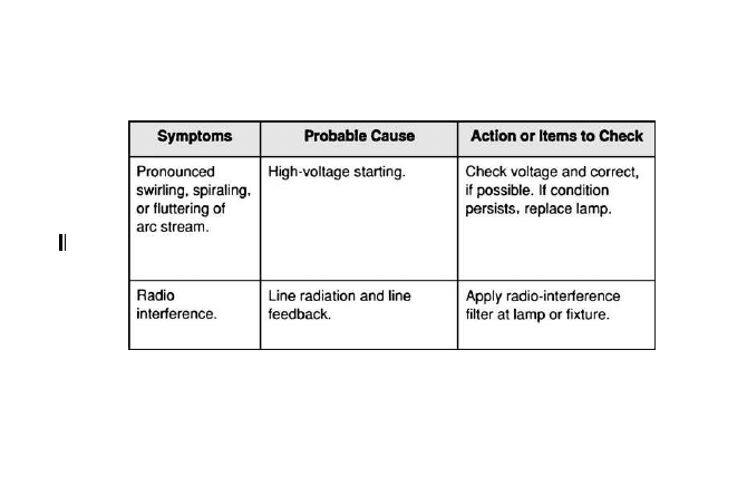
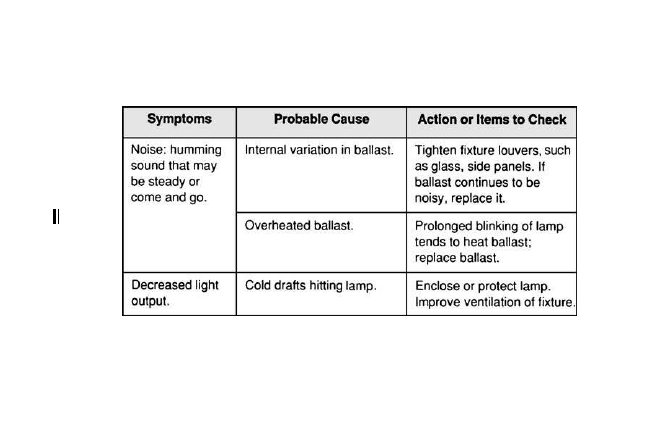
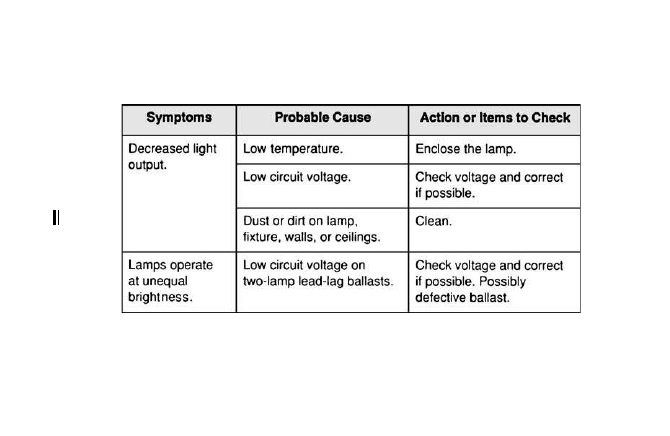
The troubleshooting chart (Figure 5-1) lists faults,
probable causes, and corrective action to take while
troubleshooting fluorescent luminaires.
Troubleshooting Incandescent
Luminaires (Including
Tungsten-Halogen)
Although fluorescent and HID luminaires are now
used for most area lighting applications in commer-
cial, industrial, and institutional facilities, incandes-
cent luminaires are still widely used for decorative
and accent lighting.
●
Traditional incandescent lamps are made
in thousands of different types and colors
from a fraction of a watt to over 10 kW
each, though the types most commonly
used for general lighting applications are
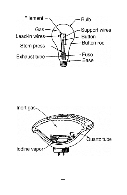
rated between 40 and 200 W (Figure 5-2).
Traditional incandescent produce light
by means of a filament heated to incan-
descence (white glow) in a vacuum.
●
Tungsten-halogen lamps (also known as
quartz-halogen and quartz-iodide) use a
lamp-within-a-lamp design (Figure 5-3).
The inner quartz envelope is filled with
iodine vapor, which retards evaporation
of the tungsten filament and thus pro-
longs lamp life. Tungsten-halogen lamps
aren’t physically interchangeable with
other types of incandescent lamps and
require special luminaires.
59
60
Seat lamp securely;
indicator bumps should be
directly over socket slot.
Check if lamp holders are
rigidly mounted and properly
spaced; tighten all
connections.
5-1 Troubleshooting chart for fluorescent luminaires.
61
5-1 Troubleshooting chart for fluorescent luminaires. (Continued)
62
5-1 Troubleshooting chart for fluorescent luminaires. (Continued)
63
5-1 Troubleshooting chart for fluorescent luminaires. (Continued)
64
5-1 Troubleshooting chart for fluorescent luminaires. (Continued)
65
5-1 Troubleshooting chart for fluorescent luminaires. (Continued)
66
5-1 Troubleshooting chart for fluorescent luminaires. (Continued)

67
5-1 Troubleshooting chart for fluorescent luminaires. (Continued)
68
5-1 Troubleshooting chart for fluorescent luminaires. (Continued)
69
5-1 Troubleshooting chart for fluorescent luminaires. (Continued)
70
5-1 Troubleshooting chart for fluorescent luminaires. (Continued)
71
5-1 Troubleshooting chart for fluorescent luminaires. (Continued)
72
5-1 Troubleshooting chart for fluorescent luminaires. (Continued)
73
5-1 Troubleshooting chart for fluorescent luminaires. (Continued)
74
5-1 Troubleshooting chart for fluorescent luminaires. (Continued)
75
5-2 Basic components of an incandescent lamp.
5-3 Basic components of a tungsten-halogen lamp.

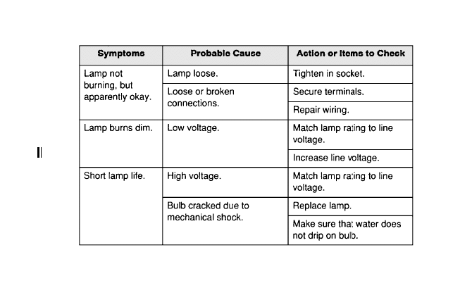
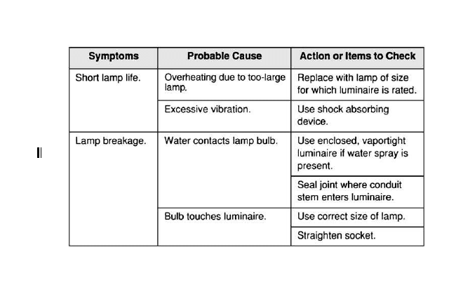
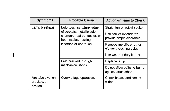
The troubleshooting charts to follow (Figure 5-4)
cover the most commonly encountered problems
with incandescent luminaires.
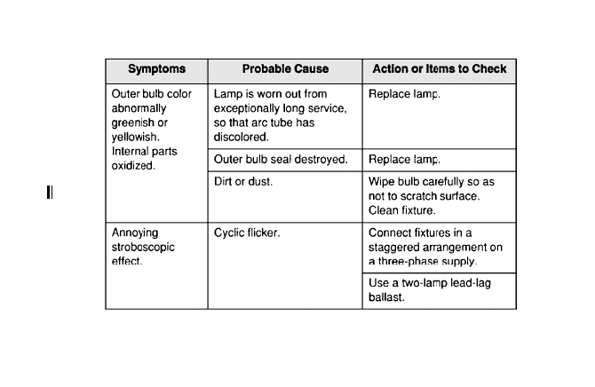
Troubleshooting HID Luminaires
High-intensity discharge (HID) lamp is a generic term
for lamps that have arc tubes and are supplied by
ballasts. HID lamp types include mercury vapor, metal
halide, and high-pressure sodium. Low-pressure
sodium lamps aren’t actually HID, but use ballasts and
resemble HID lamps in other ways.
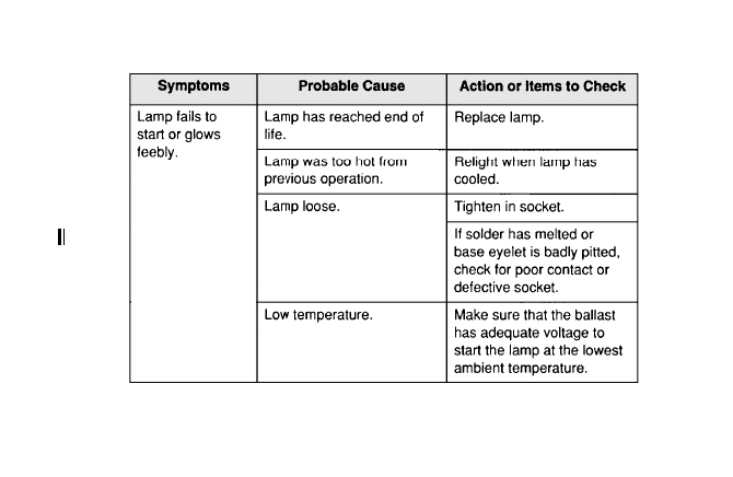
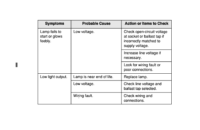
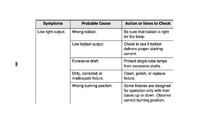
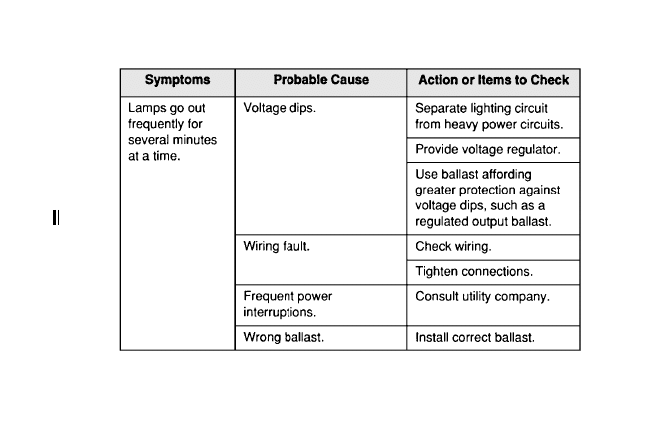
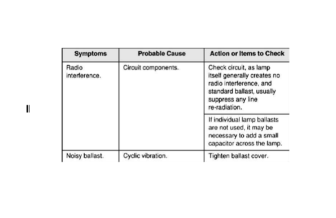
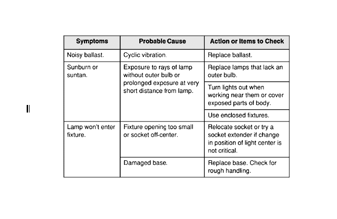
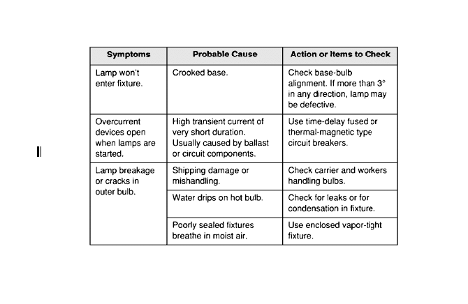
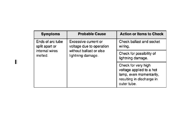
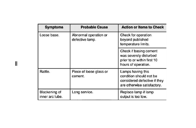
The troubleshooting chart in Figure 5-5 lists trou-
bleshooting techniques for HID luminaires.
76
77
5-4 Troubleshooting chart for incandescent luminaires.
78
5-4 Troubleshooting chart for incandescent luminaires. (Continued)
79
5-5 Troubleshooting chart for HID luminaires.
80
5-5 Troubleshooting chart for HID luminaires. (Continued)
81
5-5 Troubleshooting chart for HID luminaires. (Continued)
82
5-5 Troubleshooting chart for HID luminaires. (Continued)
83
5-5 Troubleshooting chart for HID luminaires. (Continued)
84
5-5 Troubleshooting chart for HID luminaires. (Continued)
85
5-5 Troubleshooting chart for HID luminaires. (Continued)
86
5-5 Troubleshooting chart for HID luminaires. (Continued)
87
5-5 Troubleshooting chart for HID luminaires. (Continued)
88
5-5 Troubleshooting chart for HID luminaires. (Continued)
89
5-5 Troubleshooting chart for HID luminaires. (Continued)

This page intentionally left blank

E
lectric motors operate on the principle of electro-
magnetic induction. An electric motor has a sta-
tionary magnet, or stator, with windings connected to
the supply conductors, and a rotating magnet. There
is no electrical connection between the stator and
rotor. The magnetic field produced in the stator wind-
ings induces a voltage in the rotor.
When an electric motor malfunctions, the stator
(stationary) windings are often defective, and must be
repaired or replaced. Stator problems are usually caused
by one or more of the following:
●
Worn bearings
●
Moisture
●
Overloading
●
Poor insulation
●
Single-phase operation of a three-phase
motor
91
Copyright © 2007, 2000, 1996 by The McGraw-Hill Companies, Inc.
Click here for terms of use.

Troubleshooting Motors
To detect defects in electric motors, the windings are
normally tested for ground faults, opens, shorts, and
reverses. The exact method of performing these tests
depends on the type of motor being serviced. However,
regardless of the motor type, a knowledge of some
important terms is necessary to properly troubleshoot
motors:
Ground: A winding becomes grounded when it
makes an electrical contact with the iron frame of
the motor. The usual causes of grounds include
bolts securing the end plates coming into contact
with the winding; wires press against laminations
at the corners of the slots; or the centrifugal
switch becoming grounded to the end plate.
Open circuits: Loose or dirty connections, as well
as a broken wire, can cause an open circuit in an
electric motor.
Shorts: If two or more turns of a winding contact
each other, the result is an electrical short circuit.
This condition may develop in a new winding if
the winding is tight and pounding is necessary to
place the wires in position. In other cases, exces-
sive heat caused by overloads degrades the insu-
lation and causes a short. A short circuit is often
detected by observing smoke from the windings
as the motor operates, or if the motor draws
excessive current at no load.
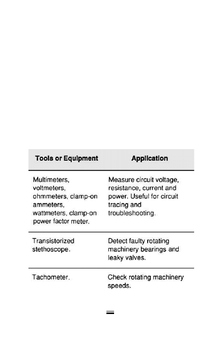
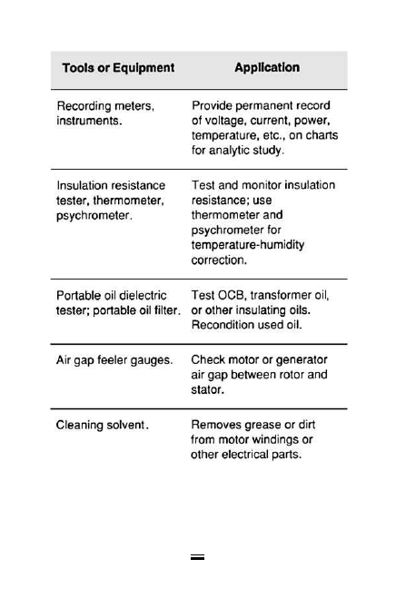
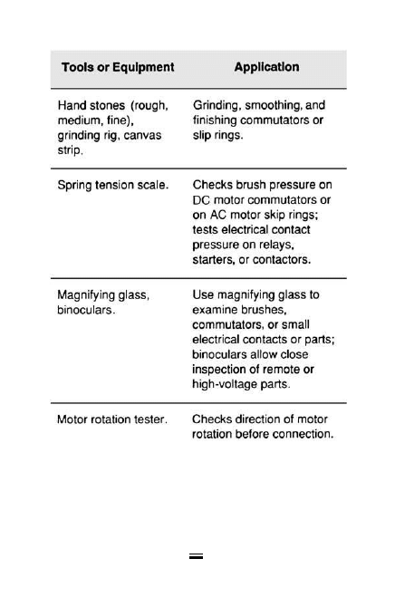
The chart in Figure 6-1 lists tools and equipment
used in maintenance and troubleshooting of electric
92
motors. The following sections describe common
causes of motor malfunctions.
Grounded Coils
A grounded coil in a motor winding typically causes
repeated tripping of the circuit breaker. Follow these
steps to test for a grounded coil using a continuity tester:
1. Open and lock out the disconnecting means,
to insure the motor is de-energized.
2. Place one test lead on the frame of the
motor and the other in turn on each of the
93
6-1 Tools for electric motor maintenance.
94
6-1 Tools for electric motor maintenance.
(Continued)
95
6-1 Tools for electric motor maintenance.
(Continued)

ungrounded (power) conductor supplying
the motor. If there is a grounded coil at any
point in the winding, the lamp of the conti-
nuity tester will light, or the meter display
will indicate infinity.
3. For a three-phase motor, test each phase sep-
arately, after disconnecting the star or delta
connection.
4. Sometimes moisture on old insulation around
the coils causes a high-resistance ground that
is difficult to detect with a test lamp. A megger
can be used to detect such faults.
5. Test the armature windings and commutator
for grounds in a similar manner.
6. On some motors, the brush holders are
grounded to the end plate. Before the arma-
ture is tested for grounds, lift the brushes
away from the commutator.
Shorted Coils
Shorted turns within coils are usually the result of failure
of the insulation on the wires, caused by oil, moisture,
and the like. One inexpensive way of locating a shorted
coil is by the use of a growler and a thin piece of steel,
as shown in Figure 6-2.
1. Place the growler in the core as shown, with
the thin piece of steel at the distance of one
coil span from the center of the growler.
96
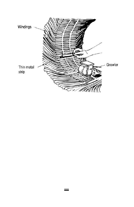
2. Test the coils by moving the growler around
the bore of the stator and always keeping the
steel strip the same distance away from it.
3. If any coil has one or more shorted turns, the
piece of steel will vibrate very rapidly and
cause a loud humming noise. By locating the
two slots over which the steel vibrates, both
sides of the shorted coil can be found.
4. Sometimes one coil or a complete coil group
becomes short-circuited at the end connec-
tions. The test for this fault is the same as that
for a shorted coil.
97
6-2 Growler used to test a stator of an AC motor.

Open Circuit
1. When one or more coils become open-circuited
by a break in the turns or a poor connection at
the end, they can be tested with a continuity
tester as previously explained. If this test is
made at the ends of each winding, an open can
be detected by the lamp failing to light. Remove
the insulation from the pole-group connec-
tions, and test each group separately.
2. An open circuit in the starting winding may
be difficult to locate, since the problem may
be in the centrifugal switch instead of the
winding itself. In fact, the centrifugal switch is
more likely to cause trouble than the winding
since parts become worn, defective, and more
likely, dirty. Insufficient pressure of the rotat-
ing part of centrifugal switches against the sta-
tionary part will prevent the contacts from
closing and thereby produce an open circuit.
Reversed Coil Connections
Reversed connections cause current to flow through
coils in the wrong direction. This causes disturbance
of the magnetic circuit, which results in excessive
noise and vibration.
The fault can be located by the use of a magnetic
compass and a direct current power source, as follows:
1. Adjust to send about one-fourth to one-sixth
of the full-load current through the winding,
98

with the DC leads placed on the start and
finish of one phase.
2. If the winding is a three-phase, star-connected,
winding this is at the start of one phase and
the star point. If the winding is delta-connected,
disconnect the delta point and test each phase
separately.
3. Place a compass on the inside of the stator
and test each coil group in that phase. If the
phase is connected correctly, the needle of
the compass will reverse definitely as it is
moved from one coil group to another.
However, if any one of the coils is reversed,
the reversed coil will build up a field in the
direction opposite to the others, thus causing
a neutralizing effect that is indicated by the
compass needle refusing to point definitely to
that group. If there are only two coils per
group, there will be no indication if one of
them is reversed, as that group will be com-
pletely neutralized.
4. When an entire coil group is reversed, current
flows in the wrong direction in that whole
group. The test for this fault is the same as
that for reversed coils. Magnetize the winding
with DC, and when the compass needle is
passed around the coil group, it should alter-
nately indicate North-South, North-South,
and so on.
99

Reversed Phase
Sometimes in a three-phase winding a complete phase
is reversed by either having taken the starts from the
wrong coils or connecting one of the windings in the
wrong relation to the others when making the star or
delta connections.
Delta connection: In a delta-connected winding,
disconnect any one of the points where the phases
are connected together and pass current through the
three windings in series. Place a compass on the
inside of the stator and test each coil group by slowly
moving the compass one complete revolution
around the stator. The reversals of the needle in mov-
ing the compass one revolution around the stator
should be three times the number of poles in the
winding.
Wye connection: In a star- or wye-connected wind-
ing, connect the three starts together and place them
on one DC lead. Then connect the other DC lead
and star point, thus passing the current through all
three windings in parallel. Test with a compass in the
same way as the delta winding. The result should
then be the same, or the reversals of the needle in
making one revolution around the stator should
again be three times the number of poles in the
winding.
These tests for reversed phases apply to full-pitch
windings only. If the winding is fractional-pitch, a
careful visual check should be made to determine
whether there is a reversed phase or mistake in con-
necting the star or delta connections.
100

Troubleshooting Split-Phase Motors
If a split-phase motor fails to start, the trouble may be
due to one or more of the following faults:
●
Tight or “frozen” bearings
●
Worn bearings, allowing the rotor to
drag on the stator
●
Bent rotor shaft
●
One or both bearings out of alignment
●
Open circuit in either starting or running
windings
●
Defective centrifugal switch
●
Improper connections in either winding
●
Grounds in either winding or both
●
Shorts between the two windings
Tight or worn bearings: Tight or worn bearings may
be due to the lubricating system failing, or when new
bearings are installed, they may run hot if the shaft is
not kept well oiled. If the bearings are worn to such
an extent that they allow the rotor to drag on the sta-
tor, this will usually prevent the rotor from starting.
The inside of the stator laminations will be worn
bright where they are rubbed by the rotor. When this
condition exists, it can generally be easily detected by
close observation of the stator field and rotor surface
when the rotor is removed.
Bent shaft and bearings out of alignment: A bent rotor
shaft will usually cause the rotor to bind in a certain
position but then run freely until it comes back to the
same position again. Test for a bent shaft by placing the
rotor between centers on a lathe and turning the rotor
101

slowly while a tool or marker is held in the tool post
close to the surface of the rotor. If the rotor wobbles, it
is an indication of a bent shaft. Bearings out of align-
ment are usually caused by uneven tightening of the
end-shield plates. When placing end shields or brack-
ets on a motor, tighten the bolts alternately, first draw-
ing up two bolts, which are diametrically opposite.
Open circuits and defective centrifugal switches: Open
circuits in either the starting or running winding will
prevent the motor from starting. This fault can be
detected by testing in series with the start and finish
of each winding with a test lamp or ohmmeter.
A defective centrifugal switch is generally caused
by dirt, grit, or some other foreign matter getting into
the switch. The switch should be thoroughly cleaned
with a degreasing solution and then inspected for
weak or broken springs.
If the winding is on the rotor, the brushes some-
times stick in the holders and fail to make good con-
tact with the slip rings. This causes sparking at the
brushes. There will probably also be a certain place
where the rotor will not start until it is moved far
enough for the brush to make contact on the ring.
The brush holders should be cleaned and the brushes
carefully fitted so they move more freely with a min-
imum of friction between the brush and the holders.
Reversed connections and grounds: Reversed connec-
tions are caused by improperly connecting a coil or
group of coils. The wrong connections can be found
and corrected by making a careful check on the con-
nections and reconnecting those that are found at
102

fault. The compass test with a DC power source can
also be used for locating reversed coils. Test the start-
ing and running windings separately, exciting only
one winding at a time, with direct current. The com-
pass should show alternate poles around the winding.
The operation of a motor that has a ground in the
winding will depend on where the ground is and
whether or not the frame is grounded. If the frame is
grounded, then when the ground occurs in the wind-
ing, it will usually blow a fuse or trip the overcurrent
protective device.
A test for grounds can be made with a test lamp or
continuity tester. One test lead should be placed on
the frame and the other on a lead to the winding. If
there is no ground, the lamp will not light, nor will
any deflection be present when a meter is used. If the
lamp does light or the meter shows continuity, it indi-
cates a ground is present—due to a defect somewhere
in the motor’s insulation.
Short circuits: Short circuits between any two wind-
ings can be detected by the use of a test lamp or con-
tinuity tester. Place one of the test leads on one wire
of the starting winding and the other test lead on the
wire of the running winding. If these windings are
properly insulated from each other, the lamp should
not light.
If it does, it is a certain indication that a short or
ground fault exists between the windings. Such a con-
dition will usually cause part of the starting winding
to burn out. The starting winding is always wound on
top of the running winding, so a defective starting
103

winding can be conveniently removed and replaced
without disturbing the running winding.
Identifying Motors
Electric motors with no identification (no nameplate
or lead tags) must often be maintained and repaired.
Follow these steps to determine an unknown motor’s
characteristics, based on the NEMA Standard method
of motor identification. First, sketch the coils to form
a wye. Identify one outside coil end with the number
one (1), and then draw a decreasing spiral and num-
ber each coil end in sequence as shown in Figure 6-3.
Using a DMM, ohmmeter, or continuity tester, the
individual circuits can then be identified as follows:
Step 1. Connect one probe of the tester to any
lead, and check for continuity to each of
the other eight leads. A reading from
only one other lead indicates one of the
two-wire circuits. A reading to two other
leads indicates the three-wire circuit that
makes up the internal wye connection.
Step 2. Continue checking and isolating leads
until all four circuits have been located.
Tag the wires of the three lead circuits T-7, T-8,
and T-9 in any order. The other leads should be
temporarily marked T-1 and T-4 for one circuit,
T-2 and T-5 for the second circuit, and T-3 and
T-6 for the third and final circuit.
The following test voltages are for the most
common dual-voltage range of 230/460 V. For
104
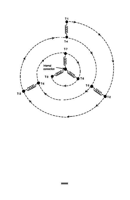
other motor ranges, the voltages listed should be
changed in proportion to the motor rating.
As all the coils are physically mounted in slots
on the same motor frame, the coils will act
almost like the primary and secondary coils of a
transformer. Figure 6-4 shows a simplified
electrical arrangement of the coils. Depending
on which coil group power is applied to, the
105
6-3 Identify one outside coil and then draw a
decreasing spiral and number each coil.
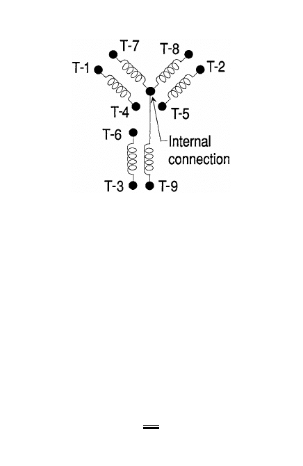
resulting voltage readings will be additive, subtrac-
tive, balanced, or unbalanced depending on phys-
ical location with regard to the coils themselves.
Step 3. The motor may be started on 230 V by
connecting leads T-7, T-8, and T-9 to the
three-phase source. If the motor is too
large to be connected directly to the line,
the voltage should be reduced by using a
reduced voltage starter or other suitable
means.
Step 4. Start the motor with no load connected
and bring up to normal speed.
Step 5. With the motor running, a voltage will
be induced in each of the open two-wire
106
6-4 Simplified electrical arrangement of wye-wound
motor coils.

107
circuits that were tagged T-1 and T-4, T-
2 and T-5, and T-3 and T-6. With a volt-
meter, check the voltage reading of
each circuit. The voltage should be
approximately 125 to 130 V and should
be the same on each circuit.
Step 6. With the motor still running, carefully
connect the lead that was temporarily
marked T-4 with the T-7 and line lead.
Read the voltage between T-1 and T-8 and also
between T-1 and T-9. If both readings are of the
same value and are approximately 330 to 340 V,
leads T-1 and T-4 may be disconnected and per-
manently marked T-1 and T-4.
Step 7. If the two voltage readings are of the
same value and are approximately 125
to 130 V, disconnect and interchange
leads. If the test calls for equal voltages
of 125 to130 V and the reading is only
80 to 90 V, this is acceptable as long as
the voltage readings are nearly equal. T-
1 and T-4 and mark permanently (orig-
inal T-1 changed to T-4 and original T-4
changed to T-1).
Note
The voltages referred to during the testing are
only for reference and will vary greatly from
motor to motor, depending on size, design, and
manufacturer.

Step 8. If readings between T-1 and T-8 and
between T-1 and T-9 are of unequal val-
ues, disconnect T-4 from T-7 and recon-
nect T-4 to the junction of T-8 and line.
Step 9. Measure the voltage now between T-1
and T-7 and also between T-1 and T-9. If
the voltages are equal and approxi-
mately 330 to 340 V, tag T-1 is perma-
nently marked T-2 and T-4 is marked
T-5 and disconnected. If the readings
taken are equal but are approximately
125 to 130 V, leads T-1 and T-4 are dis-
connected, interchanged, and marked
T-2 and T-5 (T-1 changed to T-5, and T-
4 changed to T-2). If both voltage read-
ings are different, T-4 lead is
disconnected from T-8 and moved to T-
9. Voltage readings are taken again
(between T-1 and T-7 and T-1 and T-8)
and the leads permanently marked T-3
and T-6 when equal readings of approx-
imately 330 to 340 V are obtained.
Step 10. Follow the same procedure for the
other two circuits that were temporar-
ily marked T-2 and T-5 and T-3 and T-6,
until a position is found where both
voltage readings are equal and approx-
imately 330 to 340 V and the tags
change to correspond to the standard
lead markings as shown in Figure 6-5.
108
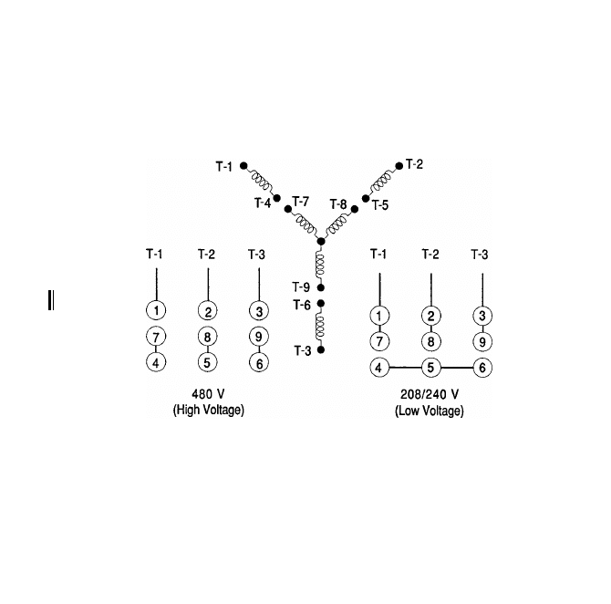
109
6-5 NEMA Standard lead markings for dual-voltage,
wye-wound motors.

Step 11. Once all leads have been properly and
permanently tagged, leads T-4, T-5, and
T-6 are connected together and voltage
readings are taken between T-1, T-2,
and T-3. The voltages should be equal
and approximately 230 V.
Step 12. As an additional check, the motor is
shut down and leads T-7, T-8, and T-9
are disconnected, and leads T-1, T-2,
and T-3 are connected to the line.
Connect T-1 to the line lead T-7 was con-
nected to, T-2 to the same line as T-8 was previ-
ously connected to, and T-3 to the same lead
that T-9 was connected to. With T-4, T-5, and
T-6 still connected together to form a wye con-
nection, the motor can again be started without
a load. If all lead markings are correct, the motor
rotation with leads T-1, T-2, and T-3 connected
will be the same as when T-7, T-8, and T-9 were
connected.
The motor is now ready for service and is con-
nected in series for high voltage or parallel for low as
indicated by the NEMA Standard connections shown
in Figure 6-6.
Three-Phase Delta-Wound Motors
Most dual-voltage, delta-wound motors also have
nine leads, as indicated in Figure 6-6, but there are
only three circuits of three leads each. Use continuity
tests to find the three coil groups, as was done for the
110
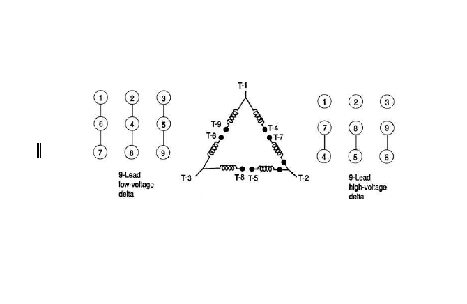
111
6-6 NEMA Standard lead markings for dual-voltage, delta-wound
motors.

112
wye-wound motor. Once the coil groups are located
and isolated, make further resistance checks to
locate the common wire in each coil group. A DMM,
Wheatstone bridge, or other sensitive device may be
needed, since the resistance of some delta-wound
motors is very low.
Each coil group consists of two coils tied together
with three leads brought out to the motor junction or
terminal box. Reading the resistance carefully
between each of the three leads shows that the read-
ings from one of the leads to each of the other two
leads will be the same (equal), but the resistance read-
ing between those two leads will be double the previ-
ous readings; Figure 6-7 illustrates the technique:
Step 1. The common lead found in the first coil
group is permanently marked T-1, and
the other two leads temporarily marked
T-4 and T-9. The common lead of the
next coil group is found and perma-
nently marked T-2 and the other leads
temporarily marked T-5 and T-7. The
common lead of the last coil group is
located and marked T-3 with the other
leads being temporarily marked T-6 and
T-8.
Note
This procedure may not work on some wye-
connected motors with concentric coils.

Step 2. After the leads have been marked, con-
nect the motor to a 230-V three-phase
line using leads T-1, T-4, and T-9. Lead
T-7 is connected to line and T-4, and the
motor is started with no load connected.
Voltage readings are taken between T-1
and T-2. If the voltage is approximately
460 V, the markings are correct and may
be permanently marked.
Step 3. If the voltage reading is 400 V or less,
interchange T-5 and T-7 or T-4 and T-9
and read the voltage again. If the voltage
is approximately 230 V, interchange both
T-5 with T-7 and T-4 with T-9. The read-
ings should now be approximately 460 V
between leads T-1 and T-2. The leads
connected together now are actually T-4
and T-7 and are marked permanently.
The remaining lead in each group can
now be marked T-9 and T-5, as indicated
by Figure 6-7.
Step 4. Connect one of the leads of the last coil
group (not T-3) to T-9. If the reading is
approximately 460 V between T-1 and T-3,
permanently mark this lead T-6. If the
reading is 400 V or less, interchange T-6
and T-8. A reading now of 460 V should
exist between T-1 and T-3. T-6 is changed
to T-8 and marked permanently and
temporary T-8 is changed to T-6.
113
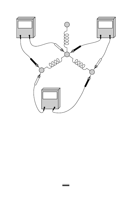
If all leads are now correctly marked, equal
readings of approximately 460 V can be obtained
between leads T-1, T-2, and T-3.
Step 5. To double-check these markings, shut off
the motor and reconnect it using T-2, T-5,
and T-7. Connect T-2 to the same line
lead as T-1, connect T-5 where T-4 was,
and connect T-7 where T-9 was previously
114
Ohm
1.0
Ohm
0.5
Ohm
0.5
A
B
C
6-7 Using DMM to test motor leads.

connected. When started, the motor
should rotate the same direction as before.
Step 6. Stop the motor and connect leads T-3, T-6,
and T-8 to the line leads previously
connected to T-2, T-5, and T-7, respec-
tively, and when the motor is started it
should still rotate in the same direction.
The motor is now ready for service and is
connected in series for high or parallel for
low voltage as indicated by the NEMA
Standard connections shown in Figure 6-6.
Record Keeping
Accurate records are an important element of an effec-
tive motor maintenance program. Records on each
motor should include the following, at a minimum:
●
Complete description, including age and
nameplate data.
●
Location and application, updates when
motors are transferred to different areas
or used for different purposes.
●
Notations of scheduled preventive mainte-
nance and previous repair work performed.
●
Location of duplicate or interchangeable
motors.
Troubleshooting Charts
The troubleshooting chart (Figure 6-8) lists common
motor problems along with their causes and remedies.
115
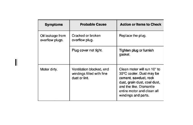
116
6-8 Troubleshooting chart for electric motors.
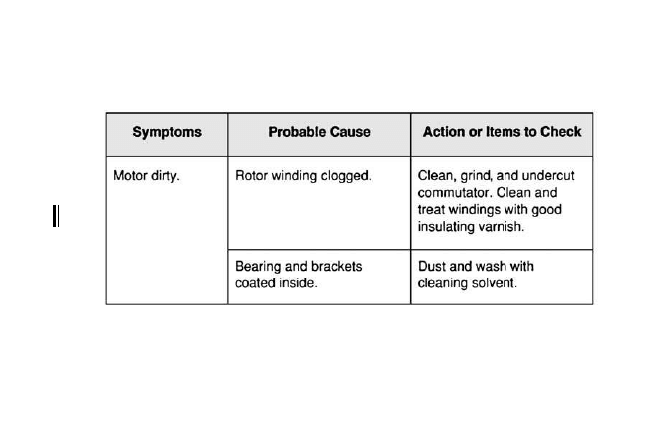
117
6-8 Troubleshooting chart for electric motors. (Continued)
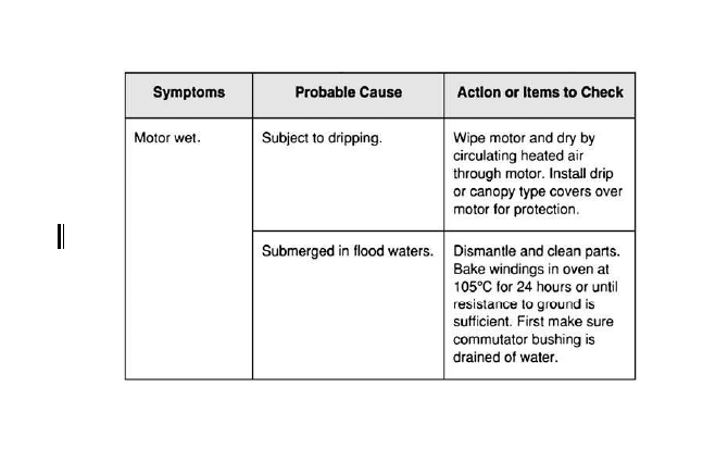
118
6-8 Troubleshooting chart for electric motors. (Continued)
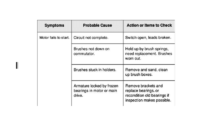
119
6-8 Troubleshooting chart for electric motors. (Continued)
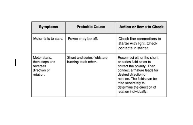
120
6-8 Troubleshooting chart for electric motors. (Continued)
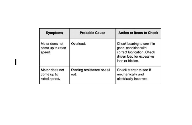
121
6-8 Troubleshooting chart for electric motors. (Continued)
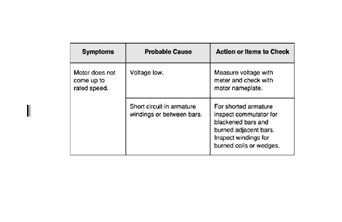
122
6-8 Troubleshooting chart for electric motors. (Continued)
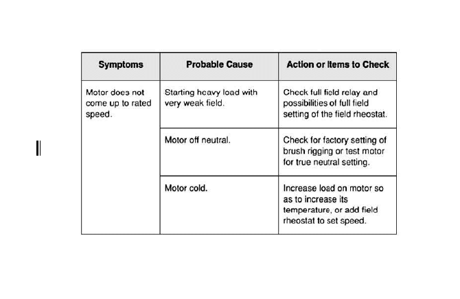
123
6-8 Troubleshooting chart for electric motors. (Continued)
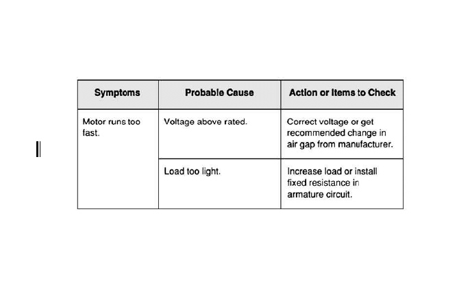
124
6-8 Troubleshooting chart for electric motors. (Continued)
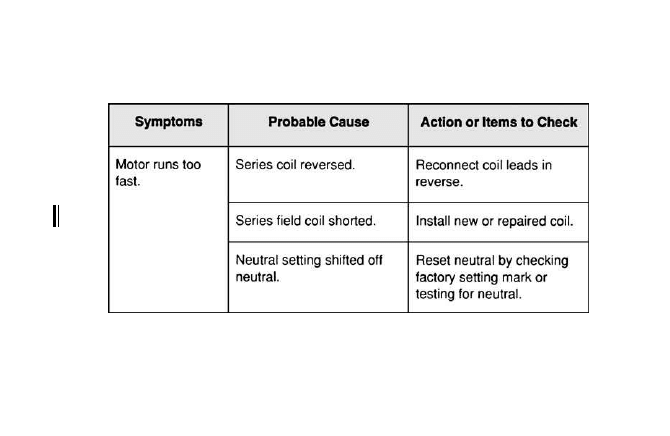
125
6-8 Troubleshooting chart for electric motors. (Continued)
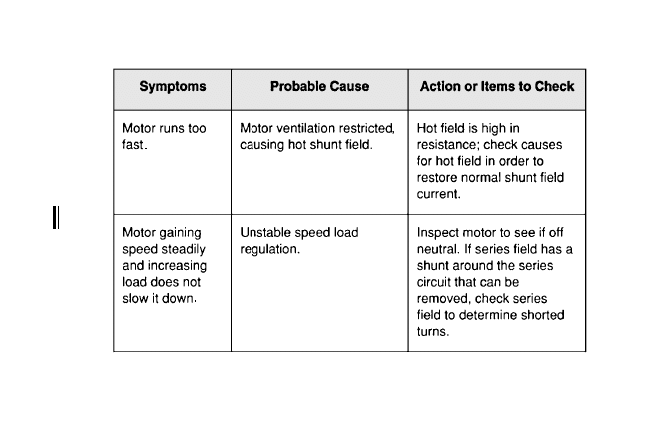
126
6-8 Troubleshooting chart for electric motors. (Continued)
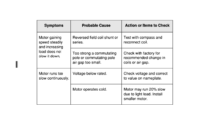
127
6-8 Troubleshooting chart for electric motors. (Continued)
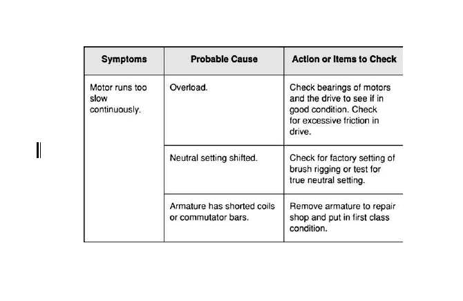
128
6-8 Troubleshooting chart for electric motors. (Continued)
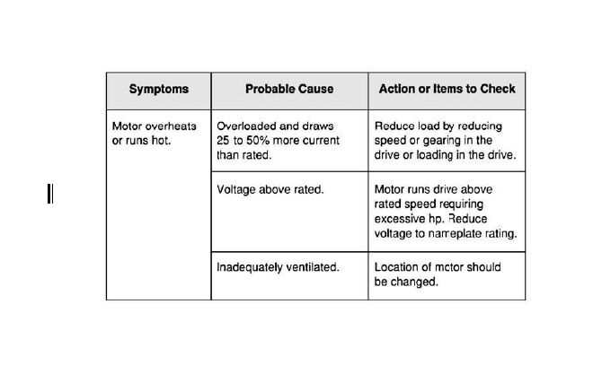
129
6-8 Troubleshooting chart for electric motors. (Continued)
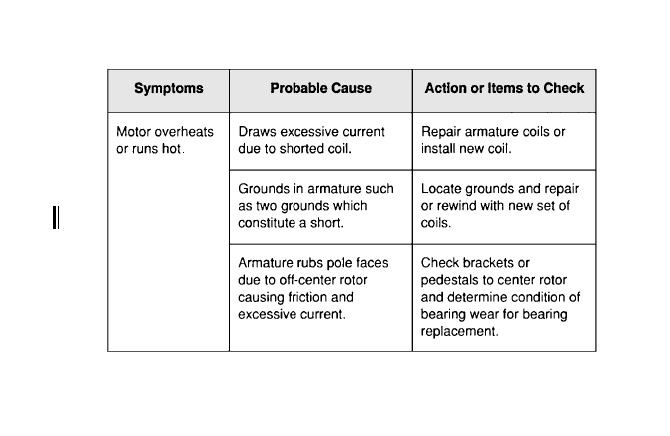
130
6-8 Troubleshooting chart for electric motors. (Continued)
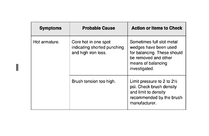
131
6-8 Troubleshooting chart for electric motors. (Continued)
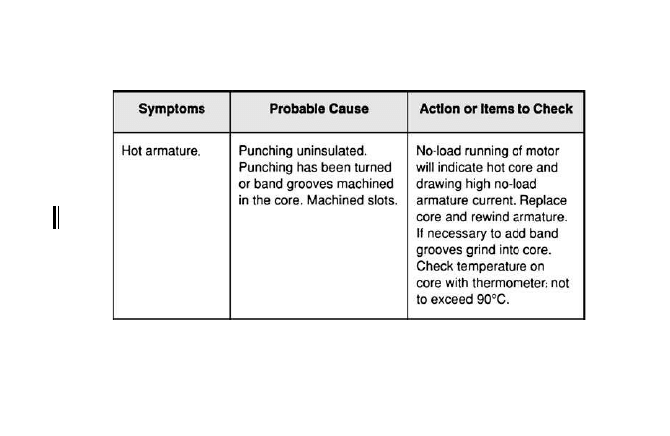
132
6-8 Troubleshooting chart for electric motors. (Continued)
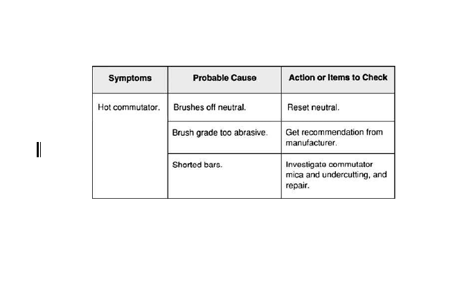
133
6-8 Troubleshooting chart for electric motors. (Continued)
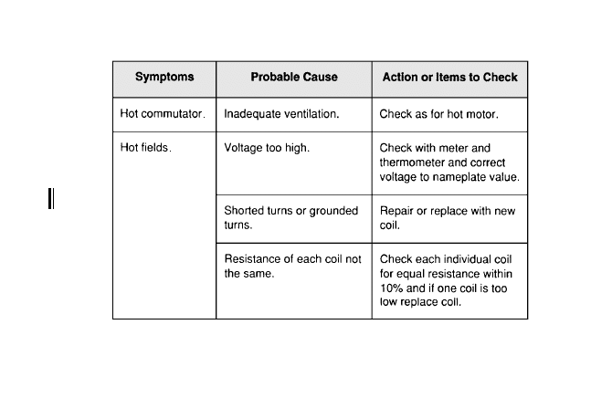
134
6-8 Troubleshooting chart for electric motors. (Continued)
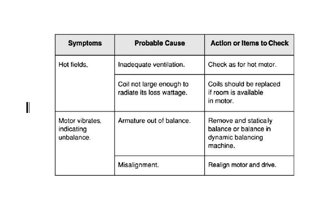
135
6-8 Troubleshooting chart for electric motors. (Continued)
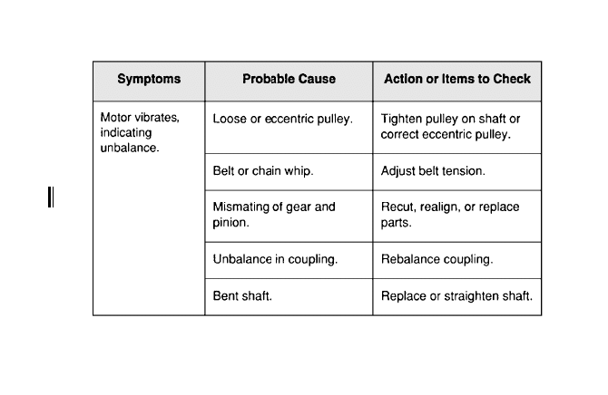
136
6-8 Troubleshooting chart for electric motors. (Continued)
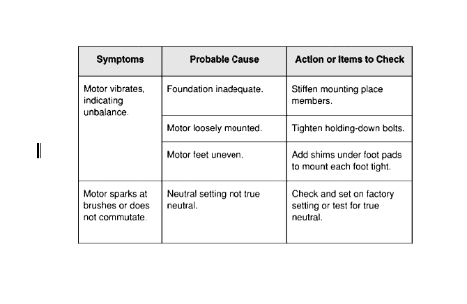
137
6-8 Troubleshooting chart for electric motors. (Continued)
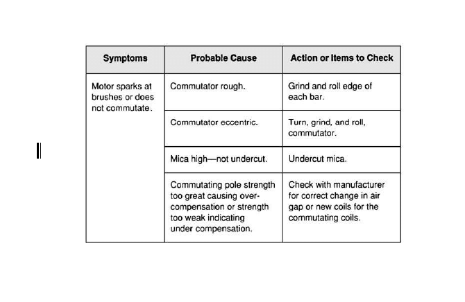
138
6-8 Troubleshooting chart for electric motors. (Continued)
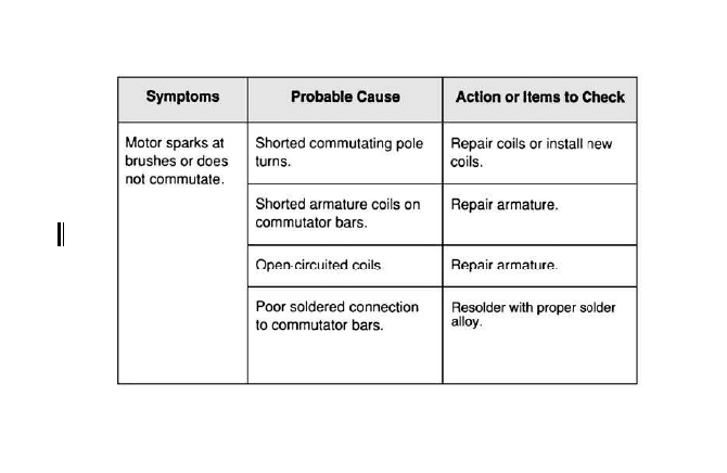
139
6-8 Troubleshooting chart for electric motors. (Continued)
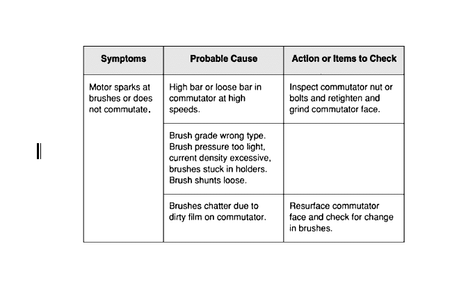
140
Inspect brushes and
replace as necessary.
Inspect brushes and
replace as necessary.
6-8 Troubleshooting chart for electric motors. (Continued)
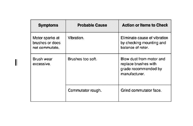
141
6-8 Troubleshooting chart for electric motors. (Continued)
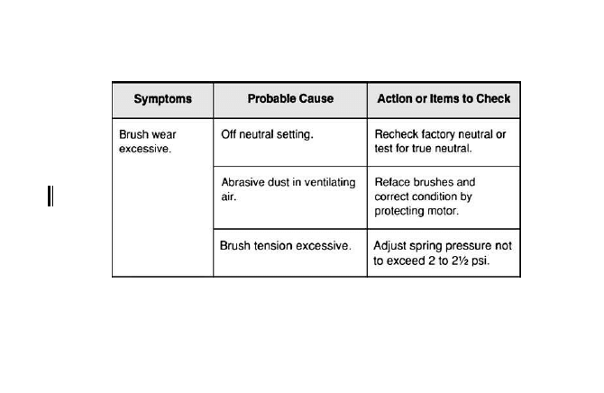
142
6-8 Troubleshooting chart for electric motors. (Continued)
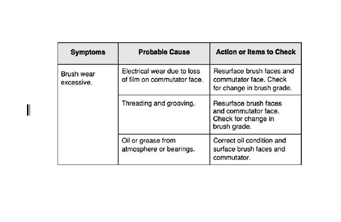
143
6-8 Troubleshooting chart for electric motors. (Continued)
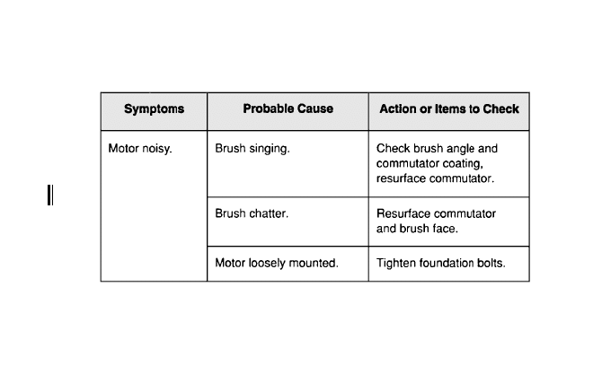
144
6-8 Troubleshooting chart for electric motors. (Continued)
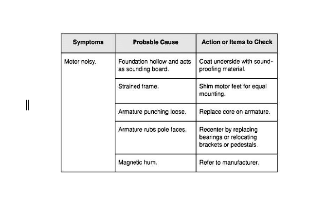
145
6-8 Troubleshooting chart for electric motors. (Continued)
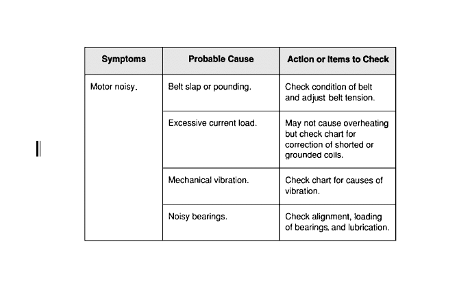
146
6-8 Troubleshooting chart for electric motors. (Continued)
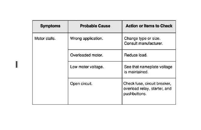
147
6-8 Troubleshooting chart for electric motors. (Continued)
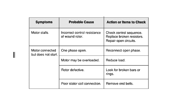
148
6-8 Troubleshooting chart for electric motors. (Continued)
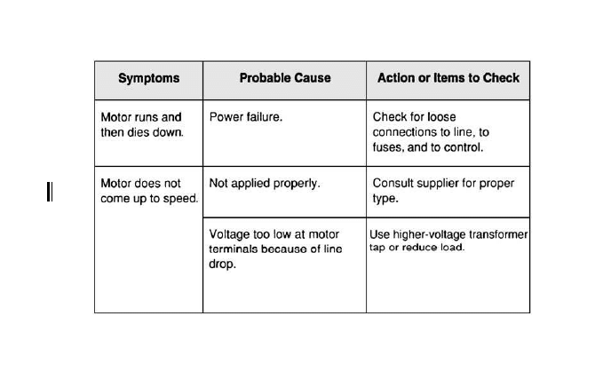
149
6-8 Troubleshooting chart for electric motors. (Continued)
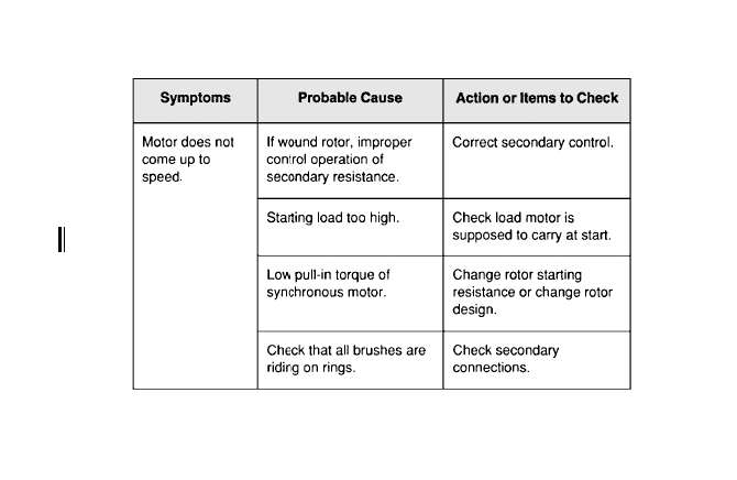
150
6-8 Troubleshooting chart for electric motors. (Continued)
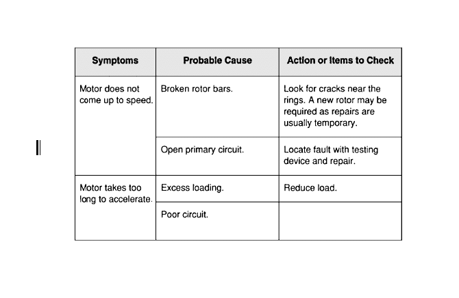
151
6-8 Troubleshooting chart for electric motors. (Continued)
Check for excessive
voltage drop.
Check for excessive
voltage drop.
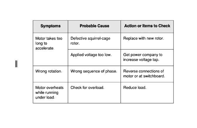
152
6-8 Troubleshooting chart for electric motors. (Continued)
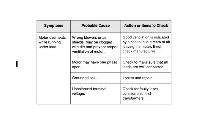
153
6-8 Troubleshooting chart for electric motors. (Continued)
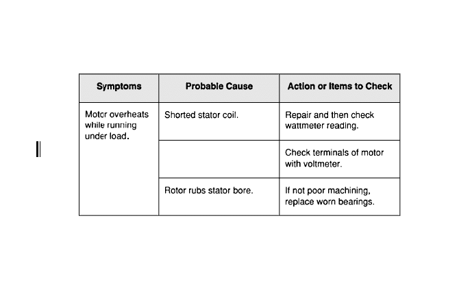
154
Voltage too high or low.
Voltage too high or low.
6-8 Troubleshooting chart for electric motors. (Continued)
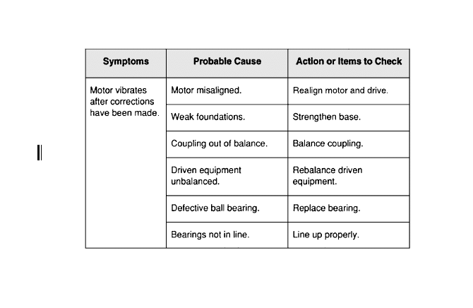
155
6-8 Troubleshooting chart for electric motors. (Continued)
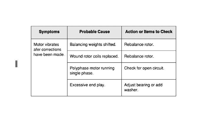
156
6-8 Troubleshooting chart for electric motors. (Continued)
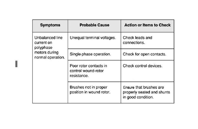
157
6-8 Troubleshooting chart for electric motors. (Continued)
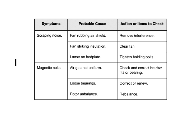
158
6-8 Troubleshooting chart for electric motors. (Continued)

A
lternating-current motors account for a high per-
centage of electrical repair work. A high propor-
tion of failures are caused by faulty bearings. Sleeve
and ball bearing failure can occur in both newer and
older motors; but sealed motor bearings are much less
prone to failure.
Types of Bearings
There are many types of motor bearings, with ball
bearings being the most common. There are several
different types of ball bearings used in motors:
●
Open
●
Single shielded
●
Double shielded
●
Sealed
●
Double row and other special types
Open bearings, as the name implies, are open
construction and must be installed in a sealed
housing. These bearings are less apt to cause
159
Copyright © 2007, 2000, 1996 by The McGraw-Hill Companies, Inc.
Click here for terms of use.

churning of grease, and for this reason are used
mostly on large motors.
Single-shielded bearings have a shield on one side
to exclude grease from the motor windings.
Double-shielded bearings have a shield on both
sides of the bearing. This type of bearing is less
susceptible to contamination, requires no main-
tenance, and does not require regreasing. It is
normally used on small- or medium-size motors.
Each bearing type has characteristics which make it
the best choice for a certain application. Replacement
should be made with the same type bearings. The fol-
lowing list of functions provide a basic understanding
of bearing application, a guide to analysis of bearing
troubles due to misapplication, and emphasize the
importance of proper replacement.
Figure 7-1 shows several types of bearings used in
electric motors. The following is a brief description of
each:
Self-aligning ball bearings: Self-aligning ball bearings
are used for radial loads and moderate thrust loads in
either direction. This ball bearing, has two rows of
balls rolling on the spherical surface of the outer ring,
compensates for angular misalignment resulting from
errors in mounting, shaft deflection, and distortion of
the foundation. It is impossible for this bearing to
exert any bending influence on the shaft—an important
consideration in high-speed applications requiring
extreme accuracy.
160
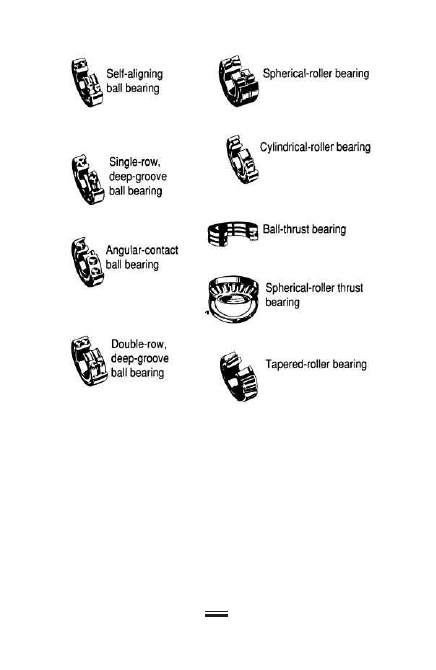
Single-row, deep-groove ball bearings: The single-row,
deep-groove ball bearing will sustain, in addition to
radial load, a substantial thrust load in either direc-
tion, even at very high speeds. This advantage results
from the intimate contact existing between the balls
and the deep, continuous groove in each ring. When
using this type of bearing, careful alignment between
161
7-1 Various bearing types.

the shaft and housing is essential. This bearing is also
available with seals and shields, which exclude dirt
and retain lubricant.
Angular-contact ball bearings: The angular-contact
ball bearing supports a heavy thrust load in one
direction, sometimes combined with a moderate radial
load. A steep contact angle, assuring the highest
thrust capacity and axial rigidity, is obtained by a high
thrust-supporting shoulder on the inner ring and a
similar high shoulder on the opposite side of the
outer ring.
Double-row, deep-groove ball bearings: The double-row,
deep-groove ball bearing has a lower axial displace-
ment than the single-row design, substantial thrust
capacity in either direction, and high radial capacity
due to the two rows of balls.
Spherical-roller bearings: The spherical-roller bearing
has maximum capacity, due to the number, size, and
shape of the rollers, and the accuracy with which they
are guided. Since the bearing is inherently self-aligning,
angular misalignment between the shaft and housing
has no detrimental effect, and the full capacity is always
available for useful work.
Cylindrical-roller bearings: This type of bearing has
high radial capacity and provides accurate guiding of
the rollers, resulting in low friction that permits oper-
ation at high speed. The double-row type is particu-
larly suitable for machine-tool spindles.
Ball-thrust bearings: The ball-thrust bearing is
designed for thrust load in one direction only. The load
line through the balls is parallel to the axis of the shaft,
162

resulting in high-thrust capacity and minimum-axial
deflection.
Spherical-roller thrust bearings: The spherical-roller
thrust bearing is designed to carry heavy thrust loads,
or combined loads, which are predominantly thrust.
This bearing has a single row of rollers that roll on a
spherical outer race with full self-alignment. The cage,
centered by an inner ring sleeve, is constructed so that
lubricant is pumped directly against the inner ring’s
unusually high guide flange.
Tapered-roller bearings: Since the axes of its rollers
and raceways form an angle with the shaft axis, the
tapered-roller bearing is especially suitable for carry-
ing radial and axial loads acting simultaneously. A
bearing of this type usually must be adjusted toward
another bearing capable of carrying thrust loads in
the opposite direction. Tapered-roller bearings are
separable; their cones (inner rings) with rollers and
their cups (outer rings) are mounted separately.
The do’s and don’ts for ball-bearing assembly,
maintenance, inspection, and lubrication are shown
in Figure 7-2.
Frequency of Lubrication
Frequency of motor lubrication depends not only on
the type of bearing but also on the motor application.
Small- and medium-size motors equipped with ball
bearings (except sealed bearings) are greased every 3 to
6 years if the motor duty is normal. Severe applications
(high temperature, wet or dirty locations, or corrosive
atmospheres), may require more frequent lubrication.
163

164
7-2 Do’s and don’ts for ball-bearing assembly,
maintenance, and lubrication.

165
7-2 Do’s and don’ts for ball-bearing assembly,
maintenance, and lubrication. (Continued)
(Cont.)
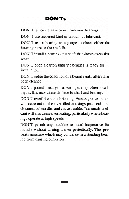
166
7-2 Do’s and don’ts for ball-bearing assembly,
maintenance, and lubrication. (Continued)
(Cont.)

Lubrication in sleeve bearings should be changed
at least once a year. When the motor duty is severe
or the oil appears dirty, it should be changed more
frequently.
Lubrication Procedure
Cleanliness and using the proper lubricant are criti-
cally important when lubricating motors. Follow this
procedure:
1. Wipe the bearing housing, grease gun, and
fittings clean.
2. Take care to keep dirt out of the bearing when
greasing.
3. Next, remove the relief plug from the bottom
of the bearing housing. This prevents exces-
sive pressure from building up inside the
bearing housing during greasing.
4. Add grease, with the motor running if possi-
ble, until it begins to flow from the relief
hole. Let the motor run 5 to 10 minutes to
expel excess grease. Replace the relief plug
and clean the bearing housing.
5. Avoid over-greasing. When too much grease
is forced into a bearing, churning of the lubri-
cant occurs, resulting in high temperature
and eventual bearing failure.
6. On motors that don’t have relief holes, apply
grease sparingly. If possible, disassemble the
167

motor and repack the bearing housing with
the proper amount of grease. During this pro-
cedure, always maintain strict cleanliness.
Testing Bearings
Two of the most effective tests are what might be
called the “feel” test and the “sound” test. Perform the
“feel” test while the motor is running; if the bearing
housing feels overly hot to the touch, it is probably
malfunctioning.
During the “sound” test, listen for foreign noises
coming from the motor. Also, one end of a steel rod
(about 3 ft long and 1.2 in. in diameter) may be
placed on the bearing housing while the other end is
held against the ear. The rod then acts as an amplifier,
transmitting unusual sounds such as thumping or
grinding, which indicate a failing bearing. Special lis-
tening devices, such as a transistorized stethoscope,
can also be used for the purpose.
The troubleshooting chart in Figure 7-3 lists the
most common problems with motor bearings.
168
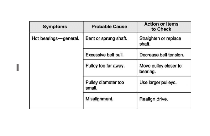
169
7-3 Troubleshooting chart for motor bearings.
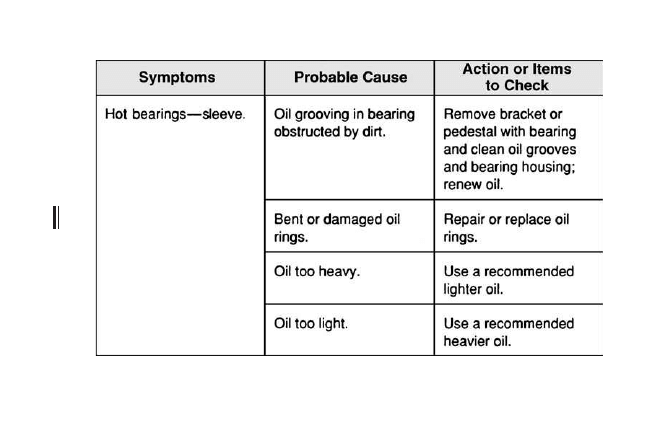
170
7-3 Troubleshooting chart for motor bearings. (Continued)

171
Symptoms
Probable Cause
Action or Items
to Check
Insufficient oil.
Hot bearings—sleeve.
Too much end thrust.
Badly worn bearing.
Replace bearing.
Fill reservoir to proper
level in overflow plug
with motor at rest.
Reduce thrust induced
by driven machine or
supply external means
to carry thrust.
7-3 Troubleshooting chart for motor bearings. (Continued)
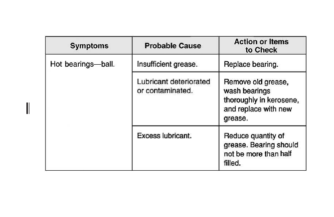
172
7-3 Troubleshooting chart for motor bearings. (Continued)
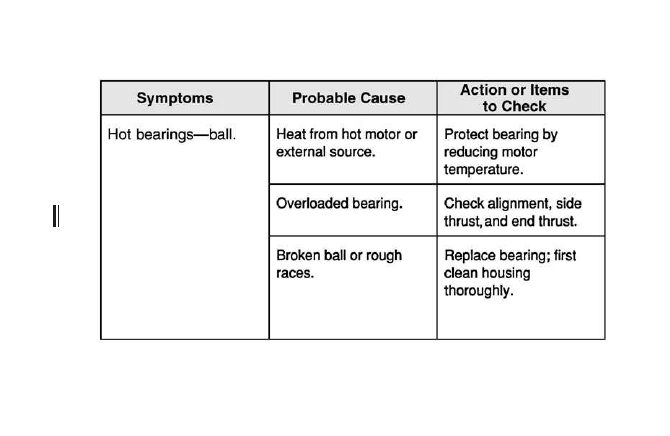
173
7-3 Troubleshooting chart for motor bearings. (Continued)

This page intentionally left blank

A
relay is an electromagnetic or solid-state device
used in control circuits of magnetic motor starters,
heaters, solenoids, timers, and other devices. They are
frequently used for remote control applications. Relays
are manufactured in a number of different configu-
rations, in both mechanical and solid-state designs.
Figure 8-1 shows a type of relay often used to control
small, single-phase motors and other light loads such
as heaters or pilot lights.
Contactors are electromagnetic devices similar in
construction and operation to relays, but designed to
handle much higher currents (Figure 8-2) involved in
applications such as switching large banks of stadium
lights on and off.
Figure 8-3 describes troubleshooting procedures for
relays and contactors.
175
Copyright © 2007, 2000, 1996 by The McGraw-Hill Companies, Inc.
Click here for terms of use.
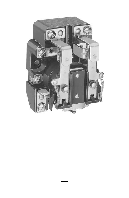
176
8-1 Single-pole, single-throw (SPST) relay rated
30 A, 600 V. (Courtesy of Schneider Electric Company.)
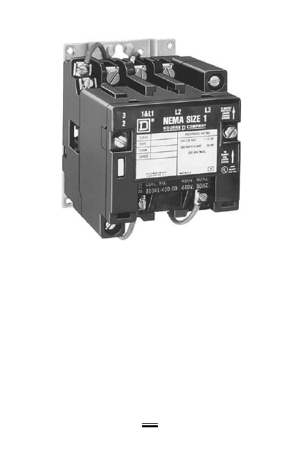
177
8-2 NEMA size 1 contactor rated 10HP, 575 V.
(Courtesy of Schneider Electric Company.)
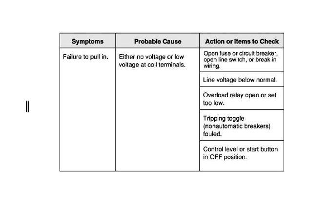
178
8-3 Contactor and relay troubleshooting chart.
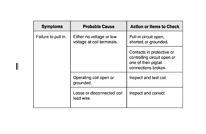
179
8-3 Contactor and relay troubleshooting chart. (Continued)
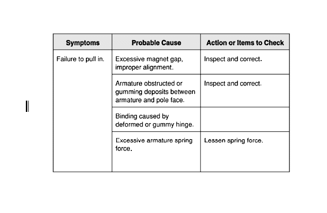
180
Replace or degrease.
8-3 Contactor and relay troubleshooting chart. (Continued)
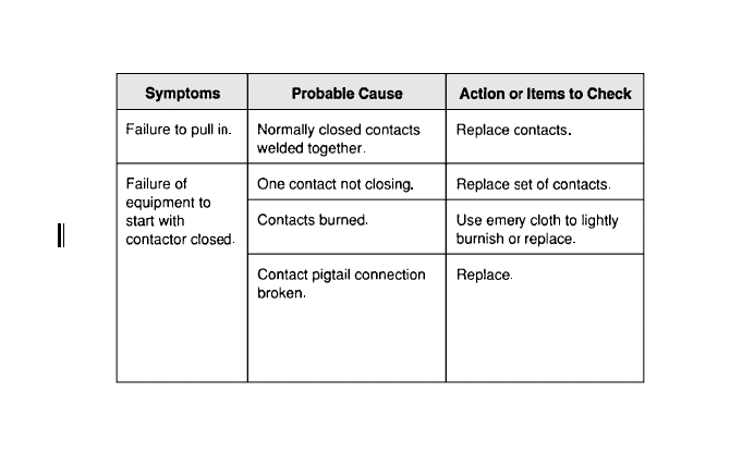
181
8-3 Contactor and relay troubleshooting chart. (Continued)
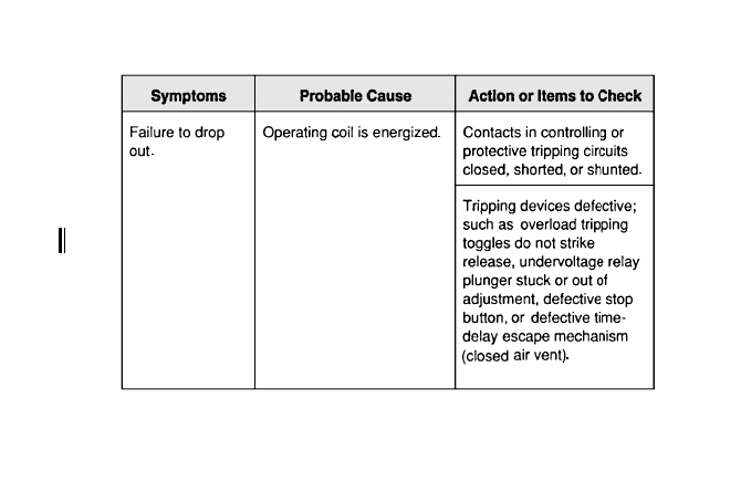
182
8-3 Contactor and relay troubleshooting chart. (Continued)
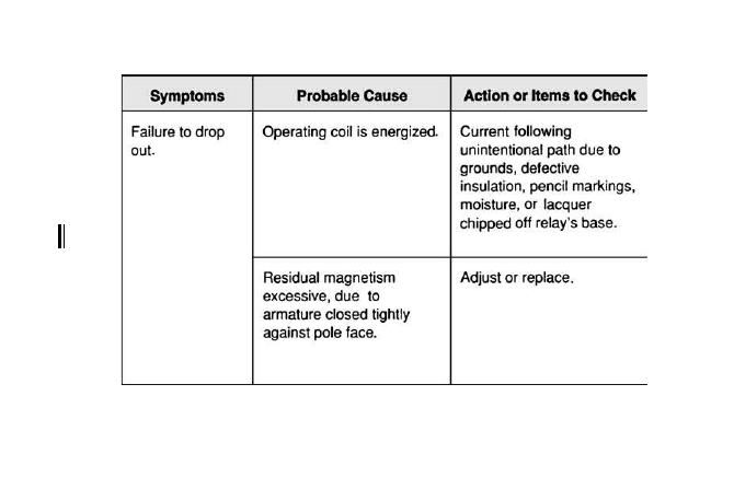
183
8-3 Contactor and relay troubleshooting chart. (Continued)
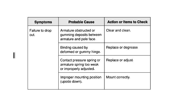
184
8-3 Contactor and relay troubleshooting chart. (Continued)
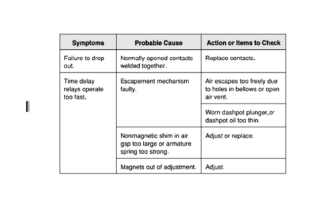
185
8-3 Contactor and relay troubleshooting chart. (Continued)
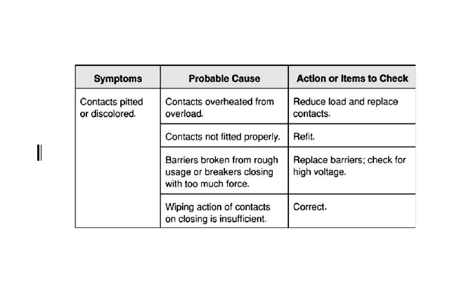
186
8-3 Contactor and relay troubleshooting chart. (Continued)
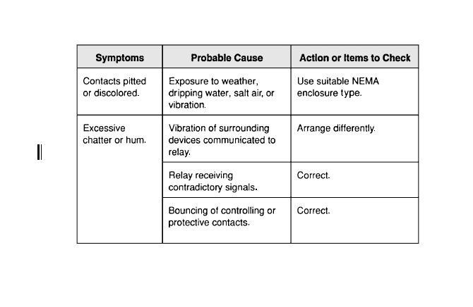
187
8-3 Contactor and relay troubleshooting chart. (Continued)
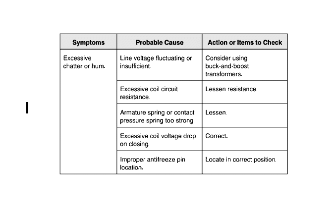
188
8-3 Contactor and relay troubleshooting chart. (Continued)
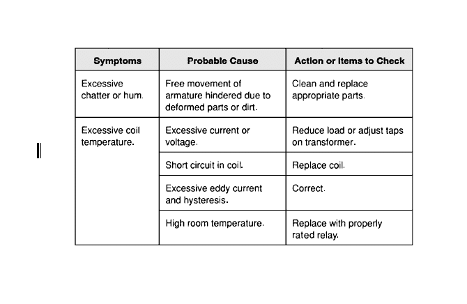
189
8-3 Contactor and relay troubleshooting chart. (Continued)

This page intentionally left blank

A
power quality problem is any change of voltage,
current, or frequency that results in failure or
reduced performance of end-user equipment. In real-
life electrical power systems, voltages and currents are
generally not the pure 60-Hz sine waves shown in
textbooks (Figure 9-1). Instead, the waveform is typi-
cally distorted by voltage transients, harmonics, and
other phenomena (Figure 9-2). These waveforms can
be displayed on the screens of power monitors and
other instruments to diagnose power quality prob-
lems. Power quality problems can be caused by many
factors:
●
Voltage levels (steady state) and voltage
stability (surges and sags)
●
Current balance (phase loading)
●
Harmonics
●
Power factor
●
Grounding
●
Overheated terminals and connections
●
Faulty or marginal circuit breakers
191
Copyright © 2007, 2000, 1996 by The McGraw-Hill Companies, Inc.
Click here for terms of use.
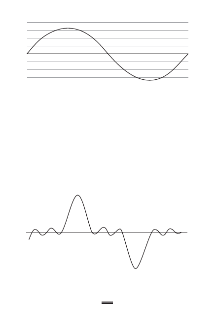
Monitoring
Recording monitors are typically installed to record
power system characteristics over a period of time,
such as 24 hours, or 7 days. This long-term monitor-
ing provides information on whether a power quality
problem was caused by a one-time random event, or
a repetitive recurring event. Often, power quality
192
9-1 Ideal sine waveform representing voltage or
current.
9-2 Sine waveform distorted by power quality
problems.

problems are not caused by a single event, but by a
combination of factors (such as voltage drop, utility
transients, harmonics, and improper neutral-to-ground
connections).
Power can be monitored at different locations in an
electrical power system:
At the load: Placing a monitor at the branch cir-
cuit supplying a motor or other piece of utiliza-
tion equipment analyzes the power quality at
the point of use.
At the distribution equipment: Placing a monitor
on the feeder to a panelboard or motor control
center (MCC) analyzes the power quality in an
entire section of a building.
At the service: Placing a monitor at the incoming
service conductors to a switchboard or other ser-
vice equipment analyzes the power quality in an
entire building (Figure 9-3). This is where capaci-
tors are typically installed to improve power factor
for the reason of avoiding utility penalty charges.
Voltage Levels and Stability
Voltage Levels
Check voltage levels at the main panel terminals and
each branch circuit. Voltage at the panel should ide-
ally be 120/208 or 277/480 V, three-phase, four-wire.
Voltage at receptacles or utilization equipment may
be lower due to voltage drop on branch circuits, but
should ideally be no less than 115/200 or 265/460 V.
193
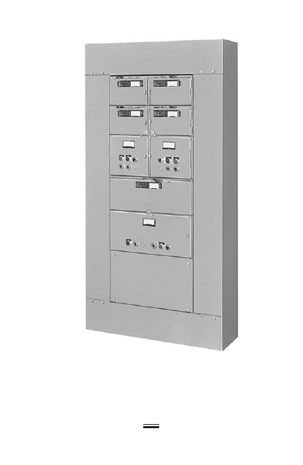
194
9-3 Service equipment: main distribution panel.
(Courtesy of Schneider Electric Company.)
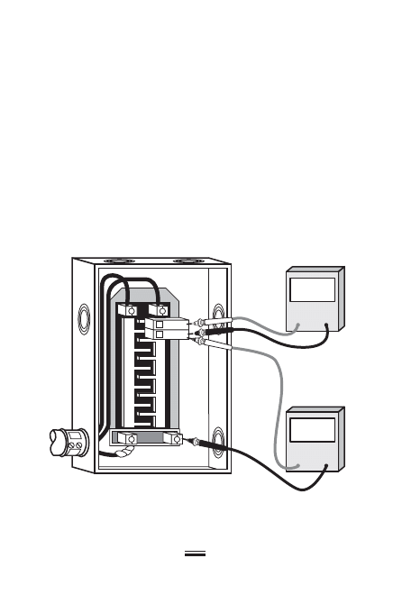
For safety, take voltage measurements on the load side
of main or branch circuit breakers whenever possi-
ble. This precaution helps protect the test instru-
ment and operator from potential fault currents on
feeders (Figure 9-4).
Low voltage causes electric motors to run slower
than their design speed, incandescent lights to burn
dimmer, starting problems for fluorescent and HID
lamps, and performance problems for electronic and
data devices. Overvoltage causes motors to run faster,
shortens incandescent lamp life, and can damage sen-
sitive electronic components.
195
114
Volt
218
Volt
9-4 Safe voltage measurement technique at panel
board.

Most electrical and electronic equipment are
designed to tolerate a range of ±10 percent of rated
voltage and still operate satisfactorily. However, pan-
elboard voltages in the range of 115/200 or 265/460 V
will probably translate into unacceptably low voltages
at receptacles or utilization equipment, due to addi-
tional voltage drop on the branch circuit conductors.
Common causes of low voltage at the panel are low
tap settings at transformers, feeder conductors that
are too long or too small, and loose connections. The
first condition results in lower supply voltage; the
latter two result in higher impedance that increases
voltage drop.
Voltage Stability
Voltage sags can be caused by either loads on branch
circuits, or elsewhere in the distribution system, includ-
ing utility-generated sags and brownouts. This is most
easily analyzed using an instrument such as a power
quality analyzer that measures both voltage and cur-
rent simultaneously. Take measurements at each branch
circuit in the panelboard.
Voltage sag occurring simultaneously with a current
surge usually indicates a problem downstream of the
measurement point. This would be a load-related distur-
bance on the branch circuit.
Voltage sag occurring simultaneously with a current
sag usually indicates a problem upstream of the mea-
surement point, originating elsewhere in the distribu-
tion system. Typical source-related disturbances include
large three-phase motors coming on line (starting) or
sags in the utility network.
196

Current Loading
Measure the current on each feeder phase and branch
circuit (Figure 9-5). It is important to make these mea-
surements using a true-RMS ammeter or digital multi-
meter (DMM). Because the combination of fundamental
and harmonic currents results in a distorted waveform,
a lower-cost average-sensing meter will tend to read
low, leading you to assume that circuits are more lightly
loaded than they actually are.
Loading on the three phases should be as balanced
as possible. Unbalanced current will return on the neu-
tral conductor, which may already be carrying a high
load due to harmonics caused by nonlinear loads. In an
ideal, balanced, three-phase electrical distribution sys-
tem, there is little or no load on the neutral.
Neither the panel feeder nor branch circuits should
be loaded to the maximum allowable limit (80 percent
of the overcurrent device rating, for continuous loads).
There should be some spare capacity to allow for har-
monic currents.
Harmonics
Harmonics are frequencies that are multiples of the
fundamental frequency (120 Hz, 180 Hz, 240 Hz, and so
on). High-frequency harmonic currents caused by non-
linear loads such as computers, adjustable speed motor
drives, programmable controllers, and fluorescent fix-
tures with electronic ballasts can cause significant heating
in power distribution systems, particularly in grounded
(neutral) conductors. Harmonics affect the operation or
197
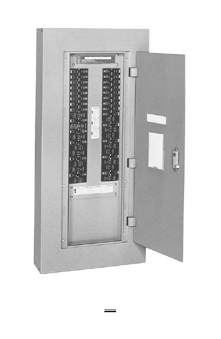
198
9-5 Branch-circuit panelboard. (Courtesy of Schneider
Electric Company.)
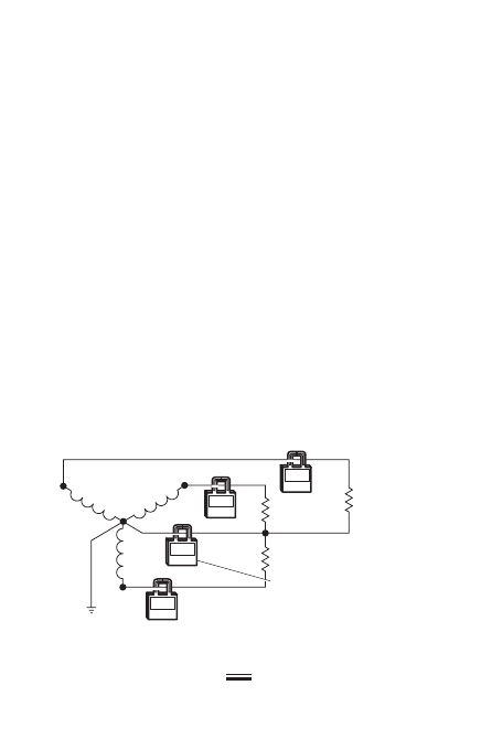
equipment such as motors, transformers, and overheat-
ing of neutral conductors.
Triplen Harmonics
Triplen harmonics are the following multiples of the
fundamental frequency: 3, 6, 9, 12, and so on. They
are very harmful for power quality because triplen
harmonic currents can add up in the neutrals of the
three-phase power systems, as shown in Figure 9-6.
Nonlinear loads include such common electrical
equipment as switched-mode power supplies used in
computers and their peripherals, and fluorescent or
HID fixture ballasts.
Overloaded neutrals are a potential fire hazard
because, unlike phase conductors, they are not pro-
tected by an overcurrent device. Third harmonics can
overload system neutral conductors even when loads
have been balanced among the three phases.
For this reason, National Electrical Code 310.15(B)
(4)(c) requires that “On a four-wire, three-phase, wye
199
100
Amps
100
Amps
200
Amps
100
Amps
L1
L2
L3
100 A
Nonlinear
100 A
Nonlinear
Up to 200% of the phase
current for harmonic
neutral current.
100 A
Nonlinear
A
2
A
1
A
0
A3
9-6 Effect of harmonics due to nonlinear loads.

circuit where the major portion of the load consists of
nonlinear loads, harmonic currents are present in the
neutral conductor; the neutral shall therefore be con-
sidered a current-carrying conductor.”
In effect, this requires that neutral conductors of
such three-phase, four-wire systems be at least the
same size as the phase conductors. In practice, neu-
trals of systems serving a high proportion of nonlin-
ear loads (such as office areas with multiple computers
and fluorescent lighting) are sometimes even larger,
up to double the size of the associated phase conduc-
tors (Figure 9-6).
Multiwire Branch Circuits
Common neutrals shared by either two or three single-
phase branch circuits are subject to the same over-
loading as neutrals of three-phase panel feeders, due
to asymmetrical loading and third harmonics.
Harmonic currents in feeder or branch circuit
grounded (neutral) conductors can be measured using
a DMM, or by using a probe-type meter to measure
the potential from neutral to ground (Figure 9-7).
Grounding
The neutral and grounding electrode conductor
should be bonded together only once, at the service
entrance or distribution point of a separately derived
system. Other neutral-ground connections elsewhere
in the system, such as subpanels or receptacle outlets,
are a violation of the National Electrical Code.
Unfortunately, improper downstream connections
between neutral and grounding conductors are also
200
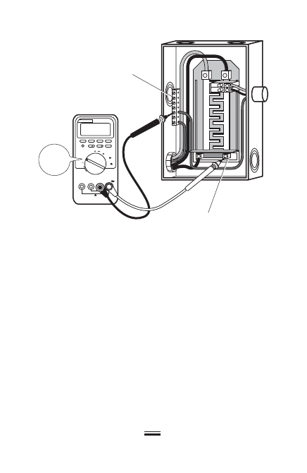
very common, and they are frequently a source of
power quality problems.
When the neutral and grounding electrode con-
ductors are bonded at a subpanel or other location,
the ground path becomes a parallel return path for
normal load current, and there will be measurable
current on the ground.
To determine whether improper connections exist,
measure the current on the grounded (neutral) con-
ductor and then on the grounding electrode conduc-
tor and look at the ratio between them. For example,
if the neutral current is 70 A and the ground current
is 2 A, the small ground current probably represents
201
OFF
V
V
mV
mA
A
A
HOLD
RANGE
A mA A COM V⍀
⍀
PLUKE 87 III
V
Ground bus
Neutral bus
9-7 Measuring neutral current.

normal leakage. But if the neutral measures 40 A and
the green ground measures 20 A, this probably indi-
cates that there are improper neutral-ground connec-
tions. The smaller the ratio of neutral-to-ground current,
the more likely it is that neutral-ground binds exist.
All neutral-to-ground connections not permitted
by the National Electrical Code should be removed.
This will improve both safety and power quality.
Overheated Terminals and
Connections
Poor connections and loose terminations increase cir-
cuit impedance and thus voltage drop. They can also
cause hard-to-diagnose intermittent problems, such
as circuits that cycle on and off unpredictably (a loose
connection may open when it heats up, and then
close again when it cools down).
“Hot spots” indicating possible poor connections
and terminations can often be found using thermal
scanning, which is discussed further in Chapter 10.
Visual inspection may also be useful. A preventive
maintenance program of checking and tightening
conductor connections on a regular basis can help
prevent this type of problem before it occurs.
Circuit Breakers
Although molded-case circuit breakers typically have
long service lives, contacts and springs can wear out,
particularly when the device has tripped frequently or
been used as a switch to turn equipment or circuits on
202
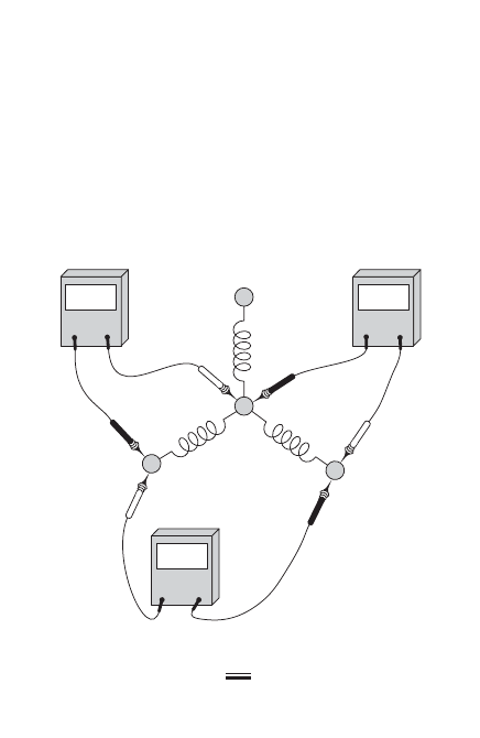
and off. As with other poor connections, marginal
breakers increase circuit impedance and voltage drop.
Overheating due to their poor internal connections
may also lead to “nuisance tripping.”
Measure voltage drop across the circuit breaker,
from line side to load side, to determine the condition
of internal components (see Figure 9-8). If voltage
drop exceeds 100 millivolts (mV), the branch circuit
breaker should be replaced. Readings in the 35 to
203
Ohm
1.0
Ohm
0.5
Ohm
0.5
A
B
C
9-8 Measuring voltage drop across circuit breaker.

100 mV range should be noted and those breakers
rechecked at regular intervals.
Power Factor
Power factor is a key element of power quality; it is
computed as real power (volt-amperes) divided by
apparent power (watts). Both electric utilities and
facility engineers typically try to maintain power fac-
tor as close to unity (1.0) as possible. However, many
types of equipment and devices attached to modern
electric supply systems cause either a leading or lag-
ging power factor, because impedance causes a phase
shift between the voltage and current waveforms.
Power factor is a measure of how efficiently a load
uses electricity or how much energy is consumed by
the load versus how much the utility must provide.
Electric utilities frequently levy high penalties on large
electricity users (industrial plants, office campuses)
that fail to keep power factor above some minimum
such as 0.95 power factor.
Impedance
Impedance is at the heart of power factor. Typically,
there should be an impedance value of less than 0.5 Ω
between the phase and grounded (neutral) conductor,
and between the neutral conductor and equipment
grounding conductor.
Figure 9-9 summarizes power quality troubleshoot-
ing recommendations.
204

205
9-9 Troubleshooting chart for power quality problems.
Symptoms
Probable Cause
Action or Items to Check
Low voltage levels at
panelboard or service
entrance equipment.
Utility supply voltage
too low.
Consult utility.
Voltage sag coincides
with current surge, when
measured at panelboard.
Downstream load with
high inrush current, such
as motor(s) or
incandescent lighting.
Consider feeding sensitive
loads from other circuits
or panelboards.
Voltage surge coincides
with current decrease,
when measured at
panelboard.
Upstream source-related
disturbance.
Consult utility.
Transformer tap settings
too low.
Use higher voltage taps.
Loose connection in
feeder service
conductors.
Check connections.

206
Symptoms
Probable Cause
Action or Items to Check
Significant neutral
current on three-phase
feeder.
Unbalanced loading on
different phases of
panelboard.
Balance panelboard.
Current on neutral of
three-phase feeder
equals or exceeds
phase currents.
Harmonics generated by
nonlinear loads.
Increase size of feeder
neutral conductor.
Neutral-to-ground
potential exceeds
0.5 V.
Neutral-to-ground
connections at panels
other than service
entrance equipment.
Remove improper
neutral-to-ground
connections.
Current on shared neutral
of multiwire branch of
circuit equals or exceeds
phase currents.
Harmonics generated by
nonlinear loads.
Use individual two-wire
branch circuits.
9-9 Troubleshooting chart for power quality problems. (Continued)

207
Symptoms
Probable Cause
Action or Items to Check
Low voltage levels
at receptacles or
utilizations equipment.
Long branch circuit runs.
Install oversized conductors
to compensate for voltage
drops.
Loose connections in
branch circuits.
Check and tighten
connections.
Voltage drop across
circuit breaker exceeds
100 mV, from load
to line side.
Worn circuit breaker
contacts and springs.
Replace circuit breaker.
9-9 Troubleshooting chart for power quality problems. (Continued)

This page intentionally left blank

I
nfrared thermography (also called thermal scanning)
is an important diagnostic tool for troubleshooting
electrical equipment and systems. Overheating can be
a symptom of many different kinds of problems, and
equipment typically goes through a stage where it
gives off heat before an actual physical failure occurs.
This heat is infrared radiation, in energy wavelengths
(invisible to the human eye).
Infrared thermography uses infrared cameras to
“see” and measure the thermal energy being emitted
by overheated electrical equipment. This information
is used to pinpoint electrical problems before failures
occur. Infrared cameras, in effect, take photographs of
electrical equipment by detecting heat energy rather
than visible light. Infrared thermography is used to
detect the following general types of electrical main-
tenance problems:
Poor Connections: Vibration and thermal cycling
can cause electrical connections to loosen. Mois-
ture and contamination can corrode connections.
209
Copyright © 2007, 2000, 1996 by The McGraw-Hill Companies, Inc.
Click here for terms of use.

Poor connections cause hot spots that are easily
detected using infrared cameras.
Overloaded Conductors: Overloaded electrical
conductors typically cause protective devices
such as circuit breakers and fuses to operate.
When they don’t, the overloaded conductors
run hotter than usual.
Short Circuits and Ground Faults: Short circuits
and ground faults (a short circuit involving an
equipment ground) also should cause protective
devices to operate. But sometimes the current,
while not sufficient operate a circuit breaker or
ground fault relay, is sufficient to damage con-
ductor insulation and cause overheating that
can ignite a fire.
Harmonics: High-frequency harmonic currents
caused by electronic loads such as computers,
adjustable speed motor drives, and fluorescent
fixtures with electronic ballasts can cause signif-
icant heating in power distribution systems, par-
ticularly in grounded (neutral) conductors.
Mechanical problems: Problems such as loose cou-
plings and misalignment of motor shafts cause
overheating that can be detected by thermal
scanning.
The troubleshooting chart in Figure 10-1 lists typi-
cal operational problems of electrical equipment that
210
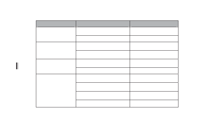
211
Symptoms
Probable Cause
Action or Items to Check
Loose or corroded terminal.
Tighten or replace terminal.
Overheated terminal
or connection.
Damaged conductor.
Replace conductor.
Insulation failure.
See Chapter 8.
Transformer
overheats.
Shorted turns in transformer
core.
See Chapter 8.
Loose connection.
Tighten or repair connector.
Transformer bushing
overheats.
Internal fault.
See Chapter 8.
Misaligned shaft.
See Chapter 10.
High or low voltage.
See Chapter 10.
Shorted stator coil.
See Chapter 10.
Motor overheats.
Faulty connection.
See Chapter 10.
10-1
Troubleshooting chart for problems identified with thermal scanning.

can be identified using thermal scanning (infrared
thermography).
Safety Considerations
Infrared thermography is a noncontact troubleshoot-
ing technique. It is typically performed on energized
systems operating at full load.
However, while it’s not necessary for an infrared
camera or electronic thermometer to contact the equip-
ment, in many cases thermal scanning is still hazardous
work. This is because it is often performed on energized
equipment such as panelboards and switchboards, with
the covers removed. A mistake can result in accidental
contact with “live” parts and possible electrocution,
burns, or arc-flash injuries to the technicians.
For this reason, all thermal scanning work around
exposed conductors and equipment must be per-
formed in accordance with NFPA 70E-2004, Standard
for Electrical Safety in the Workplace—particularly min-
imum approach distances and proper use of personal
protective equipment (PPE).
212

AC circuits, voltmeters for, 7
AC motors testing, 16
Acceleration issues, of motors,
Accessories, for DMMs, 29
Accuracy:
of ammeters, 3–4
with clamp-on ammeters, 3–4
of digital multimeters, 25, 26
Air gap feeler gauges, 94
Alignment, of bearings, 101–102
Alternating-current motors, 159
Ammeters, 2–6
accuracy of, 3–4
applications of, 4–5
clamp-on, 2–4, 93
in electric baseboard heater,
recording, 5–6
in three-phase motor, 4
volt-ohm-ammeters, 12, 13
Analog test instruments (analog
ammeters, 2–6
cable-length meters, 22
electrical thermometers,
footcandle meters, 21
frequency meters, 19
megohmmeters, 13–19
Analog test instruments
(analog meters) (Cont.):
phase-sequence indicator, 22
power factor meter, 19
power quality analyzers, 23–24
single-function, 1–2
tachometers, 20
types of, 1–2
usefulness of, 1
voltmeters, 6–13
Angular-contact ball bearings,
Apparent power, 204
Arc streams, 71–72
Arc tubes, of HID luminaires,
Arc-blasts, 44
Armatures, heat of, 131–132
Audible indicators (ammeter),
Backlighting switch (DMMs), 27
Ball bearings:
angular-contact, 162
double-row, deep-groove, 162
failure of, 159
heat of, 172
self-aligning, 160
single-row, deep-groove,
213
Copyright © 2007, 2000, 1996 by The McGraw-Hill Companies, Inc.
Click here for terms of use.

Ballasts:
in fluorescent luminaires, 58
noise in, 84–85
two-lamp, 61
Ball-thrust bearings, 162–163
Base:
of HID luminaires, 89
of incandescent lamp, 75
loose, 89
Bearings (see Motor bearings)
Bent shafts, in split-phase
Binoculars, 95
Blackening, of ends of lamps:
within 1 inch of ends, 67
in brownish ring, 70
with dark streaks, 70
dense, 66–67, 69
early in life, 68–69
extending 2–3 inches from
of HID luminaires, 89
of inner arc tube, in HID
short lamp life and, 63–66
spot, 69
Blinking, of fluorescent
Branch circuit(s):
harmonics and, 200, 201
multiwire, 200, 201
panelboards, 198
Brightness, unequal (fluorescent
Brownouts, 196
Brushes:
sparks at, 137–141
wear of, 141–144
Bulbs, of incandescent lamp, 75
Burned insulation, in dry-type
Button, of incandescent lamp, 75
Button rod, of incandescent
Cable insulation testing, 13–14
Cable-length meters (time-
domain reflectometers,
TDRs), 22
Calibration, 51
Cameras, infrared (see Infrared
cameras)
Canvas strips, 95
Capacitance measurements,
Capacitors, 38
Capture (hold, freeze) mode
CAT I, 37
CAT II, 37
CAT III, 36, 37
CAT IV, 36
Cathodes, in fluorescent
Centrifugal switches, defective,
Chatter, in contactors and
Circuit(s):
AC, 7
DC, 6, 7
harmonics and, 200, 201
multiwire branch, 200, 201
open, 49–53, 98
short, 103–104, 210
Circuit breakers:
power quality problems in,
testing, with megohmmeters,
tripped, 40–41
voltage drop across, 203, 207
214

Circuit grounded (neutral)
accuracy with, 3–4
currency measurements with,
for electric motor
maintenance, 93
Clamp-on power factor meters,
Cleaning solvents, 94
Closed contactors, 181
Clothing hazards, 45
Coil(s):
distortion of, 55
in dry-type transformers, 55
in electric motors, 92, 96–97
grounded, 92, 96
shorted, 96–97
temperature of, 189
Coil connections:
in electric motors, 98–99
reversed, 98–99, 102–103
Color, abnormal (see
Discoloration)
Common or return (COM)
Commutators:
heat of, 133–134
issues with, in motors,
Complete shorts, in dry-type
Computerized (digital) meters,
Concentric coils, wye
Conductor(s):
circuit grounded, 200
loss, in dry-type transformers,
Conductor(s) (Cont.):
neutral electrode, 200, 201
overloading of, 210
Connections:
corroded, 209
delta connections, 100
downstream connections,
in electric motors, 98–99
neutral-to-ground
overheated, 202, 211
reversed, 98–99, 102–103
Wye connections, 100,
Contamination, 209
Continuity, 52
digital multimeters and,
Continuity Capture mode
Core loss, in dry-type
Core-and-coil fluorescent
215

Current:
in DMMs, 28
in fluorescent luminaires, 58
instantaneous, 5
Current decrease, 205
Current loading, 197
Current measurements:
with clamp-on ammeters, 2–3
with digital multimeters,
digital multimeters for, 197
Current sag, 196
Current surges, 196, 205
Cycling, thermal, 209
Cylindrical-roller bearings, 162
DC circuits, 6, 7
DC motors and generators
Decreased light output:
of fluorescent luminaires,
of incandescent luminaires,
De-energized systems:
lockout/tagout in, 46–47
open-circuited transformer, 49
Defective centrifugal switches,
Delta connections, 100
Delta-wound motors:
Dielectric testers, portable oil, 94
Digital (computerized) meters,
Digital multimeters (DMMs),
accessories for, 29
accuracy of, 25, 26
for capacitance measurements,
Digital multimeters (DMMs)
(Cont.):
capture mode of, 27
category number of, 37
construction features of,
for continuity testing, 31, 33
convenience features of,
for diode testing, 33, 35
display of, 26–27, 43
features of, 27–28
freeze mode of, 27
for frequency measurements,
function selection in, 28
hold mode of, 27
inputs for, 28–29
modes of, 27
for motor leads testing, 114
power quality analyzers vs., 23
for resistance measurements,
safety features of, 36–37
safety precautions for, 37–38
safety ratings of, 36
test leads for, 28–29
Underwriters Laboratories,
using, 29–35
for voltage measurements,
Dim light (see Decreased light
output)
Diode testing:
Direct (two-terminal) test, 17
216

Dirty motors, 116–117
Disassembly, of electrical
Discharging capacitors, 38
Discoloration:
of contactors and relays,
Displays:
of digital multimeters, 26–28,
in grounded coil, 96
infinity in, 96
liquid-crystal diode, 27, 28
overlimit, 38
of power quality analyzers, 23
Distribution equipment
DMM (see Digital multimeters)
Double-row, deep-groove ball
Double-shielded bearings, 160
Downstream connections,
Drop out failure, 182–185
Dry-type transformers, 49–56
complete short in, 53–54
ground fault in, 53
grounded windings in, 54–56
noise in, 56
open circuit in, 49–53
overheating, 55
smoke, 56
smoke in, 56
vibrations in, 56
Earth-resistance testing, direct
Electric ballasts, in fluorescent
Electric baseboard heaters, 4–5
grounded coils in, 92, 96
identifying, 104–110
open circuit in, 98
recordkeeping, 110–115
reversed coil connections in,
reversed phase in, 99
shorted coils in, 96–97
split-phase motors, 101–104
three-phase delta-wound
troubleshooting chart for,
Electric tachometers, 20
Electrical failure, 41
Electrical hazards, 43, 44
Electrical thermometers, 21–22
Electromagnetic induction, 91
Electromotive force (EMF), 6
Excess secondary voltages, 55
Exciting currents, 56
Exhaust tubes, of incandescent
Faults, intermittent, 42–43
“Feel” test, 168
Fields, heat of, 134–135
Filament, of incandescent lamp,
Fire-rated (FR) clothing, 46
Fixtures, lighting
(see Luminaires)
217

FR (fire-rated) clothing, 46
Freeze (hold, capture) mode
Frequency, 19
Frequency measurements, with
Frequency meters, 19
“Frozen” (tight) bearings,
Function selection (DMM), 28
Fuses:
of DMM, 36
in dry-type transformers, 56
of incandescent lamp, 75
open, 56
testing, with voltmeters, 12
Gas, in lamps, 75
Generators, 14–15
Grinding rigs, 95
Ground(s), 92
Ground faults:
in dry-type transformers, 53
infrared thermography and,
Ground resistance testing,
Grounded coils, 92, 96
Grounded windings:
in dry-type transformers,
Grounding, 200–202
Grounding electrode
Hand-held test meters, 36
Hard stones, 95
Harmonics:
defined, 197
grounding, 200–202
infrared thermography and,
multiwire branch circuits
Hazards, 43, 44
High-intensity discharge (HID)
High-voltage transients, DMMs
Hold (freeze, capture) mode
“Hot spots,” 202, 210
Humidity, 63
Humming:
in contactors and relays,
Impedance, 204–207
Incandescent luminaires, 59,
Induction, electromagnetic, 91
218

Industrial electric service,
Inert gas, in tungsten-halogen
Infinity, in grounded coil
display, 96
Infrared thermography,
harmonics and, 210
overheating, 209
poor connections in, 209–210
safety considerations for, 212
short circuits and, 210
vibrations in, 209
Inner arc tubes, blackening of,
Inputs, for DMMs, 28–29
Instant start lamps, 58
Instantaneous current, 5
Insulation:
burned, 56
failure of, in dry-type
Insulation breakdown:
shorted coils and, 96
in transformers, 54
Insulation resistance tester, 94
Intermittent faults, 42–43
Iodine vapor, in tungsten-
Jewelry, and safety, 45
Lamp(s):
Lamp(s) (Cont.):
quartz-iodide, 59
tungsten-halogen, 59
(See also Luminaires)
Lamp breakage:
in HID luminaires, 86–87
in incandescent luminaires, 78
in outer bulb, of HID
Lamp life, short:
blackening and, 63–66
blackening at, 68–69
of fluorescent luminaires,
of incandescent luminaires,
Lamp-within-a-lamp design,
LCD displays (see Liquid-crystal
diode displays)
Lead-in wires, of incandescent
Lighting fixtures (see luminaires)
Liquid-crystal diode (LCD)
“Live” (see Working “live”)
“Lo Bat” warning (DMMs), 28
Load:
monitoring at, 193
motors under, 152–154
Lockout/tagout, 46–47
Long-term monitoring, 192
Low-voltage, 195, 196
causes of, 196
at panelboard, 205
at receptacles, 207
at service entrance equipment,
testing, 9
at utilization equipment, 207
voltmeters, for testing, 9
219

Lubrication:
frequency, of motor bearings,
of motors, 163, 167–168
procedure for, 167–168
Luminaires (lighting fixtures),
defined, by NEC, 57
fitting lamps to, 85–86
fluorescent, 58–74
high-intensity discharge, 76,
mA (milliampere), 29
Magnifying glass, 95
Main distribution panel, 194
MCC (motor control center),
Mechanical problems, 210
Megger (see Megohmmeters)
Megohmmeters (meggers), 1,
for AC motors testing, 16
cable insulation testing with,
for circuit breakers testing, 17
for DC motors and generators
for ground resistance testing,
Metal, and safety, 45
Microampere (µA), 29
Milliampere (mA), 29
Moisture, 209
Monitoring:
at distribution equipment,
at load, 193
long-term, 192
power quality problems,
at service, 193
Monitors, recording, 192
Motor(s):
AC, 16
acceleration issues of,
alternating-current, 159
ammeters in, 4
armature, heat of, 131–132
brush wear of, 141–144
commutate issues of, 137–141
commutator, heat of,
DC, 14–15
delta-wound, 110–115
dirty, 116–117
electric, 91–158
fast, 124–126
fields, heat of, 134–135
under load, 152–154
lubrication of, 163, 167–168
magnetic noise of, 158
megohmmeters and, 14–16
noisy, 144–146, 158
overheated, 129–130,
reverse direction of, 120
rotation of, 152
scraping noise of, 158
slow, 127–129
sparks at brush and, 137–141
speed issues with, 121–129,
220

Motor(s) (Cont.):
stalling, 147–148
start failure of, 119–120, 148
three-phase, 4, 110–115
unbalanced, 135–137
unbalanced line current of,
alignment of, 101–102
angular-contact ball bearings,
ball-thrust bearings, 162–163
cylindrical-roller bearings, 162
double-row, deep-groove ball
double-shielded, 160
frozen, 101
heat of, 169–171
lubrication frequency, 163, 167
lubrication procedure,
open bearings, 159–160
replacement of, 160
self-aligning ball bearings,
single-row, deep-groove ball
single-shielded bearings, 160
spherical-roller bearings, 162
spherical-roller thrust
in split-phase motors,
tapered-roller bearings, 163
testing, 168–173
tight, 101
types of, 159–167
worn bearings, 101
Motor control center (MCC), 193
Motor leads testing, 114
Motor rotation testers, 95
µ
Multimeters, 93
Multirange one-scale
Multiwire branch circuits:
harmonics and, 200, 201
neutral electrode conductors
Nameplates:
of electric baseboard heater, 4
for motor identification, 104
National Electric Code
(Article 100):
on grounding, 200
on luminaires, 57
on neutral-to-ground
on qualified persons, 44
on triplen harmonics,
Needles (indicator), 1
NEMA size 1 contactor, 177
NEMA Standards:
for lead markings for dual-
voltage, delta-wound
motors, 111
for lead markings for dual-
voltage, wye-wound
motors, 109
Neutral electrode conductors,
of multiwire branch, 206
on three-phase feeder, 206
Neutrals, overloading of, 199
Neutral-to-ground connections,
221

NFPA 70E-2004 (Standard for
Electrical Safety in the
Workplace), 44
on electrical testing, 45
on infrared thermography,
on personal protective
Noise (sounds, tones):
of ballast, 84–85
in contactors and relays,
in continuity tests with
in dry-type transformers, 56
in fluorescent luminaires,
of HID luminaires, 84–85
humming, in fluorescent
magnetic, 158
of motors, 144–146, 158
scraping, 158
Noncontact troubleshooting,
Nonlinear loads, 199
“Nuisance tripping,” 203
Odor, from insulation melting,
ODTRs (optical time-domain
Ohmmeters, 93
Oil dielectric testers, portable,
Oil filters, portable, 94
Oil leakage, from overflow
125-VAC duplex receptacle, 7
Open bearings, 159–160
Open breakers, in dry-type
Open circuits, 92
defined, 92
in dry-type transformers,
in electric motors, 98
in split-phase motors, 102
Open fuses, in dry-type
Optical pyrometers, 21–22
Optical time-domain
reflectometers
(ODTRs), 22
Outer bulb, lamp breakage of,
Overcurrent devices, opening of,
Overflow plugs, oil leakage
Overheating:
checking for, with voltmeters,
of connections, 202, 211
in dry-type transformers, 55
infrared thermography and,
of terminals, 202, 211
of transformer bushing,
Overlimit display (DMM), 38
Overloading:
of conductors, 210
of neutrals, 199
of transformers, 54
Overvoltages, 36, 195
Oxidized parts, of HID
222

Panelboards:
branch-circuit, 198
current surges at, 205
low-voltage at, 205
safety at, 45
safety with, 45
voltage measurement
voltage sags at, 205
voltage surges at, 205
Personal protective equipment
(PPE):
for infrared thermography, 212
safety with, 45–46
Phase, reversed (see Reversed
phase)
Phase-sequence indicator, 22
Phosphor, in fluorescent
Photo tachometers, 20
Pitted contactors, 186–187
Pointers (indicator), 1
Polyphase motors, unbalanced
Portable oil dielectric testers, 94
Portable oil filters, 94
Power, 204
Power cable testing, 13–14
Power factor, 204
Power factor meters, 19, 93
Power quality analyzers,
Power quality problems,
in circuit breakers, 202–204
current loading and, 197
harmonics and, 197, 199–202
impedance and, 204–207
monitoring, 192–194
overheated terminals and
Power quality problems (Cont.):
power factor of, 204
voltage levels and, 193,
PPE (see Personal protective
equipment)
Preheat fluorescent lamps, 58
Psychrometers, 94
Pull-in failure, of contactors
Qualified persons, 44
Quartz tube, in tungsten-
Quartz-halogen lamps (see
Tungsten-halogen lamps)
Quartz-iodide lamps (see
Tungsten-halogen lamps)
Radiation pyrometers, 21–22
Radio interference:
in fluorescent luminaires, 72
of HID luminaires, 84
Rapid start lamps, 58, 63
Rattling, of HID luminaires, 89
Real power, 204
Receptacles, low-voltage at, 207
Recording:
Recording mode, 42–43
Recording monitors, 192
Recordkeeping, 110–115
Relays, 175–176, 178–189
chatter in, 187–189
coil temperature and, 189
defined, 175
discolored contacts and,
223

Relays (Cont.):
fast operation of, 185
hum in, 187–189
noise in, excessive, 187–189
pitted contacts and, 186–187
pull in failure of, 178–181
single-pole, single-throw, 176
starter issues of, 181
time delay, 185
Resistance measurements:
with digital multimeters,
Resistance thermometers, 21
Reverse direction of motors, 120
Reversed coil connections:
in electric motors, 98–99
in split-phase motors,
Reversed grounds, 102–103
Reversed phase, 99
Rotating equipment speed, 20
Rotation, of motors, 95, 152
Safety:
with capacitors, 38
with diode testing, 38
dress for, 45
with infrared thermography,
with lockout/tagout, 46–47
metal and, 45
at panelboards, 45
with panelboards, 45
with personal protective
qualified persons and, 44
with resistance measurements,
troubleshooting tips for, 43–46
working “live” and, 46
Safety equipment, 45
Safety features, of DMM, 36–37
Safety precautions, for DMM,
Safety switches testing, 17
Scanning, thermal (see Infrared
thermography)
Scraping noise, 158
Self-aligning ball bearings, 160
Service, monitoring at, 193
Service entrance equipment,
Shimmering, of fluorescent
Short(s), 53–54, 92
Short circuits:
infrared thermography and,
in split-phase motors,
Shorted coils:
in electric motors, 96–97
insulation breakdown and, 96
Sine waveform, 192
Single-function analog meters,
Single-pole, single-throw (SPST)
relay, 176
Single-row, deep-groove ball
Single-shielded bearings, 160
Sleeve bearings:
failure of, 159
heat of, 170–171
Smoke, in dry-type
“Soft keys” (DMMs), 28
“Sound” test, 168
Sounds (see Noise)
Speed issues, 121–129, 149–151
Spherical-roller bearings, 162
224

Spherical-roller thrust bearings,
reversed coil connections in,
short circuits in, 103–104
tight bearings in, 101
Spot blackening, 69
Spring tension scales, 95
SPST (single-pole, single-throw)
relay, 176
Stalling, of motors, 147–148
Starter (fluorescent lamps), 58
Starter issues:
of contactors and relays,
of fluorescent luminaires, 62
of HID luminaires, 79–80
lack of, in fluorescent
Stationary (stator) windings, 91
Stem press, of incandescent
Stethoscopes, transistorized, 93
Streaks, dark (in lamps), 70
Stroboscopic effect, of HID
Sunburn (suntan), of HID
Support wires, of incandescent
Switchboards, three-phase
Switches:
centrifugal, 102
defective centrifugal, 102
safety, 17
Switchgears testing, 17
“Switching operations” safety,
Tachometers, 20, 93
Tagout (see Lockout/tagout)
Tapered-roller bearings, 163
TDRs (time-domain
reflectometers, cable-length
meters), 22
Terminals, overheated, 202, 211
Test instruments, analog (see
Analog test instruments)
Test leads:
for digital multimeters,
Thermal cycling, 209
Thermal scanning (see Infrared
thermography)
Thermocouples, 21
Thermography, infrared (see
Infrared thermography)
Thermometers:
electrical, 21–22, 94
resistance, 21
Three-phase delta-wound
Three-phase feeder, 206
Three-phase motors, 4
Three-phase power factor
Thrust bearings, 162–163
Tight (“frozen”) bearings,
Time-domain reflectometers,
Time-domain reflectometers
(TDRs, cable-length
meters), 22
Tones (see Noise)
Transformers:
dry-type, 49–56
insulation breakdown in, 54
overheating, 53, 211
225

Transformers (Cont.):
overheating of bushing of,
overloading of, 54
winding, 53–54
Transistorized stethoscopes, 93
Triplen harmonics, 199–200
Tripped circuit breakers, 40–41
Troubleshooting, 39–47
with continuity capture
correcting cause of trouble,
with disassembly, 41
finding cause of trouble,
for intermittent faults, 42–43
noncontact, 212
with recording mode, 42–43
for safety, 43–46
thinking before acting, 40–41
(See also specific topics, e.g.,
Dry-type transformers)
Tungsten-halogen (quartz-
halogen, quartz-iodide)
lamps, 59, 75
25-kVA three-phase unit, 50
Two-terminal (direct) test, 17
UL categories, 37
UL Standard 3111-1, 36
Unbalanced motors, 135–137
Underwriters Laboratories
Unequal brightness, 73–74
Utility-generated sags, 196
Utilizations equipment, low-
V (volt), 6
Vibrating-reed tachometers, 20
Vibrations:
in dry-type transformers, 56
infrared thermography,
of motor, 135–137,
Volt (V), 6
Voltage:
in DMMs, 28
drop in, across circuit breakers,
in dry-type transformers, 55
excess secondary, 55
levels of, 193, 195–196
low, 195, 196, 205, 207
at 125-VAC duplex receptacle,
power quality problems and,
range of, in voltmeters,
Voltage measurements:
with digital multimeters,
Voltage sags, 196, 205
Voltage surges, 205
Voltage to ground, 56
Voltmeters (analog), 6–13
for AC circuits, 7
applications of, 8
common types of, 12, 13
connecting, to circuit, 6
for DC circuits, 6, 7
for electric motor
fuse testing with, 12
ground faults and, 9–13
for low-voltage test, 9
multirange one-scale, 8
226

Voltmeters (analog) (Cont.):
for overheating checks, 53
voltage ranges of, 7, 8
Wattmeters, 93
Wet motors, 118
Windings:
in dry-type transformers,
Windings (Cont.):
stationary, 91
testing of, 92
transformers and,
Working “live,” 44, 46, 212
Worn bearings, 101
Wye connections, 100, 106
with concentric coils, 100
lead markings for
227
Wyszukiwarka
Podobne podstrony:
Halley RF Troubleshooting and Maintenance Guide V1 0
Electronics 4 Systems and procedures S
Darrieus Wind Turbine Design, Construction And Testing
Pocket Guide to Chemical Engineering
Pocket Guide to Chaos Magick
Asperger's Disorder A Medical Dictionary, Bibliography, And Annotated Research Guide To Internet Ref
EV (Electric Vehicle) and Hybrid Drive Systems
Electronics 1 Materials and com Nieznany
Electronics 4 Systems and procedures S
Templum Pocket Guide To Thelema
Implementing and testing a virus throttle
Microsoft Dynamics CRM Online security and compliance planning guide
Pocket Guide to Kabbalah
Cannabis A Medical Dictionary, Bibliography and Annotated Research Guide to Internet References (20
Chocolate Lovers 3 Troubles and Treats Tara Sivec
Pocket Guide to Witchcraft
Templum Pocket Guide To Tarot
więcej podobnych podstron