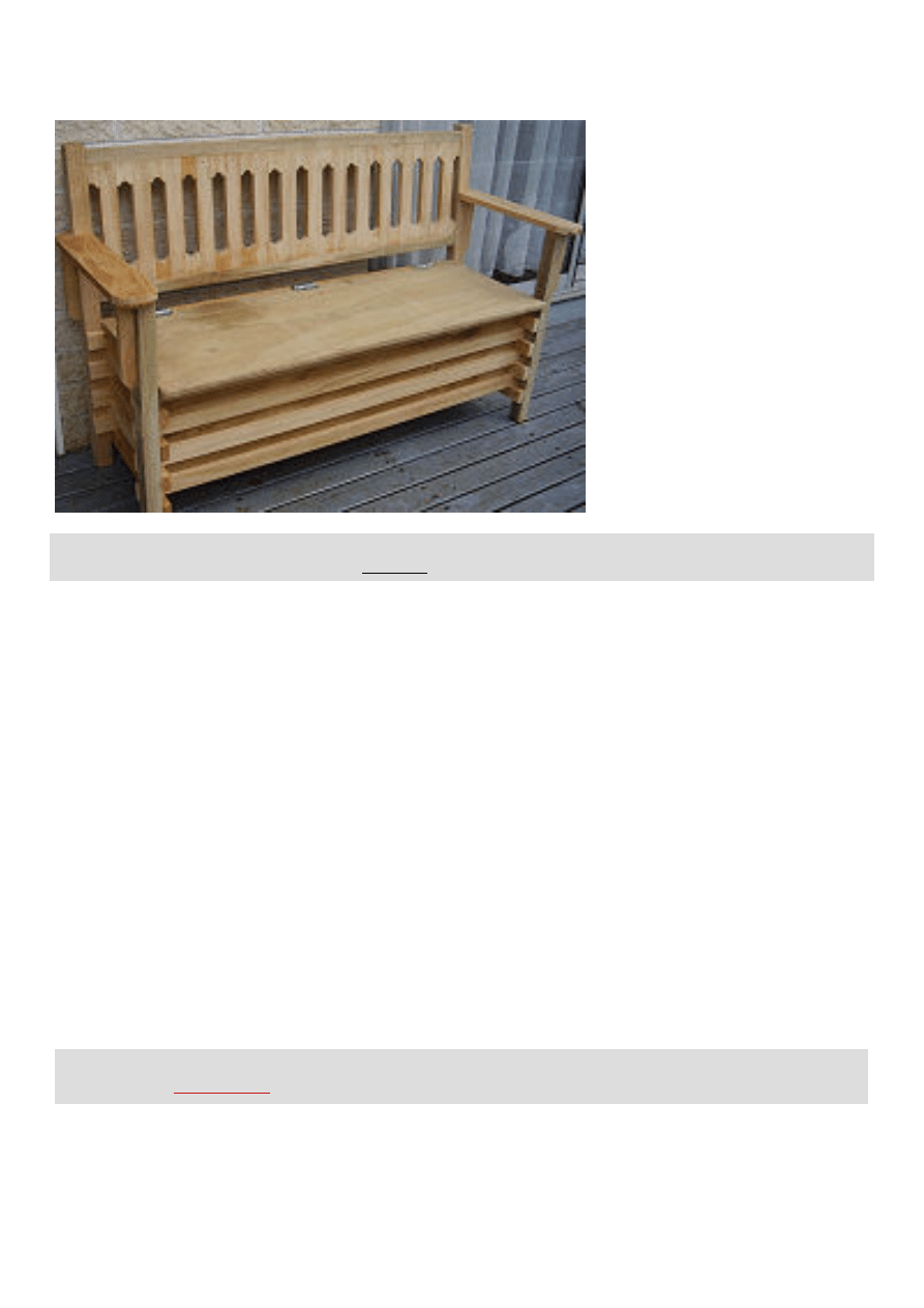
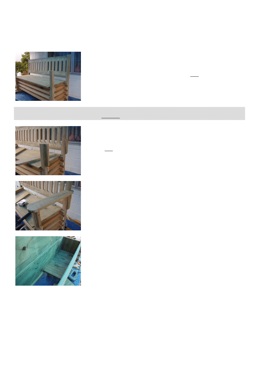
Boot Bench
NOTE: This complete plan-set can be purchased in downloadable PDF format with more pictures free of advertising
and print friendly for only $5. For more info click here
Introduction
This handy boot bench can be made in just a day. It is constructed in a typical DIY fashion i.e. it avoids complicated
joints which might be too tricky for the less seasoned woodworker.
Level of expertise required? If you can comfortably rip wood (cut down lengthwise) with a circular power saw, then
you should be able to undertake this project.
This particular bench was constructed outside on a picnic table under a tarpaulin on a rainy day, so it goes to show
you do not necessarily need an elaborate work shed.
Minimum power tool requirements Circular power saw, jig-saw, drill. (Mind you, a chop saw would be handy.)
Of course you will also need the usual basic hand tools which are: handsaw, pencil, measuring tape, hammer, nail set,
large square and a couple of clamps.
Nails and/or screws. We have used a mixture of nails and screws in this project. Nails are used for the most part as
they can be set-in and the nail holes easily filled if painting or staining is required. Screws are used in places that
require a bit of extra holding power and are generally only used in less conspicuous places.
About the wood dimensions. All dimensions are given in both Metric (mm) and Imperial (inches). The size (width
and thickness) of the wood referred to throughout this project is the actual size. That is the size of the lumber when it
has been dressed, planed and/or seasoned. When the wood has been dressed, planed and/or seasoned it is then
called the 'actual size' which is the true size. Before the lumber has been dressed, planed and/or seasoned it is called
the 'nominal size'. For example: 50mm x 25mm (1" x 2") when dressed may become 40mm x 18mm (3/4"x 1 1/2")
actual size.
Note: The metric (mm) sizes given in this project do not convert exactly to their corresponding ft and inch
equivalents. >>
Find out why
.
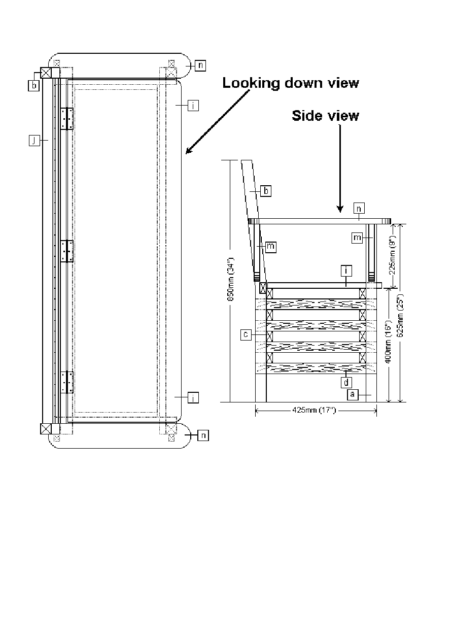
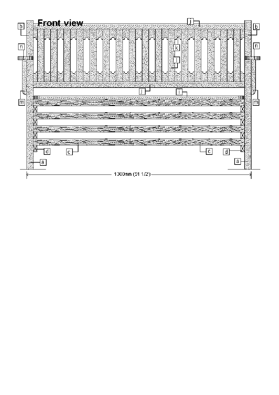
Below are the plan drawings and cutting list with a drawing of most of the required pieces.
Under the drawings are descriptions along with dimensions of all the pieces that are in the plans.
The instructions are on successive pages.
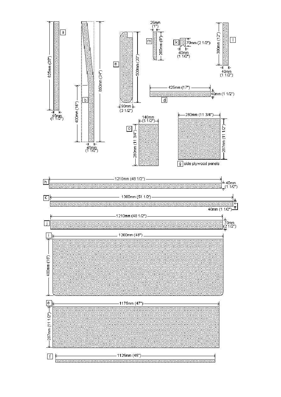
Below is a description of all the pieces of wood including sizes, lengths and amounts.
Make sure that the wood you use is suitable for exterior use. Also, if you use wood that is a different size to that stated
below, make any necessary adjustments to the plans.
PART
ID
DESCRIPTION
WOOD SIZE
INCHES USA
WOOD SIZE
METRIC AUST
LENGTH
INCHES USA
LENGTH
METRIC AUST
HOW MANY
PIECES
[a]
Front leg
1 1/2" x 1 1/2"
45mm x 45mm
25"
625mm
2
[b]
Rear leg. To be shaped as shown in the
instructions
1 1/2" x 3 1/2"
90mm x 45mm
34"
850mm
2
[c]
Front and rear rails
3/4" x 1 1/2"
40mm x 18mm
51 1/2"
1300mm
8
[d]
Side rails
3/4" x 1 1/2"
40mm x 18mm
17"
425mm
8
[e]
Front and rear plywood panels for the boot
box. Verify size on job
3/8" thick x 11 1/2" x
47"
9mm thick x 287mm x
1175mm
2
[f]
Strip of wood to support the boot box base
3/4" x 3/4"
18mm x 18mm
45"
1125
2
[g]
Side plywood panels for the boot box. Verify
size on job
3/4" thick x 11 1/2" x
11 3/4"
18mm thick x 287mm x
280mm
2
[h]
Lid support
3/4" x 1 1/2"
40mm x 18mm
48 1/2"
1210mm
1
[i]
Lid for the boot box
3/4" thick x 16" x 48"
18mm thick x 400mm x
1200mm
1
[j]
Back support rails. Rebate as shown in the
instructions
1 1/2" x 2 1/2"
(rip out of 1 1/2" x 3
1/2")
70mm x 45mm
48 1/2"
1210mm
2
[k]
Back rest decorative pieces. Shape as
shown in the directions
3/4" x 1 1/2"
40mm x 18mm
2 1/2"
70mm
Approximately
34
[l]
Back slats
3/4" x 1 1/2"
40mm x 18mm
12"
300mm
Approximately
16
[m]
Arm rest supports
3/4" x 1" (approx)
25mm x 18mm (approx)
8"
200mm
4
[n]
Arm rest
3/4" x 3 1/2"
90mm x 18mm
20"
500mm
2
[o]
Boot box base
3/4" x 5 1/2"
140mm x 18mm
11 3/4"
280mm
Approximately 9
On the previous page are the plans, the parts list and a parts description.
Refer to that page for all dimensions, wood sizes and part placements.
Step 1:
1a. Cut the eight front and rear rails [c] and the eight side rails [d] to length.
Refer to the parts list for measurements.
1b. Cut the front legs [a] to length.
1c. The back legs need to be shaped.
First cut two pieces of 90mm x 45mm (1 1/2" x 3 1/2") wood [b] to a length of
850mm (34"). Lay both pieces on a couple of sawhorses and mark the shape of the
back legs using the plans for reference.
Then cut out the shape. This can be done using a circular power saw and a jig-saw.
Step 2:
Lay the two front legs [a] on a work platform and mark where the front rails [c] are to
go. Refer to the plans for the measurements.
The front rails should be set out in hit-and-miss fashion. That means that the gap
between the rails should be the same as the rails' width.
Start the top front rail 400mm (16") up from the bottom of each leg.
Nail the front rails [c] to the front legs [a] using 50mm (2") galvanized nails. First
pre-drill the nail holes in the front rails [c] to avoid spitting. Once nailed, set (punch) the heads of the nails into the
wood.
NOTE: This complete plan-set can be purchased in downloadable PDF format with more pictures free of advertising
and print friendly for only $5. For more info click here
Step 3:
Lay the two rear legs [b] on a work platform and mark where the rear rails [c] are to
go. Refer to the plans for measurements.
The rear rails should be set out in hit-and-miss fashion. That means that the gap
between the rails should be the same as the rails' width.
Start the top rear rail 400mm (16") up from the bottom of each leg.
Nail the rear rails [c] to the rear legs [b] using 50mm (2") galvanized nails. First pre-
drill the nail holes in the rear rails [c] to avoid spitting. Once nailed, set (punch) the heads of the nails into the wood.
Step 4:
Once the front rails are fixed to the front legs and the rear rails are fixed to the rear
legs, then balance both sections on edge (see picture).
Thread the side rails [d] in between the front and rear rails [c] and nail them to the
legs.
Step 5:
Stand the frame the right way up on a work platform.
Now it's starting to take shape.
Step 6:
Cut the two front and rear plywood panels [e]. Refer to the plans for dimensions.
Ensure that they will fit inside the boot bench frame.
Then nail a strip of wood [f] to the bottom of each panel.
Make the strips of wood [f] approximately 25mm (1") shorter than the plywood each
end.
The purpose of the strips of wood are to support the base boards [o].
Step 7:
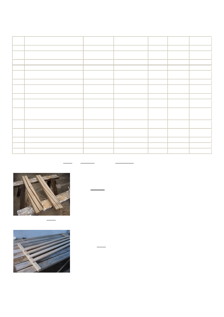
Lay the frame on its side and fix one of the plywood panels [e] to the rails [c] as shown in the picture.
Flip the unit over and repeat with the other panel on the other side.
Step 8:
Measure cut and fit the two side plywood panels [g].
Step 9:
Screw the lid support [h] to the top rear rail [c] but first, position the lid support [h]
so that it is 18mm (3/4") above the top of the top rear rail [c] which is the thickness
of the lid [i].
Pre-drill all the screw holes in the lid support [h].
Step 10:
Cut and position the lid [i].
Ensure that the lid has at least 6mm (1/4") clearance on each side so that it can
open and shut without grinding against anything.
NOTE: This complete plan-set can be purchased in downloadable PDF format with more pictures free of advertising
and print friendly for only $5. For more info click here
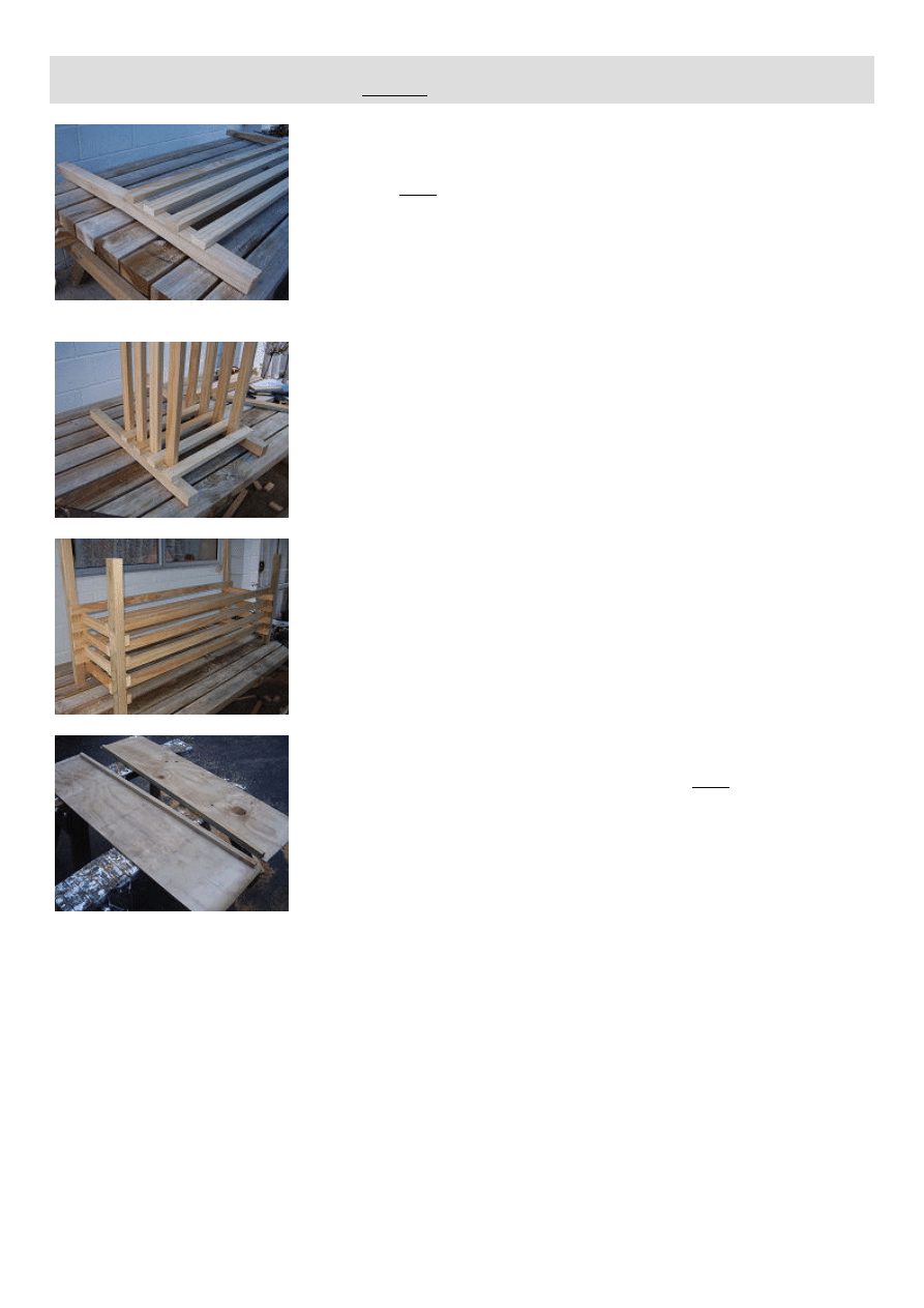
Step 11:
Fix three evenly spaced hinges to the lid [i] and the lid support [h].
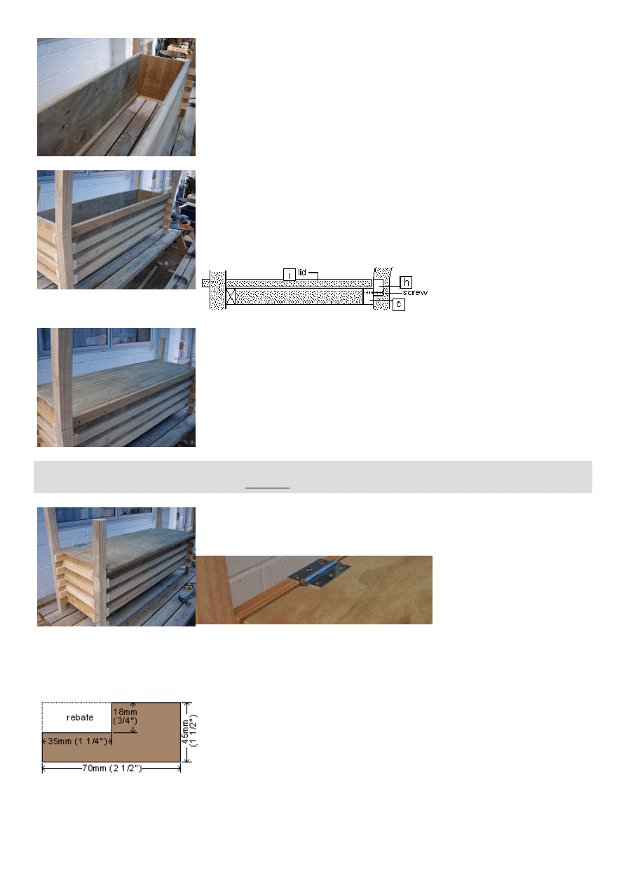
Step 12:
Cut the two back-rest rails [j] to length.
Mark the rebate on both pieces. See the drawing below.
Clamp the two pieces together, set the blade on the circular power saw to the required depth and commence ripping.
Step 13:
Unclamp the two pieces [j].
Re-set the depth on the circular power saw to the required depth for the second cut.
Make the second cut on each back-rest rail [j] thus completing the rebate.
NOTE: This complete plan-set can be purchased in downloadable PDF format with more pictures free of advertising
and print friendly for only $5. For more info click here
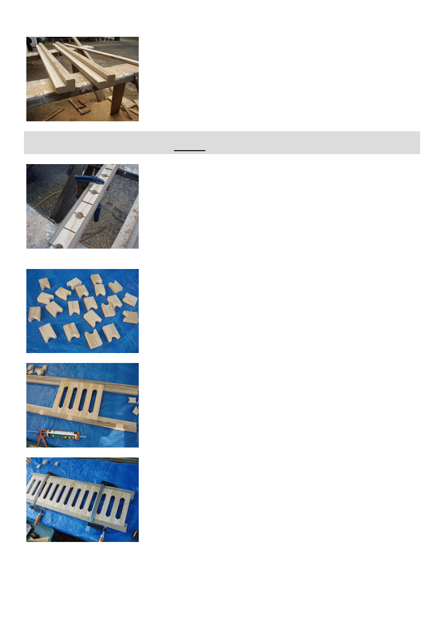
Step 14:
Make a pencil mark across a length of 40mm x 18mm (3/4" x 1 1/2') wood at 70mm
(2 1/2") intervals.
Clamp the length of wood (to be drilled) on top of another piece of spare wood. This
is so that when you drill through the top piece, it will not tear the wood when the drill
breaks through the other side of it.
The bottom (spare) piece can later be discarded.
Drill a 25mm (1") hole at every second marked line. See the picture.
Step 15:
Cut through every pencil mark with a hand saw or a chop saw if you have one..
You will end up with a lot of little pieces as shown in the picture.
A little bit of sanding at this stage will not go astray.
Step 16:
Start laying out the little decorative pieces [k] and the back slats [l] in the rebates of
the two back-rest rails [j].
Do not nail or fix at this stage, just lay them in place to see how they pan out.
Step 17:
Once you have placed all the back-rest pieces [k] and [l] so that the pattern is
centralized, (this was just a practice run) then you can remove them, add a bit of
glue to the sides of the little decorative pieces [k] and then put them all back again.
Once re-positioned, hold everything tightly together with a couple of clamps.
Step 18:
More than likely you will have to cut the end pieces to make them fit.
You can then nail all the back-rest pieces [k] and [l] to the back-rest rails [j].
Use 30mm (1 1/4") galvanized nails, pre-drill the holes into the back-rest pieces [k] and [l] and set (punch) the heads
of the nails into the wood.
Step 19:
Fit the back-rest unit in place between the top of the two rear legs [b].
Position the back-rest unit (height-wise) according to the plan or according to your
taste.
Secure with two 90mm (3 1/2") screws at each meeting.
Pre-drill the screw holes through the rear legs [b].
NOTE: This complete plan-set can be purchased in downloadable PDF format with more pictures free of advertising
and print friendly for only $5. For more info click here
Step 20:
Cut, shape and glue and screw the arm-rest supports [m] in place.
Refer to the plan for placement.
Use two 50mm (2") screws for each piece and pre-dill the arm-rest supports [m]
first.
Step 21:
Add the arm-rests after first applying a bit of glue.
Nail the arm-rests to the arm-rest supports with 50mm (2") galvanized nails. Pre-drill
the nail holes in the arm-rests and set (punch) the heads of the nails into the wood.
Step 22:
Now just cut a few boards [o] to go into the base of the boot box, and that's about it.
There is no need to nail any of the base boards [o] as they can just sit there on top
of the wood strips [f].
Wyszukiwarka
Podobne podstrony:
boot
Boot Hill Loot Tables
potting bench
Arbor Bench id 67571 Nieznany
Bench Outdoor
planter bench
Build a Garden Bench(1)
brak pliku NTLDR pliku SYSTEM brak BOOT INI naprawa MBR WinXP
Podstawy użytkowania komputera, 7 Komunikat no BOOT device
boot ini cwiczenia
Gardening Bench
Bridgewater Bench Swing lawka
Outdoor Table and Bench
planter bench plan
Classic Cedar Garden Bench
PKT Polish Koders Team • Zobacz wątek u boot krok po kroku
0 50V 2A LM10C, 0 50V 2A Bench power supply circuit diagrams, schematics, electronic projects
Boot Hill Character Record
więcej podobnych podstron