
never before, it’s becoming increasingly difficult to manage
all these sources. To make matters worse, what happens when you want to
direct multiple sources to multiple destinations, all with a single switchbox
and no
Enter Steve’s newest project: the
Steve first introduced an AVMux back in 1986 and it was an instant hit.
Now he revisits the old concept with some new ideas, chips, and remote
control schemes. We start this month with the first part of his project: the
multiplexer itself.
Along with the latest wiz-bang
cable systems comes the
question, “But is there anything worthwhile watching yet?” (See “Steve’s
Own INK” on the last page for more on this.) If you read between the lines,
though, you can find worthwhile information hidden inside even off-air TV
signals. Contained in the vertical blanking interval, our next project is
designed to ferret out such goodies as closed captions, teletext publications,
and time of day. This design contest winner should keep you busy for hours.
Our last feature should be of profound interest to anyone who does
work at home, has work-related hobbies, or does work for hire think I just
described the vast majority of our readers). Who owns the copyright on that
work you do in your home or on your own time? It’s a sticky issue in some
cases, so we found two lawyers who specialize in intellectual property to
look at recent case law and try to smooth it over for us.
In our columns, Ed continues with his large LCD panel interface by
adding some real software support. Jeff revisits computerized speech by
putting together a small, recordable audio output board that can be used for
speech and sound effects alike. Tom looks at a new processor using a super
Harvard architecture (SHARC) that sports no fewer than four address/data
buses internally. Finally, John adds a reset circuit, battery monitor, and LCD
display to his embedded controller system.
On a final note, want to mention that this is the last installment of
Russ Reiss’s “Patent Talk.” Russ has covered many diverse topics and has
done a fine job of pointing out just how much help our patent system needs if
it’s to keep up with the explosive growth of today’s technology. In his last
column, Russ looks at security-related devices, from
standpoint of both
data security and system security.
CIRCUIT CELLAR
THE COMPUTER
APPLICATIONS
JOURNAL
FOUNDER/EDITORIAL DIRECTOR
Steve Ciarcia
EDITOR-IN-CHIEF
Ken Davidson
TECHNICAL EDITOR
Michael Swartzendruber
ASSOCIATE EDITOR
Rob Rojas
ENGINEERING STAFF
Jeff Bachiochi Ed Nisley
WEST COAST EDITOR
Tom Cantrell
CONTRIBUTING EDITORS
John Dybowski Russ Reiss
NEW PRODUCTS EDITOR
Harv
Weiner
ART DIRECTOR
Lisa Ferry
GRAPHIC ARTIST
Joseph
CONTRIBUTORS:
Jon
Tim
Frank Kuechmann
Pellervo Kaskinen
Cover Illustration by Bob Schuchman
PRINTED IN THE UNITED STATES
PUBLISHER
Daniel Rodrigues
PUBLISHER’S ASSISTANT
Sue Hodge
CIRCULATION COORDINATOR
Rose
CIRCULATION ASSISTANT
Barbara
CIRCULATION CONSULTANT
Gregory Spitzfaden
BUSINESS MANAGER
Jeannette Walters
ADVERTISING COORDINATOR
Dan Gorsky
CIRCUIT CELLAR INK. THE COMPUTER
JOURNAL
is published
monthly by
Cellar Incorporated, 4 Park Street,
Suite 20, Vernon, CT 06066 (203)
Second
One-year (12
subscription rate U.S.A. and
$49.95. All
orders payable US
funds only, via
postal money order or
check drawn on US. bank. Direct
orders
and
related
to The Computer
Journal
P 0
7694,
NJ 08077 or call
POSTMASTER: Please send address changes The
Computer
Journal,
Dept., P.O.
7694,
NJ 06077
ASSOCIATES
NATIONAL ADVERTISING REPRESENTATIVES
NORTHEAST
SOUTHEAST
Debra Andersen
Collins
WEST COAST
Barbara Jones
7)
-ax: (617) 769-8982
MID-ATLANTIC
Barbara Best
(305) 966-3939
Fax:
(305) 985-8457
MIDWEST
Nanette Traetow
Shelley Rainey
(714) 540-3554
Fax:
(714) 540-7103
-ax: (908) 741-6823
(708)
Fax:
(708)
Hrs.
bits, parity, 1 stop
bps
HST, (203)
All programs and
in
been carefully
their
by
no warranties and assumes no
or
of any
for errors in these
or for the consequences of any such errors. Furthermore, because of
and condition of
and
of reader-assembled projects,
Cellar
INK
any
for the
and proper function of reader-assembled projects based upon or from
plans,
or
in
Cellar INK
Entire contents
1994 by
Cellar Incorporated. All
reserved
of this
publication whole or
consent from
Cellar
2
Issue
April 1994
The Computer Applications Journal
1 4
Control Your Audio/Video Connections
with the
by Steve Ciarcia
2 4
Exploring the Vertical Blanking Interval/A
Tool for
Gathering Data from your TV
by Mike
4 0
Employer Ownership of Employee and Consultant
Work Product
by Mary
Laura Butzel
4 4
Firmware Furnace
Bringing the ‘386SX Project’s
Graphic LCD Panel to Life
Ed Nisley
q
From the Bench
Build the Message Board/An Audio
Record/Playback Unit
Bachiochi
6 2
q
Silicon Update
When the SHARC Bites
Tom Can
6 8
q
Embedded Techniques
Who’s in Control?
Dybowski
Ken Davidson
Video Galore
Editor’s INK
Excerpts from
the Circuit Cellar BBS
conducted by
6
Ken Davidson
Letters to the Editor.
Steve’s Own INK
Steve Ciarcia
In the Citadel
New Product News
Advertiser’s Index
The Computer Applications Journal
Issue
April 1994
3

Let Me Interrupt You for a Moment
have just finished reading issue
and
I
have
strong feelings regarding Do-While Jones’ article (“Inter-
rupt-free Design”). Although the underlying premise
(that design decisions must be made thoughtfully, not
just because things have always been done that way) is
sound, I feel that Mr. Jones has greatly overstated his
case, perhaps for effect. There are several valid points
made in the article, but I feel that they are all but
obscured by the “over the top” rhetoric and use of
inappropriate analogies.
Mr. Jones extracts interrupt usage from the rest of
the firmware design context, and then expounds on its
inappropriateness. The creation of a design is a holistic
process, wherein all the issues have to be weighed
together and the “best” design is obtained by applying
tradeoffs. Whether or not to use an interrupt for a
particular peripheral is but one of these many tradeoffs.
His A/D conversion example makes multitudinous
(unstated) assumptions about the application at hand and
the design of the rest of the firmware. Perhaps these
assumptions are valid for the case that he had in mind,
but this is hardly justification for sweeping generaliza-
tions against interrupts. For example:
“An A/D converter satisfies neither of the two
criteria for correct use of an interrupt. Interrupts should
be used when
(1) you
can’t predict when data will be
available and (2) data must be taken from the peripheral
promptly or it will be lost. Dedicated controllers always
know when data from an A/D converter will be avail-
able. It comes at a periodic rate synchronized to a clock.
It should be no surprise that the data is available.
Furthermore, it is the program that must have the data
promptly, not the peripheral that must have the data
taken from it promptly.”
If it were true that you can always predict when data
is available from an A/D converter, why is it that they
are equipped with a “conversion done” output? For Mr.
Jones to assert that it is not the ADC that requires the
data be taken promptly, it is clear he has never had to
run an ADC in continuous conversion mode, where the
output must be captured quickly or it will be replaced by
the next sample.
Based on his background, I am sure Mr. Jones’
examples of “justified use of interrupts” don’t accurately
reflect his understanding of design issues. Consider:
.For example, the radiation-leak detector in a
nuclear power plant should be connected to an inter-
rupt....”
Here he confuses system-level design issues (i.e., the
response time) with controller-level issues (i.e., interrupt
input or not.) For all we know, the emergency detection
system could be a dedicated controller responsible for
monitoring 100 digital inputs, displaying their state on
100 indicators, and activating a horn as an alarm. In this
case, the simplest implementation is a continuous loop
that polls the inputs, reflects their state in the indicators,
and enables the horn output based on some simple logic
conditions. No need for interrupts here!
In contrast, consider a hardware/firmware design
I
recently completed. Among other peripherals is a 12-bit
dual-slope ADC taking 16.6 ms per conversion. The
ADC is not directly connected to an interrupt input, but
is polled at an interval determined by a timer interrupt.
While it would be possible to perform the same work in
the “background” processing, I have selected the method
I did because it allows me to know precisely the rate at
which the inputs are sampled. This wouldn’t be easy to
do if the polling were done in a background process.
In my experience, firmware designers are too
unwilling
to use interrupts, because (and I agree with Mr.
Jones on this point) they are more difficult to under-
stand. Unfortunately, their avoidance often results in
firmware that, as a whole, is more complex, harder to
debug, and harder still to maintain.
The points to remember, with my annotations:
@“Knowing how to recognize situations when it is
wise to use interrupts or to avoid them like the plague
will lead to.. .[a] design that may be cheaper, simpler, and
more reliable.” [I disagree with the assertion that the
interrupt-free design will always be the one that is
cheaper, simpler, etc.]
is always faster to poll a peripheral’s status port
to make sure it is ready and then transfer data to (or
from) the peripheral’s data port than it is to respond to an
interrupt generated by the peripheral’s status port.” [But
this is a very local consideration, that could easily be
overridden by higher-level issues.]
*“Interrupt-driven designs tend to be chaotic and
nondeterministic.
.
have to be very careful to make
sure there are no race conditions or sequences of inter-
rupts that can cause trouble.. Interrupt-free designs are
much more predictable.. The logic is simpler because
the program controls the order in which things happen.”
[There is no doubt that interrupts introduce difficulty,
and are not necessary in every case.]
should be used when they make the
design simpler
.If you were using interrupts appropri-
ately, they would solve your problems, not cause them.”
All in all, the article would have been much better if
it presented a balanced view and tried to give realistic
case histories where interrupts were and were not
Issue
April 1994
The Computer Applications Journal
INK
appropriate. As it stands, it comes across as a tirade
against interrupts, and an unconvincing one at that.
Martin Vuille
Kemptville, Ontario
And While We’re on the Subject...
I thoroughly enjoyed Do-While Jones’ article in the
February 1994 issue. Never have truer words been
written about the abuse of interrupts.
When Mr. Jones was a speaker at the Embedded
Systems Conference, I remember finding his short
biography very amusing. It described his progression
from analog designer to lecturer. The next time you talk
to him, ask Mr. Jones if he has any other loop constructs
in his family.
J. Conrad Hubert
Deus Ex
St. Paul, Minn.
Contacting Circuit Cellar
We at the
Computer Applications Journal encourage
communication between our readers and our staff, so have made
every effort to make contacting us easy. We prefer electronic
communications, but feel free to use any of the following:
Mail: Letters to the Editor may be sent to: Editor, The Computer
Applications Journal, 4 Park St., Vernon, CT 06066.
Phone: Direct all subscription inquiries to (609)
Contact our editorial offices at (203) 875-2199.
Fax: All faxes may be sent to (203)
BBS: All of our editors and regular authors frequent the Circuit
Cellar BBS and are available to answer questions. Call
(203) 871-1988 with your modem
bps,
Internet: Electronic mail may also be sent to our editors and
regular authors via the Internet. To determine a particular
person’s Internet address, use their name as it appears in
the masthead or by-line, insert a period between their first
and last names, and append
to the end.
For example, to send Internet
to Jeff Bachiochi,
address it to
For more
information, send
to
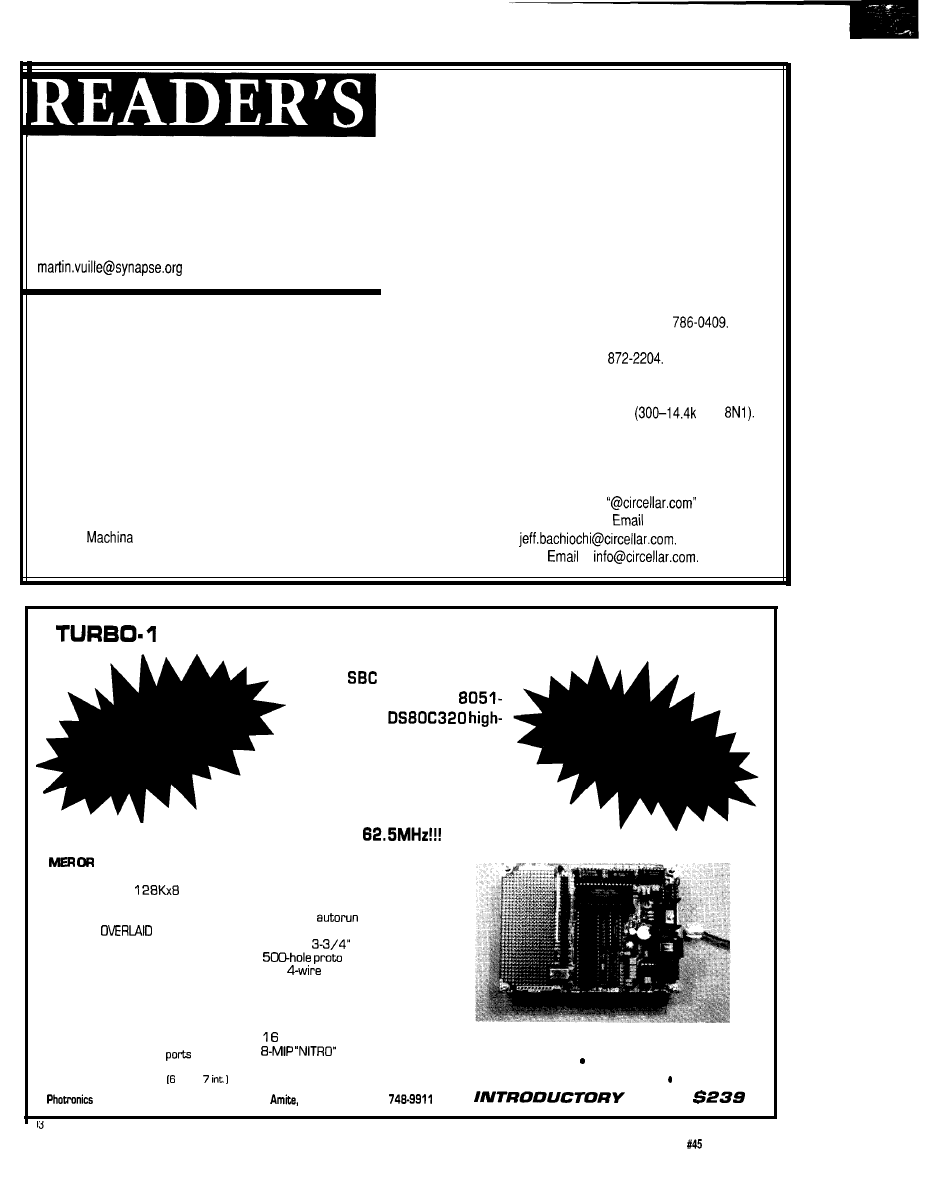
28 SINGLE BOARD BASIC DEVELOPMENT SYSTEM
T h e P h o t r o n i c s R e s e a r c h
T - 1 2 8
f e a t u r e s D a l l a s
Semiconductor’s new
compatible
speed microcontroller. With
its 2X clock speed (25 MHz]
and 3X cycle efficiency an
instruction can execute in
180ns: an 8051 e q u i v a l e n t
speed of
The T-128 board NEEDS NO
EPROM EMULATOR, PROGRAM
ERASER. With our unique
on-board memory management cir-
cuitry, a 70ns
SRAM is
configured into any nonvolatile/write
protectable combination of CODE,
DATA, or
mapping.
l
All RAM is programnied on-board
l
Dual Cell, Embedded Lithium
Backup Technology
l
Crashproof
NEW ON CHIP
FEATURES INCLUDE:
. Programmable Watchdog Timer
l
Early Warning power monitor
l
Two full-duplex serial
l
Duel data pointers
. 13 interrupt sources ext.,
A C C E L E R A T E D B A S I C - 5 2
l
Modified Basic-52 now fast
enough for new applications
l
Stack BASIC programs in
RAM and
l
8 bit ports and device-ready I/O
l
Only 5” x
includes
area
l
One
telephone cable
connects console/power
l
The powerful combination of an
accelerated Basic/Assembly
Interface easily approaches
bit capacity
l
upgrade
available soon
Research, Inc.
l
1 OS Camille St.
l
IA 70422
l
15041
With assembler, editor, terminal emulator, utilities
1 year warranty Free technical
support
Manuals and power adapter included
Ready to
Run!
PRICE
The Computer Applications Journal
Issue
April 1994
7
Edited by Harv Weiner
SERIAL LINE MONITOR
Paladin Software has announced a new version of
(formerly
a software-based asynchronous communi-
cations debugging, data capture, and analysis tool.
allows a user to apply capture, display, and search tools to
ordinarily invisible serial transmissions and provides a
effective alternative to expensive hardware-based line monitors.
includes context-sensitive Hypertext with direct
links to program setup fields,
user-alterable
multitasking window displays, oscilloscope-like signal event
tracing, an integrated font map editor, and PostScript file
exportation (EPS, PRN, TXT, or binary files of logged data for
printing or importing into reports). All data and signal events are
timestamped to the microsecond. A log capacity of 64 mega-
bytes is provided and a RAM buffer of up to 384K bytes allows logging to disk at any time.
supports all COM ports and UART formats. Any port or interrupt level may be used and two ports
can share the same interrupt line. All possible baud rates supported by the hardware are available and automatic
nearest true baud rate adjustment is used. All combinations of word length, parity, stop bits, and output control lines
are supported.
offers a convenient carrying case complete with storage space for the manual, cable, and connectors.
A tutorial answers common questions and helps users get started with a minimum amount of reading.
sells for $349.
Paladin Software, Inc.
l
3945 Kenosha Ave.
l
San Diego, CA 92117 (619) 490-0368
l
Fax: (619)
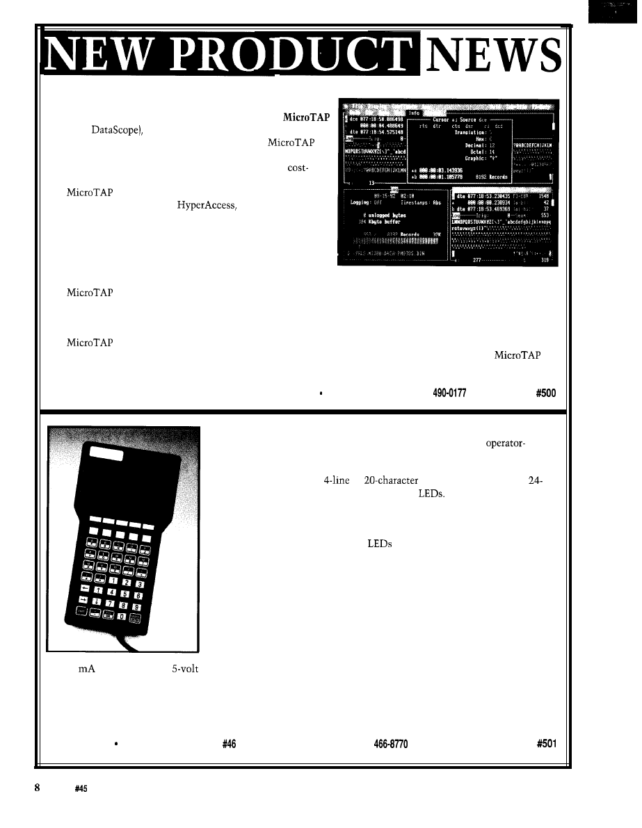
MULTIDROP INDUSTRIAL TERMINAL
The QTERM-IV Industrial Terminal is a low-cost, rugged,
interface terminal capable of multidrop operation (RS-485 or RS-422). The
terminal features either full-duplex or multidrop operation with up to 32
terminals per host port, a
by
supertwist LCD display,
or
40-key tactile keypads, and user-programmable
The QTERM-IV can be ordered with a choice of RS-232, RS-422, RS-423,
RS-485, or multidrop- interfaces. Every key can be individually programmed
to send a character or string (or to control QTERM-IV) when pressed and/or
when released. User-programmable
provide easy and flexible status
indications. Forty-eight programmable macro strings and an autoexecute string
allow for fast and easy configuration of menu systems. Up to 20K bytes of user
data can be stored in the unit.
The QTERM-IV can be configured for an application by power-on setup or
by downloading a data file. After configuration, the host can control it via
software commands. Available commands include cursor movement, mode
control, query, hardware control, macros, and user data read and write com-
mands. Custom characters can also be defined.
The QTERM-IV measures 7.7” high, 4.2” wide, and
1.3”
thick. It uses less
that 20
of current from a
supply. It can be powered through the host connector or can be ordered with a
battery option. Batteries can supply power for over 100 hours of continuous use.
The QTERM-IV sells for $295. Custom OEM labeling, including a company name, user LED labels, and one row
of function keys, are included free with any quantity purchase. Full-custom keypad graphics are also available for a
modest additional price.
QSI Corporation 2212 South West Temple
l
Salt Lake City, UT 84115
l
(801)
l
Fax: (801) 466-8792
Issue
April 1994
The Computer Applications Journal
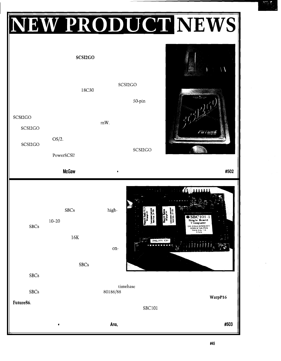
SCSI IN PCMCIA PACKAGE
True “Plug and Play” SCSI in a PCMCIA Type II format has been an-
nounced by Future Domain. The
is a credit-card-sized, 16-bit SCSI
controller. It is an easy way to add SCSI storage devices and I/O peripherals to
notebook PCs. It can also be used with any PC containing a standard PCMCIA
Type II card slot, including desktop PCs, PC workstations, and PC servers.
The controller is compatible with Card and Socket Services software. It is
capable of fast SCSI-2 data transfer rates up to 10 MB/s.
features
Future Domain’s high-performance
single-chip SCSI-2 controller with a
2K internal FIFO buffer. The three-foot interface cable is a high-quality SCSI
cable with a locking PCMCIA card connector on one end and a
SCSI-2
connector on the other.
In keeping with the power-saving philosophy of notebook PC design,
has a powered-down Sleep Mode. While operating, the controller
has a very low power requirement of only 210
is fully supported by PowerSCSI!, the universal application
interface under DOS, NetWare, and Windows. Embedded support is provided
in Windows NT and
is available in SCSI VALUEPAK and CorelSCSI Kit configura-
tions. The SCSI VALUEPAK Kit sells for $329 and includes the
card, interface cable,
software, and additional utility software.
The CorelSCSI Kit sells for $389 and contains CorelSCSI software.
Future Domain Corp.
l
2801
Ave.
l
Irvine, CA 92714 (714) 253-0400
l
Fax: (714) 253-0913
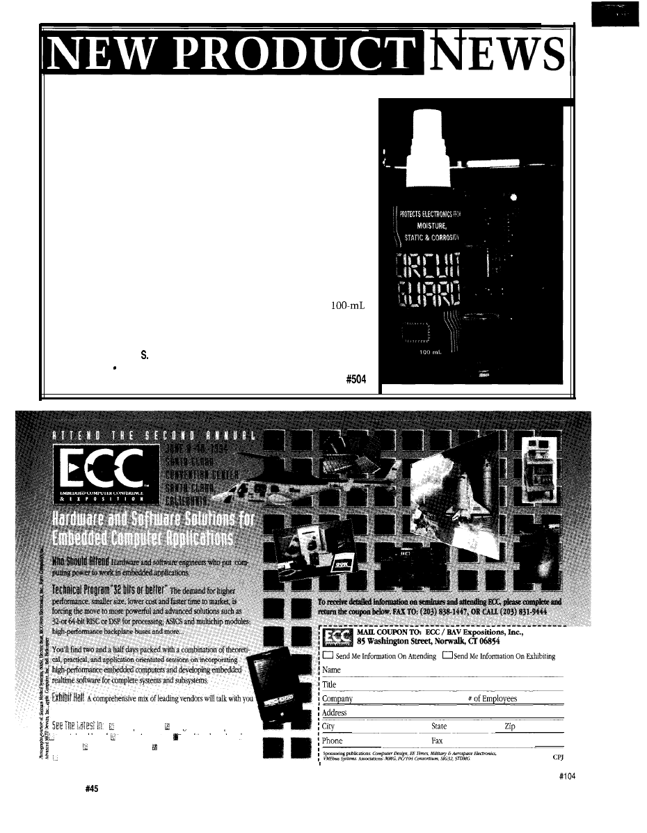
SINGLE-BOARD COMPUTER
Development Associates has announced a series of
small, cost-effective 16-bit single-board computers. The
Warp System is intended for a wide range of embedded
system applications. These
are based on the
integration CMOS V25 microcomputer and are available
with clock rates of
MHz.
The
are fully self-contained and feature all
CMOS components for low power consumption. They are
available in ROM ranges from
bytes to 512K bytes
and RAM capacities from 32K bytes to 5 12K bytes. The
CPU addresses are fully decoded, making all unused
board addresses available for external devices. System
expansion is simplified since all CPU signals have been
brought out to connector pins. The
are 3” x 3.5” and
are powered by a single 5-V power source.
The
feature reset and power-on signal conditioning, watchdog and low-voltage detection functions, two
serial ports usable to 1.2 Mbps, and eight analog comparator inputs with programmable thresholds. Additional
features include 24 parallel I/O lines, two 16-bit timers,
counter, and a programmable wait state generator.
The
are software compatible with the
family but include enhanced instructions. They are
compatible with a large number of software tools including Development Associates’ Warp16 Forth and
Both of these development environments are totally complete, providing for compiling, linking, debugging,
hex file generation, and other development tasks. The Warp System
series starts at $119. A complete line of
accessories is also available.
Development Associates 1520 South Lyon St.
l
Santa
CA 92705
l
(714) 835-9512
The Computer Applications Journal
Issue
April 1994
9
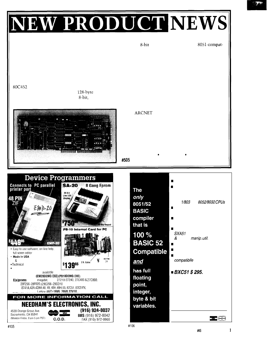
CHEMICAL CIRCUIT PROTECTOR
A newly formulated product that protects computers and electron-
ics from moisture, static, and corrosion has been announced by Circuit
Guard International. Circuit Guard
was
originally developed for the
aerospace industry to protect sensitive microcircuits from exposure to
harsh environments.
Circuit Guard forms an atmospheric barrier around electronic
components. This barrier actively encapsulates and chemically neutral-
izes all ion-transferring electrolytes (such as moisture, pollutants, salt,
and dust) which cause corrosion leading to circuit failure. Circuit Guard
will also safely discharge harmful static by neutralizing charged
particles.
The spray-on liquid is compatible with the plastics, epoxies, and
various metals used in electronic systems. Circuit Guard has a dielec-
tric strength in excess of 38,000 volts and does not alter resistive,
capacitive, or inductive circuits. It is emulsifiable in water, is nontoxic
and nonirritating to skin and eyes. Circuit Guard is available in
nonaerosol spray bottles for $19.95.
Circuit Guard International
3650 Silver-side Rd.
l
Wilmington, DE 19810
(905) 509-8752 Fax: (905) 509-4491
Internet: circuitguard@delphi.com
about
solutions to your specific
embedded and dedicated applications.
microprocessors single-board computers
peripheral boards operating systems realtime kernels and
compilers development systems CASE and debugging tools
embedded PCs __ and more...
10
Issue
April 1994
The Computer Applications Journal
REAL-TIME PC CONTROL COPROCESSOR
Modular Micro Controls has introduced the PC-452,
an 805 1 -family-compatible single-board controller
configured as a slave coprocessor for the PC/AT ISA bus.
Typical applications include network master controller,
intelligent serial port controller, I/O controller, and
peripheral controller.
The board has been developed around Intel’s
Universal Peripheral Interface microcontroller
and interfaces to the PC bus with a
bidirec-
tional FIFO. The board features two
high-current,
quasi-bidirectional I/O ports; two CMOS MPU I/O
ports; two
user DIP switches; and an
ible Y-bit UART with either RS-232C or RS-485 drivers.
The PC-452 provides a standard 805 1 local bus with two
JEDEC-compatible, 32-pin memory sites (Code and
Data). The standard configuration includes 64K of
EPROM and 32K of battery-backed SRAM.
To aid in debugging software, a status LED is
provided for each bit of MPU Port 1. An MC-bus
expansion connector and an external power supply input
connector are also provided. The expansion connector is
compatible with Modular Micro Controls’ line of
peripheral modules.
The PC-452 can be ordered with a second UART,
RS-485
interface, and Flash memory program-
mer for the 805 1 Code memory site. It comes complete
with a debugger, editor, assembler, BASIC and Forth,
serial terminal, and FIFO terminal emulators for both
Windows and DOS. The PC-452 board with standard
features and development tools sells for $499.
Modular Micro Controls, Inc.
l
411 S. Water St.
Northfield, MN 55057 (800) 832-7731 Fax: (507) 645-4342
l
1 2 Year Warranty
Support by phone
30 day Money Back Guarantee
l
FREE software upgrades
via BBS
l
Demo SW via BBS
l
2716 8
16 bit
l
Flash
(EMP-20 only))
l
Micros
87C751.752
l
GAL, PLO from NS,
(EMP-20 only)
Memory mapped variables
In-line assembly language
option
n
Compile time switch to select
805
1 or
Compatible with any RAM
or ROM memory mapping
Runs up to 50 times faster than
the MCS BASIC-52 interpreter.
Includes Binary Technology’s
cross-assembler
hex file
Extensive documentation
Tutorial included
Runs on IBM-PC/XT or
n
Compatible with all 8051 variants
508-369-9556
FAX 508-369-9549
q
Binary Technology, Inc.
P.O. Box
541
l
Carlisle, MA
01741
The Computer Applications Journal
Issue
April 1994
1
MINIATURE VIDEO CAMERA
modified version can be used with
The Optical Systems Division of
special microscope objectives for up to
Marshall Electronics has introduced a
magnification.
micro-size, high-tech, black-and-white
The camera is also infrared
CCD camera module. The
Model
sensitive which allows viewing of
can be used in such applications
nonvisible light sources such as laser
as teleconferencing, multimedia, machine
beams or heating elements in the
vision, inspection, and monitoring.
to
range. Picture elements are
The Model
can also be used
540 pels horizontally by 492 pels
as a microscope or magnifying device in
vertically and the minimum resolution
areas that were previously impossible with
is 380 TV lines. Light sensitivity is 0.5
standard cameras or inspection devices.
lux (0.05 foot-candles). The output
The complete board is smaller than a
conforms to EIA RS- 170. A CCIR
business card, yet is a full function camera
version is also available.
with built-in lens and automatic light
The module is 1.8” x 0.8” x 2.7”. It
compensation. The camera operates on 12 VDC and
uses a 3-pin modular plug for video, ground, and power.
provides a quality picture on a standard TV monitor or
The
can be run up to 1000’ with new types of
VCR. The unit can also be connected to a computer.
miniature coaxial cable.
The camera can be built into machines, assembly
This new-generation camera is considerably less
lines, robotic arms, isolated chambers, gauges, moving
costly (due to advanced LSI circuitry) than types
vehicles, and any application where remote vision can
originally used in the military, government, and
solve problems or improve the efficiency of an operation.
scientific community. The
sells for $189.
The camera comes with a wide-angle,
lens.
The lens can be focused as close as inch from an
Optical Systems Div., Marshall Electronics Inc.
object, or from 1 foot to infinity. A selection of lenses is
5649 Mesmer Ave.
l
Culver City, CA 90230
also available to suit a wide range of applications. A
(310)
l
Fax: (310) 391-8926
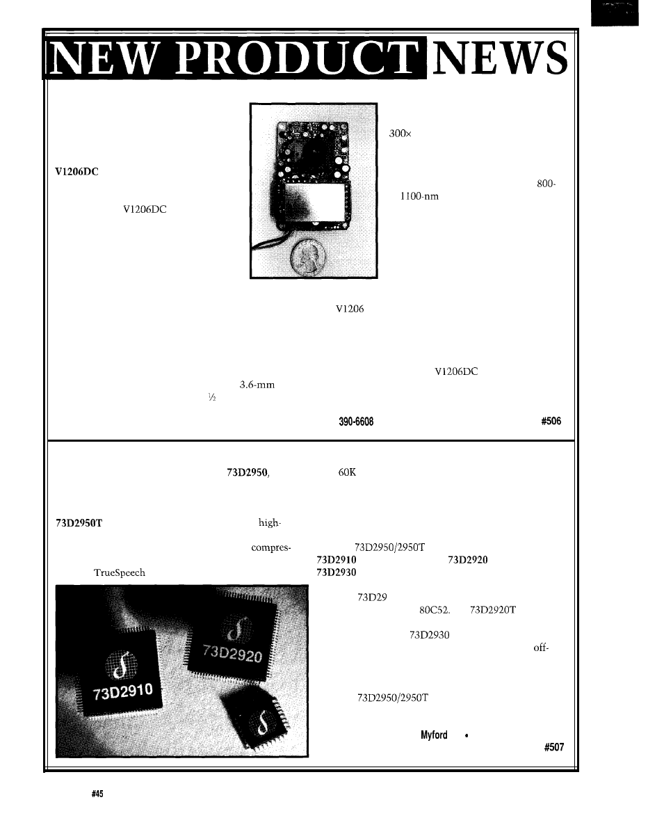
DATA/FAX/VOICE CHIP SET
Group Inc. enables a one-minute voice file to be stored in
Silicon Systems has announced the
a data/
only
bytes of memory, versus as much as 940K bytes
fax/voice chip set that integrates a transformerless Data
with other audio compression algorithms. This allows
Access Arrangement (DAA) to provide a very low power,
storage of nearly 25 minutes of audio on a single 3.5”
low-cost solution for fax modem designs. The optional
floppy disk. The algorithm has also been selected by
version enables the designer to add
Microsoft for inclusion in the next version of Microsoft
quality voice annotation or audio files to data and fax
Windows Sound Systems.
transmission using a recently licensed audio
The
includes three chips: the
sion algorithm.
microcontroller, the
DSP, and the
The
algorithm developed by the DSP
analog front end line interface circuit (AFELIC).
Smart power-down features are incorporated.
The
10 is a custom microcontroller based on
the industry-standard
The
DSP
option includes direct microphone input and direct
speaker output. The
incorporates the
transformerless DAA and provides the necessary
hook conditioning functions for connection of the chip
set to both domestic and international public switched
telephone networks.
The
data/fax/voice chip set sells in
OEM quantities for $22.00 and $29.50, respectively.
Silicon Systems
l
14351
Rd. Tustin, CA 92680
(714) 731-7110
l
Fax: (714) 669-8814
12
Issue
April 1994
The Computer Applications Journal
LIVE VIDEO IN PC WINDOW
Telebyte Technology has introduced the
Model 722
PC Workmate,
a
device that allows live video windows
to appear on a VGA display. The video window can be
user-positioned or can occupy the entire VGA screen.
This Picture-In-Picture (PIP) capability can be used for
security surveillance, to view real-time data along with
program applications, or at home performing
related tasks while watching the news or kids.
The Model 722 PC
incorporates a full multiband VHF/
UHF/CATV tuner which can receive up
to 70 channels of TV information. In
addition, the PC
has direct
video inputs for a VCR, video disc,
camcorder, or surveillance camera and
includes a built-in speaker. The unit is
suitable for any standard VGA adapter
and monitor, and delivers clear sound
with high-resolution pictures.
It is connected between the PC
system and the color display monitor.
It merges the VGA signal with the
video signal and sends the combined signal to the VGA
monitor. The video signal can come from the built-in
tuner system or from an external video source.
Logically, the PC
is transparent to the PC
system. It can be treated as a TV set that shares the
monitor with the PC system. It does not require any
software and will not affect the PC operating system.
Installation only requires moving cables. You can control
display mode, PIP position, video source, channel, and
more from the front panel of the PC
Workmate.
The PC
package is 15” x
3%” x 10%“. Model 722 is supplied with
all necessary mating cables. The unit is
available as Model 722N to support the
NTSC standard, or as Model 722P to
support the PAL standard. Model 722
PC
sells for $525 each, with
discounts for quantity.
Telebyte Technology, Inc.
270 E. Pulaski Rd.
l
Greenlawn, NY 11740
(516) 423-3232
l
Fax: (516) 385-8184
TWO PROGRAMS FOR ONE LOW PRICE!!
SUPERSKETCH & PCB II:
INTEGRATED
II SUPERSKETCH features:
MOUSE DRIVEN *SUPPORTS CGA, EGA, VGA
SVGA,
* OUTPUT TO 9 24 PIN PRINTERS, HP LASERJET&
HPGL
l
OUTPUT TO DTP PACKAGES *
PCB II ALSO HAS GERBER OUTPUT VIEWING. *
THE EASIEST TO USE CAD
R4 SYSTEMS Inc.
1111 Davis Drive, Suite 30-332
Newmarket, Ontario
(905) 898-0665
fax (905) 836-0274
ALL PRICES ARE IN US FUNDS, PLEASE INCLUDE $7
Your guide to the
of mobile and intelligent robots.
With each new issue you’ll descend into Antarctic volcanoes, design silicon
ants, build solar-powered photovores and compete with automated firefight-
ers. You’ll also build the latest robot kits, review the newest books, and
receive expert guidance from master robot crafters.
Discover the fun and rewards of
machines. Free
com-
puters from the desktop and start them
about the
Order
190 $14.95 US/Canada/Mexico $29.95 World-Wide
Mobile Robots
Ins
MIT Al researchers Anita
to
lynn and Joseph Jones provide everything you
need to start building robots today. Learn basic electrical and mechanical
theory, microcomputer Interfacing, and software techniques such as
sumption. Mobile Robots won’t leave you high and dry with a lot of theory.
You’ll find plans, schematics, and a rich array of resources. Start with a sim-
ple non-microprocessor robot and work up to a fully-intelligent machine.
No other robot book is as detailed.
Order
Muscle Wire
Motion Without Motors!
lmaaine havina
own six-leaaed walkina machine
of
the most rugged-desktop
The Muscle Wire kit provides a
Shape Memory Wire-thin filaments that contract when a voltage is applied.
Muscle Wire is strong-wires the thickness of a human hair can lift copper
pennies! In addition to sophisticated walking machines, the Muscle Wire
project manual contains dozens of projects: from airplane launcher’s to ani-
mated
Projects for all ages and abilities.
Order
$59.95.
Call Today
Mastercard/Visa Accepted
POB 458, Peterborough NH 03458
603.924.6079 (voice) 603.924.9441 (fax)
Internet orders accepted:
107
The Computer Applications Journal
Issue
April 1994
1 3

‘URES
Control Your Audio/Video
Connections with the
AVMux
Control Your
Audio/Video
Steve Ciarcia
Exploring the Vertical
Blanking Interval
Employer Ownership of
with the
AVMux
Employee and Consultant
Work Product
bout nine years
ago, the concept of
an entertainment
(a.k.a., media) room
became a heavy topic in audiophile
and videophile circles.
rooms lost
their pool tables and pinball machines,
and relatives expecting the same (free)
svare bedroom were shown the Yellow
Pages under “motels.” Home builders
who had just come to grips with
jamming jacuzzis into the master
bedroom closet now had to come up
with a home theater to entice the
sophisticated home buyer.
Aside from the physical room
itself, the reality of a dedicated
entertainment space was primarily a
matter of assembling the components.
Virtually all of the equipment (projec-
tion television, CD player, laserdisc,
VCR, amps, etc.] was available off the
shelf, but implementing the physical
connections among the components
presented a problem.
Virtually all of the equipment of
sufficient quality for this purpose also
had singular applications. Good stereo
systems (“good” is interpreted as
meaning audiophile quality) consisted
of individual modules such as a tuner,
preamplifier, amplifier, CD player,
sound field processor, subwoofer
amplifier, DAT player, and so forth. It
was not uncommon to have to use
eight or ten of these electronic sub-
systems to create the proper sound and
video atmosphere in a true entertain-
ment room.
The unfortunate truth back then
was that while the concept of coordi-
nated media was easily understood, an
adequate means for channeling the
audio and video signals among all
14
Issue
April 1994
The Computer Applications Journal
these subsystems
that would
ultimately result
in the desired
effect was no
small task. In
fact, it was a
wiring maze. To
ease the wiring
congestion and
simplify overall
interconnection, I
designed a
combination 8x8
audio and video
multiplexer.
Photo l-The finished
and hand-held control unit add both sophistication and class any home
The AVMux, as I called it, was
(and is) exactly as the name implies. It
was an electronic cross-matrix of
switches which channels specific
inputs to designated outputs. the
case of an 8x8 multiplexer, the inputs
to it (commonly called the
come from the outputs of the various
signal-generating subsystems, such as
CD players, VCRs, laserdisc, tape
recorders, and so forth (subsystems
with both audio and video outputs
would use the appropriate audio or
video input side of the multiplexer).
Similarly, the output side of the
AVMux was connected to the inputs of
various other system components
(called tos): preamplifier, amplifiers,
surround decoder, soundfield decoder,
tape recorders, and so forth.
Using the AVMux and a series of
push-button settings like “From 2 to
6 “From 3 to 5,” and “From 3 to
would, for example, channel the
7,”
laserdisc into a system combination of
the preamp, amplifier, and subwoofer
amp (we presume speakers are always
connected to a particular amplifier). To
change the source from the laserdisc to
the CD player, we might enter “From
to 6” on the control. This “erases”
the “From 2 to 6” connection and
replaces it with “From 1 to 6” instead.
A SOLUTION NOW LACKING
A PROBLEM?
Nine years later, the scenario is
quite different. Consumer audio and
video equipment have made signifi-
cant advances such that the borderline
between true “audiophile” and
end” consumer quality is fuzzy at best.
To obtain superb sound and video in
the past, the only solution was to use
more expensive modules and exter-
nally connect things through an elec-
tronic multiplexer like the AVMux.
the equivalent separate boxes..
Today, stereo manufacturers have
succeeded in providing some real
power and quality in a single enclo-
sure. It is not hard to find the equiva-
lent of the tuner, preamplifier, two
stereo amplifiers, subwoofer
amplifier, a Pro-Logic surround
decoder, and a dedicated audio/video
multiplexer in one enclosure. A
Mitsubishi unit I looked at recently
included all this for $1400. When I
compare this to the $10,000 I spent on
The greatest
attribute of
today’s “inte-
grated compo-
nent” single-box
stereos [provided
it is of sufficient
quality) is that
they contain an
integral dedicated
multiplexer. With
external input
designations like
VCR2,
TAPE 1, TAPE2,
CD,
and
AUX2 (remember, the tuner and
surround decoder are already in the
box, so they don’t need external
inputs), a simple push button or
remote tells the internal multiplexer
(frequently a relay) to channel the
appropriate input through the preamp
into the surround decoder and amplifi-
ers. The outputs of this system are
usually just speaker terminals and the
direct video from the designated
source. This video goes to a separate
monitor such as a projection TV.
multiplexer is always a Nxl and the
Depending upon the brand and the
cost, you can find a variety of input/
output configurations. Because they
have a dedicated avvlication. the audio
Basic serial-controlled AVMux
Video
Audio
Expanded multi mode controlled AVMux
optional
Keypad unit
with LED connection
A
u
d
i
o
16
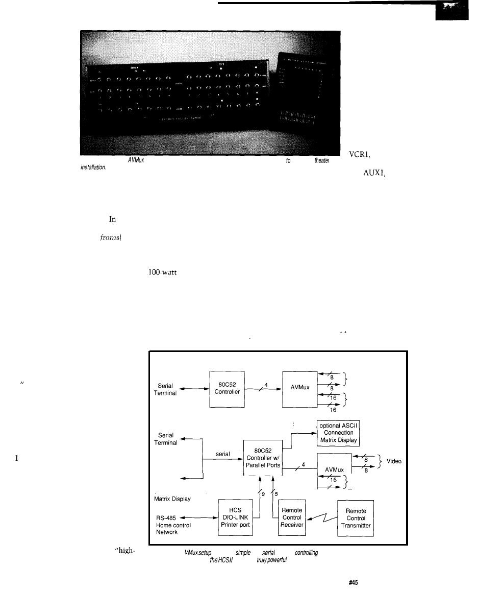
Figure l--The
A
can be
as
as a
terminal
it, or as complex as using wireless
controls, user displays, and
to make a
system.
The Computer Applications Journal
Issue
April 1994
15
Optional
Audio 1 amp
Video Amp
video rarely more than a
4x1 or 4x2.
The Nxl
audio configuration is
because all the amplifi-
ers are in the one box.
Any sound created in the
system has to be ampli-
fied by this box and all
speakers are wired to it.
If there are eight audio
inputs and only a single
output that goes to the
amps, then we have an
8x1 audio mux. Simi-
larly, since this inte-
grated system does not
incorporate its own
monitor, the manufac-
turers facilitate an
external connection
through the mux. With four video
sources and two outputs, we have a
4x2 video mux equivalent.
Vi&o
Inputs
OUT 1
OUT 8
Amp
P W R
8
Outputs
Circuit Cellar A
uses a pair of chips (one from Analog Devices and the other from Maxim) designed specifically for
doing audio and video multiplexing.
channel to 120 W per channel, or,
using the same CD player, channel its
output to a different set of speakers.
OK, enough beating around the
bush. If you want to put together an
entertainment room and you are on a
limited budget, these integrated
systems are the only way to go. One
hundred watts channeled through
efficient speakers can sound quite good
in any room.
While the integrated system has
greatly reduced the introductory cost
of an entertainment room and satisfied
bottom-up multiplexer execution to a
great extent, it has done little for
applications that don’t fit the “mold.”
right elements, it didn’t have any-
where enough power and its internal
switch multiplexer (or that on virtu-
ally any integrated unit) was far too
limited for the I/O selection I have.
The problem comes when you
want to do something that is not part
of the basic box. The instant you want
to connect three video inputs where
you only have two available, change
the front surround speaker power
output capability from 20 W per
As you might already have
guessed, very little that I do fits any
“mold.” Let me explain.
Recently I decided to revamp our
entertainment room. I thought of
using an integrated surround system
like those I described, but even the
350-W Mitsubishi unit didn’t quite fit
the bill. While it contained all the
In all truth, if I didn’t already have
all the amplifiers and many of the
subsystem components, I might would
have changed the rules to fit the
solution, but the disparity in perfor-
mance was still there. My attitude
toward surround sound movies is to
create an environment as close to the
pictured event as possible. When we
watch Top Gun, only the lack of
exhaust fumes and salt spray keeps
you from actually believing you are on
a carrier deck. To achieve this sound
envelope requires considerably more
than 5 W through a 6” x 9” oval TV
speaker. In my opinion, it also takes
more than the 300-400 watts available
from the current top-of-the-line
integrated units.
Photo
the circuit isn’t complex, wiring the
can be a major task since the cab/es must be
shielded.
My entertainment room technique
involves using separate modules
(preamp, surround decoder, etc.)
instead of the integrated unit. The fact
that a stand-alone surround decoder/
sound field processor has all its signal
outputs available, gives me the option
of using any size amplifiers I want.
Being brief, let me just say that I’m
using about 1200 watts on the dozen
speakers comprising the surround
system. Included among them is a pair
of 200-W subwoofers that guarantee
you don’t miss an F-14 fly by.
1 6
Issue
April 1994
The Computer Applications Journal
What finally convinced me to
Take away all the sound effects
redesign and further employ an
processing, decoding, and electronic
external
was the
signal manipulation and true sound
tion of dual systems. I’m sure you’ve
quality of any stereo is simply an
heard the saying, “If it ain’t broke,
audio source, amplifier, and a pair of
don’t fix it!” Well, that can apply to
speakers. In my opinion, the sound
stereo systems as well.
produced by a pair of B&W 808
ANALOG
INPUT/OUTPUT
SIN
1
SERIAL DATA IN
ANALOG
OUTPUTS/
INPUTS
BUSSED CLOCK
SERIAL
LINES
DATA
TO NEXT
STAGES
16 16 ARRAY OF SWITCHES,
LATCHES AND SHIFT REGISTER
CELLS (ONLY TWO LOCATIONS
ARE SHOWN FOR CLARITY)
DGND
DGND
SERIAL
DATA
FROM
PRIOR
STAGES
BUSSEDCLOCK
LINES
I
Y15
ANALOG
SWITCH
SHIFT
REGISTER
CELL
IN2 IN3 IN4 IN5 IN6 IN7
l-OF-8 OUTPUT
BUFFERS
EDGE/LEVEL
REGISTERS
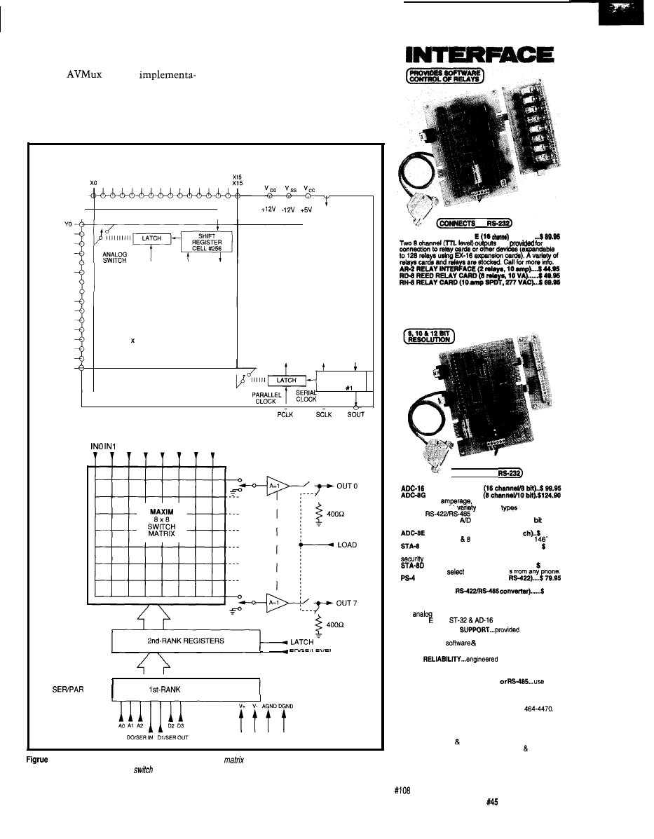
3-The Analog Devices AD75019 (top) is a 16x16 switch
idea/ for use
Maxim MAX456 (bottom) is an 8x8
meant for
video.
in audio applications
while
the
RELAY
TO
AR-10 RELAY INTERFACE
16
. . . . . . . . . . . .
are
ANALOG
T O
DIGITAL
( C
ONNECTS
TO
AID CONVERTER*
AID CONVERTER*
Input voltage,
pressure. energy “saga,
joysticks and a wide
of other
of analog
signals.
available (lengths to 4.W).
Call for info on other
configurations and 12
converters (terminal block and cable sold separately).
TEMPERATURE INTERFACE’ (8
139.95
Includes term. block
temp. sensors (-40’ to
F).
DIGITAL INTERFACE* (8 channel) . . . . . . . . .
99.95
Input on/off status of relays, switches, HVAC equipment,
devices, smoke detectors, and other devices.
TOUCH TONE INTERFACE’................ 134.90
Allows callers to
control functions from any
hone.
PORT SELECTOR (4 channels
Converts an RS-232 port into 4 selectable RS-422 ports.
CO-485 (RS-232 to
44.95
l
EXPANDABLE...expand your interface to control and
monitor up to 512 relays, up to 576 digital inputs, up to
126
the PS-4.
inputs or up to 126 temperature inputs using
X-16.
expansion cards.
FULL TECHNICAL
over the
telephone by our staff. Technical reference&disk
including test
programming examples in
Basic, C and assembly are provided with each order.
HIGH
for continuous 24
hour industrial applications with 10 years of proven
performance in the energy management field.
CONNECTS TO RS-232, RS-422
with
IBM and compatibles. Mac and most computers. All
standard baud rates and protocols (50 to 19.200 baud).
Use our 800 number to order FREE INFORMATION
PACKET. Technical information (614)
24 HOUR ORDER LINE (800) 842-7714
Visa-Mastercard-American Express-COD
International Domestic FAX (614) 464-9556
Use for information, technical support orders.
ELECTRONIC ENERGY CONTROL, INC.
360 South Fifth Street, Suite 604
Columbus. Ohio 43215-5436
The Computer Applications Journal
Issue
April 1994
1 7
Photo
the finished
you can see controller
multiplexer electronics (center), and HCS
Reference Speakers [running at another
1200 watts) comes close to perfect
audio. I like classical music straight,
while rock music seems better with all
the effects. That means I have one
system configuration for classical and
a completely different one for rock.
Keeping a dual redundant system
like this requires a sophisticated
multiplexer to allow a common set of
AV sources to be routed among all
input combinations.
A SIMPLE MUX DESIGN WITH
MANY OPTIONS
The new AVMux has improved
performance primarily because it uses
newer technology. Like the original
unit, this is an 8x8 stereo audio and
8x8 video multiplexer. Unlike its
predecessor, however, this mux allows
the user to select independent or
coordinated control of the audio and
video sections. You can have eight
audio sources with only three corre-
sponding video signals and still use the
other five video inputs for unrelated
activities. Audio and video channels
can be routed independently.
Due to its particular architecture,
which allows independent audio and
video operation, you can choose to
make just a video-only or audio-only
multiplexer. Control is realized with
an
microcontroller which
allows considerable expansion options.
As outlined in Figure 1, the new
Circuit Cellar AVMux can operate
through simple, direct, serial RS-232
control; operate with a wireless
infrared remote control; operate with a
hand-held keypad and LED connection
matrix display; display an ASCII list of
connected points during operation; and
allow network connection (using a
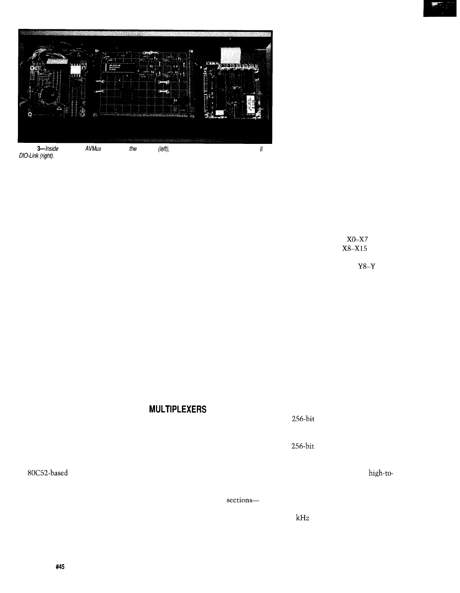
DIO-Link) with functional control
provided by the Circuit Cellar HCS II.
As you can see, this is a long list
of functions. It also incorporates
features that involve considerably
more software than I cared to write. To
finish in a reasonable time, I drafted
Jeff Bachiochi to help. I’m glad I did
and I’d further have to say that this
new AVMux has as many features as it
does because of his added expertise.
Since we worked together, Jeff will be
covering certain AVMux aspects in his
column as well.
For this month, I’ll describe the
basic AVMux components and the
controller design. Next month, Jeff
will fill in more on how the software
works, with particular emphasis on
the remote keypad/LED connection
matrix unit. I’ll conclude next month
with the wireless remote control
interface specifics.
NEW SINGLE-CHIP
Any rational person would not
even attempt to make an 8x8 multi-
plexer if it were not for the availability
of some new highly integrated multi-
plexer chips from Analog Devices and
Maxim. The configuration of the basic
AVMux using these chips is outlined
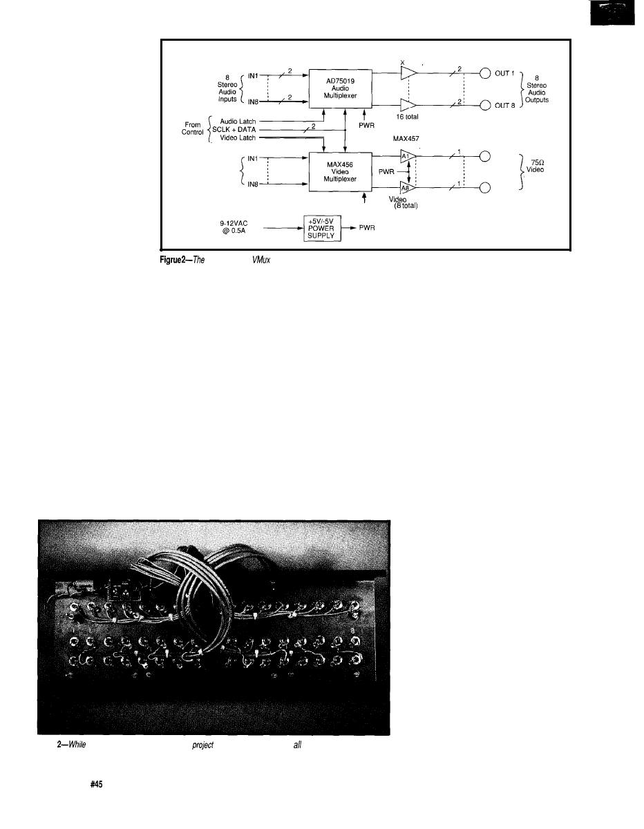
in Figure 2. Regardless of all the other
optional features, this basic circuit
stays the same. The two
audio and video-are also divisible and
you could build each separately.
The audio multiplexer is the
simpler of the two, both in concept
and construction. Employing an
Analog Devices CMOS AD75019
16x16 crosspoint switch array (its
functional block diagram is in Figure
3) allows the complete circuit to be
fabricated with just that single chip.
Unlike its video companion, an
8x8 stereo audio multiplexer involves
switching 16 signals (8 left channel
and 8 right channel). I chose the
AD75019 specifically so I would not
have to use two 8x8 devices. The
AD75019 contains 256 analog
switches in a 16x16 array. Any of the
X or Y pins may serve as inputs or
outputs. Any of the X pins can be
programmed to connect to any Y pins
and vice versa. The switches allow
amplitudes up to the supply voltages
and have a typical resistance of 150
ohms.
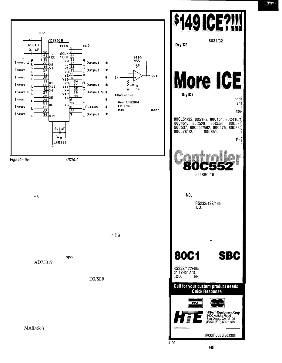
Figure 4 shows the actual circuit
connections. To keep things simple,
we designated all X pins as inputs and
all Y pins as outputs:
are right
channel inputs l-8,
are left
channel inputs l-8, YO-Y7 are right
channel outputs l-8, and
15 are
left channel outputs l-8. I know that
chip designations use “0” instead of
“1” as the first signal line, but try to
tell someone unfamiliar with electron-
ics that and you’ll get a blank stare.
Zero to seven is for the builder and one
to eight is for the user.
Connecting input X2 to output Y7
is accomplished by closing the
crosspoint switch at their intersection.
Each of the 256 crosspoint switches is
controlled by a shift register cell. If the
cell contains a 0, the switch is open. If
the cell contains a 1, the switch is
closed. The contents of all the cells,
describing the crosspoint matrix map,
is a
data packet.
The data is loaded serially via the
SIN input (DATA) and clocked into
the
shift register via SCLK
(CLK). When all 256 bits have been
entered, data is transferred in parallel
to the switch latches on the
low leading edge transition of PCLK
(ALD). One caution to note here: the
serial shift register in the AD75019 is
dynamic and the minimum clock rate
is 20
(the maximum rate is 5
MHz). With a high-level language
controller, an assembly language
routine is often used to send data to
18
Issue
April 1994
The Computer Applications Journal
0
-1
u c c
SIN
P 1 . 3
DATA P1.O
CLK P1.l
x0
Y8
1
2
x9
2
3
x2
x10
O u t p u t
3
R
4
4
Xl2
R
6
x13
Y13
R
Output 6
R
7
x14
R
R
8
x7
Y14
7
Y7
Y15
R
8
DGND USS
4 3
4
.
0 -5u
Voltage
F o l l o w e r B u f f e r
e t c .
b e a d d e d t o
of the outputs shown.
actual
connections to the
are numbered l-8 rather than O-7 to make it easier on the user.
this chip. Once programmed, however,
operation is static and the switches
stay programmed for as long as the
power is on.
One final note on this chip. When
powered on V, the AD75019 has a
typical switch resistance of 300 ohms.
Many applications may be unaffected
by this added resistance and you can
use the circuit as is. If you are unsure
or desire extra output protection, add
the voltage follower buffer amplifier to
each output channel (16 amps total) as
noted in the schematic.
A NEW MAXIM MULTIPLEXER
If you look closely at the
sheet on the
you’ll note that
it has a switch frequency response of
20 MHz. While I could have used it for
both sections, I opted to use a chip
specifically designed for video.
I decided to make the AVMux
video section using the new Maxim
MAX456 CMOS 8x8 crosspoint switch
(functional block diagram in Figure 3)
specifically designed for video. It
contains a similar register, latch, and
switch arrangement as the audio mux,
but the
connection logic
prohibits illegal switch connections.
The MAX456 is an 8x8 matrix, and
there are indeed 64 separate switches,
but in video applications, not all
crosspoint connections are allowed.
Video outputs should not be tied
together, for example.
In the MAX456, each output
connection command is thought of as
a combination of the binary address of
the selected l-of-8 inputs and data
such as whether the buffer is on, off, or
grounded. This data combination
results in a
value for each output
channel. To program 8 channels,
therefore, only requires 32 bits.
The MAX456 is unique in that it
can load this switch register data by
either parallel or serial means. To keep
programming consistency, I chose the
latter. The 32 bits are applied to the
IN (DATA) line as the l WR
(CLK) line is clocked (these are the
same two lines that are connected to
the audio mux). At its conclusion, the
data is latched on a high-to-low
leading-edge transition of the LATCH
pin (VLD). Using common data and
clock control lines with separate video
load (VLD) and audio load (ALD)
allows just four control lines to control
the whole AVMux.
Yes, that’s right! HTE has dropped the
price of it’s popular
Enhanced
from $269 to $149. Now you
can’t afford to be without one! This
ICE performs single step, real-time
execute to breakpoint, disassembly
and more. 8K user code space,
expandable to 32K. Order yours today!
Our
Plus has so many features
the price is unbelievable. 48K of user
space,
real-time
execution,
expandability to nearly all of the 805’
family processors.
We are
supporting pods for the 803112, 8751
a n d
W i t h p o d !
priced at only $149, going to a different
higher integration processor is easy.
and base unit are just $446 complete
At $149, our
OEM board has
the price and features you need right
now! It’s an 8051 core processor with an
eight channel, IO-bit A/D, two PWM
outputs, capture/compare registers, 16
digital
one RS232 serial port, four
JEDEC memory sockets. Add options like
t w o m o r e
ports, 24
more digital
real-time clock, serial
EEPROM, and battery-backup for clock
and RAM. Start with the Development
board; all the peripherals and a debug
monitor for only $349. Download and
debug your code, assembly or ‘C’, right
on the SBC, then use the low-cost OEM
board of your choice for production. We
also do customs call for a free
quotation.
88
MEW! Starting at only $249. Two serial
Parallel, expand to 16
8 ch. 12 bit D/A, Keybd,
Relay
more. Call for details!
ment
(619) 566-l 892
70662.1241
The Computer Applications Journal
Issue
April 1994
19
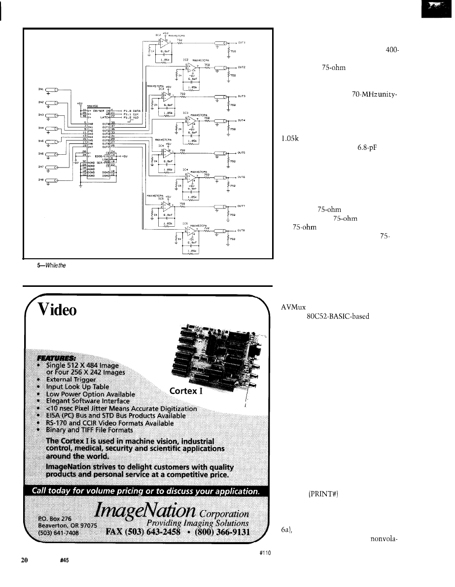
Figure
circuitry around the MAX456 video mux is simple, having to use shielded cable complicates
wiring. The MAX457 video amps are used for impedance matching.
Frame Grabber
l
$495 Including Software with “C” Library
l
Half Slot Card for Compact Applications
l
Real Time Imaging with Display Output
l
8 Bit (256 Gray Levels)
One additional note on the
MAX456. While it does have internal
video buffers, they can only drive
ohm loads. Since most video applica-
tions require
impedance,
additional external buffer amplifiers
have to be added. The dual-amp
MAX457, which has a
gain bandwidth, is the perfect choice.
As connected in Figure 5, the MAX457
is configured for a closed-loop gain of
2. The gain selection resistor is set at
instead of I k to make up for
open-loop gain loss. The
capacitor helps eliminate phase delay
at high frequencies.
We have to be careful to properly
match the cable impedances even in a
hand-wired prototype. This particular
circuit allows us to drive a doubly
terminated
line. The combina-
tion of the series
resistor and
the
termination at the output
connector produces a low-noise
ohm external connection with the
appearance of unity-gain amplification.
A FAMILIAR CONTROLLER FOR
THE AVMUX
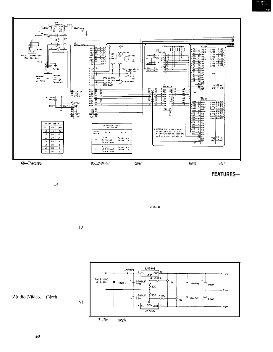
As I mentioned, it takes just 4
wires from the controller to the
chips to do everything. Figure
6b is an
microcontroller circuit which is more
than adequate for the task. Together,
they represent the configuration
outlined in Figure 1. I used a
Micromint RTC52 and RTCIO as the
controller rather than spending the
time and effort to build one. At the
price I get them, it wasn’t a hard
choice.
We chose to use BASIC (with
assembly language calls) here because
this is not a speed-intensive control
application. Using a high-level lan-
guage also expedited development and
made certain expansion options easier.
For example, since BASIC-52 supports
a serial printer output, presenting an
ASCII connection list for terminal
display was as easy as adding an
LPRINT
command.
The controller circuit has two
sections: basic controller with one
serial port and one parallel port (Figure
and the same basic configuration
with more parallel ports and
Issue
April 1994
The Computer Applications Journal
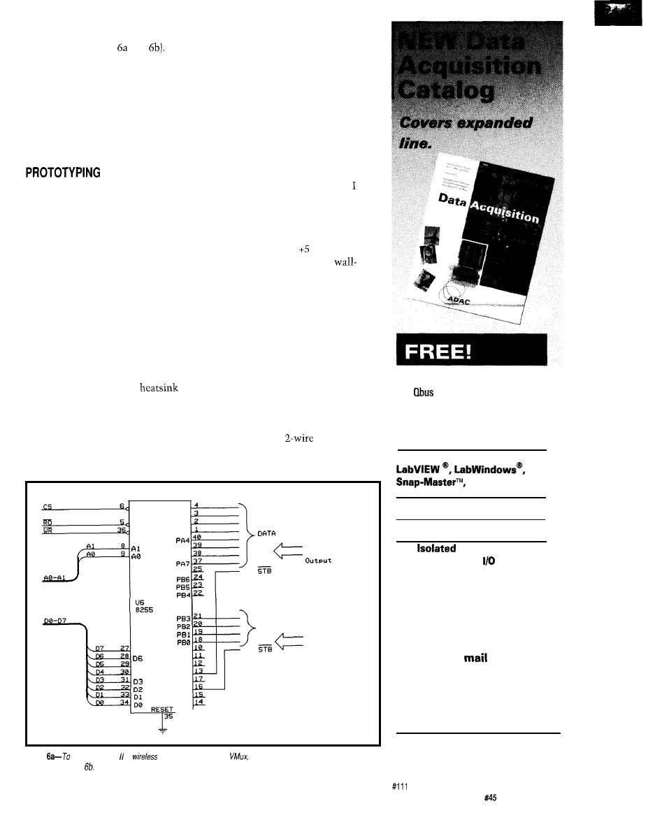
tile
memory (Figures and
Since
this circuit has been presented on
numerous occasions, I will not belabor
it. The initial circuit is suitable for
operating the AVMux through a serial
terminal. A simple connection display
and command menu prompts the user
to designate the desired From-To
connections. More later.
Success here is not just a function
of interpreting the schematic correctly.
Experience counts.
As you can see from the photos,
even though this is only a six-chip
circuit, it is a wiring nightmare. To
keep signals from radiating or picking
up the radiation from adjacent signals,
all input and output wires should be
shielded cable [now you might under-
stand the reason for doubly terminated
video buffers). I even used shielded
cable from the MAX456 to the buffer
amps. The enclosure should be metal
to serve both as an EM1 shield and as a
large noise-reducing common ground.
It can also function as the
for
your power supply.
Ordinarily, I wouldn’t discuss the
power supply in any detail. In an
application where limiting electrical
noise is critical,
I
believe it a notewor-
thy exception. First of all, I suggest
you use a linear supply only and not a
switching regulated unit. Without the
benefits of printed circuit board layout,
ground planes, single-point termina-
tion, and proper shielding (all of which
are incorporated in a production unit),
a switching power supply is just
another source of unwanted noise
(herringbone pattern on the video and
buzz in the audio).
Getting from here to there can be
an interesting journey, however.
designed my AVMux as a totally
enclosed unit. My intention was to use
one of those cheap wall-module power
sources and an internal regulator. The
AVMux operates on V and -5 V.
Unfortunately, all the cheap
modules seemed to be 2-wire output.
Since
I
couldn’t just throw in a
switching regulator or charge pump
inverter to get -5 V, I concluded that
my only option was an elaborate dual
tracking regulator with a concocted
ground. Would I have to resort to an
external power supply and pipe
everything in instead?
The answer turned out to be really
low tech. Shown in Figure 7, the
AVMux power supply is just a regu-
lated-output AC-to-DC converter. We
can get by with a
voltage source
if it is AC. The AC is then half-wave
rectified and stored as separate positive
CS
R D
W R
PA0
PA1
PA2
PA3
PA5
PA6
PB7
D 7
D 5
D 4
PC7
PC6
PC5
PC4
PC3
PC2
PC1
PC0
From
DIO
P r i n t e r
DATA
F r o m W i r e l e s s
R e m o t e C o n t r o l
Figure
add either HCS or
remote control to fhe A
an 82C.55 must be added to the core
controller in Figure
1994 120 page catalog for PC, VME,
and
data acquisition. Plus infor-
mative application notes regarding
anti-alias filtering, signal condition-
ing, and
more.
NEW
Software:
and more
NEW Low Cost l/O Boards
NEW Industrial PCs
NEW
Analog and
Digital Industrial
New from the inventors of
plug-in data acquisition.
Call, fax, or
for your
free copy today.
ADAC
American Data Acquisition Corporation
70 Tower Office Park, Woburn, MA 01801
Phone: (800) 648-6589 Fax: (617) 938-6553
The Computer Applications Journal
Issue
April 1994
21
Figure
section of the AVMux uses the same
core seen in many
projects. Connections to the outside
are done through
1 jacks
and negative supplies with a common
ground. Two three-terminal regulators
simply convert this to V and -5 V,
respectively. The one notable circuit
peculiarity is that each regulator has
been configured for voltage output
adjustment with a pot. By referencing
these pots to the opposite supplies, the
overall input-output differential
necessary for these three-terminal
regulators is reduced. Rather than a
VAC input, a 9-VAC will work just
fine. The benefit is reduced power
dissipation and a cooler AVMux box.
AVMUX OPERATION
The AVMux is designed to operate
in a variety of modes. With just the
basic serial controller, all user interac-
tion is through a terminal. When
initialized, the program displays a
connection matrix. To set a connec-
tion, the user designates whether it is
or
Answering
(A) displays the audio matrix while
or (B) displays the video matrix. The
next entries are the From and To
channel numbers, or cancel. The
program then repeats the display,
showing it with the new connections
(Jeff’s program is on the Circuit Cellar
BBS for anyone building the AVMux).
As I mentioned, by using BASIC
we have a serial printer output also
available. One program function
physically documents the entire
To connection list, by component
names (such as From ADS CD Player
To Nakamichi Preamp Aux 2 input).
This is for people who don’t want to
carry a component list to remember
channel numbers or for those who
want to have space in their stereo
cabinet and want a unique terminal
display.
EXPANDING AVMUX
THE HCS CONNECTION
Adding the 8255 PPI to the basic
controller circuit facilitates other
AVMux features. Initial operation is
through a serial ASCII terminal.
Considering that the communication
is simply the
12
characters typically
on a telephone keypad, other methods
can be employed to communicate
these characters.
The first option we thought of was
a hand-held remote that presented a
display of the connected channels on
an 8x8 LED array. It also had an
integral keypad to enter commands.
Figure
power
section creates quiet positive and negative supplies for the amplifiers from an AC
source.
22
Issue
April 1994
The Computer Applications Journal
This construction of this unit and a
description of its software will be
presented by Jeff next month.
The next brain storm we had was
to connect the AVMux so it could
work independently from, or in
conjunction with, the HCS II and the
trainable infrared MCIR-Link. The
connection is accomplished using the
DIO-Link.
Normally, the DIO-Link is used as
an 8-bit, bit-programmable I/O port on
the HCS II’s RS-485 network. The
DIO-Link can also be set to drive a
parallel printer. In this configuration,
all bits are outputs and each character
transfer is accompanied by a strobe
pulse. Character transfer timing is
programmable within the DIO-Link.
Port A and one bit of Port C are
used to receive the parallel data. The
HCS can command the AVMux by
simply sending an ASCII string, such
as
(make an Audio connection
from 3 to to the DIO-Link printer
port. It’s as easy as that.
Since we were accepting parallel
data inputs anyway, it didn’t seem
outrageous to consider an additional
source. The total
vocabu-
lary could also be represented as 12
combinations within a
code. It
shouldn’t be too hard to communicate
these codes using readily available
remote control transceiver chips. In
fact, next month I’ll demonstrate such
a wireless remote interface design.
Steve Ciarcia is an electronics engi-
neer and computer consultant with
experience in process control, digital
design, and product development. He
may be reached at
Some components of this project
may be purchased from
Pure
13109 Old Creedmoor Rd.
Raleigh, NC 27613
Phone/fax: (919) 676-4525
401 Very Useful
402 Moderately Useful
403 Not Useful
Real-Time Emulation to
Complete system for
only $895.00’
Introducing
real-time, non-instrusive in-circuit emulator
for the
family microcontrollers: a feature-filled development
system at an affordable price.
Retail for
only
l
Real-time Emulation
l
Multiple
To Cursor,
l
Operation
Step over Call, Return to Caller, etc.
l
PC-Hosted via Parallel Port
l
Search Capability in Source Code,
l
Program
Program Memory and Trace Buffer
l
deep by 24 bits wide Trace Memory
l
On-line Assembler for Patching
l
Source Level Debugging
Instruction
l
Unlimited Breakpoints
l
Support;
and
with
l
External Trigger Break with either
Optional Interchangeable Probe Cards
“AND/OR” with Breakpoints
. Comes Complete with
Macro
l
Trigger Outputs on any Address Range
Assembler, Windowed
Power
l
12 External Logic Probes
Adapter, Parallel Adapter Cable and
l
User-Selectable Internal Clock from
User’s Guide
frequencies or External Clock
l
30-day Money Back Guarantee
l
Easy-to-use windowed
l
Made in the
Call our BBS at
to download
Advanced
Corporation
Tel
14330 Midway Road,
104, Dallas. Texas 75244
Fax (214)
The Computer Applications Journal
Issue
April 1994
23

the Vertical
Blanking Interval
A Tool for Gathering Data
from your TV
use computers to
obtain information
use modems. However, there are
alternative methods, one of the more
creative of which is already present in
your house in the form of a television.
If you’re interested in a fairly accurate,
free time-source for updating computer
clocks, as well as a wealth of news and
information to read at leisure from
your terminal, you should take a
second look at TV. Not watching it,
reading it. Transcripts of many of your
favorite TV shows, and several other
interesting services are sent daily in a
part of the television picture you never
see unless your vertical hold doesn’t
work-because they are “hidden” in
the vertical blanking interval.
The
vertical blanking interval,
or
is simply the first 21 lines of each
video frame. It is the portion of the
picture not normally seen unless you
adjust the vertical hold control so the
picture rolls. Since the first nine lines
of the VBI are equalizing and vertical
sync pulses, only lines
contain
useful data.
What kinds of things are found in
the VBI? The original and still most
prevalent signals are calibration
signals such as the
Vertical Interval
Test Signal
(VITS) and
Vertical
Interval Reference Signal
(VIRS).
While important for measurement
purposes, they are otherwise fairly
boring. The more interesting signals
fall into the categories of teletext,
closed captions, and time stamps.
Teletext
is the sending of text and/
or graphic information via television.
It a subset of
videotext,
which is an
interactive two-way system usually
transmitted over telephone lines.
Because teletext is sent via TV, it is
noninteractive in nature. Teletext
systems require the receiver of the
information to use a special decoder
for display. Most teletext systems send
information in
pages
with the user
requesting a specific page to be
displayed. Because teletext systems
were developed at a time when
memory was expensive, teletext pages
are sent over and over so the decoder
need only have enough memory to
store one page. The penalty for this is
you must wait for each page after you
request it. The maximum number of
pages in most systems is 100-200.
The most common form of
teletext in the U.S. is
closed
captioning. Closed captions allow
millions of hearing impaired viewers
to enjoy TV through the use of a
decoder which displays the ASCII
captions sent in the VBI. The other
digitally encoded signal found in the
VBI of the three major networks is a
time stamp
containing the current
time and date.
In addition to describing the ways
and means of teletext signals, I will
describe the
VBI Explorer,
an 803
based project allowing you to explore
the VBI and its various data signals. It
lets you select which VBI lines to
monitor, and generates sync and video
signals for display on an oscilloscope.
Additionally, it can display raw
World
Standard Teletext
or
North American
Basic Teletext
signals and will also
decode pages and display them on a
CRT, or provide an interface for
transmission to a computer. Closed
captions can be displayed in a variety
of forms ranging from raw data to fully
decoded transcripts. Both caption and
24
Issue
April 1994
The Computer Applications Journal
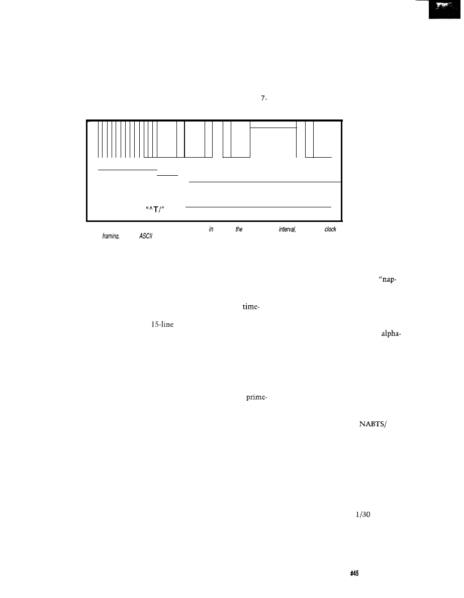
text channels are supported in closed
caption mode. Network time stamp
signals can be displayed either in raw
or decoded mode. The project can be
used either stand-alone or connected
to a computer.
The VBI Explorer is designed to be
the data gathering unit of a personal
information system. In such a system,
the VBI Explorer
feeds data to a PC.
Your favorite
network and often
local news
ranging from the slow and archaic to
the fast and complicated. The slowest
of these is the line 21 captioning
system, commonly referred to as
“closed captioning” since it is prima-
rily used to transmit captions for
hearing impaired viewers. The slow-
ness comes from sending only two
bit, odd parity characters in field 1 of
graphics and color capability is built
into the system by using a mosaic
character set. Unfortunately, most of
the WST signals are being phased out.
In 1993 cable superstation WTBS
eliminated its long-standing teletext
magazine.
The Cadillac of teletext is the
North American Basic Teletext
programs are
automatically
101010101010100001100001100110000111111111100110000
stored for reading
clock run-in
framing
at your leisure.
You can even
Bit pattern for the
two 7-bit plus odd parity ASCII Characters
have the system
“end of caption”
0 0 1 0 1 0 0 1 1 1 1 1 0 1 0 0
flag keywords and
command
control-T
I
notify you of
items of potential
Figure l--The closed captioning signal, usually found line 21
of vertical blanking
consists of a
run-in,
and two
characters
per frame.
interest. Not only
news, but programs such as Today,
Good Morning America, Nova,
Washington Week in Review, Meet the
Press, Tonight Show, and countless
others are captioned with enough clues
to detect speaker changes and generate
very readable transcripts. In addition
to gathering closed caption informa-
tion, teletext magazines can be stored
and accessed without having to wait
for the next page to roll around.
Such a concept is not new. The
M.I.T. Media Lab has been working on
this concept for many years, under
various projects such as Newsprint,
which stores captions along with an
occasional digitized picture, and
Personal Newspaper, which uses
captions along with other material to
present information customized to the
individual user.
This article assumes you have a
basic understanding of video signals,
including such concepts as fields,
frames, blanking intervals, and front
porches. If these are unfamiliar,
overviews of the video signal can be
found in many electronics magazines
as well as library books.
WHAT’S AVAILABLE?
While there are many different
teletext formats in existence, three
types are commonly found in the U.S.,
video line 21, resulting in a maximum
of 60 characters per second. Even
though the throughput is low, it is
adequate for transcription purposes.
The data stream consists of raw
text interspersed with commands
dividing the stream into two
multiplexed caption channels and two
by 32-character text channels.
However, newer decoders are capable
of receiving only one caption and one
text channel, so it appears the other
channel is being phased out. Since
1979, many programs have been closed
captioned, and the list expands each
year. All major network news shows
are captioned, as well as most
time and many PBS programs.
World System Teletext (WST) is
the medium complexity teletext
service. It received its origins from the
British ORACLE system, which has
been broadcasting since 1974 and has
undergone several revisions since then.
Data is grouped into pages of 24 lines
of 40 characters. The American
version sends only 34 characters per
VBI line as opposed to 40 in the British
system. Page size in the American
system is still 24 by 40 using a special
technique called gearing. Data may be
sent on one or more VBI lines, with
each line containing 34 7-bit, odd
parity, ASCII characters. Limited
Specification
(NABTS). There
are actually two
distinct pieces to
this system-the
actual teletext
backbone and
the data con-
tained within it.
Technically,
“NABTS” refers
only to the way
the teletext data
is structured on
the VBI line and
how packets of data are grouped. The
actual data is encoded using the North
American Presentation Level Protocol
Syntax (NAPLPS, pronounced
lips”). NAPLPS is a graphical language
which describes color, shapes, and
scaling information for the production
of a two-dimensional picture. There
really is no comparison between the
mosaic images of WST and the
geometric NAPLPS images-NAPLPS
is the hands-down winner. The price
for all this sophistication is an in-
creased difficulty of decoding and
displaying the images. The teletext
data for NABTS, like WST, can be sent
on multiple
VBI
lines, however
NABTS sends 33 characters to a line
instead of 34. At one time CBS was
sending a three VBI line
NAPLPS news, weather, and sports
magazine known as Extravision, but it
is no longer present.
Last but not least is some interest-
ing data which isn’t teletext at all!
Each of the three major networks
sends a time stamp during field one of
VBI line 20. This code consists of the
month, day, hour, minute, second, and
fraction of a second (in
second
increments). During direct network
feeds, the data is accurate to within a
second or so of the correct time (from
WWV, the national time standard),
The Computer Applications Journal
Issue
April 1994
2 5
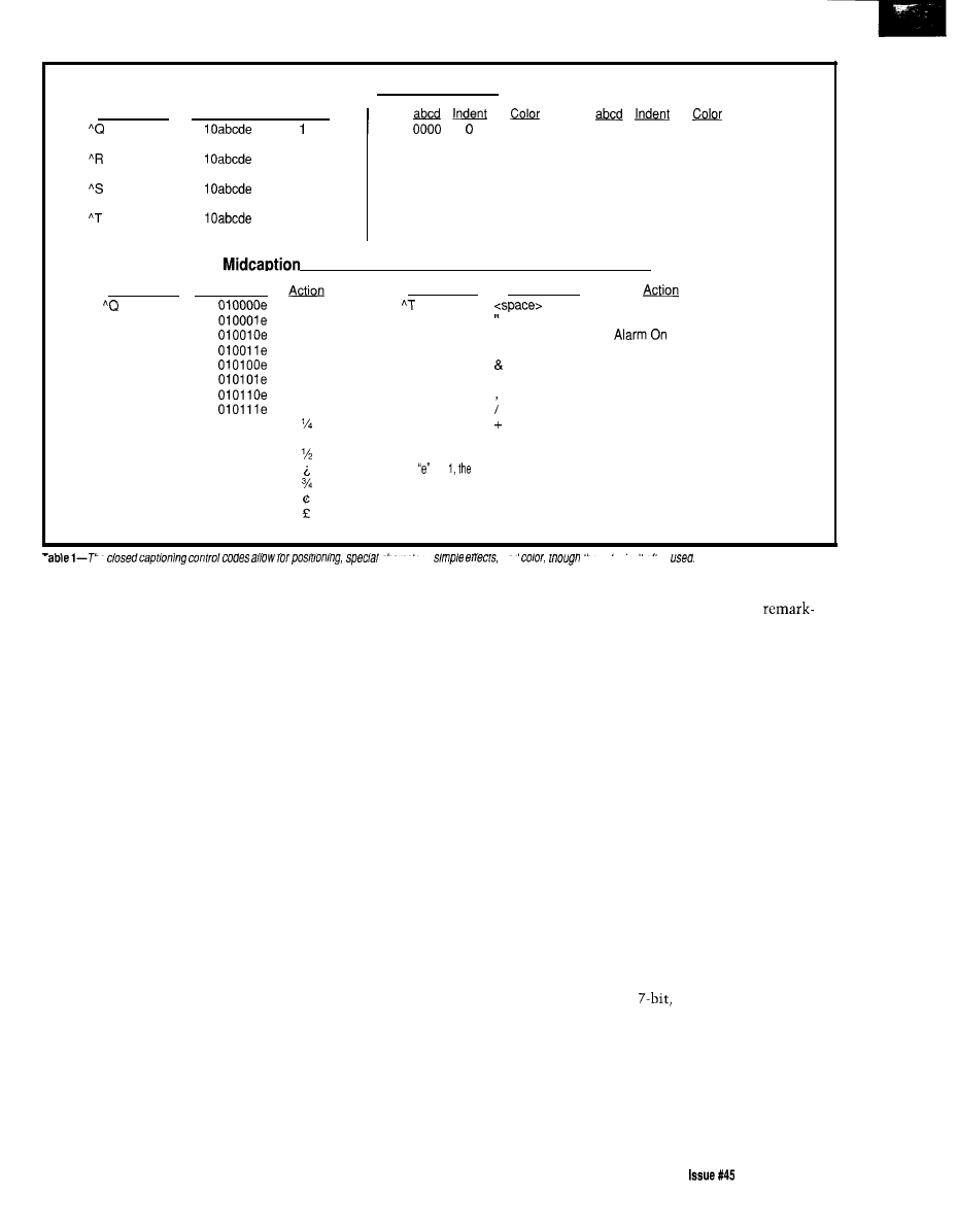
Preamble Codes
Control Char
0010001
0010001
0010010
0010010
0010011
0010011
0010100
0010100
Printina Char Row Num
White
1000
0
White
llabcde
2
3
llabcde
4
12
llabcde
13
14
llabcde
15
0001
0
Green
1001
4
White
0010
0
Blue
1010
8
White
0011
0
Cyan
1011
12
White
0100
0
Red
1100
16
White
0101
0
Yellow
1101
20
White
0110
0
Magenta
1110
24
White
0111
0
Italics
1111
28
White
Control Char
0010001
Codes, Special Characters, and Control Codes
Printina Char
Control Char
Printina Char
White
0010100
0100000
Resumecaptionloading
Green
0100010 Alarm Off
Blue
#
0100011
Cyan
%
0100101
Roll-up mode (2 rows)
Red
0100110 Roll-up mode(3 rows)
Yellow
0100111
Roll-up mode(4 rows)
Magenta
Italics
0101100 Erase Display
0101111
End of caption
0
0110000
0101011
Resumetextmodeloading
1
0110001
/(slash)
_
0101101
Carriage Return
2
0110010
3 0110011
If is
caption is underlined.
4
0110100
5
0110101
6
0110110
7
0110111 musical note
I
ne
cnaracrers,
an0
me color sn r orren
making it an ideal way to periodically
set your computer’s clock. You must
beware, however, to take it seriously
only during a nondelayed network
feed. Tape-delayed programs, as well as
other shows, will have a time stamp
containing the incorrect time. Most
times are sent as Eastern Local Time.
While the VBI Explorer explicitly
supports closed captioning, network
time stamping, WST, and NABTS, I
don’t have space to get into the details
of latter two. See the reference section
at the end of the article for more on
these and other VBI signals.
CLOSED CAPTIONS-DECODING
THE SIGNAL
One of the earliest forms of
teletext is also the most commonly
used in the United States. Closed
captions are primarily used to provide
captions for the hearing impaired,
although the system was originally
envisioned to be a complete teletext
system, with two caption and two text
channels. The second caption channel
was designed for bilingual captioning,
but this feature has gone largely
unused. Today, only the primary
caption and text channels are used. For
broadcast with a lag of five to ten
the last three years, all network prime
seconds. The system works
time programming, as well as network
ably well, though it suffers from
news, sports, and many local news-
casts have become captioned. The
popularity of captioning is likely to
increase since all televisions 13” or
larger manufactured after July 1, 1993
must be able to display captions.
There are two basic types of
captions-live or taped.
Taped cap-
tions
are produced by an editing
process prior to broadcast. A half-hour
taped program requires about 15 hours
to create the captions. Taped captions
are essentially transcripts of the
program, with text placed under or
above the person speaking. They tend
to be very accurate representations of
the spoken word. The same is not
quite as true for live captions.
For live news and sporting events,
presidential addresses and the like, the
captions must be created on the spot.
Known as real-time captioning, a
stenographer listens to the speaker and
keys in the phonetics in a manner
similar to a court reporter. A computer
program then evaluates the phonetics
and produces the text which is then
phonetically based transcription errors.
For example, “Iran” may become “I
ran” and “President Reagan” might
transcribe as “pressed I dent ray gun.”
A variation of real-time captioning
is used by many of the over 80 local
stations that caption their news.
Called electronic newsroom, the
scripted portions of the newscast sent
to the teleprompters are displayed as
captions. Unscripted portions, such as
on the scene reports, are not captioned.
For a technical description of how
closed captions work, refer to Figure 1.
Captions are normally sent on line 21
of the VBI in field 1, though they may
rarely be found in other places. The
signal consists of seven cycles of
“clock run-in,” followed by a start bit
and two
odd parity, ASCII
characters. Timing is provided by a
clock of the correct frequency which
uses the run-in bits to phase the clock
with the data. This is usually done
with a phase-locked loop, or, in the
case of the VBI explorer, with an LC
self-syncing tuned circuit.
The Computer Applications Journal
April1994 27
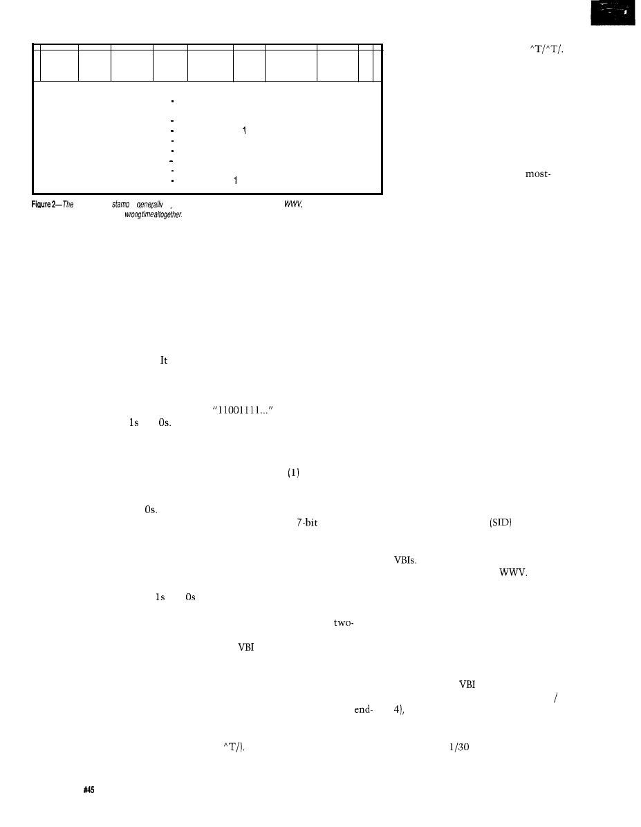
1010110 FFFFF XXXXXX QQQQ DDDDDD HHHH MMMMMM SSSSSS A
FFFF
Fraction of a second, 0 to 29.
Time is read when fraction is 2 or 3.
x x x x x x
Varies by network
QQQQ
Month of year, to 12
DDDDDD
Day of month, 1 to 31
HHHH
Hour, 0 to 12
MMMMMM Minute, 0 to 59
s s s s s s
Seconds, 0 to 59
A
AM/PM flag. if PM
network time
is
accurate to within a
second or two of
though
time-delayed
programming
may have the
The data bits as transmitted
appear slightly rounded and not
square. This is characteristic of all
teletext signals, because a square wave
has infinite bandwidth, but a video
signal has a finite bandwidth. The
compromise is to send data bits that
look more like a sine wave (actually a
cosine) than a square wave. Turning
the raw data to TTL levels involves a
technique called data slicing. is a
descriptive term since you find the
peak and trough voltages of the signal
and use a voltage set near the mid-
point of the two to feed a comparator
and slice the data into and
Data
is coded in a nonreturn to zero (NRZ)
format, which is a fancy phrase
meaning simply: If you send a 1, set
the level high and keep it high as long
as you send Is. Only change it low if
you need to send a 0. Then keep it low
as long as you are sending
Now that the analog signal is
converted to digital, the rest is easy.
Sometime during the clock run-in
sequence, the data clock will become
phased with the incoming data. The
clock then strobes the data into
memory-leaving a string of and
which can then be decoded into ASCII.
All commonly used forms of
teletext make use of a framing code
to
help authenticate the incoming data
and provide a spot to stop reading the
run-in and start decoding characters. In
the case of closed captions, bits are
read in until the framing code pattern
“01000011” is received. Up until this
time, the clock rate for closed cap-
tioned data has been 1.006976 MHz
(64x15734 Hz [the horizontal scanning
frequency]), but once the framing code
has been sent, the clock frequency
halves to become 0.503488 MHz.
Sixteen bits of data are sent at this
new rate, 8 bits for each of the two
characters, with the least-significant
bit sent first and the parity bit last.
The trick of halving the clock
frequency after the framing code is
fortunately unique to closed captions
and not found in other forms of
teletext. It is overcome in software by
using the higher clock rate and
realizing that the data bits “loll...”
will be doubly stored in memory as
At this point in the reception
process, the system has performed the
following work toward finishing the
process of converting the analog closed
captioned signal: converted the
incoming intelligence into digital data,
(2) provided a phased clock, (3) clocked
the data off, (4) read the framing code,
and (5) read off two
odd parity
ASCII characters. The next step is to
decipher the data stream,
CLOSED CAPTIONS-DECODING
THE DATA STREAM
The closed captioned data stream
consists of text interspersed with
commands. Commands are
character sequences, contained on the
same
line, consisting of a
nonprinting character (i.e., a control
character), followed by a printing
character. The sequence is then
repeated, so each command is sent
twice in a row. For instance, the
of-caption command is “control-T
slash,” (which I’ll write in shorthand
as
Because each command is
repeated, the complete command
sequence would be received as
Null characters (odd parity 0, or 80
hex) are sent when no commands or
captions are being transmitted.
Commands fall into one of three
categories, as shown in Table 1. The
first are the preamble codes, which
immediately precede each caption
providing a row and column coordi-
nate for caption placement. The
control character and the two
significant bits of the printing charac-
ter encode the row number, while the
four least-significant bits of the
control character provide color and
indentation information. In practice,
color is rarely used. Note that captions
are only displayed in the first four or
last four lines of the screen.
Next, the midcaption control
codes provide for attribute changes
during a caption. Usually used to
underline or italicize words, they also
provide for special characters, such as
the musical note displayed during the
captioning of songs. Finally, a set of
control codes allows for switching
between modes and other required
housekeeping chores, such as erasing
the caption from the screen. Com-
mands listed in Table
1
apply to the
main caption and text channels only.
Similar commands control the rarely
used second text and data channels.
NETWORK TIME STAMP
What 1 call the Network Time
Stamp is officially known as the
Source Identification
code. It is
just one of many time stamp signals
you will find as you meander through
It is fairly accurate, usually
within a second or so of
The code is broadcast by all three
major networks, including shows in
syndication. Unlike the other forms of
teletext, there is no clock run-in.
There is, however, a framing code
followed by a sequence of data bits
described in Figure 2. The data’s clock
rate appears to be 1.006 MHz, or very
close to it. The
Explorer uses a
frequency of 1.008 MHz (4.032 MHz
which works very well.
The time stamp is usually found
in video field 1, line 20. Its maximum
resolution is
of a second because
it is sent only every other field. The
28
Issue
April 1994
The Computer Applications Journal
full time stamp sequence is sent only
when the fractional seconds code is 2
or 3, otherwise just the framing code
and fractional seconds are transmitted.
The bits labeled XXXXXX vary from
network to network and their purpose
is unknown to me.
The time stamp used by many
syndicated shows is the same as for
network shows, but with an addition.
During lines where the fractional
seconds code is equal to
and 24,
the remainder of the bits form five
bit, no parity, ASCII upper-case
characters. The contents of these
15
characters varies from show to show,
but are usually grouped into five
characters of syndicator identification,
five of show name, and five of a unique
show number. For example, a “Family
Ties” show ID might be “PARTV
FAMTI
(PARTV standing for
Paragon TV]. Duplicate information is
sent during lines with fractional
seconds of 21, 23, and 25. The VBI
Explorer’s
command will
display the time as well as this
identification information if present.
VBI EXPLORER-OVERVIEW
A block diagram of the VBI
Explorer is shown in Figure 3. Com-
posite video is buffered and sent both
to a video sync detector and a video
clamp. The sync detector, built around
the LM188
1
sync detector chip,
generates composite sync, even/odd
field signals, and vertical sync infor-
mation. It also generates a burst signal
at the beginning of each line that is
used by a clamping circuit to clamp
video to ground during the front porch
so ground (0 volts) can be used as a
logical zero for data detection. The
sync detector’s output is also fed to the
CPU and used for VBI line counting.
Clamped video is then sent to a
pair of data slicers. The fast data
slicer, used in the WST, NABT, and
time stamp circuits, has its slicing
level set by the CPU via an S-bit DAC.
A calibration mode lets the CPU
sample data at various slicing levels
from which it chooses the level with
the lowest error rate. The slow data
slicer, used for closed captions,
employs a peak detector to determine
the optimal slicing level. Both data
slicers generate TTL-level data as
output.
TTL logic level output from the
fast and slow data slicers is sent to one
of two clock regeneration circuits
which reconstructs the clock signal
from the data. For time stamp detec-
tion, data from the fast data slicer
triggers a
clock divided by
four to provide the necessary
MHz clock signal. Under CPU control,
a
4-to-l multiplexer selects
the particular clock and data signal
needed and routes them to the serial
memory and clock circuits.
Everything comes together at the
serial memory and counter block.
Under CPU control, the software
generates Valid-Line, which is set high
during each VBI line to be read. When
high, it causes a low-to-high transition
of Data-Clock to store the current
value of Data into a 4096x1-bit
memory whose address is set by a
bit counter. The counter is incre-
mented after each write. Once the VBI
is over, Valid-Line is set low. This
Integrated software development environment including an
editor with interactive error detection/correction.
Access to all hardware features from C.
Includes libraries for FiS232 serial
and precision delays.
Efficient function invocation mechanism allowing call trees
deeper than the hardware stack.
Special built-in features such as bit variables optimized to
take advantage of unique hardware capabilities.
Easy to use high level constructs:
#include
main 0
key to
khz signal
w h i l e
;
;
;
Special Introductory Prices
compiler
$50
2 day shipping
$5
C71 compiler $50
Next day shipping $12
COD additional $5
CCS, PO Box
Milwaukee WI 53211
414-781-2794 x30
The
‘Technology O-Bit
Solution is a complete
network
that supports the 8051,
and
other
popular
The Y-Bit
takes full advantage of microprocessor
modes built in to
The
Solution allows simple and
inexpensive development of
multidrop embedded controller
8051,
compatible
A full range of other processors
supported
Up to 250 nodes
16 Bit CRC error checking with
sequence numbers
Complete source code included
See us
at Embedded Systems Conference East booth
The Computer Applications Journal
Issue
April 1994
29
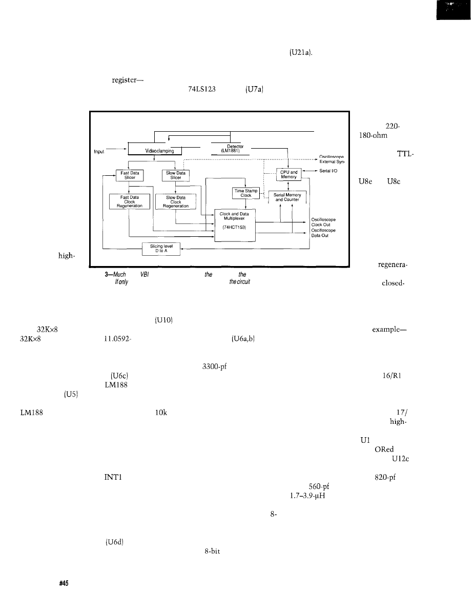
gives the CPU control of the counter,
which it resets and reads the stored
data back at its own pace, converting
the bits into ASCII characters. The
combination of counter and memory
operates as a very large shift
storing the data during the VBI and
spitting it back out again later. This
scheme is neces-
sary because the
8051 cannot keep
up with the data
rate of the closed
caption text or
network clock
data.
during the front porch of each line.
The clamping circuit is driven by the
burst output from the LM1881, but the
burst output is too long and corre-
sponds with the beginning of the clock
run-in, so it must be shortened. This is
done by a
one-shot
which drives the clamping circuit (Ql,
Video
Video Buffer
and
Finally, the
CPU is connected
to both external
data RAM and
program ROM.
The RAM is used
primarily to store
large amounts of
data during
speed teletext
from the DAC0800 (U22) is converted
to voltage by an LM1458 op-amp
R21, R26, and R7 are set to
provide an output voltage range of 0 to
0.5 volts. Since the actual slicing level
is set by the error rate of the data, 5%
resistors are more than adequate.
The outputs from the comparators
are open collec-
tor and are pulled
up with
or
resis-
tors, resulting in
an inverted
level data
Oscilloscope
Video Out
sync
stream. Inverters
and
are
used to uninvert
the bit stream
since both
upright and
inverted data are
needed for clock
regeneration.
A pair of
clock
(WST, NABTS)
Figure
of the
explorer is involved with clocking of various signals found in the vertical blanking
tion circuits, one
operations.
interval.
specific signals
are of interest, only portions of
need to be built.
for the
HARDWARE-THE DETAILS
The core of the VBI Explorer (see
Figure 4) is an 8031 microprocessor
with
EPROM (27256) and
SRAM (43256). An
MHz clock allows for standard baud
rates. Serial I/O is converted to and
from RS-232 levels by a MAX232 (U4).
An LF347 JFET op-amp
acts
as a video buffer, feeding a
1
sync detector
through a low-pass
filter made up of R2 and C8. The
1 provides composite sync,
burst (also known as front porch),
vertical sync, and field outputs. The
field output is especially helpful for
network clock and closed caption data
since these occur only during odd
fields. The vertical sync output is
inverted and presented to
on the
803 I. If software enabled, the 803 1
will generate an interrupt on the
trailing edge of each vertical sync
pulse (the 8031 allows interrupts to be
either edge
or
level triggered-in this
project they are always edge triggered).
Another JFET op-amp
also
acts as a video buffer, providing a
signal which is clamped to ground
R4). After being clamped, the video is
fed to an LM319 dual comparator
for data slicing as well as the
closed-caption peak detector.
Two JFET op-amps
form
the heart of the closed-caption peak
detector. The peak detector is allowed
to charge up a
capacitor (CI3)
whenever a valid line is being received.
During other times, Q2 is turned on,
shorting Cl3 to ground through R12
and resetting the detector. A lo-turn,
trim pot (R13) is used as a voltage
divider and should normally be set
near its midpoint.
Data slicing is done by an LM3 19
dual comparator (UIOa,b)-one
comparator each for the fast (WST,
NABTS, time stamp) and slow (closed
caption) data streams. The slicing
voltage is fed to the noninverting
input, while the clamped video gets
the inverting input. Slicing voltage for
the fast data slicer is supplied by an
bit DAC (U22). The CPU generates
Slice-Data and Slice-Clk, which form
the data and clock inputs, respectively,
for an 74LS 164
serial-to-parallel
shift register (U19). The output current
caption data and
the other for WST and NABTS, create
a clock signal from the teletext data
signal. We’ll use the fast data clock
regeneration circuit as an
the slow clock regeneration circuit
works on the same principle, but
because the frequency is lower, some
component values differ. The capaci-
tor/resistor combination of C
8
acts as a differentiator, generating a
spike upon each low-to-high transition
of the data. The inverted data goes
through a similar combination (C
R19) causing a spike with each
to-low transition. The outputs of both
spikes are inverted by
1 and their
open-collector outputs are
together so the output reaching
(pin 9) consists of a spike each time
the data changes level. An
(C22)
and a
(C18) capacitor across a
variable inductor (L2) form
a tuned circuit whose frequency can be
adjusted to the bit rate of the data (5.72
MHz in this example). The data
transition spikes cause the clock to be
in phase with the incoming data,
resulting in a stream of clock pulses
used for data extraction.
30
Issue
April 1994
The Computer Applications Journal
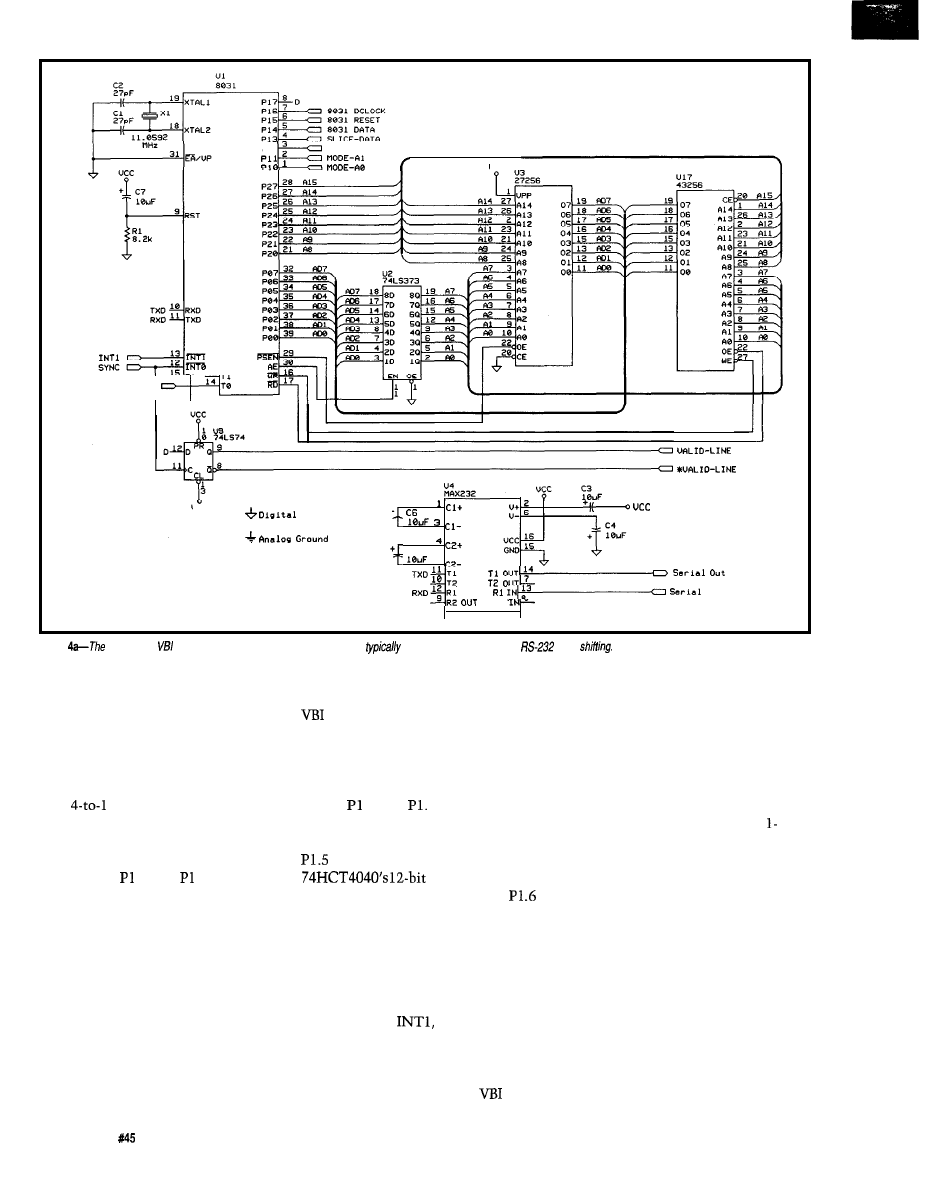
P i 2
F I E L D
u
c
c
S L I C E - C L K
“CC
G r o u n d
+
c 5
5
I N
I N
OUT
I n
R 2
Figure
core of the explorer is the same
8031 controller
circuit
used. A
MAX232
provides
level
Since this system will only be
working with one type of signal at a
time (WST, NABTS, Closed Caption,
or time stamp) there needs to be a way
to take the clock and data information
for each mode and select the one data
and clock signal of interest. U13, a
dual
line multiplexer, does the
trick. The CPU (under software
control) places a number from 0 to 3
on the multiplexer’s address lines via
I/O port pins .O and 1. An address
of “0” selects the closed-caption data
and clock, “1” for WST and NABTS,
“2” for the network time stamp, and
“3” is not used. The outputs from the
multiplexer consist of a single data
signal and its corresponding clock
signal which are used by the data
recovery circuit.
Now let’s review the sequence
that occurs on each interrupt and see
how the hardware and software
interact to capture the data. To start
with, a table is set up in 8031 data
memory consisting of an ordered list of
lines to be read, as well as which
fields (even, odd, or both) that are
needed. Assume all interrupts are
turned off at this point. Suppose we are
interested in closed-captioned data.
Setting .O and
1 to 0 causes only
the closed-captioned data and clock
signals to be passed by U13. Pulsing
briefly from high to low clears the
counter (U15) and
sets the memory address to zero.
will be used to increase the counter
when the computer is reading
memory, so it is set low for now. P1.7
(which I’ll discuss in a moment) is also
set low.
Everything is ready, so interrupts
are enabled on
which will
interrupt the processor at the end of
the vertical sync pulse. The first thing
to do upon the vertical sync interrupt
is to store the address of the
table
as
well as the current VBI line number
minus one in registers. A short
software delay loop is executed to get
past the vertical sync equalizing
pulses. Then the code enables horizon-
tal interrupts to occur via INTO and
exits the vertical sync interrupt
routine.
The basic cycle time of an 1
MHz 8031 is between one and two
microseconds, which is fast but not
fast enough to have the computer read
and store the bits as they come across.
It’s not even fast enough to have the
computer interrupt at each horizontal
sync pulse during the VBI and turn on
the hardware to capture the data. By
the time that would happen, bits
would be lost. Instead, this system gets
things started one line ahead of where
the action is. When a horizontal sync
interrupt occurs, it will increment the
current line number and look at the
first entry in the VBI line table. If it
32
issue
April 1994
The Computer Applications Journal
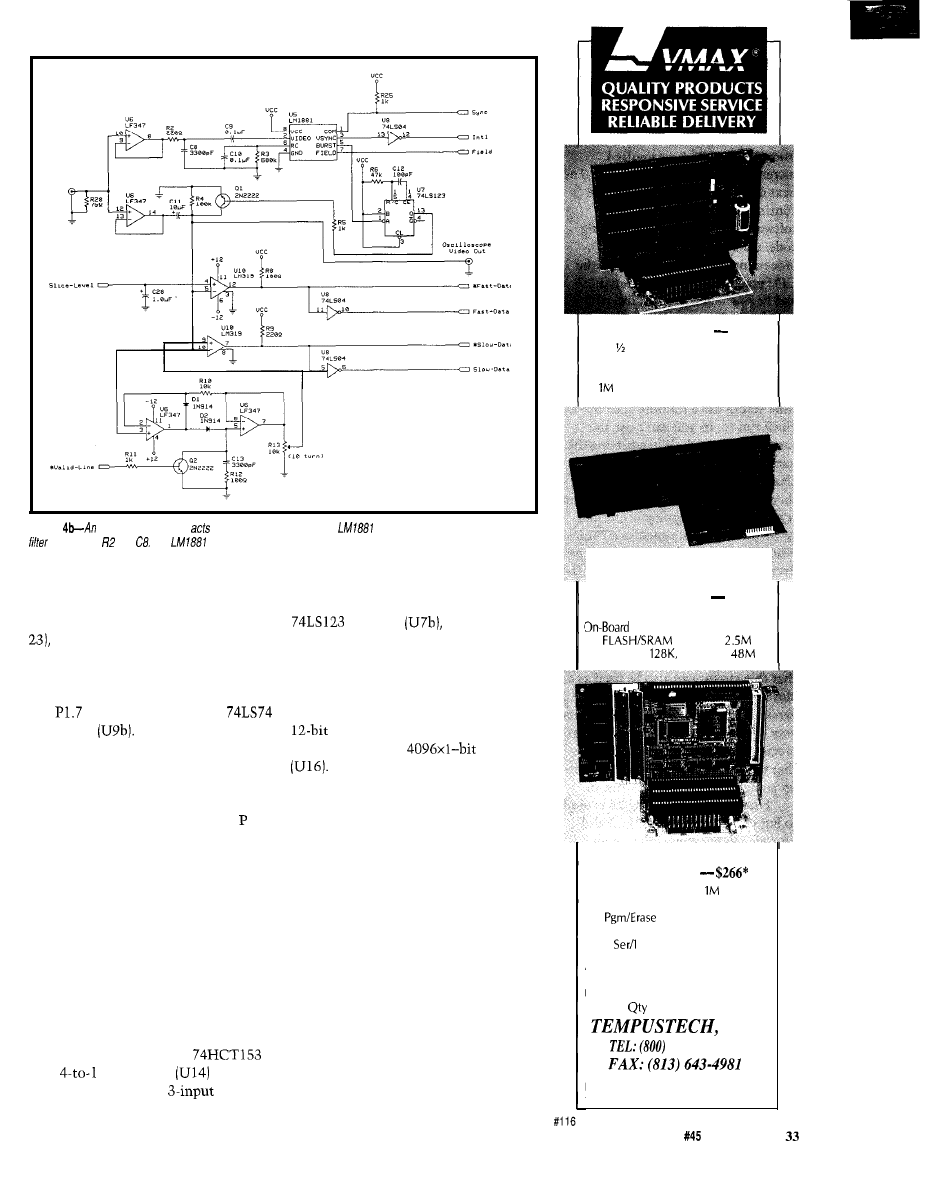
Figure
LF347
JFET op-amp
as a video buffer, feeding an
sync detector through a low-pass
made up of and The
provides composite sync, burst, vertical sync, and field outputs.
matches, P1.7 is set high. The line
table pointer is then incremented to
the next entry. If the system is
receiving the end of the VBI lines [line
horizontal interrupts are turned off
and a flag is set so the rest of the
software can know that this VBI is
done.
table. When Valid-Line is high, the
data clock is allowed to pass through
and generates a signal to fire an
one-shot
creating a
memory-write pulse. When Valid-Line
is low, it lets the output from P1.6 act,
as the clock instead and does not
generate a write pulse.
is the data input of an
D flip-flop
It is set high by the
line that arrives ahead of a teletext
line. The clock input is the composite
sync signal, so the output from the
flip-flop goes high at the beginning of
the next line. It is reset by setting 1.7
low during the next horizontal sync
interrupt, which clocks a 0 at the start
of the next line (unless it is set high by
the software to capture the next line
also). The Q output from this flip-flop
is labeled Valid-Line and is high during
each VBI line we are capturing. It
serves to allow the board to switch
between capturing data and allowing
the CPU to read it back.
The memory circuit consists of a
counter (U15) generating the
address for a 2147
SRAM
If you were building a version of
this circuit for closed captioned or
network time stamp use only, you
could get away with a 1024x1 (or
smaller) memory.
Now all that’s left is to clock the
data into memory and advance the
memory address. Another
dual
multiplexer
is
configured as a folded
truth
When Valid-Line is high and the
system is writing data to memory, the
memory address is advanced one count
for each data clock pulse. If there are
multiple VBI lines to be scanned, data
from new lines is added after the
previous data. There may be a few bits
of garbage generated in between lines,
but the framing codes will let the
system bypass that.
Once the VBI lines have been read
and the horizontal interrupts turned
off, the software detects a flag set
during the last horizontal interrupt.
SOLID STATE DISK $135”
Card 2 Disk Emulator
EPROM, FLASH and/or SRAM
Program/Erase FLASH On-Board
Total, Either Drive Bootable
25MHZ 386DX CPU $695”
Compact AT/Bus or Stand
Alone
SVGA, IDE, FDC, 2 Ser/Bi-Par
Drives to
Cache to
DRAM to
TURBO XT
w/FLASH DISK
To
2 FLASH Drives,
Total
DRAM to 2 M
FLASH On-Board
CMOS Surface Mount, 4.2” x 6.7”
2
Par, Watchdog Timer
All Tempustech VMAX products are
PC Bus Compatible. Made in the
U.S.A., 30 Day Money Back Guarantee
*QTY 1,
breaks start at 5 pieces,
INC.
634-0701
Fax for
295 Airport Road
fast response!
Naples, FL
33942
The Computer Applications Journal
Issue
April 1994
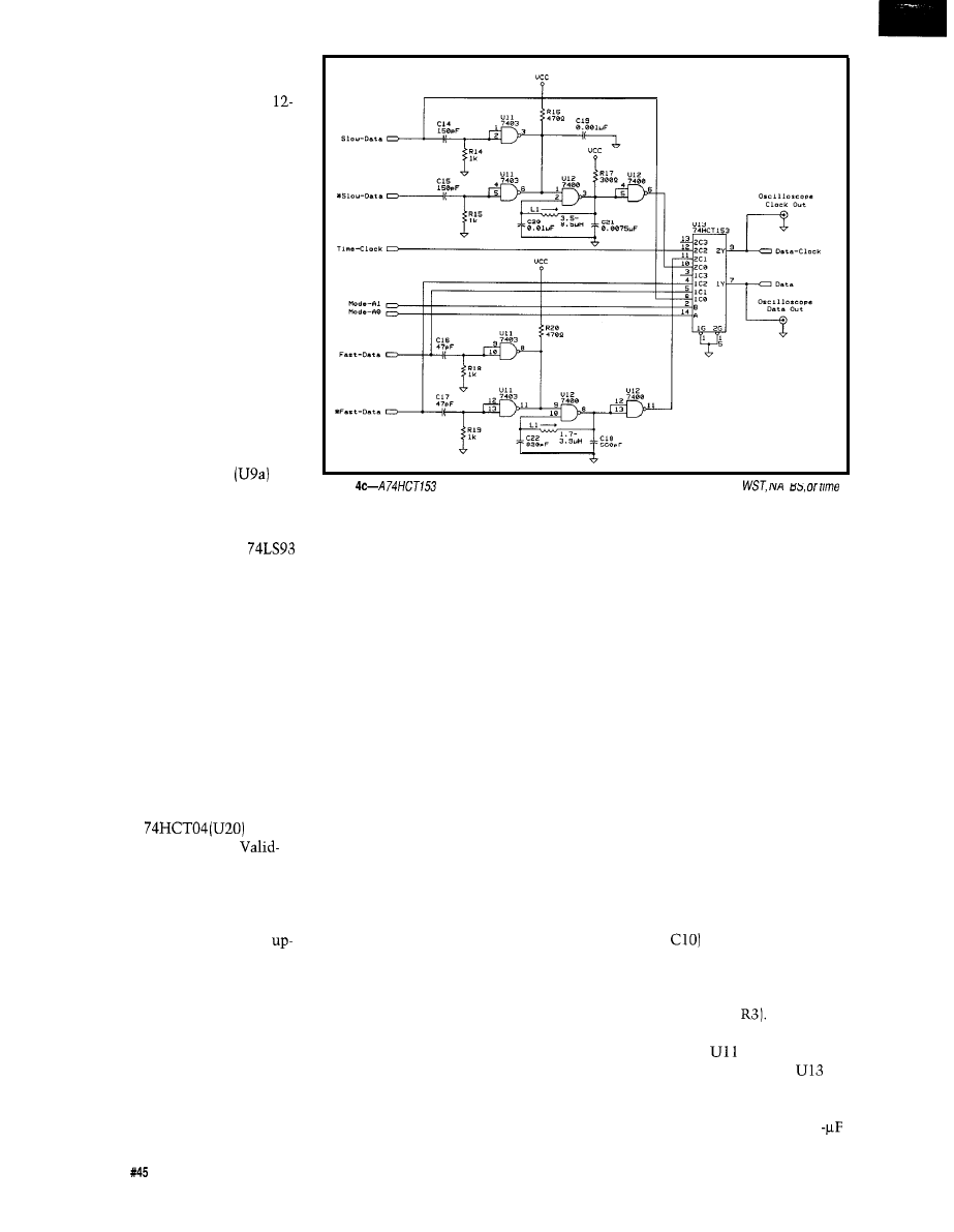
This tells the software, “it’s my turn
now,” and the data crunching begins.
Pl.6 gets pulsed, which resets the
bit counter so the current memory
address is 000. The first data bit is read
from P1.4 and Pl.6 gets pulsed,
incrementing the counter to 001. The
next data bit is read and the cycle
continues. In the meantime, the
software is looking for the framing
code, reading the data bits, and
processing the data. Once done, the
CPU resets the counter, clears P1.7
and P1.6, enables vertical interrupts,
and the cycle restarts.
One last thing. The circuitry to
generate the network time stamp data
is a little different from that used for
teletext. This is because the network
time stamp has a framing code but no
clock run-in, so you can’t use the
tuned circuit trick. When getting the
network clock, a D flip-flop
is
cleared until Valid-Line goes high. It
then waits for the first data bit. When
it goes high, the flip-flop is clocked,
setting Q high. This enables a
4-bit ripple counter to start acting as a
divide-by-four counter, generating the
necessary clock signal. The flip-flop is
reset when Valid-Line goes low. It is
interesting to note that the clock
speeds for the network time stamp and
closed-captioned data are close enough
that this circuit can also be used as a
closed-caption clock-indeed, early
versions of the VBI Explorer used this
very scheme. It requires, however, a
precise slicing level and a guarantee
that the first data on the line be the
up-going pulse of the clock run-in.
Finally, a
is used
to buffer clock, data, and the
Line signals for connection to an
oscilloscope. A NE5090 relay driver
(U24) is used to drive channel chang-
ing relays for automatic control of a
VCR. Hopefully your VCR has an
and-down channel switch instead of a
separate switch for each channel.
You’ll need to modify this section, as
well as a VCR, if you want automatic
channel switching.
SOFTWARE
User interaction with the VBI
Explorer is through a set of about 50
commands, many of which are listed
Figure
multiplexer is
used to select one of four modes: closed captioning,
I
stamp.
in Table 2. On-line help is available for
all commands.
Each type of teletext has its own
group of related commands. Closed
caption and time stamp commands
automatically scan lines 21 and 20,
respectively, of field 1, but this can be
disabled to read caption or clock data
from any VBI line or field. WST and
NABTS require that you manually
specify which lines and fields to use.
Usually this is achieved by combining
the BOTH command with a sequence
of numerical line commands. For
example, to read WST data from the
even and odd fields of lines
14
and 15,
use the BOTH, 14, and 15 commands
in sequence. A number of commands
which set commonly used WST and
NABTS line sequences are provided.
Setting the correct slicing level for
everything other than closed captions
is done through a series of calibration
commands, one each for the WST,
NABTS, and time stamp signals.
Calibration works by scanning through
a range of slicing levels and keeping a
table of errors. A weighted average
then calculates the level with the
lowest error rate. The process is
automatically repeated until the error
rate becomes stable, at which point
that value becomes the new slicing
level. Optimum levels tend to stay
around the same point, especially for
network time stamp signals, therefore
a set of default levels are provided
which can be set in ROM once the
optimum levels for your video source
are known. You can also set the slicing
level manually.
CONSTRUCTION
The current VBI Explorer is built
using wire-wrap techniques on a
ground plane perf board. Because of the
potential noise problems that can
occur when computers and video
signals are in close proximity, I
strongly recommend using a board
with a ground plane. Keep analog and
digital components separated as much
as possible and use a separate analog
ground connected to the primary
ground only at one point. The RC
circuit (R3,
that forms the timing
for the sync detector is particularly
critical, so use good-quality compo-
nents that are heat stable (such as a
metal film resistor for
Best
stability is obtained when non-LS TTL
parts are used for
and U12.
Likewise, use 74HCT parts for
and U14. Keep all component leads as
short as possible. Bypass all chips,
including the analog ones, with 0.1
3 4
Issue
April 1994
The Computer Applications Journal
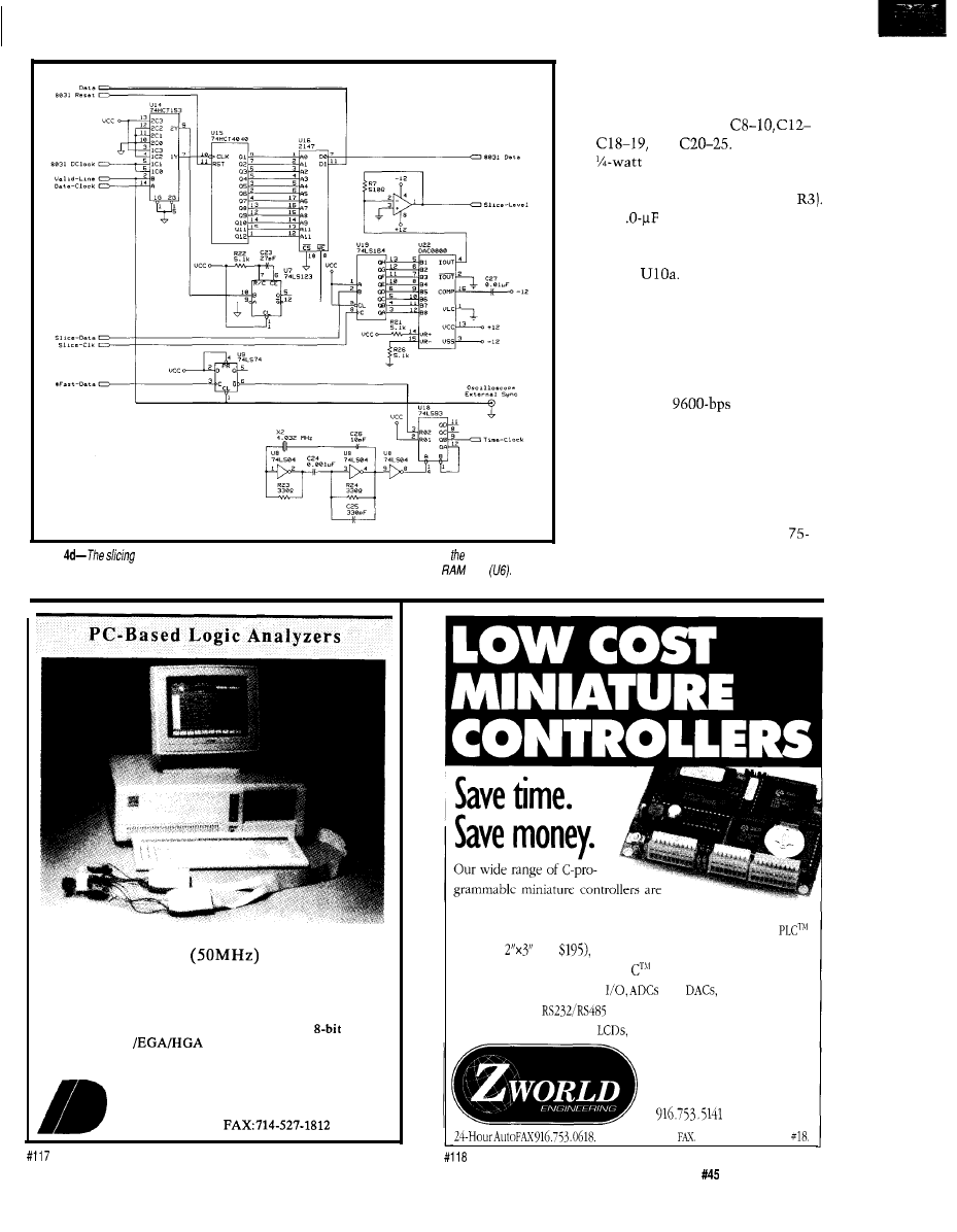
Figure
level can be set dynamical/y by the firmware to minimize errors. Once processor decides
to capture data from a particular line, data is automatically captured and stored in a 4096x1
chip
disc capacitors. Since capacitors are
essential to many of the timing
circuits, use high-quality components,
such as polystyrene, for
13,
and
Except for
R3,
5% carbon resistors are
sufficient (if ventilation is adequate, a
5% carbon resistor can be used for
C28, a 1
electrolytic capacitor,
used to filter digital hash from the
slicing level should be mounted close
to pin 4 of
Use an RF-tight
enclosure to prevent interference with
the video signal.
TUNE-UP
Once you have constructed the
Explorer and done preliminary voltage
tests, connect a
terminal and
apply power. If the memory and
CPTJ
circuits are operational, you should get
a greeting on the screen. Try typing
the
H E L P
command to ensure that
characters can move in both direc-
tions.
Now apply a standard l-volt,
ohm composite video signal to the
video input and view the FIELD,
Sophistication at Low Cost
I D 1 6 0
$ 5 9 5
ID161 (100 MHz) $695
*High Speed
l
8K Trace Buffer
l
16 timing channels
expandable to 32 state channels *Multi-Level Triggering
*State Pass Counting *Event Timer/Counter *Performance
Histograms *Hardcopy Output *Disassembles
micros
*Supports VGA
*Demo diskette available
30 Day Money Back
Guarantee
I N N O T E C D E S I G N , I N C .
6910 Oslo Circle, Suite 207
Buena Park, CA 90621
Tel: 714-522-1469
ideal
for control applications, data acquisition, and test
and measurement. Compact
and low in price (the Little
above is
and
these controllers are programmed
with our easy-to-use Dynamic
development system. Our
controllers feature digital
and
relays and so-
lenoid drivers,
serial ports, battery-backed mem-
ory and time/date clock,
keypads, enclosures and more!
1724
Picasso Ave.
Davis, CA
95616
916757.3737
FAX
Call from
your
Request catalog
The Computer Applications Journal
Issue
April 1994
3 5
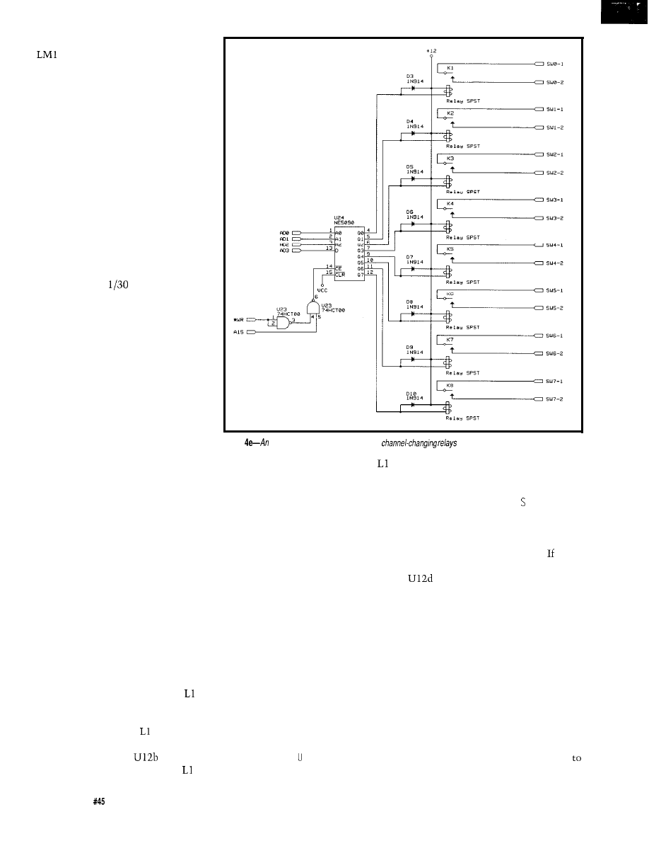
VSYNC, and COM pins on the
88 1 with a scope to ensure proper
sync detection. Now look at the
Oscilloscope Video Out signal. If a
video signal is present, the video
clamp is working properly. For a low
error rate, your video signal must be
virtually noise free. Small amounts of
noise can be tolerated by closed
captions and the network time stamp,
but not with the faster forms of
teletext.
First, get the network time stamp
operational. Feed a video signal from
ABC, CBS, or NBC during prime time
into the Explorer. Type C LOCK and
observe the signal from Oscilloscope
External Sync. If the system is work-
ing, you should see a single pulse
occurring every
of a second.
Connect this line to your scope’s
external sync such that it triggers on
an up-going pulse. Hook the Oscillo-
scope Video Out to the scope and you
should be viewing the network time
stamp-little pulsating blips with a big
blip every second. Type CCAL to obtain
an optimum slicing level. The calibra-
tion command takes anywhere from
10 to 40 seconds to work. Now type
C LOCK again; at this point the CRT
should be displaying the time. Typing
any character exits you from the clock
display back to the monitor. Tune to
other network stations and repeat the
process. Find a slicing value which
works across all three networks,
change the default value in the source
to this value, then reassemble. The
C LOC K command should then work
without having to recalibrate.
To set up for closed-caption
display, tune to any program that has
captions. Type CCC and observe the
video signal. You should see a raw
closed-captioning signal that re-
sembles a rounded version of Figure 1.
Adjust R13 to near its midpoint and
look at the Data Out signal. Adjust it
further so that the clock run-in
resembles a square wave with a 50%
duty cycle (Figure 1). Now adjust
until the CRT output resembles
strings of ASCII interspersed with
command codes. Tune for best
results. If you have a frequency
counter, connect it to
pin 6,
disconnect the video, and adjust to
Figure
NE5090
relay driver is used to drive
for automatic control of a VCR.
a
clock rate near 1.007 MHz. Once
is properly set, it should be left alone.
Tune to other networks and stations
which have closed-captioned signals
and adjust R13 so that the clock run-in
from Data Out best resembles a square
wave for all stations. Type a space to
get out of command mode and type CC.
A decoded version of the closed
captions will appear.
The last features to set up are the
fast teletext signals: WST and NABTS.
Unfortunately, this will be largely
theoretical since both WTBS and CBS
no longer carry teletext magazines as
of 1994. Let’s assume that a WST
signal appears on VBI lines 17 and 18.
Type SETWSTH (a shorthand for setting
capture of lines 17 and 18) followed by
WSTPARITY. Look at
the
Video
Out
signal and assure yourself that VBI
lines 17 and 18 have teletext on them.
Type a space to get back to the
monitor and type W S E 6 8. This tells
the Explorer to use a value of 68 hex
for the slicing level. Type W ST PA R I TY
and observe the clock run-in signal via
Data Out. If it is not a square wave, try
different values for the W U E command
(values can range from 00 to FF). Once
you have a square wave, type W ST
PAR I TY again and tune L2 for the
lowest number of parity errors. you
have a frequency counter, connect it to
pin 11 and adjust for 5.7272
MHz after disconnecting the video.
Once you have minimized the number
of parity errors, type WC A L
to
find the
optimum slicing level. Use W ST
PAR I TY again to fine tune L2 for
minimum errors. The parity error
count should stay on 00 except for an
occasional error. Some scope probes
load the circuit, so if you can’t get 00
errors, remove the probe and try again
using the parity error display to guide
you. Again, once L2 is properly set,
you shouldn’t mess with it. Video
levels will switch slightly from time
time necessitating reuse of the W CA L
36
issue
April 1994
The Computer Applications Journal
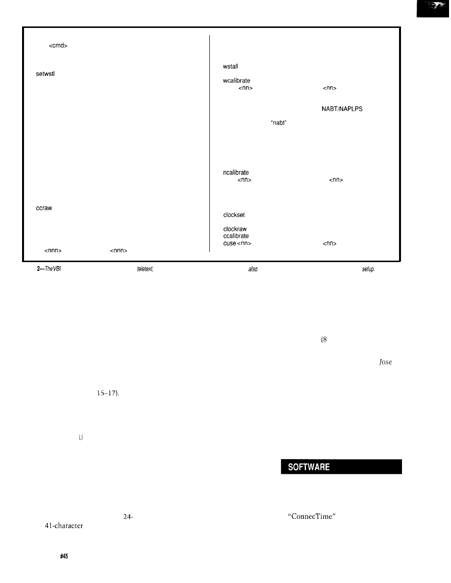
Miscellaneous Commands
help
Prints help for given command
12-22
Set VBI lines to scan
setwst
Shorthand for 15, 16, 17, 18, both
setcbs
Shorthand for 15, 16, 17, both
Shorthand for 15, 16, both
setwsth
Shorthand for 17, 18, both
scope
View VBI lines on oscilloscope
clear
Clear VBI line settings
odd
Interrupt on odd fields only
even
Interrupt on even fields only
both
Interrupt on both odd and even fields
terminal
Use cursor control for displays
show
Display current line, field, and slicing values
default
Use lines 21 and 20 for closed captions and
clock commands (respectively)
nodefault
User-specified VBI lines are used for closed
captions and clock commands
Closed Caption Commands
cc
Decode and display closed captions
cctext
Decode and display text channel
ccclean
Display raw captions with control characters
converted to “(char}”
Output raw captions without any processing
ccnofill
Same as “cc” but no line filling is done
wstbuffer
Display buffer’s worth of data in printable format
wstscan
Read VBI lines and immediately display
wstraw
Send raw WST data directly to serial port
wstclean
WST commands will filter out graphic characters
WST commands will send graphic characters
wstparity
Read VBI lines and display parity errors
Calibrate slicing level for WST
wuse
Set WST slicing level to
(00-FF)
NABTS Commands
nabt
Collect buffer’s worth of
data,
decode into pages, and selectively display
nahex
Like
but display NAPLPS code in hex
nabinary
Like “nahex” but sends raw data for further
processing
nabuffer
Display buffer’s worth of data in printable format
naparity
Read VBI lines and display parity errors
nascan
Read VBI lines and immediately display
naraw
Send raw NABTS data directly to serial port
Calibrate slicing level for NABTS
nuse
Set NABTS slicing level to
(00-FF)
Network Time Stamp Commands
clock
Read time from network and display with
updates
Same as clock, but only displays time once, and
displays program id information if present
World Standard Teletext Commands
Display raw time code in binary
wst
Collect buffer’s worth of data, decode into pages
Calibrate slicing level for network time stamp
and selectively display.
Set clock slicing level to
(00-FF)
pg
Scan for page
and display.
Table
explorer supports
four kinds of
each with ifs own set of commands. There are
several
genera/-purpose commands used during
command. Now type PG 100. Within a
few seconds the index page should
appear. Notice that once the page is
displayed, you are not placed back in
monitor mode. This is so if the page is
updated, or has subpages, they will
automatically be displayed as they
change. Type a space to return to the
monitor.
For NABTS, we will assume three
lines of VBI data are present on lines
15, 16,
and
17.
Type SETCBS (short-
hand for capturing lines
Observe Video Out and confirm three
VBI lines of teletext. If all looks
correct, type NC A L followed by
N A PA R I TY and confirm that the error
rate is low. Type NAB F F E R and wait
several seconds. A printable version of
the raw NATBS code will appear. Type
a space to stop the output and return
to the monitor. Assuming a low error
rate, type NABT and wait for it to print
a page number and ask if you wish it
displayed. Typing Y will print a
reasonable facsimile of the textual
portions of the page mapped to a
line by
screen. As usual, a
space will return you to the monitor.
NETWORK DIFFICULTIES
Problems with reception may not
be due to a problem with the decoder.
More than once have I wasted count-
less hours trying to fix a bug only to
discover the problem originated with
the network. When experiencing
difficulties, always look at the signal
have poor automatic gain control
(AGC), causing large voltage changes
when the picture shifts from mostly
white to mostly black or vice versa.
This causes a higher error rate for
teletext and network clock signals.
Newer VCRs years old or less) tend
to be more reliable.
q
on the scope to make sure it is both
present and reasonable. Attenuation of
The author would like to thank
the clock run-in signal is a common
Sancho and Karen Barnes for their
occurrence with both WST and
help in preparing this article.
NABTS. Diagnosis is obvious by
looking at the scope, but painful
otherwise. Occasionally, the signal
will disappear or selected VBI lines
will be shuffled. Closed captions may
appear on lines other than 2
1.
Remember that captions and other
services are copyrighted and that
copyright laws apply to their use. Also,
services have been known to change
which VBI lines they use from time to
time. There are an increasing number
of proprietary VBI formats found on
cable TV, so don’t be disappointed if
you can’t copy everything.
If you use a VCR for a video
source, be aware that older VCRs may
Mike Barnes holds a B.S. in Computer
Science from the University of North
Texas and an M.D. from the Univer-
sity of Texas Health Science Center at
San Antonio. He is a Family Practitio-
ner with an interest in Medical
Informatics.
Software for this article is avail-
able from the Circuit Cellar BBS
and on Software On Disk for this
issue. Please see the end of
in this issue for
downloading and ordering
information,
38
Issue
April 1994
The Computer Applications Journal

ANSI Standard X3.110-1983: Video/
Teletext Presentation Level Proto-
col Syntax (NAPLPS), December
1983. The official NAPLPS stan-
dard. Essential for decoding
NAPLPS, but Fleming’s series in
Byte is almost as complete.
Benzel, J., and Nuckolls, L.R.,
“Closed Captioning with the
Motorola
The
Computer Applications
May 1993, pp. 12-24. Good intro-
duction to Closed Captioning.
Brand, S., The Media Lab: Inventing
the Future at M.I.T., Penguin
Books, New York, 1988. Excellent
introduction to the idea of personal-
ized information systems.
Chambers J.P., “Enhanced UK
Teletext Moves Towards Still
Pictures,” IEEE Transactions on
Consumer Electronics, Vol CE-26,
August 1980. pp. 527-554. Entire UK
Teletext Specification is listed as an
appendix.
Crowther, G.O., “Adaptation of U.K.
Teletext System for
Opera-
tion,” IEEE Transactions on Consumer
Electronics, Vol CE-26, August 1980.
pp. 587-598. Explains the use of the
“gearing” line.
Electronics Industries Association
(EIA), Joint EIA/CVCC Recommended
Practice for Teletext: North American
Basic Teletext Specification (NABTS).
EIA-516. May, 1988. The official
NABTS standard.
Electronics Industries Association
(EIA), Line 21 Data Services for NTSC.
EIA-608, 1992. The official Closed
Captioning standard.
Fleming, Frezza W., “NAPLPS: A
New Standard for Text and Graphics:
Part 1:” Byte, Feb. 1983, pp. 203-
254. Part 2: Byte, March 1983, pp.
152-185. Part 3: Byte, April 1983,
pp.
Part 4: Byte, May 1983,
pp. 272-284. Excellent detailed
introduction to NAPLPS, almost a
reference in itself.
Holland, G.L., “NAPLPS Standard
Defines Graphics and Text Commu-
nications,” EDN, Jan. 10, 1985, pp.
179-192. Nice overview of
NAPLPS. Has examples of disas-
sembled NAPLPS code.
Mothersole, Peter L., and White,
Norman W., Broadcast Data
Systems: Teletext and RDS.
Butterworths, 1990. Detailed
description of the WST system.
404 Very Useful
405 Moderately Useful
406 Not Useful
calling for a data sheet and price list now.
MICROMINT, INC.
4
Park Street, Vernon, CT 06066
(203) 871-6170
l
Fax (203)
The Computer Applications Journal
Issue
April 1994
3 9

Employer Ownership of
Employee and Consultant
Work Product
known as the
for hire doctrine,” is
that an employer automatically and
without any written employment or
other contract owns copyright in the
works of employees which are pre-
pared within the scope of employ-
ment.’
This rule applies to a wide range
of employee works covered by the
copyright law: writings, art, photogra-
phy, music, computer programs, and
other works. While this would appear
to be a straightforward rule, over the
years a number of different interpreta-
tions of what constitutes an employee
or employment for purposes of this
doctrine arose. In Community for
Creative Nonviolence v.
the
Supreme Court attempted to define
who is an employee for purposes of the
doctrine and to put an end to the
ongoing conflict among the circuit
courts. Despite the Court’s decision in
Reid, it has become clear that many
uncertainties remain.
It is impossible to overestimate
the importance of reducing to writing
the rights of employees, employers,
and independent contractors in
creative work products. Any other
approach leaves at risk the employer
whose employees perform some of
their creative work outside the
traditional workplace, as well as the
employer who commissions free-lance
consultants. The risk is simple. The
person who pays may not own copy-
right in the creative output of the
other person who was paid to create.
Since, in the epic words of an
earlier decision, “no one sells or
Mary M. Luria
Laura Butzel
mortgages all the products of his brain
to his employer by the mere fact of
employment,“” a line must be drawn
between works prepared within the
scope of employment, or
related works, and all other
the latter of which is owned by the
employee. The legal rules for this
drawing are far from clear. The line is
not subject-matter oriented: an
employee can create computer pro-
grams for his employer and computer
programs as a “hobby” or “in his spare
time.” Many, if not most, of the latter
will be owned by the employee. The
line is also not merely “time-of-day”
oriented. The employer will own
works created outside regular working
hours if they clearly fall within the
employee’s duties and regardless of
whether they were produced on or off
the business premises or during or
after work
Conversely, while
the use of the work time, premises,
and assets of an employer points
strongly in the direction that the
resulting work will be owned by the
employer, this too is not totally
dispositive, even for employees in jobs
with expansive. hours and
clock job
This state of the law on works for
hire presents particular problems in
the case of employees who work off
the premises (often at home) in areas
of interest to the employer but not
within the job description or pursuant
to the employer’s instructions. The
number of computer programmers
who work at home on
related hobbies makes this problem
particularly acute in the software
industry, although companies employ-
ing writers and visual artists have been
40
Issue
April 1994
The Computer Applications Journal

experiencing the problem for many
years. Several courts have recently
tried to deal with the problems
affecting software, but with diverse
results which leave the employer with
some uncertainty regarding ownership.
COPYRIGHT OWNERSHIP
In Avtec Systems Inc.
the District Court of the Eastern
District of Virginia held that the
employer did not own the copyright in
such
time” computer software,
since it was prepared outside working
hours and space, not intended for the
employer, and not done to fulfill work
requirements, even though the
software was related to the employer’s
business and the employee allowed the
employer to use prior versions of the
program.’ In Avtec Systems, the
employer was able to prevail on a
separate trade secret misappropriation
claim that the program in question
incorporated its confidential propri-
etary information and that the em-
ployee had breached his fiduciary duty
to the employer, with the result that a
constructive trust was imposed on the
benefits and revenues of the program;
that is, Avtec received a nonexclusive
right to use the program itself and a
share of license revenues, but not the
copyright in the program, or an
injunction against its reproduction,
distribution, or
The message of the Avtec case for
the employer is the employer, absent
trade secret or similar claims, will not
own works of the employee unless:
a. they are of the type the employee
was hired to create;
b. the work is done substantially
within the authorized time and
space limits of the work environ-
ment; and
c. the work is performed, at least in
part, with the purpose to serve the
employer.
On significantly similar facts, the
District Court of South Carolina in
Miller v.
Chemicals
held that
computer programs developed by an
employee, not hired primarily as a
computer programmer, written at his
home, on his own time, without
overtime pay (despite the fact that he
was paid by the hour), and without the
assistance of other employees or the
use of company assets, belonged
employer. The court, looking to the
law of agency, found this work to be
“incidental” to the type of work the
employee was hired to perform as
supervisor of the quality control
laboratory and thus within the scope
of employment. The court also found
that the work was actuated “at least in
part” to serve the employer.” These
factors were held to outweigh the
time-of-day/workplace factors which
the court conceded as “weighing
heavily” in the employee’s favor. The
court summarized as its rationale:
“However, the driving force be-
hind the creation of the computer
programs was to benefit CP by
making the quality control labora-
tory more efficient. Furthermore,
the development of the computer
programs was clearly incidental to
the other work performed by
In other words, the fact that the
programs were created to simplify
Miller’s job and to eliminate errors,
coupled with the fact that the pro-
grams dealt specifically with certain of
the employer’s products, resulted in an
employer-owned work. Nonetheless,
the facts of the case were equally
consistent with the employee’s
argument that he owned the programs
and licensed them to his employer
only for the duration of his employ-
ment. Since the latter license arrange-
ment was only set forth in a letter
from the employee and was not signed
by the employer (although it was
generally known in the company and
posted on terminals], it was ineffective
to rebut the presumption of employer
ownership, which arose once the court
found the work to be created within
the scope of the plaintiff’s employ-
ment.
GET IT IN WRITING
The message of the
Chemicals
case for both employers and employees
is clear: in order to vary the’copyright
law’s presumptions about ownership,
there must be a written contract
signed by both the employer and
employee or, at a minimum, by the
party whose presumptive rights would
be restricted by the
Such
a contract can either broaden or
circumscribe the rights of the em-
ployer-with the opposite result in
regard to the rights of the employee. If
it narrows the rights of the employer,
it must be signed
employer.
The employer may well want to
avoid the uncertainties which result in
cases like the two discussed here, to
say nothing of the expense of litiga-
tion, by means of a written contract
with the employee if there is a sub-
stantial danger that the employee will
create what are arguably out-of-scope
works of interest to the
usually described as works with
significant application within the
employer’s basic businesses. Such a
contract must be clear and specific; it
should not speak vaguely of the
employer’s right to work produced by
the employee at all times or to an
employee’s entire work product. It
may provide that the employer has
only a right of first negotiation or first
refusal of such works and has to pay
money beyond basic salary in order to
secure the copyright or license rights
in such works. The alternative,
however, may be that these works are
never seen until they are in the hands
of third parties. This is an alternative
many employers find unacceptable.
Most employers do not have
written contracts with any of their
employees or have such contracts only
with a limited group of management
and technical employees. Other
employers have employee policies
which are circulated to a wider group
or to all employees. While such
policies could and should address
intellectual property ownership issues,
they may not be adequate as a legal
matter. In this area, the copyright law
requires a bilateral signed contract or
at least a contract signed by the
employee
situation which
restricts the employee’s rights) or by
the employer (in a situation which
restricts the employer’s rights) to vary
the presumptions created by the law
about scope of employment which are
The Computer Applications Journal
Issue April1994
41

discussed in the
Systems and
Chemicals cases. An unsigned policy
statement may constitute some
evidence of what the employer
considered to be the employee’s scope
of employment, but it will not serve to
transfer rights in an out-of-scope work
owned by the employee to the em-
ployer; it might, at most, transfer to
the employer a nonexclusive license,
the only copyright transfer which does
not require an agreement in writing,
but rather only an understanding or
agreement.
In the absence of an agreement,
the uncertainties in determining
whether a work is owned by an
employer or employee can be great.
Even more uncertainties arise when it
is not clear whether a hired individual
is an employee or an independent
consultant. Recent case law strongly
suggests that the employer may pay
for, but will not own, copyright in
works of individuals who work for pay
on or off the employer’s premises but
do not receive benefits, unless there is
a written contract signed by both in
which work-for-hire status or em-
ployer ownership is expressly agreed.
INDEPENDENT CONTRACTORS
In Aymes v.
the 2d U.S.
Circuit Court of Appeals held that the
most important features of the hiring
relationship which distinguish an
employee from an independent
contractor are the putative employer’s
treatment of the employee for benefits
and tax purposes. In this case, Aymes
was hired to work as a computer
programmer to create a series of
programs over a period of two years.
He never received health or insurance
benefits. His employer never paid the
employer’s percentage of payroll taxes,
nor did the employer withhold federal
or state taxes on the employee’s
income, paying Aymes instead on a
gross basis and providing a Form 1099,
rather than a W-2 Form. This proved
fatal to the employer’s later claim of
ownership of copyright in the pro-
grams written by Aymes. According to
the 2d Circuit:
“The failure of Island to extend
Aymes any employment benefits
or to pay any of his payroll taxes is
highly indicative that Aymes was
considered an outside independent
contractor by Island. Indeed, these
two factors constitute virtual ad-
missions of Aymes’s status by
Bonelli himself. Moreover, they
also point out a basic inequity in
Aymes’s treatment. Island ben-
efited from treating Aymes like an
independent contractor when it
came to providing benefits and
paying a percentage of his payroll
taxes. Island should not in one
context be able to claim that Aymes
was an independent contractor and
ten years later deny him that sta-
tus to avoid a copyright infringe-
ment
Aymes had sued for copyright
infringement after he left this job,
based on his former employer’s alleged
breach of an oral agreement limiting
the use of the computer programs in
question to a single computer at a
single site. The employer defended by
claiming that, as a result of the
employment relationship, it owned the
copyright on the programs it was
alleged to be infringing. The 2d Circuit
considered as relevant a few other
indicia of whether Aymes was an
employee (employer’s right to control
manner and means of work, level of
skill of work required, employer’s right
to assign additional
but found
the benefits/tax point dispositive.
The Aymes case was remanded to
the trial court to consider whether the
employer contributed enough to the
creation of the programs so that it was
a joint copyright owner and, therefore,
not an infringer.”
The message of the case for 2d
Circuit (New York, Connecticut, and
Vermont) employers is clear: if a hired
individual is not an employee for
benefits/tax purposes, he or she is
unlikely to be treated as an employee
for copyright purposes and, therefore, a
written work-for-hire contract signed
by both parties is necessary if the
employer is to own the copyright on
the “employee’s” creative output. (The
employer could also seek to receive in
writing an assignment of the copyright
or an exclusive license signed by the
employee.) According to the 2d
Circuit:
“The importance of these two fac-
tors is underscored by the fact that
every case since Reid that has ap-
plied the test has found the hired
party to be an independent con-
tractor where the
hiring party
failed
to extend benefits or pay social
security
California takes the same position
as a matter of statutory law, so several
of the most commercially significant
states are in agreement on this point.
There are a number of post-1989
cases in other geographic areas which
have the same effect, but articulate the
rationale less clearly.” Many of these
cases focus strongly on the issue of
employer control and “employee”
independence, rather than benefits/tax
issues, and it now seems clear that
these three issues will emerge as the
most significant from the Reid
case’s
longer list in distinguishing employees
from independent
It should be added that in Playboy
Enterprises Inc. v.
the
District Court in the Southern District
of New York stated that “work made
for hire agreements must precede the
creation of the work.” The court found
that works prepared by an independent
contractor and artist were not specially
ordered or commissioned and thus not
works made for hire. However, the
court stated that assuming the works
were specially ordered or commis-
sioned, the writings establishing the
works as works made for hire did not
precede the works
As a
result the artist owned the copyright
in his work product.
FINALLY...
All too many employers use no
contractual paperwork in arrange-
ments with consultants, so that the
only “documents” relating to the
employment relationship or copyright
ownership in the commissioned works
are the checks and the Form 1099
issued to the consultant. Under these
circumstances, the “employer” will be
working with an independent consult-
ant and the latter will own the
42
Issue
April 1994
The Computer Applications Journal
copyright, leaving the former with (at
most) a nonexclusive license no matter
how much development money has
been paid. This will continue to be an
important issue as long as the Copy-
right Act incorporates the work for
hire doctrine.
There is some prospect that the
portion of the doctrine which deals
with independent contractors may be
amended after decades of debate, but it
seems less likely that the treatment of
true employees will be changed. Even
if the Copyright Act is amended, there
will be an important group of
works which continue to be
subject to the doctrine for the full term
of copyright.
q
Mary M. Luria is a partner of
Patterson, Belknap, Webb Tyler’s
Intellectual Property Group. Laura
Butzel is associated with the firm.
407 Very Useful
408 Moderately Useful
409 Not Useful
Copyright Act of 1976, 17 U.S.C.A.
(West
1993).
490 U.S. 730 (1989).
Public Affairs Assocs. Inc. v.
Rickover, 177
F. Supp. 601, 604
(D.D.C.
Rev’d on other
grounds, 284
262 (D.C. Cir.
Vacated for insufficient
record, 369 U.S. 111 (1962).
Marshall v. Miles Laboratories 647
F. Supp. 1326 (N.D. Ind.
nical article written at home at
employee’s initiative held to be
owned by employer).
Bros. Inc. v. W. Goebel
Porzellanfabrik KG, 589
F. Supp.
497
1984) (drawings used
to produce porcelain figurines
created by nun held to be owned by
her despite convent support of all
her activities];
Public Affairs
Associates Inc. v. Rickover, 284
F.
Supp. 444 (D.D.C.
of
Vice Admiral written and delivered
on his own time but duplicated on
government equipment held to be
owned by him).
6. 805
F. Supp. 1312
Va. 1992).
7.
Id.
at 1318-19.
8.
Id.
at 1319-22.
9.808 F. Supp. 1238 (D.S.C. 1992).
Restatement (Second) of Agency
229 comment b (1958)
11.
Id.
at 1243.
12.
Id.
at 1244.
13. Copyright Act of 1976, 17 U.S.C.A.
(West Supp. 1993).
14. 980
857 (2d Cir. 1992).
15.
Id.
at
862.
16.
Id.
at
862-63.
17.
Id.
at
864.
18.
Id.
at
863.
19. See e.g.,
Marco v. Accent Publishing
Co. Inc., 969
1547 (3d Cir. 1992).
20. See e.g.,
Respect Inc. v. Committee
on the Status of Women,
815 F. Supp.
1112
1993).
21. 831 F. Supp. 295 (S.D.N.Y. 1993).
22. See also
Schmidt Inc. v.
Corp., 769
410 (7th
Cir. 1992).
EXPRESS CIRCUITS
MANUFACTURERS OF PROTOTYPE PRINTED CIRCUITS FROM YOUR CAD DESIGNS
TURN AROUND TIMES AVAILABLE FROM 24 HRS
2 WEEKS
Special Support For:
l
TANGO. PCB
l
TANGO SERIES II
l
TANGO PLUS
l
PROTEL AUTOTRAX
l
PROTEL EASYTRAX
l
l
l
II
l
EE DESIGNER I
l
EE DESIGNER III
l
ALL GERBER FORMATS
l
FULL TIME MODEM
l
GERBER PHOTO PLOTTING
WE CAN NOW WORK FROM
YOUR EXISTING ARTWORK BY
SCANNING. CALL FOR
DETAILS!
Circuits
Quotes:
1150 Foster Street
l
Box 58
l-800-426-5396
Industrial Park Road
Phone: (910) 667-2100
Wilkesboro, NC 28697
Fax: (910) 667-0487
The Computer Applications Journal
Issue
April 1994
43
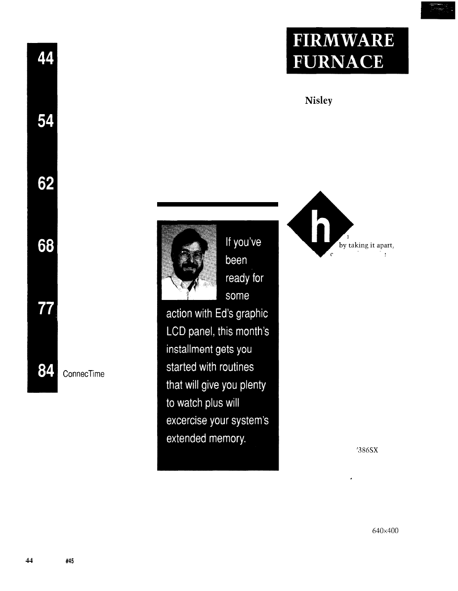
DEPARTMENTS
Firmware Furnace
From the Bench
Silicon Update
Embedded Techniques
Patent Talk
Ed
Bringing the ‘386SX Project’s
Graphic LCD Panel to Life
ave you ever
repaired something
contemplating the
pieces, then putting them back
together again? It’s hard to believe a
simple laying on of hands can fix an
inanimate object, but quite often that’s
what happens.
Textbooks relate such problems to
contact corrosion, random glitches,
metastability, software errors, and
similar maladies. Experienced engi-
neers and technicians know differ-
ently. “That widget just needed some
attention,” they’ll say with a smile
and go on to the next problem. To hear
them talk, you’d almost think it was
alive.
In the previous two columns, I
covered the Graphic LCD Interface’s
hardware and some test routines to
exercise the circuitry. This month I’ll
describe routines that manipulate
individual dots on the panel and, as an
added bonus, put your
system’s
extended memory to good use.
While the code isn’t alive yet,
we’re getting there..
PUTTING LIFE TO WORK
Graphic LCD panels have a
voracious appetite for data: testing the
drawing routines means exercising a
quarter-million dots in that
array. Just writing and reading a byte
Issue
April 1994
The Computer Applications Journal
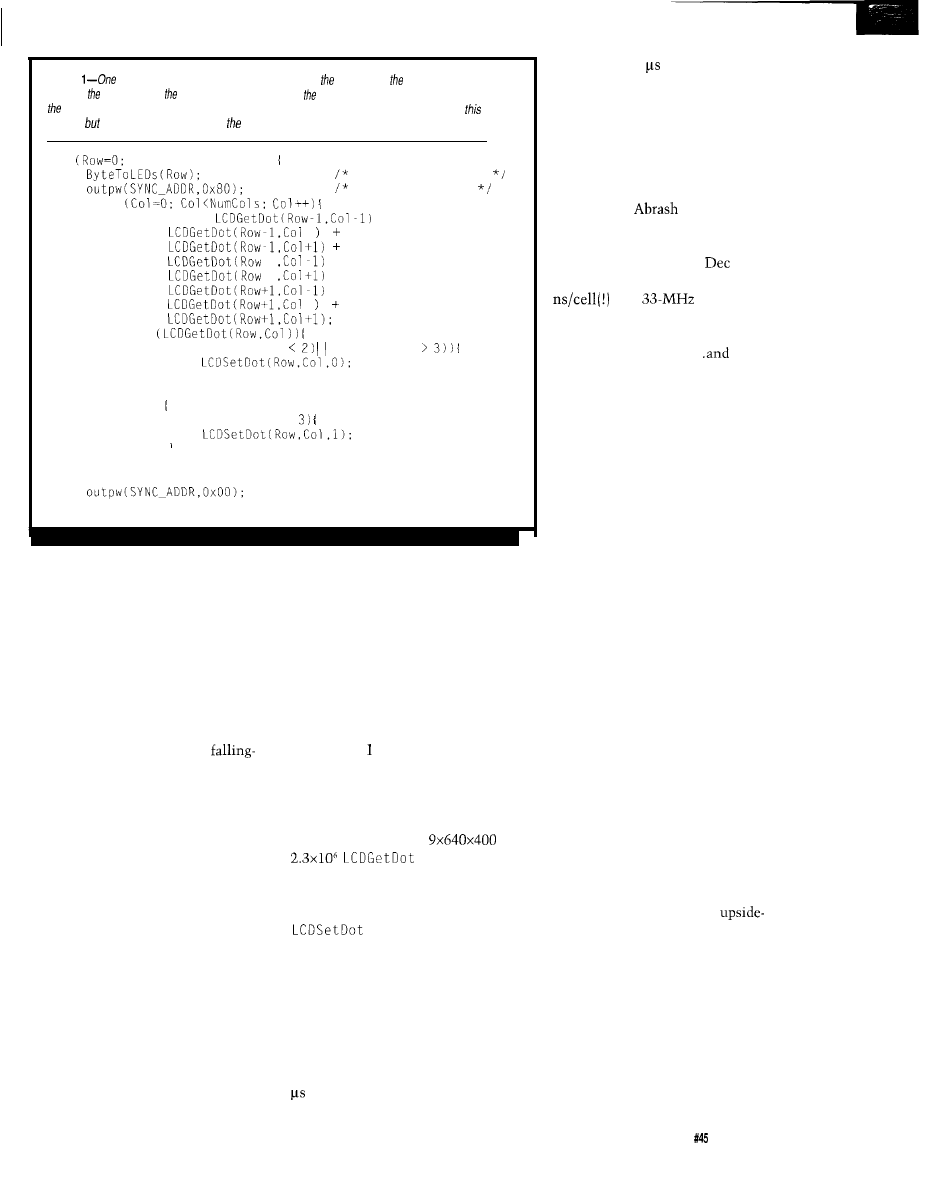
Listing
of the
attractions of Conway’s Game of Life is simplicity of algorithm: these few lines
defermine changed cells in next
generation. Because graphic LCD panels are so
large, however,
complete computation can fake fens of seconds even on a fast processor. For our purposes
is fast
enough, you can have fun optimizing code beyond recognition.
for
Row<NumRows; Row++)
show some progress
for scope timing
for
Neighbors =
+
+
+
+
if
if ((Neighbors
(Neighbors
else
if (Neighbors ==
correctly doesn’t mean that the dots
A dead cell remains dead unless
appear at the right place on the panel,
so you must actually look at the
results to see if it’s working. But who
wants to watch a test pattern!
Conway’s venerable Game of Life
is the great-to-the-nth grandfather of
today’s Artificial Life creations. It
produces an easily recognizable set of
patterns, exercises the whole LCD
panel, is fun to watch, and is
off-a-log easy to code.. .if performance
isn’t an issue, anyway.
The playing field is a rectangular
grid of cells, each of which may be
either “alive” or “dead.” The field
should be infinite, but typical imple-
mentations surround the visible part of
the field with permanently dead cells
or join the four borders to simulate a
torus. The initial cell contents
uniquely determine the course of the
game, so Life isn’t interactive.
Play proceeds by generations and
the state of all the cells changes at one
instant at the end of each generation.
The state of each cell in the next
generation depends on its current state
and the state of its eight immediate
neighbors.
exactly three of its neighbors are alive,
in which case it springs to life in the
next generation. A live cell remains
alive if exactly two or three of its
neighbors are alive, otherwise it dies of
either loneliness or overcrowding.
Variations on those rules are possible,
but tend to produce less interesting
patterns.
Listing shows the few lines of
code needed for this algorithm in its
most basic form. A little arithmetic
shows how much computation is
needed for a field filling a 640x400
LCD panel. There are
=
calls per genera-
tion!
Relatively few cells change state
after the first few generations, so the
calls don’t influence the
overall time. I used two separate fields,
one in system RAM and the other in
the LCD Refresh buffer, but the few
milliseconds devoted to copying the
“new” dots into the “old” buffer at the
end of each generation have no effect,
either.
The calculations take about 100
per cell, so computing one genera-
tion takes 100 x 640 x 400 = 26
seconds. Watching this is similar to
studying the life cycle of glaciers in
real-time. Smaller panels are faster,
but remain in the icicle-growth
competition. This is obviously a
program where optimization pays off
handsomely!
Michael
presented a Game
of Life Optimization Challenge in the
June ‘92 PC Techniques, with the
results appearing in the
‘93 issue.
The two winning entries run at 125
on a
‘486 and their
source is a wonder to behold. Before
you start tweaking my simple code,
read those two articles..
weep.
Because I was more interested in
LCD panels than the Game of Life, I
decided to cheat. I added a smidge of
code to store each generation in
extended memory, then play them
back as a sort of slide show. You’ll get
the details after we cover the LCD
routines.
DOING DOTS
The Graphic LCD Interface maps
the LCD’s dots into a 32K chunk of
the PC’s address space. From the
CPU’s viewpoint, the LCD panel is
just a relatively slow RAM with the
useful side effect that the bits are
visible to the naked eye. Unfortu-
nately, each panel has its own dot
layout, so we need unique code to find
each dot in RAM.
Finding a dot requires two steps:
selecting the RAM byte holding the
bit, then isolating the bit within that
byte. Obviously, both steps depend on
the dot’s row and column address. To
simplify the high-level code, rows and
columns start at 0 in the upper-left
corner of the panel even though the
LCD panel documents number them
differently. Other mappings are
certainly possible, so if an
down or backwards mapping suits your
needs, go for it!
As you saw last month, the top
row of dots on the LCD panel does not
come from the first group of bytes in
RAM. The Graphic LCD Interface
produces a Frame Sync pulse when it
resets the address counters to zero, but
the panel expects Frame Sync to follow
the first row. As a result, the dots
The Computer Applications Journal
Issue April 1994
4 5
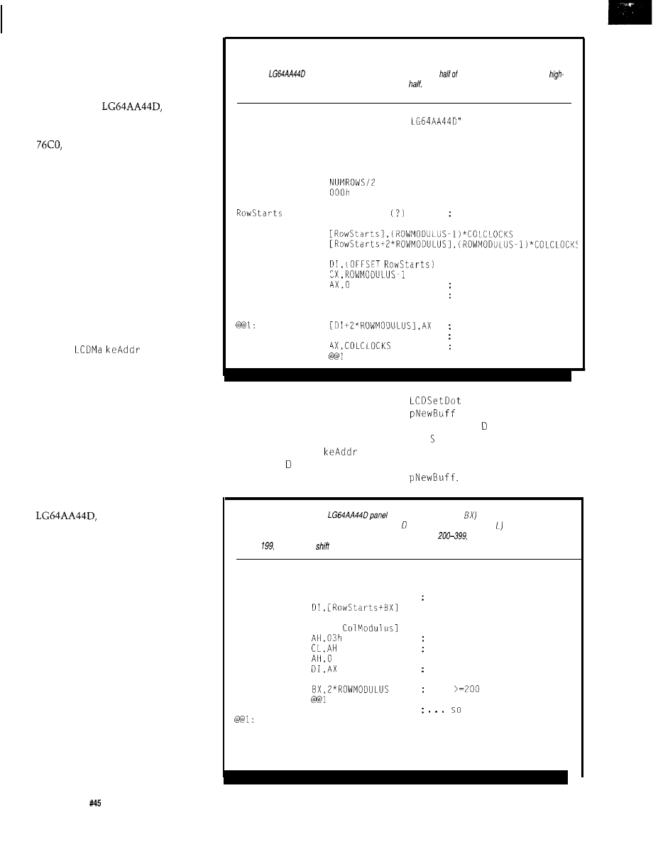
starting at address 0000 appear on the
second panel row.
The quick and easy solution for
this appears in Listing 2. The starting
address of each row is stored in a table,
which, for the
has 400
entries. The first entry points to the
bytes starting at address 199 x 160 =
while the second entry holds
address 0000. The dot drawing rou-
tines use the table to find out where
the rows start, so the scrambled
addresses unscramble the panel layout
to put Row 0 at the top of the panel
where it belongs.
I fill the table as part of the LCD
initialization function. Entries 0 and
200 are special-cased at the top of the
loop, while the remaining 2 through
199 entries are a simple ascending
sequence. I suspect you could define
and fill the table using some assembler
macro magic, but this way is easy
enough.
The
function in
Listing 3 converts a dot’s row and
column address into a byte address and
a bit shift amount. The byte address
depends on both the row, which
specifies the lookup table entry, and
the column, which specifies an
additional number of bytes from the
start of the row.
These LCD panels pack several
dots in each byte, so I use the bit shift
value to move the selected bit to the
low-order bit or vice versa. For the
the shift amount
depends only on the column, but the
LM2 15, which I’ll describe later, is
more complex.
Homework assignment: step
through the code with a pencil and
paper to see how the algorithm works.
Draw a picture of the LCD panel’s bit
layout, indicate the bit addresses at the
start of each row, then verify that the
code really does produce the right
answers. You won’t believe it until
you do....
Listing 4 pulls all of this together
to write a single dot. As you saw in
Listing 1, LCDSetDot
is
called directly
from the main C routine, so its register
and stack usage must match C’s
expectations. This used to be fiend-
ishly tricky, but current assemblers
include several high-level directives to
Listing 2-A lookup table
simplifies finding the RAM address of a particular dot by ho/ding the starting
address of the corresponding row. This code excerpt defines and loads the 400 tab/e entries needed for a
Matsushita
640x400-dot panel. The data for the lower
the pane/ is located in the
order nybble of the same bytes displayed on the upper
so the second half of the fable (rows 200-399)
contains the same addresses as the first half (rows o-199).
LCDNAME
EQU
"Matsushita EDM
NUMROWS =
400
NUMCOLS =
640
COLCLOCKS =
160
COLMODULUS =
4
TOTALCLOCKS =
32000
ROWMODULUS =
FILLVALUE =
D W
MOV
MOV
NUMROWS DUP
row starting addresses
MOV
MOV
MOV
PUSH
POP
+ 2
row 0 = second entry
DS
set up STOSW segment
ES
MOV
STOSW
ADD
second half of table
first half
offset of next row
LOOP
ease the task. I won’t go into the
adds the far pointer in
details here, but it’s a lot easier than
to
DI tocreatethefinal
counting bytes and tweaking registers
address in ES
: I. You
can aim
on your own.
LCD e t D
O
t at the actual LCD refresh
Recall that LCDMa
returns
buffer RAM or a separate working
a byte offset in I rather than a
buffer in system RAM just by changing
complete segment:offset address.
Listing
3-This routine for an
converts a dot’s row (in
and column [in
AX) address
into the offset of a byte from the start of the buffer (in I) and the shift amount (in C needed to align the
bit in Bit 0. The high nybble of each byte stores the dots for rows
the low nybble has rows 0
through
and thus the
amount depends on which half of the pane/ holds the dot.
PROC
LCDMakeAddr
ADD
BX,BX
make word table index
MOV
DIV
[BYTE
XOR
flip shift direction
MOV
save remainder for shifting
MOV
ADD
DI points to the byte
CMP
rows
use high nybble
JB
ADD
CL,4
shift into it
RET
ENDP
LCDMakeAddr
4 6
Issue
April 1994
The Computer Applications Journal
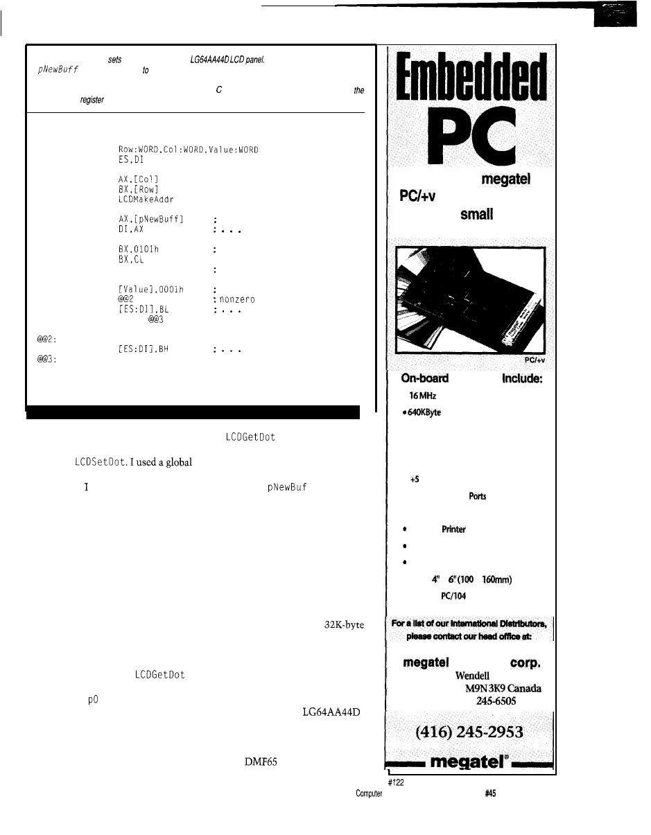
Listing
4-This routine
or clears a dot on the
The global variable
contains a farpointer the target buffer, which may be the LCD panel or a chunk
of
system
RAM. Depending on your application you may want to include the target address as one of the function
parameters. This code can be called directly from the main program because the first four lines hand/e
inferlanguage
and stack conversions.
PUBLIC
C LCDSetDot
PROC
LCDSetDot
ARG
USES
MOV
MOV
CALL
LES
get buffer base pointer
ADD
update byte pointer
MOV
set up
bit mask
SHL
NOT
BL
BL = AND mask. BH = OR mask
TEST
what do we want?
JNZ
means set the bit
AND
clear it
JMP
SHORT
OR
set it
RET
ENDP
LCDSetDot
Normally you would include the
buffer base address in the arguments
youfeedto
variable to reduce the amount of stack
shuffling, but agree that globals can
cause problems in a real application.
As always, use this code as the basis
for your own rather than The Final
Word on style.
and
LCDSetDot use
two different global pointers because
the Game of Life’s field must remain
unchanged until all the old cells are
tested. I aimed
f
at the LCD
refresh buffer so you could watch the
dots appear, but you could put them in
system RAM. Just copy them all to the
LCD RAM at the end of each genera-
tion to reveal the new field.
BX
holds the bit masks needed to
set or clear the selected bit. Although
only one instruction touches the target
byte, the CPU actually makes two
memory accesses: one to read the
current dots and another to write the
updated byte. This is as fast as you can
do it, but the LCD RAM on the ISA
bus is achingly slow compared to
DRAM on the system board.
Listing 5 shows how
tests an LCD bit. In this routine the
global far pointer
1 d Buff sets
the
buffer’s RAM address. The shift
amount in C
L
now moves the selected
bit into the LSB of
AX,
where it’s
masked off to make a boolean value for
the calling routine.
The main loop calls
LCDSetDot
only when a cell changes, which
means that new field must contain the
old cells at the start of each genera-
tion. I used the C
memcpy
library
function to copy the entire
buffer at the end of each generation.
Compared to the time needed to
compute a generation,
memcpy
is
essentially free.
VARIATIONS ON A THEME
Even through the
panel has a relatively complex dot
layout, the code is still fairly simple.
Rather than list the routines for the
640x200
1
and the TLY-365
“The new
offers on-board
VGA in a
rugged
form factor.”
Features
l
V-40 CPU
User DRAM
l
On-Board VGA
Video/LCD
display controller
l
Power Consumption under 2 watts,
volt only operation
l
3 RS-232 Serial
. Floppy, SCSI, Keyboard Ports
Parallel,
Port
PC Compatible BIOS
Real Time Clock
l
Only x
x
l
ISA and
Bus Options
computer
125
Ave.
Weston, Ont.
Fax: (416)
The
Applications
Journal
Issue April 1994
4 7
Data Acquisition
and Control
Without Compromise
Programmable Scan Burst
Advanced Industrial Control
boards set a new performance
standard for general purpose
industrial laboratory applications.
ADA2210 with
A cost-effective solution
features:
I
125
XT throughput
SE. 8
12-bit analog inputs
I
selectable input range
I programmable auto channel scan
I programmable burst mode
I software external triggers, pacer clock
I on-demand DMA transfer
I programmable gain:
I3 cascadable
counters
I 16 programmable digital I/O lines
I two
analog outputs, selectable range
I
Universal TSR DOS driver
I
Notebook driver
HARDWARE SOLUTIONS
AIC family also includes AT
analog
I/O
boards,
only A/D control boards for
PCs, 4-20
current loopoutputs,
opto-22 compatibility.
SOFTWARE SOLUTIONS
the power and performance of
or
from
library of application programs for
data acquisition and analysis, control,
and 3D graphics.
For more information on these and other
ISA
bus and
products,
call, write
us today!
Place your order now and receive
and
for
Real Time Devices, Inc.
P.O.
Box
906
State
College, PA 16804
(814) 234-8087
n
Fax: (814) 234-5218
121 panels, I’ll aim you at the BBS for
the source code if you need it.
I
decided not to do the 640x400 Sharp
panel because the inverters are so hard
to find, but if you have one I’ll be glad
to kibitz.
The 480x128 LM215 merits some
discussion because it is so peculiar.
Again, check the BBS for the actual
code. Each of the four bits in the low
nybble drives a separate quadrant: the
panel has four 240x64 subpanels. It
uses a
Dot Clock, so the dots
must be duplicated in successive
and odd-addressed bytes in the LCD
refresh buffer to present stable data to
the panel.
The
row address table
has 128 entries, corresponding to the
128 visible rows. The code I used to fill
it resembles that shown in Listing 2.
I
put only the even addresses in the
table and modified the
and
LCDSetDot functions to generate the
corresponding odd addresses as needed.
In the
function, the
bit shift amount depends on the dot’s
quadrant, so I used the ‘386 S ETA E
instruction to generate a boolean value
from the CM P instructions rather than
interject several branches. The byte
offset added to the table entry is the
same for the first and last 240 columns
in each row. S ETA E doesn’t exist on
8088 or 80286
which means
you must tweak the code if you’re not
using a ‘386.
The LM215 LCDSetDot function
updates both bytes with the new dot
value. Apart from that, it’s basically
the same as the code for the other
panels because LCDMa
handles
the peculiar bit and byte addressing.
The LCD initialization routines
for all these panels disable blinking by
gating a constant zero to the LCD Data
M
UX
(U54). While there are good
reasons for blinking dots, the Game of
Life doesn’t need any, so it’s left as an
exercise for the interested reader.
STASHING SLIDES
I used the Game of Life to produce
dots because it is far more interesting
than a bland test pattern, but waiting
half a minute for each update is a
strain on even the most placid atten-
tion span. Rather than get involved
with code optimization, I decided to
store successive generations in RAM
and then play them back quickly.
While the slide show repeats after a
while, that’s OK in this application
because you can study problems as
they crop up over and over again.
So far in this series our ‘386SX
have been running in Real
mode, so only 20 address bits are
active and storage is limited to 1
megabyte. The PC’s memory address-
ing restrictions [discussed in Issues 36
and 37) limit contiguous RAM to 640K
starting at address 00000. After loading
a program, allocating a few work
buffers, and leaving room for a decent
far heap area, there’s only a few
hundred kilobytes left over.
In contrast, when a ‘386 CPU runs
in Protected mode, it uses 32 address
bits to reach 4 GB of memory. The
has only 24 address pins and is
thus limited to only 16 MB, but that’s
significantly more than 640 KB. In PC
systems, the first megabyte of the
Protected mode address space is
devoted to the familiar Real mode
RAM and I/O devices, with the
remaining storage appearing as a
contiguous expanse starting at the
MB line.
This RAM is called “extended”
memory to distinguish it from “ex-
panded” memory that is page-mapped
into the lower 1 MB. The (now largely
irrelevant) LIM 4.0
defines the
operation of a standard DOS Expanded
Memory Manager that controlled
actual hardware. The EMM386 DOS
device driver controls extended
memory and can simulate expanded
memory with no additional hardware.
Your ‘386SX system board
probably has a multiple of 2 MB of
RAM because the CPU addresses
memory in two-byte chunks. Typical
(cheap)
are one byte wide [plus
a parity bit) so they must be installed
in pairs. You need at least 1 MB to run
the system, and two 1
are cheaper than four
parts.
QED. In any event, you have more
memory available beyond 1 MB than
you do below it!
Although the CPU must run in
Protected mode to access expanded
memory, we don’t need a complete
Issue
April 1994
The Computer Applications Journal

Listing
routine tests a dot on
LCD panel and returns ifs state as a Boolean
value. the row or column lies outside the LCD’s boundaries return value is always zero. While this
simplifies the higher-level code for the Game of Life, if may
be the right action for programs!
PUBLIC
C LCDGetDot
PROC
LCDGetDot
ARG
USES
XOR
set up zero return value
MOV
verify column
TEST
negative?
JNZ
@ D o n e
CMP
too big?
JAE
y e s
MOV
verify row
TEST
negative?
JNZ
@ D o n e
. . . yes
CMP
too big?
JAE
@ D o n e
. . . yes
MOV
set up column number
CALL
LES
get buffer base pointer
ADD
update byte pointer
MOV
fetch the byte
SHR
AL,CL
skid our bit into LSB
AND
isolate it
@@Done:
RET
ENDP
LCDGetDot
Protected mode program. The system
BIOS includes functions to copy blocks
of data to and from the 1 MB available
to Real mode programs, so we can
create the data as usual and dispose of
it through a BIOS call.
The first step is finding out how
much extended memory is available
on the system. Listing 6 shows the
code needed to access BIOS Int 15 (hex,
remember) Function 88 (likewise),
which returns the extended memory
size in kilobytes in register AX.
Because AX is only bits wide, the
maximum memory this function can
handle is merely 64 MB..
for
the
but painfully cramped in
these days of system boards with 256
MB (or more!) of RAM.
The various references disagree as
to whether Function 88 clears the
carry flag to indicate success. In my
system,
carry
is set even though AX
contains the correct value, so I wrote
the code to weed out some obviously
bogus return values. If it misbehaves
on your system, write a few test cases
and report back on the BBS.
I turn bit 0 of the printer port at
Y
R on before invoking the
software interrupt and off when it
returns, so if it stays on, you know
your system has problems. This will
certainly happen on 8088 systems and
will probably happen on oddball ‘286
systems because the BIOS functions
may not be quite compatible.
Function 88 reads the extended
memory size from the CMOS clock/
calendar RAM, where it was stored
during the BIOS power-on tests after
each reset. Some systems store this
value as part of a manual setup and
complain if it doesn’t match the actual
amount of RAM found during POST.
In any event, the return value should
be 1 MB less than the total amount of
RAM installed in your system.
BIOS Int 15 Function 87 copies a
block of data between any two
tions in memory. The process is
straightforward: enter the source and
destination addresses in a table in
RAM, specify the number of
table, and issue the software interrupt.
Unfortunately, the references disagree
on exactly what’s needed in the table
in addition to the addresses, if any-
thing.
It turns out the table is actually
the Global Descriptor Table used
when the CPU enters Protected mode.
Listing 7 shows the structure of the
table entries: even though the code
runs on a ‘386SX CPU, the BIOS
expects an 80286 GDT for compatibil-
ity with the original PC/AT. The two
addresses form a pair of segment
descriptors that the CPU uses to
access the data blocks.
Listing 8 is the code that copies
the Life fields into extended memory.
The GDT memory addresses are
linear values instead of the segment:
offset pairs we all love to hate.
I
fill in
the segment length and access flag
GDT entries even though some of the
references imply the BIOS will do this.
I decided to copy the entire
byte block of storage, which makes the
extended memory addresses easy to
decode. If you apply data compression
before storing the frames, remember to
tweak C X and step the addresses by the
appropriate amount.
The two o
p w
functions mark
the CPU’s journey into Protected
mode by blinking bit 1 on the printer
port. As before, if that bit stays on you
know your system is lost in
space. My
‘386SX system
takes about 32 ms to transfer a
byte block, which works out to 1 MB
per second. The transfer is entirely
within the system board RAM, so the
usual ISA bus slowdown doesn’t come
into play, but the switch to and from
Protected mode adds considerable
overhead.
The BIOS disables hardware
interrupts during the transfer because
it doesn’t have access to any Protected
mode interrupt handlers. As a conse-
quence, this function isn’t useful if
you’re trying to keep up with fast
serial data or other high-speed inter-
rupts. There are several possible error
The Computer Applications Journal
Issue April 1994
5 1
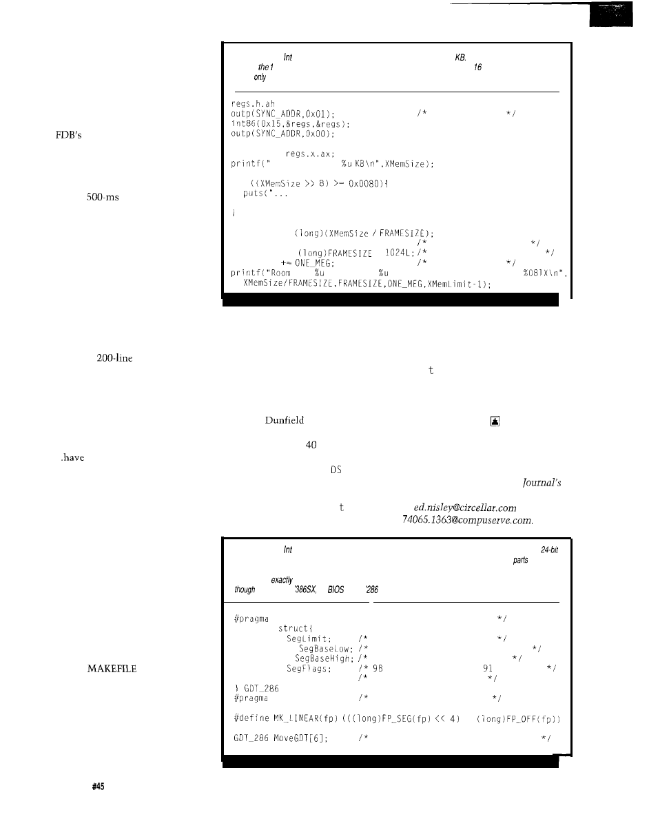
return codes that I simply ignore here,
but you must deal with them in a real
application.
After extended memory is full of
Life generations, the code invokes
Function 87 again to copy the data
back into memory below
1
MB. One of
the
DIP switches controls
whether the data is then copied into
the LCD buffer using
memcpy
or a
nested pair of C loops so you can see
which affects the display least. A
hardcoded
pause between each
slide gives you time to think about
what’s going on.
One megabyte of extended
memory holds 32 generations of 32 KB
each, which works out to
16
seconds
of Life. My system has 6 MB (5 MB
above the
1
MB line) and can store 160
generations, which makes for a longer
show. The low-order byte of DIP
switches sets the intial random
number seed, so you have a choice of
25.5 different slide shows.
Because
panels use only
the low-order nybble of each byte, you
could store twice as many generations
by applying a no-brainer compression
scheme. The Life field has many dead
cells after the first few generations, so
you could probably pick up another
50% by run-length encoding what’s
left..
fun!
Don’t be surprised to find yourself
rooting for clumps of dots as they
expand, contract, and consume each
other. Life is like that..
RELEASE NOTES
The BBS files this month include
the source code and binary files for the
four panels mentioned in the text. The
code is written in Borland C and
processed through Paradigm’s Locate
utility, so copy the BIN files onto a
diskette with the boot loader from
Issue
41
and fire up your LCD.
The code unique to each panel is
in an assembler file with the panel’s
name. The
produces a
similarly named binary on drive A, so
have a diskette with the boot loader
ready when you recompile the code. If
you want to add another panel, use one
of the existing files as a template,
update the MAKEFILE, and you’re all
set.
Listing 6-BIOS 15 Function 88
returns the extended memory size in
This memory starts just
beyond
MB of memory addressable in Real mode. Because AX has on/y bits, the function can
report
the first 64 MB of extended memory!
= 0x88:
mark the query
XMemSize =
BIOS reports
if
on a 386SX you can't have that much, so it's ignored");
XMemSize = 0;
XMemLimit =
truncate limit to a
XMemLimit *=
*
multiple of the slide
XMemLimit
above the line
for frames of KB each between %081X and
You also get my version of
Paradigm’s C 0 N SO
L E . C
file. I replaced
their demo code with BIOS serial code
to support simple console I/O. If you’re
using Locate, you must also set up the
FARH EAP
constant (I used 0x8000) to
allocate a decent-sized far heap for the
program’s work buffers.
values are different the interrupt
handler is saving and restoring its own
? t
emp,
but with no ill effect.
He mentioned that the compiler
uses ?
emp
in certain complex
operations, so you can’t just throw it
out. My examples were simple enough
that they didn’t use it, but real code
would have trouble.
Dave
politely pointed
out that the Micro-C problem I’d
mentioned in Issue
was entirely of
my own making. The Micro-C inter-
rupt handler should load
with its
own data segment,
then
save ?
temp.
If
the interrupted routine shared the
same data segment, the old ?
emp
is
saved and restored correctly. If the
DS
Ed Nisley, as Nisley Micro Engineer-
ing, makes small computers do
amazing things. He’s also a member of
the Computer Applications
engineering staff. You may reach him
at
or
Listing 7-BIOS
15 Function 87 copies memory between any two addresses in RAM, specified as
linear values rather than the familiar segmentoffset pairs used below 1 MB. You must fill out
of the
Global Descriptor Table Function 87 will use when entering Protected mode, although the references
disagree on
what the GDT must contain. The GDT is an array of the structures shown here. Even
the CPU is a
the
uses a
format GDT for compatibility
with
the original PC/AT.
option -a-
/*
typedef
WORD
W O R D
BYTE
BYTE
WORD Reserved:
option -a.
structure must be packed
size of segment in bytes
low two bytes of linear address
high byte of linear address
= code, 93 = data, = RO data
reserved, must be zero
restore default setting
+
GDT for BIOS Move Block operation
5 2
Issue
April 1994
The Computer Applications Journal
Listing
addition the (obvious/y) necessary source and destination addresses in
this code
the segment length and access
even though they’re not required on my system. 1 on
marks
journey through Protected mode; if LED remains your CPU off
The code to copy data from extended memory is similar: just interchange the addresses.
=
= 0x93;
=
=
=
= 0x93;
=
target
SegBaseHigh =
set up zeros
get current seg regs
regs.h.ah = 0x87:
move block
regs.x.cx =
number of words
regs.x.si =
offset of GDT
sregs.es =
segment
mark the move
shazam!
stored at
+=
*
step to next block
Crystaloid Electronics Company
produces a booklet titled “Liquid
Crystal Displays: A Primer” that
explains how various types of
LCD panels work and explores
system design tradeoffs. It’s
intended for OEM customers
who must select or specify a
panel, so it’s not too technical.
Contact them at 5282 Hudson
Dr., Hudson, OH 44236, (216)
655-2429, fax (216) 6552176.
Pure
has the
complete Firmware Development
Board schematic, as well as
selected parts. Write for a catalog:
13 109
Old Creedmoor Rd.,
Raleigh, NC 27613. Phone or fax
(919) 676-4525.
410 Very Useful
411 Moderately Useful
412 Not Useful
CONTROLLERS
Iota continues its strategy of developing small
powerful controllers with its new line using the
and
microcontrollers.
We have also developed our own
which runs in the
Several software tools
are available to ease the development process.
We offer:
l
peripherals
l
Complete Development Packages
l
Powerful controller BASIC for the
l
A BASIC-752 Simulator
Voice:
Fax:
Iota Systems, Inc.
POB 8987
l
Incline Village, NV 89452-8987
Flat panel interfacing made simple!
Just
install the modules and you are ready for action!
SVGA Flat Panel Controller, Interface Card and Touch Screen Module
Super VGA Controller
OEM
price
at
$289
+
IBM-AT 16 bit bus compatible
Supports LCD, EL, Plasma,
and
Panels
+ Supports panel resolution
to 1,280 1,024
+ 256K VRAM 256K 4 Frame Accelerator or 512K Opt.
Optional touch screen communication interface
Flat Panel Interface Card
OEM
price
at $79
Supports 640 480 and higher resolution panels
+ Built in CCFL backlight
and LCD bias supply
+ Brightness and contrast controls
Extended cable length support
Touch Screen and Controller
OEM
price
$249
+ Analog
Resistive, resolution 1,024 1,024
+ 9600 baud
or COM2
Technologies, Inc.
708-559-9291
115
Avon Rd, Northbrook, IL 60062-1335
fax 708-205-9411
The Computer
Issue
April 1994
53
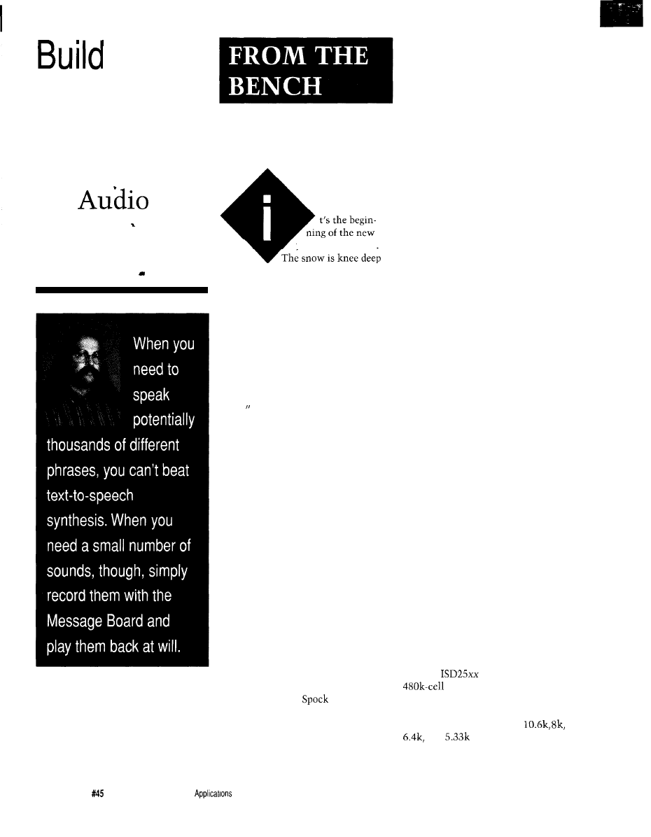
the
Message
Board
An
Record/
Playback Unit
Jeff Bachiochi
year as I write this.
and the oil trucks are as busy as
spring’s honey bees. I just removed our
Christmas tree’s skeleton from the
house. Not a needle left on it. I re-
member the devotion to that tree back
in December when we picked it out.
Choosing a Christmas tree is
always an experience. The festive
spirit usually peaks as we drive toward
our destination, the local tree farm.
After an hour or two of “nope, too
short, “that’s lopsided,” or “this one’s
missing branches,” we have totally
lost the spirit of the season and aren’t
on speaking terms.
I
know this
happens to you; I’ve heard you arguing
over in the next row of trees!
Things turned out a bit different
this year. While picking up a few
supplies at the local building supply
warehouse, the kids noticed they were
selling trees. “Let’s look,” they begged.
“A Canadian orphan,” I thought.
And there it was, the tree. We couldn’t
believe it: everyone was in agreement.
I quickly paid for it while I thought
over and over, “Still on speaking terms
and the tree was chosen.”
The ornaments were hung by the
children with care, in hopes that all on
their lists would soon be there. Each
one of us has our own ornament.
I
have Star Trek’s shuttle craft which
repeats a canned message. “Shuttle
craft to Enterprise.
here. Happy
holidays. Live long and prosper.”
“I’ve swept quite a few needles
from the floor so far,” Beverly prodded.
“Must be the initial shock,” I
surmised. For the next week it rained
evergreen spikes.
“That tree shouldn’t be shedding
like this,” she needled. “We need a
new tree.”
“Look, it’s only a few days ‘til
Christmas; it will be fine.” I argued,
“Besides, look at how well you can see
all the ornaments!”
“Everything must be perfect.” Her
voice became strained, “You know we
are having your family over for
Christmas dinner this year.”
I thought to myself, “Oh yeah,
you know how a defective Christmas
tree can ruin a party.” I could feel the
spirit making a run for the door. But it
wasn’t too late.
After examining the true meaning
of Christmas we exchanged no harsh
words, only gifts, and had a great
Christmas in spite of the naked tree.
Its boughs now bare, it sits upright,
outside in the snow. Suet and seed
decorate its branches. And you know,
the birds haven’t complained once.
COMPLAINT DEPARTMENT
Many readers of this column were
disappointed when the circuitry for the
HCS-Voice text-to-speech board was
not revealed (“Updating TIM for the
HCS II,” October ‘93). We felt that
since we couldn’t give away the
licensed software, having the schemat-
ics would only cause distraction. The
board is available as a kit. Even though
it wasn’t covered in detail in an article,
its text-to-speech capabilities make it
my choice for use with the HCS.
Looking for something a bit
simpler you say? This month’s project,
the “Message Board,” uses the new
ISD2500 series of analog record/
playback devices from Information
Storage Devices in a cascade mode to
create an expandable messaging
system. This is the same technology
used in the Shuttle Craft ornament.
ISD2500
The
series devices use a
nonvolatile analog storage
array to provide 45, 60, 75, or 90
seconds of storage depending on the
fixed input sample rates of
and
respectively. DAST
(Direct Analog Storage Technology)
allows analog data to be written
54
Issue
April 1994
The Computer
Journal
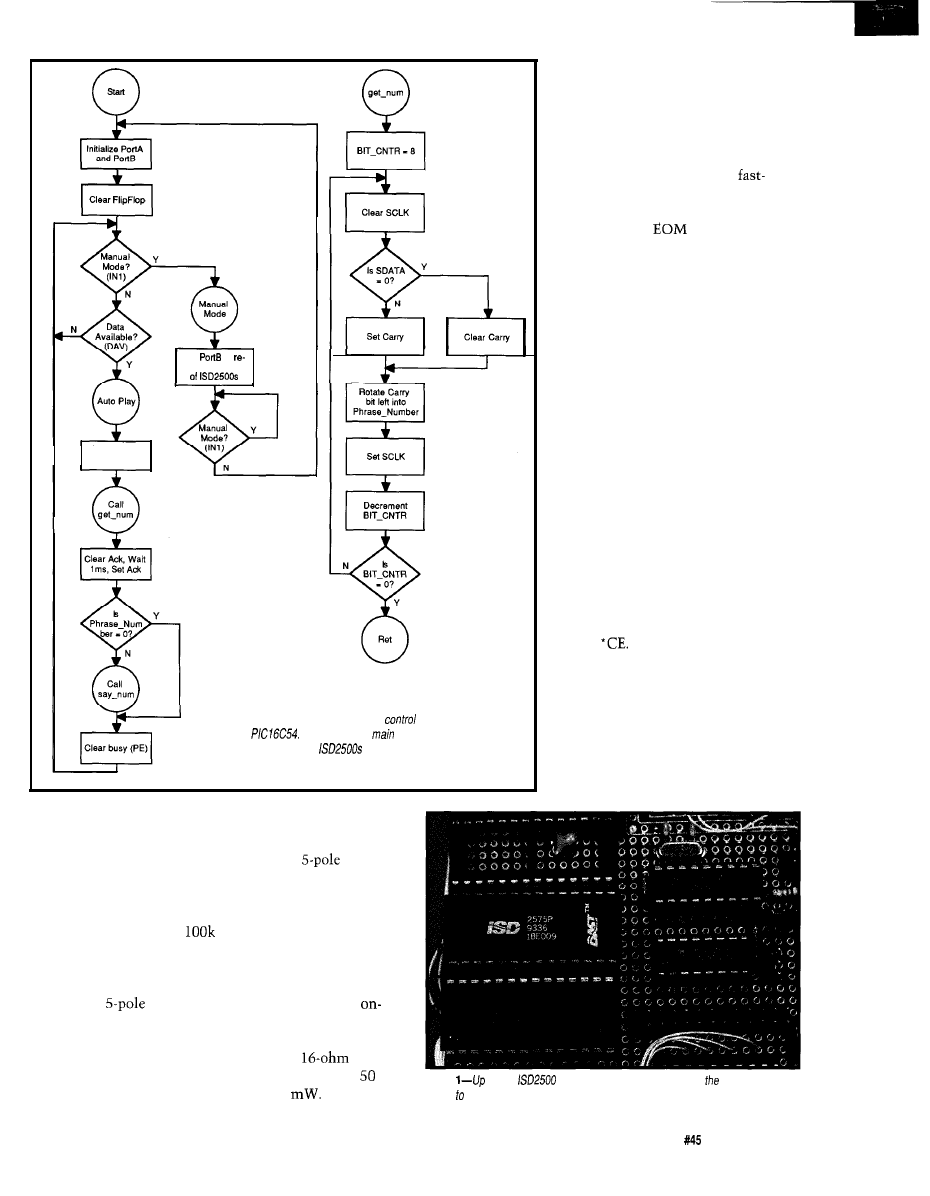
Clear
set Busy (PE)
Set
to
lease all control
Clear SCLK
Figure l--The Message Board’s
code is contained in
a
The processor3
job
is to locate the correct
phrase within the
and handle the playback.
directly into an EEPROM cell without
A/D conversion and to be read directly
from an EEPROM cell without D/A
conversion. This means an increase in
storage density per word. Data reten-
tion can be as much as 100 years while
record cycles can exceed
times.
On-chip peripherais include a
microphone preamplifier with AGC
(automatic gain control). During
recording, a
antialiasing filter
removes any audio components which
approach one-half the sampling
frequency. The analog storage array is
based on EEPROM floating gate
technology and is equivalent to 8 bits
of accuracy.
During playback,
a
smooth-
ing filter helps to
remove the
sampling fre-
quency compo-
nent and restore
the original
waveform.
Finally, an
board amplifier
will directly drive
a
speaker
with up to
OPERATIONAL MODES
Message cueing mode (MO)
provides the ability to step through
recorded phrases without any audio
output. 1’11 be using this mode to allow
a micro to index through a message
base. The cueing is done in a
forward mode which zips through each
message at 800 times normal speed.
The Delete
marker mode
(Ml) will concatenate all message
phrases into a single message. This is
accomplished by eliminating all EOM
markers from all previously recorded
individual messages and adding one
EOM marker to the final message.
Looping mode (M3, M2 is re-
served) continues to replay the first
message without a pause.
The consecutive addressing mode
(M4) prevents the address pointer from
being reset upon an EOM marker. This
provides the facility to record or play
back multiple message phrases within
a single chip. This mode, in conjunc-
tion with the message cueing mode, is
the heart of this solid-state analog
record/playback system.
Level-activated mode (M5) allows
the playback to be terminated by the
rise of the
l
CE line. (Normal operation
would start the message on the falling
edge of
At that point, raising
l
CE
has no affect. The message would end
following an EOM marker.)
The push-button mode (M6)
reduces the external component count
to only those necessary to provide a
simple push-button solid-state tape
recorder. Start/Pause and Stop/Reset
push buttons are all that is necessary
Photo
to four
family
chips may be plugged into Message Board
for up 6 minutes of audio storage.
The Computer Applications Journal
issue
April 1994
5 5
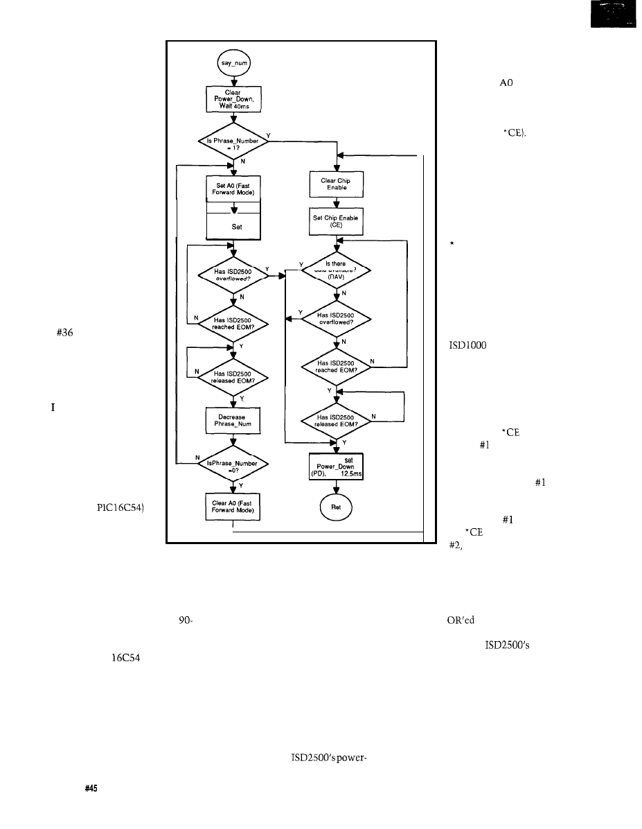
to
provide either record or
playback functions. An
additional switch will
allow record and playback
selection. This simple
mode is limited to a single
message or phrase.
In addition to the
previously mentioned
modes, direct access
addressing can point to the
beginning of any of the 600
possible message segments
within a single ISD2500
device. If you knew the
address of each message,
you could point directly to
it. However, this is
generally not known
except in a sound develop-
ment environment.
See Tom Cantrell’s
“Talking Chips” article in
issue
for more informa-
tion on the older ISDlOOO
series devices.
A MICRO CONTROLS
THE MESSAGE
wanted this message
playback system to be easy
to use, so I use a single
byte [message number) to
indicate one of a possible
255 prerecorded message
phrases to play back. To
accomplish this, I use a
small micro (a
to accept a byte from any
parallel port and perform
the necessary twiddling on
the ISD2500 devices to fast-forward to
the correct message and play it. Notice
I used the plural “devices”; the option
of using multiple devices increases the
overall message storage capability up
to a maximum of 6 minutes (four
second devices). More on this later.
I/O pins on a small micro are
sparse; the 18-pin
has just 12
I/O lines that can be totally consumed
by a parallel connection [including
handshaking). To resolve this, we
must bend over backwards to interface
with the micro. A parallel-loaded serial
shift register requires only two I/O bits
to interface as opposed to the eight
required for directly reading the byte.
40ms
Figure l-continued
Clear Chip
Enable,
Chip
Enable (CE)
data available?
Clear AO.
Wait
To ensure the byte is not missed (this
version of the PIC has no external
interrupts), the data’s strobe is latched
to become a DAV [data available]
signal which is periodically scanned by
the micro. The micro initiates a busy
signal while serially sucking in the
parallel port’s data, then acknowledges
its receipt once the data is digested.
See the flowchart in Figure 1 for the
micro’s code outline.
At the other end of the circuit, the
micro manages four ISD2500 control
functions. The P/R control bit selects
the playback/record mode. The PD
control bit resets the message pointer
and regulates the
down mode. The
l
CE
control bit begins the
record/playback function.
Finally, the
addressing
bit selects message cueing
(fast-forwarding in the
playback mode in combi-
nation with
Two
additional input bits to the
micro are used from the
micro. The
l
EOM signal
indicates the end of a
particular message phrase.
This is the feedback for
cueing up a message
phrase. The second input,
OVF, signals the end of
the storage device has
been reached.
To expand the total
storage capabilities of this
board, I cascade the
ISD2500 devices in a daisy
chain fashion. The earlier
series devices
could not handle multiple
messages straddling the
boundaries of two devices.
Some interesting signal
steering goes on when the
devices are cascaded. For
control, the
input of
device begins a mes-
sage. If the message is
longer than the storage
capability of device
then the
l
OVF output
drops. This output signal
from device is used as
the
input to device
enabling the second
device only after the storage capacity
of the first has been exhausted. *OVF
from the last device is used as feed-
back to the micro. Individual *EOM
outputs from each of the storage
devices are
as feedback to the
micro. These two signals keep the
micro abreast of the
status.
On the audio side, an auxiliary
audio input is directed to the speaker
output whenever the device is not
selected or is in overflow. This is
important. Whenever the second
device takes over its audio output,
which is connected to the first device’s
auxiliary input, it is passed through
the first device’s amplifier. Audio from
56
Issue
April 1994
The Computer Applications Journal
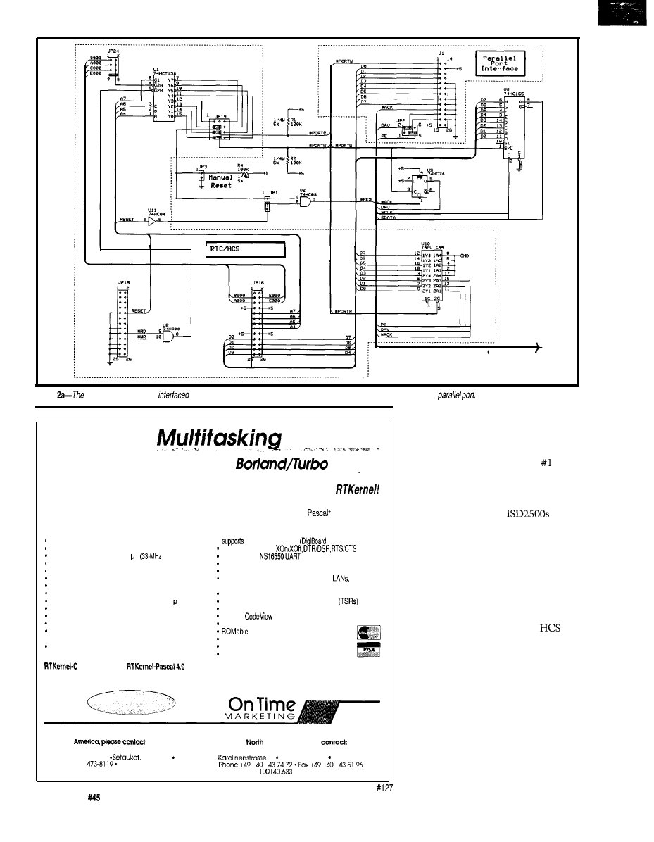
Interface
CONTROL BUS
gure
Message Board can be
to fhe HCS in the same way as the HCS-Voice board, or may be connected to a
Real-Time
with DOS
for Microsoft C, Borland C,
Pascal
Develop Real-Time Multitasking Applications under MS-DOS with
RTKernel is a professional, high-performance real-time multitasking kernel. It runs under MS-DOS or in ROM
and supports Microsoft C, Borland Ctt, Borland/Turbo Pascal, and Stony Brook
RTKernel is a
library you can link to your application. It lets you run several C functions or Pascal procedures as parallel
tasks. RTKernel offers the following advanced features:
pre-emptive, eventiinterrupt-driven scheduling
number of tasks only limited by available RAM
l
up to
36 COM ports
Hostess boards)
task-switch time of approx. 6 s
486)
supports protocols
performance is independent of the number of tasks
full supportof
chip
use
up to 64 priorities
to control your tasks
supports
math coprocessor and emulator
priorities changeable at run-time
fast, inter-networkcommunication using Novell’s IPX
runs under MS-DOS 3.0 to 6.x,
DR-DOS,
time-slicing can be activated
programmable timer interrupt rate (0.1 to 55 ms)
or without operating system
high-resolution timer for time measurement (1 s)
DOS
calls from several tasks without re-entrance problems
activate or suspend tasks out of interrupt handlers
supports resident multi-tasking applications
runs Windows or DOS Extenders as a task
programmable interrupt priorities
semaphores, mailboxes, and message-passing
supports
and Turbo Debugger
keyboard, hard disk, and floppy disk idle times
Kernel Tracer for easy debugging
usable by other tasks
full
source code available
interrupt handlers for keyboard, COM ports, and
no run-lime royalties
network interrupts included with source code
free
technical support by phone or fax
4 . 0 9495
$ 4 4 5
International orders: add $30 shipping and handling.
C Source Code: add $445
Pascal Source Code: add $375
Mastercard, Visa, check, bank transfer accepted.
In
North
LEL Computer Systems
Professional Programming Tools
Outside
America, please
20 Canterbury Court
NY 11733 USA
On Time Marketing
Phone (516)
Fax (516) 331.0706
32 20357 Homburg GERMANY
CompuServe 73313.3177
CompuServe
5 8
Issue
April 1994
The Computer Applications Journal
all devices is daisy chained through
the first device’s speaker output.
Likewise, when in record mode, the
microphone preamp on device is
directed to each of the cascaded
devices, resulting in a simple user
interface for multiple devices. See
Figure 2. Although the
will
directly drive a speaker, I’ve added the
identical audio output circuitry used
on the HCS-Voice board to maintain
compatibility with the DTMF board.
SEND A BYTE, SPEAK A PHRASE
A single-byte transfer starts the
message playing. Although designed
with the same interface as the
Voice, a PC’s parallel port can alterna-
tively be used to cue up a message and
begin playback. Prerecorded messages
l-255
are invoked by writing that
particular binary value to the Message
Board’s parallel port. Any message can
be interrupted prematurely by sending
another message number (the new
message begins immediately). Select-
ing phrase zero stops the speaking
altogether.
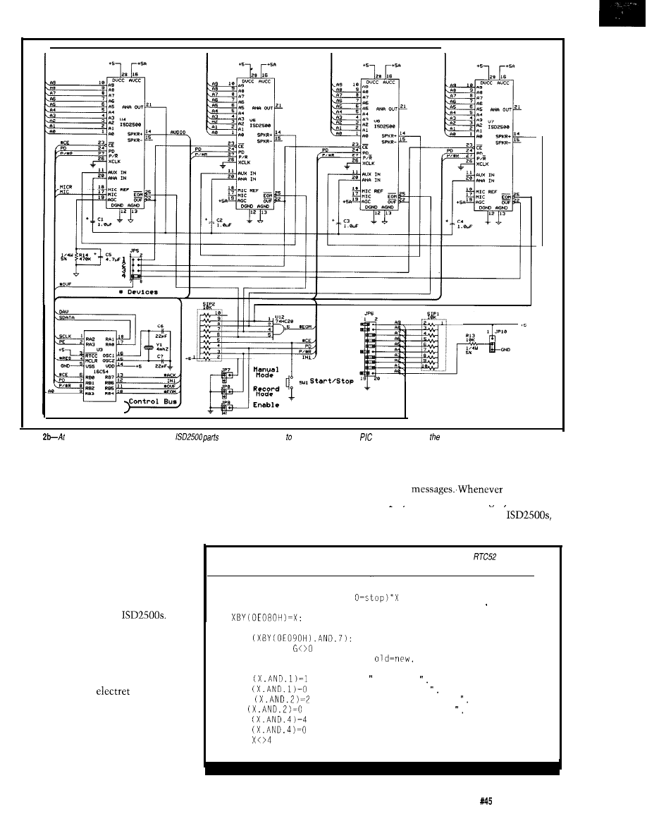
Figure
the core of the board is up to
four
capable of holding up 6 minutes of audio. A
processor controls show.
PRERECORDING
inserted. You may continue to record
The Message Board can’t speak
additional messages until the OVF
unless you provide it with a message
LED comes on. At this point the
base. I suggest you start by writing
storage area is filled and will not
then reinsert the “Enable” jumper.
You are now ready to rerecord all of
your
the record/
playback mode is changed. the address
down a list of all the messages (or
sounds) you wish to include. Practice
repeating them a few times until you
feel comfortable. The Message Board
can be put into manual record mode
using the following steps:
Insert the “Manual Mode” jumper
to instruct the micro to release all of
the control lines to the
Insert the “Record Mode” jumper to
place the ISD2500 devices into the
record mode. Insert the “Enable”
jumper to remove the ISD2500 devices
from power-down mode.
Now plug an
microphone
into the audio input jack. You may
begin recording the first message on
your list by holding down the “Start/
Stop” button until you are finished
with the first message. Each time the
button is released, an EOM marker is
accept additional input. If you wish to
pointer is reset within the
rerecord all the messages, remove and
requiring you to start over if you wish
Listing l--The
Message Board is a memory-mapped device when plugged info an
and can be
controlled directly from BASIC.
10 PRINT
20 INPUT "Phrase ii (l-255,
30 PRINT "Hit any key to cancel status reporting"
40
REM Write phrase number to port
50 Y = 255: REM Initialize to a nonstatus value
60 X =
REM Get status from port
70 G = GET: IF
THEN GOT0 10: REM Key pressed?
80 IF X=Y THEN GOT0 60: REM If
skip status print
90 Y = X: REM Update old status
100 IF
THEN PRINT
Busy
110 IF
THEN PRINT "Not Busy
120 IF
THEN PRINT "Data Available
130 IF
THEN PRINT "Data Captured
140 IF
THEN PRINT "Acknowledged"
150 IF
THEN PRINT "Working"
160 IF
THEN 60: REM This value indicates end of phrase
170 GOT0 10
The Computer Applications Journal
issue
April 1994
5 9
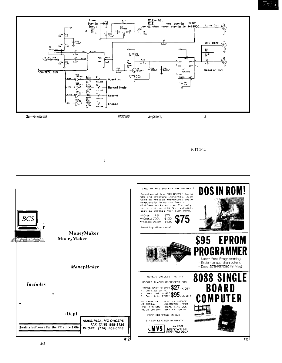
NOTE: Use
NOT both
U s e
w h e n
is
Figure
microphone is used to record audio. Even though the
chips include
one is included on the board so functions the same as the
HCS- Voice board.
to correct an error or add more mes-
sages.
You may manually review your
messages by removing both Record
mode and Enable jumpers and reinsert-
ing only the Enable jumper (playback
mode). Each time the Start/Stop
button is pressed, a message will play.
When you are pleased with the
session, remove the “Enable,” “Record
Mode,” and “Manual Mode” jumpers.
The micro has now regained control
and you may command the Message
Board to speak.
have provided a couple of short
no-frills programs to test out the
Message Board once you have filled its
mind with message phrases. The
program in Listing 1 uses the Message
Board as a memory-mapped I/O device
with an
Notice the “Parallel
Port Interface” in the schematic is not
necessary when the Message Board is
to be used with either the RTC or HCS
EARN $5000 PER MONTH
With your home computer!
BCS
Spending too much on your computer?
Now it’s time to let it earn good money
for you! Our two successful Software
Packages,
Volume-l
and
Volume-2 will
give you all the insider information you
need to start and succeed with your own
PROFITABLE BUSINESS Part-Time at home!
Your cost for all this extra income?
Only $29.95 for
Volume-l
For BOTH VOLUMES NOW send just $39.95 !!!!
AND GET NEW 300 PAGE MANUAL FOR 1994
FREE Talking Demo Disk and
3 BIG Catalogs full of more Money Making ideas!
We
always pay
postage *
Please specify disk size or we ship 3.5”
Check, Credit Card, or M.O. to:
BUSINESS COMPUTER SYSTEMS, INC.
46-16 65TH PLACE
M2
WOODSIDE, N.Y. 11377
60
Issue
April 1994
The Computer Applications Journal
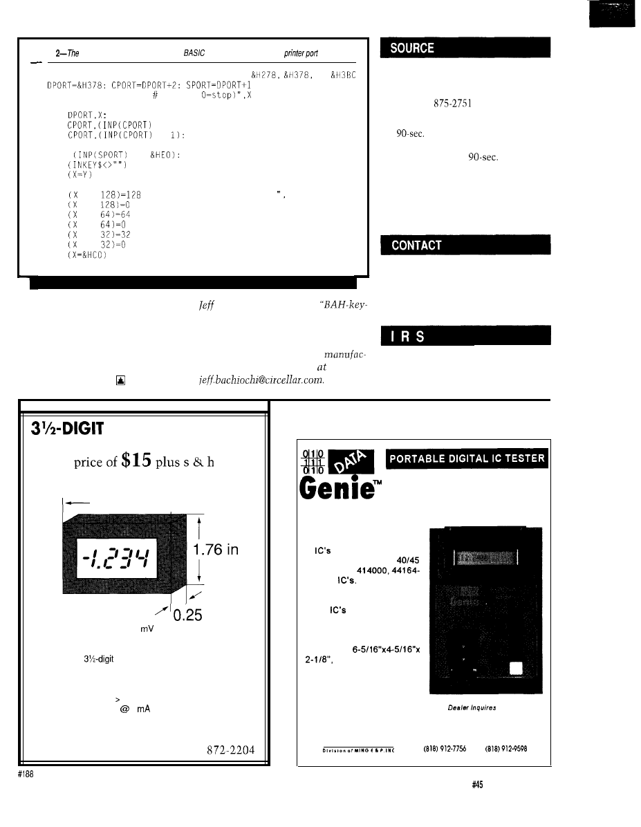
Listing
board may also be controlled from
when plugged into a PC’s
10
20
30
50
60
70
80
90
REM Possible printer port addresses are
or
PRINT: INPUT "Phrase (l-255,
PRINT "Hit any key to quit status reporting"
OUT
REM Write phrase value to the data port
OUT
AND 254): REM Strobe low
OUT
OR
REM Strobe high
Y = 255: REM Initialize to an impossible status value
100 X =
AND
REM Read status port
110 IF
THEN GOT0 30: REM Any key exits status routine
120 IF
THEN GOT0 100: REM If old=new, skip status printing
130 Y = X: REM Update old status
140 IF AND
THEN PRINT "Data Accepted
150 IF AND
THEN PRINT "Data Available",
160 IF AND
THEN PRINT "Data Acknowledged".
170 IF AND
THEN PRINT "Processing Data",
180 IF AND
THEN PRINT "Playback Busy"
190 IF AND
THEN PRINT "Playback Not Busy"
200 IF
THEN GOT0 30: REM Playback has finished
210 GOT0 100
system controllers. The program in
Bachiochi (pronounced
Listing 2 uses GWBASIC to write
AH-key”)
is
an electrical engineer on
directly to your PC’s parallel port. The
the Computer Applications Journal’s
“RTC/HCS Interface” is not needed if
engineering
staff.
His background
you
wish to use the Message Board
includes product design and
stand-alone with a printer port.
turing. He may be reached
Happy messaging.
Circuit Cellar Kits
4 Park St.
Vernon, CT 06066
(203)
Message Board (full kit] with one
storage device . . . . . . $149.00
Message Board (assembled and
tested) with one
storage
device . . . . . . . . . . . . . . . . . . . . . . . . . . . . . $199.00
Individual ISD chips are
not
available from Circuit Cellar
(except with purchase of the
Message Board).
Information Storage Devices
2841 Junction Ave.
San Jose, CA 95134
Tel: (408) 428-1400
Fax: (408) 428-1422
413
Very Useful
414 Moderately Useful
415 Not Useful
LCD PANEL METER
-Available now at an unheard of
N e w ! N o t s u r p l u s !
2.72 i n - )
Specifications:
in
Maximum input: f199.9
additional ranges provided through
external resistor dividers
Display:
LCD, 0.5 in. figure height,
jumper-selectable decimal point
Conversion: Dual slope conversion, 2-3
readings per sec.
Input Impedance: 1 OOM ohm
Power: 9-l 2 VDC
1
DC
Circuit Cellar, Inc.
4 Park Street, Suite 12, Vernon, CT 06066
Tel: (203) 875-2751
Fax: (203)
EXPRESS SERIES
HT-28
The Data Genie HT-28 is a
convenient way of testing Log-
ic
and DRAM’s
Tests
most TTL 74, CMOS
and DRAM’s
441 000
The HT-28 can also identify
Logic
when a non-stan-
dard part number is used or
if the product ID has been
removed. The HT-28 is com-
pact in size,
and can be operated
from an AC adaptor or up to
600 hours on 4-“AA” alkaline
batteries.
Welcome
M I N G
17921 Rowland St.
M i c r o s y s t e m s
City of Industry. CA 91748
TEL
FAX:
The Computer Applications Journal
Issue
April 1994
61

When The
SHARC
Bites
Tom
proaches, it’s time
d and head over to
Santa Cruz to catch a few curls. If
you’re ever there, make sure you stop
by the Surfing Museum at Lighthouse
Point and check out the gallery of
surfboards that paid the ultimate price
as toothpicks for sharks.
Now, a surfboard is very hard,
easily surviving-as I know first-
hand-being run over by a car, falling
off one at freeway speeds, hammering
a tent stake, and so forth. The samples
in the surf museum are striking, not
being chewed, mangled, torn, or bent.
Rather, the part now serving as
roughage in some sharks weight-loss
plan is simply gone-cleanly removed
as with a scalpel.
Sometimes when I’m waiting for a
wave, an inquisitive seal will pop
how cute, eh! However, any feelings of
affection are quickly tempered by the
realization that when I’m in a black
neoprene
I look a lot like a
well fattened seal-favored appetizers
of our predatory friends. Makes me feel
kind of like I’ve got a flashing neon
“Eat At Tom’s” sign on my forehead.
Circling the waters of the RISC
versus DSP controversy is a JAWS (Just
Another Wild Semiconductor) of a
different sort: the 21060 SHARC from
Analog Devices.
The debate that rages on is
whether regular RISC CPU chips can
handle signal processing chores as well
as
(see “Is the Am29050 a
bearing Animal?” in the September ‘93
issue). Alternatively, the question
could be whether DSP chips can
handle regular processing as well as
As in most religious wars it’s a
case of
they stand is where
they
that is, the right answer (and
question) correlates highly with what a
particular outfit is trying to sell you.
Like a bullet manufacturer, you
stand to benefit from this war, whom-
ever wins. Both camps are tuning,
tweaking, and packing transistors in a
feverish effort to achieve at least a
temporary advantage. Notably, most
new (Not-So-) RISC chips are appear-
ing with built-in MAC (Multiply
Accumulate) instructions to speed up
“DSP operations.”
So, is the SHARC, like its ocean
going counterpart, the ultimate
predator? Or, as the
believe, is
it just a big dummy with lots of teeth,
as wimpy as our local hockey team of
the same name? They’re so bad, locals
were cheering their quest for the
record-of most consecutive losses!
IVY LEAGUE
SHARC, standing for “Super
Harvard Architecture,” joins ranks
with Superscalar and Superpipeline (I
just call ‘em Superdupers) in the
performance-at-any-price quest for
king of the hill bragging rights.
Most of the microprocessors
you’re familiar with-such as the
‘x86,
etc.-rely on a single bus for
both instruction and data delivery.
By contrast, a Harvard architec-
ture uses two separate buses-one for
instructions and one for data-allowing
simultaneous instruction fetch and
data read/write. For full parallel
operation, each data bus has a corre-
sponding address bus. These systems
have four buses, which are often
referred to as
PA, DA, PD,
and
DD
(program address, data address,
program data, and data data, respec-
tively).
The problem with lots of buses is
they require lots of pins, the main
reason Harvard chips are as rare as
Great Whites. However, besides pin
count, there are other concerns about
the suitability of Harvard architectures
for general-purpose processing.
For instance, if instruction and
data buses are physically separate,
normally trivial issues such as loading
a program into memory or embedding
62
Issue
April 1994
The Computer Applications Journal
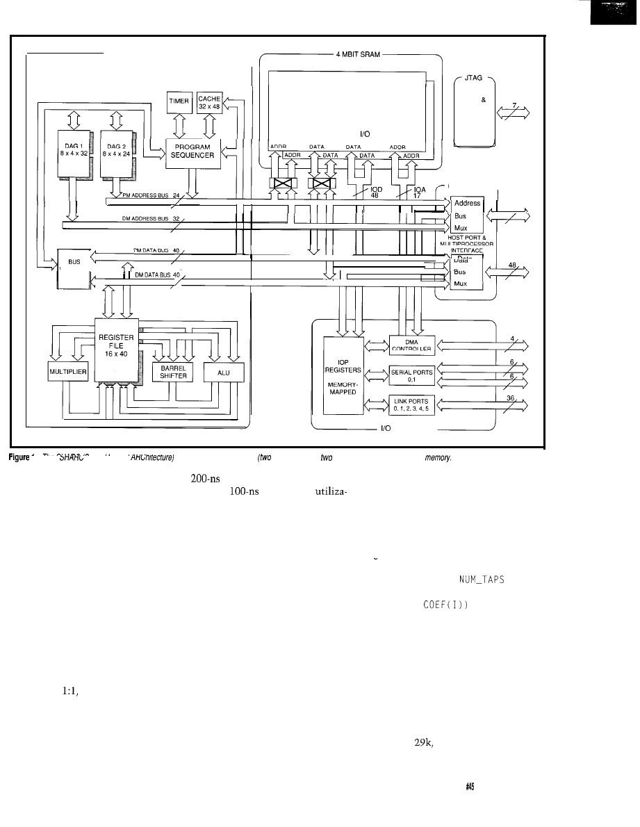
C O R E P R O C E S S O R - - - - ,
TWO INDEPENDENT 2 MBIT BANKS,
DUAL-PORTED
TEST
EMULATION
PROCESSOR PORT
PORT
EXTERNAL PORT
3
2
,
CONNECT
I
I I
I I I L
I
I I
I I I I
PROCESSOR
I
-
I
ne
(super narvara
sports tour separate buses
for address and
for data) plus loads of on-chip
EPROM while data ops access a
design by performing an instruction
speedier
SRAM? Full
and
two
data ops at once.
tion of all bus bandwidth requires that
Yes, the cache is quite small (32
instruction and data access times be
instructions), but remember that the
equal.
core of typical DSP routines is a tight
THROWN FOR A LOOP
multiply and accumulate loop that
goes something like:
constants in a program ROM may be
problematic since both require
accessing (the former writing, the
latter reading) data in program
memory. Typically, special instruc-
tions such as LOAD CONSTANT (i.e.,
do a load from the instruction
memory) or bus override/swapping
schemes are needed.
Another concern is making sure
you get full “bang per buck” out of the
bandwidth. Yes, performing an
instruction and data access every cycle
is twice as fast as doing them one after
the other, but how likely is it that
your program acts that way? Often
instruction fetches and data accesses
don’t match
meaning all those
pins you paid for aren’t being fully
utilized.
In a similar fashion, asymmetric
access times can prove troublesome.
What if instruction fetches are out of a
Having populated the anti-Harvard
credentials are clearly established by
the four buses previously described.
army with straw men, now let’s see
how the SHARC (Figure 1 and Photo 1)
chews them up.
The chip starts with the existing
21020, a high-end (40 MIPS) 32-bit
floating-point DSP, whose Ivy League
Inclusion of an instruction cache
is the first feature that qualifies the
SHARC for “superness.” When
instructions are available from cache,
the PD bus is free to fetch data along
with the DD bus. Thus, the SHARC
one-ups a regular “non-super” Harvard
loop is more “data bound” than typical
non-DSP code, meaning there are
relatively few instructions compared
to data accesses instead of vice-versa.
FOR I = 1 TO
The instruction/data parallelism of
DSP code is well served by the Harvard
ACC = ACC + (DATA(I) *
architecture (which helps explain why
the AMD
a Harvard design,
performed so well in the article I
NEXT I
By the way, notice that this tight
The
Computer Applications
Journal
Issue April1994
63
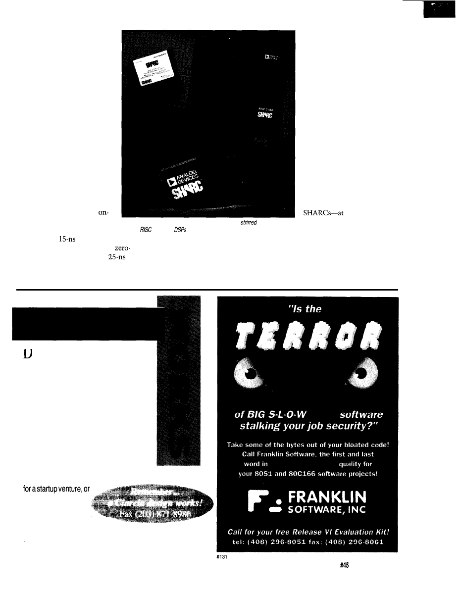
mentioned above). By offering
two data ops per cycle, the
SHARC is presumably well
balanced for these tight
loops-ideally, all three buses
are active all the time.
By far the most exciting
feature of the SHARC is the
inclusion of a whopping 4
megabits of SRAM. Consider-
ing that 4-megabit SRAM
chips are themselves barely
peeking out of the lab, it
wouldn’t be unreasonable to
consider the SHARC a smart
memory chip rather than a
DSP. Rather a case of the tail
wagging the shark, wouldn’t
you agree!
(six from I-cache and five each
on the PD and DD buses) at
40 MHz yields a whopping
640 megabytes per second of
bus bandwidth. This kind of
bandwidth would be very hard
[and expensive) to achieve if
the memory-and all those
bus lines-had to go off-chip.
While it is outrageous,
packing so much memory
chip yields equally dramatic
benefits. The SRAM is very
fast, with the
or so
Photo l-The 21060
SHARC from Analog Devices has
up a debate
between
chips and
and which
of these handles signal processing
better.
Hey, with more buses
than a Greyhound terminal,
why not go for the gusto? The
SHARC adds an I/O processor
with yet another bus. The
IOP contains a lo-channel
DMA controller, clocked
serial ports (typically used to
connect the A/D and D/A
subsystems) and link ports
which can connect up to six
a speedy 240
MB/second-in a multiproces-
sor configuration.
access time needed to meet the
mainly related to memory bandwidth
THANKS FOR THE MEMORIES
wait-state requirement of the
(40
rather than instruction set complexity
While providing speed and saving
MHz) cycle time. Despite the claims of
or other architectural embellishments.
pins, the on-chip memories are
zealots, in my opinion performance is
The SHARC, shipping up to 16 bytes
cleverly organized to overcome some
oes your Big-Company marketing
department come up with more ideas
than the engineering department can
cope with? Are you a small company
that can’t afford a full-time engineer-
ing staff for once-in-a-while designs?
Steve Ciarcia
and the
Ciarcia Design
Works
staff may have the solution. We
have a team of accomplished program-
mers and engineers ready to design prod-
ucts or solve tricky engineering problems.
Whether you need an on-line solution for
a unique problem, a product
just experienced con-
sulting, the Ciarcia
Design Works is ready
to work with you. Just fax me your
problem and we’ll be in touch.
The Computer Applications Journal
Issue
April 1994
6 5
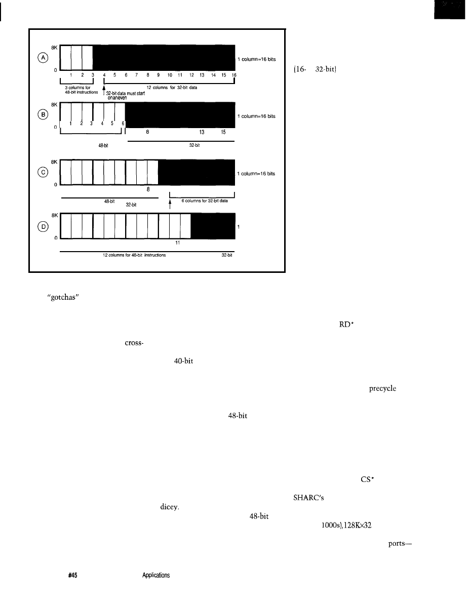
column
6
7
9
10
11
12
14
16
I
6 columns for
instructions
IO columns for
data
1
2
3
4
5
6
7
9
10
11
12
13
14
15
16
I
I
9 columns
for
instructions
6 columns for
data
data must start
on an even column
column=16
bits
1
2
3
4
5
6
7
6
9 10 12 13 14 15 16
4 columns for
data
Figure 2--Memory
configurations
for
the SHARC.
of the
associated with
Given that code and data can both
Harvard designs.
reside in either of the two independent
For instance, the previously
mentioned program load/constant
2-megabit blocks, a basic concern is
problem (i.e., accessing instruction
memory as data) is handled by
how the allocation can be divided. A
bars so that either program or data
memory may be accessed via either
bus. Indeed, both can be accessed from
simple-minded scheme might just split
one of the buses, but the non-Harvard
it in half, or otherwise arbitrarily
penalty (i.e., accesses are back-to-back
rather than in parallel) is automati-
define it according to the chip design-
cally incurred. Wise programmers will
allocate memory to fully utilize all bus
bandwidth. For instance, in the
er’s whim. Naturally, whatever they
previous code fragment the instruc-
tions should be in cache, the coeffi-
cients (which are constants during the
life of the loop) in instruction memory,
and the data being worked on (i.e., the
signal) in data memory.
choose would be just slightly off from
your application’s needs leading to
headaches and wasted RAM.
All this switching and allocating
is complicated by the fact that the
instruction size is 48 bits while data
types
include 16-bit integers and 32-bit
and
floating point.
Similarly, mixing 40-bit and 32-bit
The chip goes to great lengths to
data in the same block would seem
make packing and moving stuff around
easy. Each 2-megabit block of RAM is
physically organized as 16 columns,
However, through wasting a
each 16 bits, in 8K rows. When
byte for each 40-bit value (a
mixing, for example,
instruc-
tions and 32-bit data in the same bank,
the instructions call for three contigu-
access is used), mixing is allowed
ous columns while the data uses two.
Figure 2 shows the possible combina-
thanks to bus switching logic which
tions of 48-bit instructions and 32-bit
routes the access via the instruction
data. Despite AD’s best efforts, notice
the loss of a column in cases A and C.
bus.
66
Issue
April 1994
The Computer
Journal
Mixing 16-bit and 32-bit data is
naturally more straightforward. A
RAM block is actually allocated two
memory spaces, so the type of transfer
or
is simply determined by
which space is accessed.
All this shuffling, switching, and
sizing may sound kind of grim, but
actually AD has done an admirable job
of dealing with the inevitable granular-
ity and access restrictions posed by the
Harvard scheme. Indeed, a little tricky
programming-such as dynamically
changing the RAM configuration
bits-can even get around some of
these, though the data sheet warns
that an “in-depth” understanding is
required to stay out of trouble.
MILD-MANNERED MAINFRAME
Fittingly, this Superchip of steel is
surprisingly mild-mannered on the
surface. Since so many buses-and all
their messy control logic-are on-chip,
the external interface is refreshingly
straightforward (Figure 3).
All the Harvardness is kept on
chip, so to the outside world the
SHARC looks like a regular single data
bus system. The address bus (32 bits)
and data bus (48 bits) access the
external world in a conventional
manner using
and WR* pins. Four
MS
l
(memory select) pins are provided
to enable external memory or I/O
devices. If necessary, ACK acts as a
ready input to inject wait states.
However, an on-chip wait-state
generator does an excellent job, even
providing for selectable
(to
avoid bus contention) and/or postcycle
(to meet address/data hold time) waits.
Though the chip doesn’t directly
drive DRAM
S
, it does give an external
DRAM controller the hooks to support
page-mode (PAGE pin) and synchro-
nous (ADRCLK pin) devices.
For host processor access, the bus
“turns around” and becomes a slave to
the CS* input. When
is asserted,
an external CPU can access the
internal memory and I/O
registers freely. Indeed, the SHARC
makes a pretty nifty, though expensive
($296 in
SRAM.
Similarly, on-chip resources can
be accessed via the six “link”
synchronous nybble-wide ports that
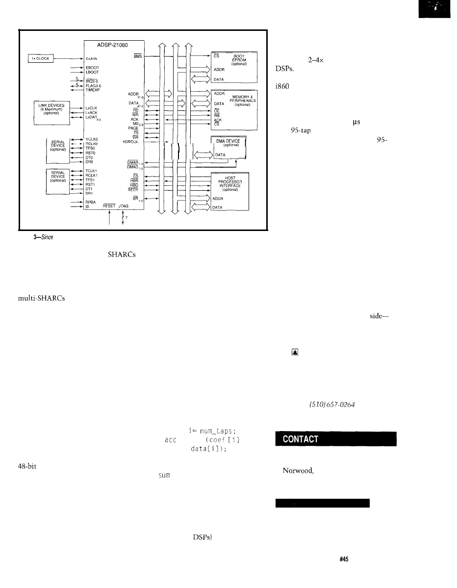
EPROM
ADDR
DATA
Figure
the SHARC has so many of its buses on the chip, external infer-facing is much easier fhan it could be.
serve
as
the basis for ganging
up on a stubborn problem. Portions of
each SHARC’s address space are
mapped into a “global” memory, in
essence combining the resources of
into one logical
machine.
The JTAG (Joint Test Access
Group) port is appearing on more and
more micros. It’s kind of a clocked
serial port that gives access to the
device internals for testing and
debugging. JTAG is the hook used by
the EZ-ICE emulator which combines
a Windows-based front end with most
of the hardware control (except real-
time trace) of a traditional (and more
expensive) ICE.
Based on SRAM, the SHARC
needs a way to clear the cobwebs on
power-up. Figure 3 shows how a
simple x8 EPROM can do the initial
dirty work-a more pleasant prospect
than the six boot ROMs the SHARC’s
instructions would otherwise
demand.
However, AD went further by
anticipating the in-system program-
mable trend I covered a few issues
back. So, the SHARC can also be
“booted” from a host processor or even
via the link and JTAG ports. Oh yeah,
it can also boot from external memory,
so if you want six boot ROMs, you got
‘em.
BENCHMARKBROUHAHA
For development, AD offers a
GNU-based C compiler package
including assembler, simulator, and so
forth for a reasonable $995. In fact, AD
has been heavily involved with
something called NCEG: the Numeric
C Extensions Group. The extensions,
which support DSP applications with
array operations, looping, circular
(buffer) pointers and so on, have been
incorporated in the latest release (2.4)
of the GNU C compiler.
A Numeric C version of the
previous example looks something
like:
iter
= sum
*
Notice the i t e r loop designator and
the array operator-shades of
APL!
You may argue it doesn’t make
the coding a heck of a lot better, and
you’re right. Actually, these exten-
sions are really designed to help the
compiler generate optimized code for
machines (like
that support
looping, arrays, and so forth in hard-
ware.
AD’s own benchmarks claim the
SHARC is
faster than competing
The only benchmark versus
RISC is a lk complex FFT against the
which the SHARC performs 40%
faster (0.46 ms vs. the RISC’s 0.76 ms).
But the article I cited above
showed the AMD 29050 was 15 %
faster than the ‘860 (2.78 vs. 3.3 us)
for a
FIR filter. Interestingly,
AD’s own benchmarks include a
tap FIR filter as well at 2.5 us.
Now, I certainly don’t have
complete benchmark information, so
this could all be apples versus oranges,
and besides, everyone knows bench-
marks can be used to promote many
versions of the truth. Nevertheless,
I’m getting the feeling that, while the
SHARC may be on top today, the RISC
versus DSP battle is far from over.
BLOOD IN THE WATER
Did you know that sharks don’t
have the adjustable bladders lesser fish
use for flotation. Rather, the needed
buoyant gases are generated as a
byproduct of digestion. The hungrier a
shark gets, the harder it has to work to
stay afloat.
Get the point? Whichever
RISC or DSP-you’re on, it’s clear the
high-stakes battle for micro supremacy
is, as for a shark, an eat or die proposi-
tion.
Tom Cantrell has been an engineer in
Silicon Valley
for
more than ten years
working on chip, board and systems
design and marketing. He can be
reached at
or by fax at
(510) 657-5441.
Analog Devices, Inc.
One Technology Way
MA 26062
(617) 461-3881
Fax: (617) 821-4273
416
Very Useful
417 Moderately Useful
418 Not Useful
The Computer Applications Journal
Issue
April 1994
6 7
Who’s in
Control?
John Dybowski
t could be said
that what distin-
computers from their
office-bound counterparts is the fact
that the embedded variety are prima-
rily designed for unsupervised opera-
tion. These things are forever finding
their way into potentially troublesome
situations where they are either
dispersed about remote locations or
placed into seemingly inaccessible
predicaments. In any case, it seems
wherever they end up the electrical
and environmental conditions are
usually less than favorable. In spite of
these difficulties, we assume these
devices will operate for extended
periods without the need for human
intervention.
Many different applications can be
served, but the most demanding casts
the embedded computer in the role of
a system controller. Should such a
control-oriented system malfunction,
the results can range from mildly
irritating to utterly destructive; there’s
nothing worse than a system control-
ler running out of control. In the
majority of cases, this loss of control
can be attributed to electrically hostile
conditions, and some external event
can be blamed for the system malfunc-
tion. However, it pays to keep an open
mind since the culprit may be indica-
tive of some design inadequacy.
One of the worst offenders is the
typical RC processor reset circuit. You
will, no doubt, experience no trouble
using such a circuit throughout the
course of your product development.
But chances are good that once you’ve
moved your system away from the lab
bench, you may begin to experience
new problems. Remember: it’s an
embedded controller’s lot in life to be
around equipment that wreaks havoc
with the power grid. In such a setting,
it’s not uncommon to find out that
your controller checks out every time
some big motor kicks in. Apparently
what’s happening here is that the
power dips to a point where loss of
regulation occurs. Once drops out
of
all bets are off. Unfortunately,
a simple RC reset circuit that works so
well on the lab bench is sufficiently
primitive to be of no use at all in such
a situation. Obviously, one way to
solve this problem is to incorporate a
decent reset circuit into the
design...but it pays to look further.
Once you start examining all the
real-world ills that can trouble
apparatus, it becomes obvious that the
construction of a truly bullet-proof
system can be extremely difficult.
Fortunately, although most embedded
computers operate under electrically
hostile conditions, only a small
percentage of these have to be truly
impervious to any kind of interrup-
tion. Most systems are amenable to
temporary disruptions as long as
control can eventually be restored.
Clearly, a single-chip implementation
that only knows how to cold boot has
quite different needs than a complex
data collection system that is charged
with collecting and retaining mega-
bytes of data over extended periods of
time.
Assuming the embedded computer
is designed properly to begin with,
some desirable attributes can be
identified that can strengthen robust
operation. These include a
refer-
enced reset circuit, a power-fail
indicator/interrupt, and a watchdog to
reset all subsystems if all else fails.
Having mentioned that the DS2250
possesses the capability to operate
under adverse conditions, it shouldn’t
be surprising to find that these features
all come built-in.
DAMAGE CONTROL
The DS2250 generates an internal
power-on reset without the need for
external components. When is
below the reset threshold, the
is held in an internal reset state. Once
68
Issue
April 1994
The Computer Applications Journal
POWER CONTROL REGISTER
Label: PCON
Register Address: 087H
D7 D6
D4 D3 D2 DO
S M O D
POR
P F W
W T R
EPFW
E W T
STOP
PCON.6:
POR
PCON.3:
EPFW
Power On Reset:
Initialization:
Read Access:
Write Access:
Pwr Fail Warning:
Initialization:
Read Access:
Write Access:
Previous reset initiated during power on
sequence.
Cleared to 0 when power on reset occurs.
Remains at 0 until set to 1 by software.
Can be read normally at any time.
Can be written only by using Timed Access
Register.
PFW
Indicates potential power failure in progress
Cleared to a 0 on power on reset.
Can be read normally at any time.
Not writable.
Enable Pwr Fail Interrupt:
Initialization:
Read Access:
Write Access:
Used to enable or disable Power Fail Interrupt.
Cleared to a 0 on any type of reset.
May be read normally at any time.
Can be written normally at any time.
PCON.2:
EWT
Enable Watchdog Timer:
Used to enable or disable Watchdog Timeout
Reset.
Cleared to 0 on No-Vli power on reset.
Unchanged during other types of reset.
May be read normally at anytime.
Can be written only by using Timed Access
Register.
Initialization:
Read Access:
Write Access:
PCON.4:
WTR
PCON.l:
STOP
Watchdog Timer Reset:
Initialization:
Read Access:
Write Access:
Set to 1 following Watchdog Timer timeout.
Cleared to 0 after read of PCON reg.
Set to 1 after Watchdog Timer Reset. Clear to 0
on power on reset.
May be read normally at any time.
Cannot be written.
stop:
Initialization:
Read Access:
Write Access:
Used to invoke the Stop mode.
Cleared to 0 on any type of reset.
Can be read at anytime.
Can be written only by using Timed Access
Register.
Figure la--The
power control
gives user access kinds of
not found on a normal 8031 for dealing
reset and power fail conditions.
the
voltage
rises into the operating
range, the internal reset generator
counts a delay interval before releasing
the processor for operation. This delay
is established by counting 21,504
oscillator clock periods, which
amounts to about 1.95 ms when
running at
11.0592
MHz. This time
does not include the period that
takes to slew up to a valid operational
level and the time it takes the crystal’s
mass to get into vibrational motion.
on the reset duration, and in most
Most designs will use the reset pin in
cases will keep reset active for an
excess of 1 second. In any event, these
circuits work perfectly well in most
fixed base applications, but just aren’t
conjunction with
to force the
appropriate for the type of system I’m
developing here. Note that the
external reset pin is com-
pletely functional and can be used to
place the DS2250 into reset at any
time, but is unnecessary for imple-
menting a normal power-up reset.
into bootstrap mode, which
1’11 be covering in a future column.
ware control. Personally, I wouldn’t be
A built-in watchdog timer is
provided as a means of restoring
normal operation if the processor gets
without a watchdog, but depending on
lost. The watchdog timeout period is
equal to 122,880 machine cycles,
which comes to about 133 ms at
11.0592 MHz. The nice thing about
the
watchdog, unlike most
outboard watchdog circuits, is that it
can be turned on and off under
INTERRUPT PRIORITY REGISTER
Label: IP
Register Address:
D7 D6 D5 D4 D3 D2
DO
RWT PS
P T O P X O
battery power, especially
It pays to keep the reset interval as
when the system is powered
intermittently. If I’m trying
to choke back the power
short as possible when operating from
consumption by only
powering up the system to
take a sample, it makes little
sense to spend 100 ms or
more waiting for the reset to
let go. This isn’t a consider-
ation in most “normal”
embedded applications. As
evidence, many of the reset
IP.7:
RWT
Reset Watchdog Timer:
Initialization:
Read Access:
Write Access:
When set to Watchdog Timer count reset.
Writing 0 to bit has no effect.
Cleared to 0 on any reset.
Cannot be read.
Can be written only by using Timed Access
Register.
who’s writing the code and
what the code is doing, in
some cases a watchdog
could actually do more harm
than good. In any event, it’s
useful to be able to keep the
watchdog out of the way
during initial firmware
development.
All watchdog accesses
must be performed using
timed access, which is a
method of protecting critical
bits and bytes from
inadvertent modification.
controller
on the market
hold a very loose tolerance
Figure 1 b--An
extra is added
priority register give special
consideration
The Computer Applications Journal
Issue
April 1994
6 9
Certainly the system watchdog
qualifies as a critical system resource.
Timed access is accomplished by
writing two bytes to the timed access
register located at
The first write
must be the value
with the
second being a
After this se-
quence, the protected region may be
accessed, but there’s a limit on how
long this access window remains open.
When the initial
is written, two
timers are initiated. The first timer
allows two instruction cycles until the
is written. The second timer
restricts access to the protected area to
within four instruction cycles of the
first write (the
Note that since
this timer is started before the writing
of the
the time remaining for the
actual access depends on the type of
instruction that was used to write the
If a one-cycle instruction was
used to write the
then three
cycles remain to modify the protected
bits. If a two-cycle instruction was
used to write the
then there are
only two cycles left.
The enable-watchdog-timer bit is
located at PCON.2 and is referred to as
EWT. Although this bit requires timed
access to write, it can be read normally
at any time. The write-only watchdog
reset bit is at IP.7. Figure 1 shows how
these new bit assignments are
squeezed into the PCON and IP
registers. Listing 1 illustrates how
timed access is used to enable and
reset the watchdog function.
It’s often a good idea to have a
power fail interrupt so you can take
care of any loose ends during a power
failure before the micro fades to black.
Incorporating this capability can be a
problem with the limited interrupt
resources available on a standard 803 1.
You seldom have enough interrupts to
begin with, and the two-level priority
structure and global enable makes
things even more difficult. Of course,
even if you do have a loose interrupt
available, you still have to construct a
power monitoring comparator.
The DS2250 has the power
monitoring circuitry built in and adds
a new power fail warning (PFW)
interrupt to the standard 8031 inter-
rupt set that overcomes prior limita-
tions. The PFW interrupt is enabled by
Listing
l--Writing to the watchdog must be done within time limits set by the time access register.
TA
RWT
EWT
EOU
IP.7
EOU
MOV
MOV
ORL
MOV
MOV
SETB
RWT
ACCESS REGISTER
RESET
WATCHDOG TIMER
TIMED ACCESS
WATCHDOG
TIMED ACCESS
WATCHDOG
setting the EPFW bit at PCON.3 to a 1.
The corresponding power-fail warning
flag is at PCON.5. Whenever drops
below the low-voltage threshold, the
PFW bit is set to a 1 and remains set
until it is read by firmware. If the PFW
interrupt is enabled, the processor will
vector to location 2Bh on recognition
of the low-voltage event.
To make this feature even more
useful, the PFW interrupt is not
controlled by the EA global interrupt
enable bit. It can only be enabled or
disabled by using EPFW, sort of a
nonmaskable interrupt.
Furthermore, the PFW interrupt has
the highest priority if it is enabled.
The other interrupts can be pro-
grammed to either low or high priority
using the standard two-level priority
structure, but the PFW interrupt will
interrupt any ISR if it is enabled.
One of the problems you pick up
as a result of adding these recovery
features is you must now make some
conscious decisions on how to proceed
if a problem occurs. Once you’ve taken
steps to incorporating fault detection
(and presumably tolerance) into your
system, you’ve essentially relin-
quished the perrogative to be happy
and dumb.
In the case of a reset event, the
DS2250 lets you determine where
you’re coming from (kind of) so you
can best approximate where you
should be. This information is con-
tained in some previously unused bits
of the PCON special function register.
Referring again to Figure 1, you can see
that status bits exist which indicate
that the most recent reset was a
power-on reset or a watchdog timer
reset. Additionally, if you are using the
power-fail interrupt capability, you can
add your own indicators to signal a
power failure incident.
Beyond just denoting the occur-
rence, the use of the power fail
interrupt gives you capabilities that
would not be available otherwise.
Having an early warning of an impend-
ing power failure allows you not only
to recover from an untimely loss of
power after the event, but gives you a
chance to orchestrate a organized, if
not hurried, shutdown. But again, you
must first decide what actually
constitutes an orderly shutdown.
At one extreme you can enter into
a benign code loop that tries not to do
any harm while waiting for the power
to either die or to return to normal. At
the other extreme you might go so far
as saving the processor’s entire
machine status in order to resume
exactly where you left off on restora-
tion of power. At first this sounds just
like the thing, but in most cases the
results prove to be less than desirable.
In most real-time applications, there’s
a lot of setting up involved prior to
actually processing any event. Then
again, it’s a pretty sure bet that the
event of interest itself had passed into
history long before operation was
restored. Ironically, the type of
processing that lends itself best to this
type of resumption of operation is that
which centers around performing
computations and manipulations on
stored data. This type of batch process-
ing is not really the most common
activity for an embedded computer.
As an alternative, you might want
to record the system’s operating state
at the time of the power failure and
then sort things out on power up. In
70
Issue
April 1994
The Computer Applications Journal
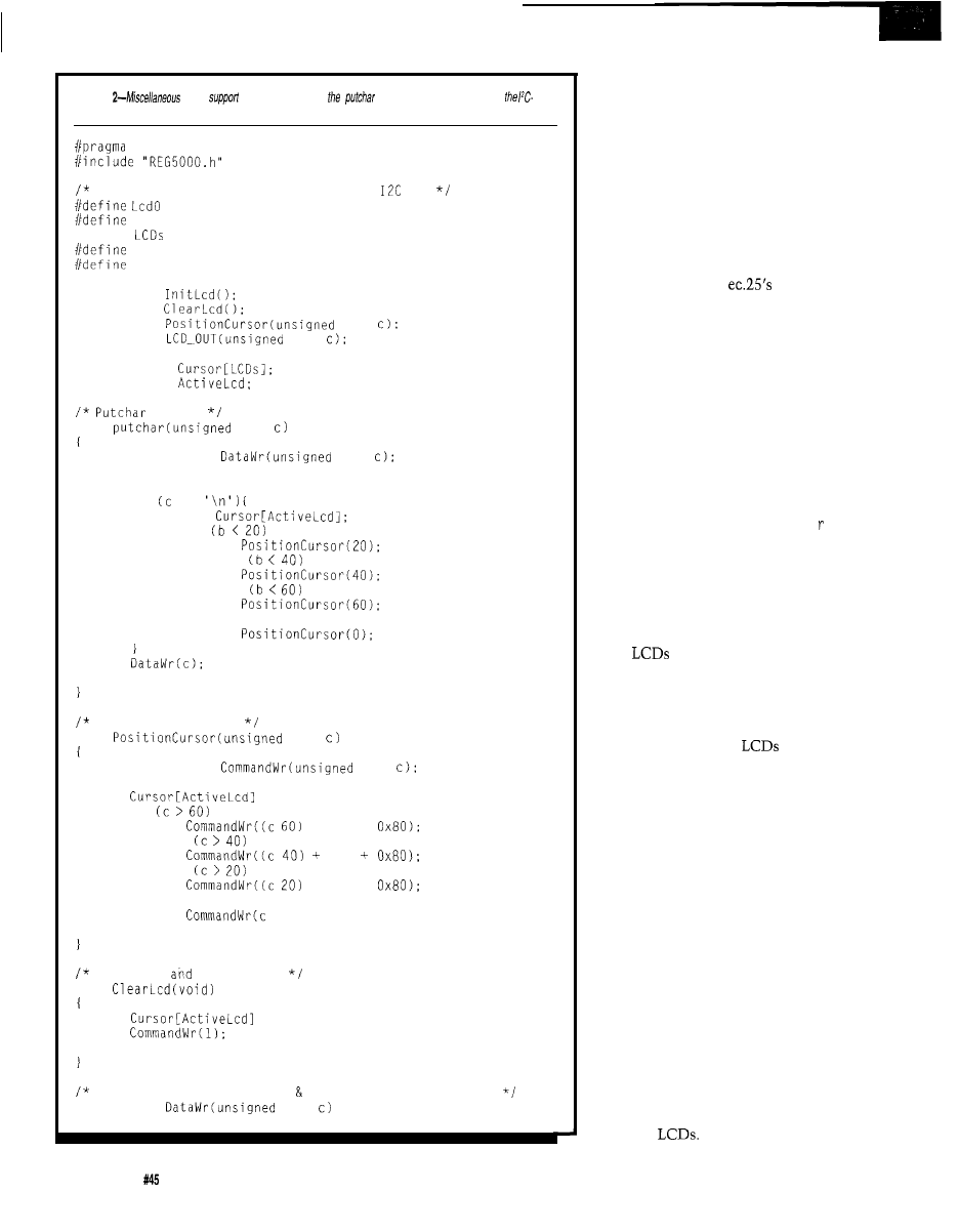
Listing
LCD
services include
function needed for driving
based 4 x 20 LCD panel.
LARGE CODE
Defined bits for LCD control over the
bus
0x42
Lcdl 0x44
#define
2
DEN 0x20
DRS 0x10
extern void
extern void
extern void
char
extern void
char
unsigned char
unsigned char
to LCD
void
char
extern void
char
unsigned char b;
if ==
b =
if
else if
else if
else
return:
Position LCD cursor
void
char
extern void
char
= c;
if
+ 84 +
else if
20
else if
+ 64 +
else
+ 0x80);
return;
Clear LCD
home cursor
void
= 0:
return:
Write to LCD data register handle cursor positioning
static void
char
(continued)
this case, the operational state could
be resumed or abandoned as appropri-
ate. Naturally, there are as many
approaches to fault recovery in
embedded systems as there are
embedded systems. Alas, this is one
area that must often be reinvented to
precisely suit the particular system.
LCD CONTROL
Last month I showed you some
code for driving the
K-based
keyboard. Space limitations prevented
me from finishing up with the display
side of things, so now I’ll wrap things
up with a discussion of the LCD
firmware support package. As with the
keyboard driver, you will find all of the
low-level functions required to handle
a standard character-based LCD panel
along with a way to hook into some
standard C library functions. Since we
picked up an ec.25compatible get key
replacement last month, this time
around we’ll acquire a new p u t c h a .
At the heart of just about every
character-based LCD is the HD44780
LCD controller. And although it does
have some idiosyncrasies, it is by any
estimation an unbelievably successful
design. To those who have employed
small
in their designs, the
problems associated with driving these
things are already understood. In any
event, much has already been written
on the subject, so I promise to be brief.
The fact that most
operate
under control of the HD44780 is, at
the same time, both an advantage and
a liability. It’s an advantage, because
once you’ve figured out how to use it,
you’re all set to handle just about any
character-based LCD on the market.
It’s a liability since because it must be
coerced to drive so many different
display configurations, it has a multi-
tude of options. Because of this, it is,
out of necessity, somewhat quirky.
Although there are a number of
nagging problems associated with
using the HD44780, perhaps the
biggest turns out to be the lack of
correspondence between physical and
logical cursor positions. In actuality,
this is not so much an LSI problem as
an implementation problem, but
nonetheless it is an affliction that is
unique to
72
Issue April 1994
The Computer Applications Journal
I’ll now describe some support
functions that I’ve coded up using C.
Although there isn’t a one-to-one
correspondence, I’ve already presented
some assembler routines in a previous
column that perform similar functions
to those I’ll show here. After all, how
many different things can you do to an
LCD, anyway? If you’re interested in
seeing how they compare against this
month’s offering, check out my
column in issue 35, “Putting
Through Its Paces.”
Something to keep in mind as you
follow Listing 2 is that the code is
written to support multiple LCD
panels over the same two-wire bus.
This capability only results in a slight
increase in code complexity.
At the bottom of the pile is
LCD-OUT. This routine merely passes a
couple of arguments from the C code
to the assembly level
driver. Since
I support multiple
and since, as
peripherals, they are addressable,
this stub routine must determine the
appropriate
address to pass to the
driver routine. The present code
supports two
which is enough
to prove a point, but in principle the
number could be much higher. You
might wonder what I could possibly
want with a bunch of
on such a
controller. In fact, it turns out I’m
already at work on a modular facility
surveillance/monitoring system that
uses an independent LCD for each
zone. As zones are added, a knockout
is punched out on the control panel
and an indicator display is added.
Since these low-level routines will
ultimately be pressed to serve
level stream functions such as
printf, Ihadtocomeupwithaway
to select the active display device on
the fly without too much disruption.
This is done by
ect
which
accepts as its argument a number that
denotes which display will become the
active LCD and will respond to
subsequent function calls. This
number is stored and is made globally
available for use by the various support
routines that need to know. The active
display remains live until a different
display is selected.
With intelligent peripherals such
as
the initialization sequence is
PAL
GAL
EPROM
EEPROM
FLASH
MICRO
XC1 736
PSD
5ns
Free software updates on BBS
Powerful menu driven software
up to 128 Channels
up to 400 MHz
up to
Variable Threshold Levels
8 External Clocks
16 Level Triggering
Pattern Generator Option
el
LA12100 (100 MHz, 24 Ch)
LA32200 (200 MHz, 32 Ch)
LA32400 (400 MHz, 32 Ch)
$2750
MHz,64 Ch)
Price is Complete
Pods and Software
included
W i t h P o d s
Software
200
sampling Rate
2 Analog Channels (2 ch. Digital Oscilloscope)
8 Digital Channels (8 ch. Logic Analyzer)
125 MHz Single Shot Bandwidth
up to 128K Samples/Channel
Call (201) 808-8990
Link Instruments
369
Passaic
Ave, Suite 100, Fairfield, NJ 07004 fax: 808-8786
The Computer Applications Journal
Issue
April 1994
7 3
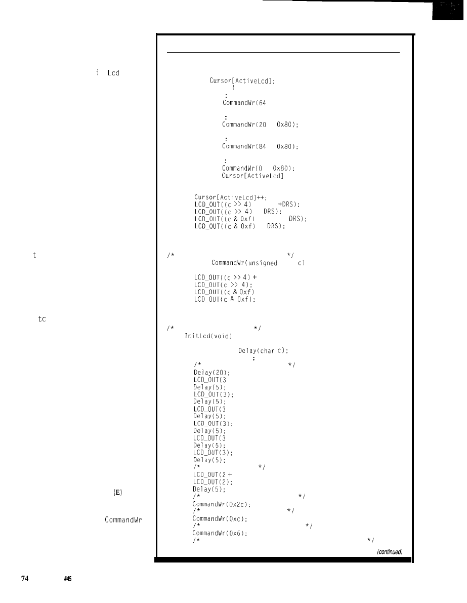
undoubtedly the most important step
you will perform. This is especially
true in this particular implementation
where I am using the display in nybble
mode. The function
I n t
performs
the necessary but admittedly arid steps
of putting the LCD into a known state,
configuring it for four-bit operation,
and finally setting up the specific
operational parameters. Incidentally,
this is, in all respects, the same
initialization routine that I described
in issue 35. If you want to know what
each instruction step actually does to
the LCD, refer back to that column.
Since the LCD is operated as a
write-only device, the current cursor
address is maintained in global RAM.
This information is not only needed
for keeping track of the cursor for
normal cursor positioning operations,
but must also be used to preserve the
apparent sequential nature of data as it
is written to the LCD. If you look at
Da
a W
r, which handles the transfer of
all displayable characters to the LCD,
you can see how the cursor must be
repositioned at key points where
display continuity would otherwise be
lost. On entry, the present cursor
address is copied to local storage and a
s w i
h
is used to catch addresses 20,
40, and 60. If the cursor is at any of
these addresses, the LCD needs fixing
so display data appears where it is
expected. Additionally, address 80 is
handled in a manner in which the
LCD wraps back around to address 0.
Finally, before the data character is
transferred to the LCD, the current
cursor address is incremented.
Now, in preparation for the dual
nybble transfers, the data byte is
dismembered and positioned. Control
bits are appended before the byte is
passed to the
LCD-OUT
routine. Since,
for displayable data, the destination is
the data register, the RS bit is raised to
indicate the appropriate target register.
Two transfers must be performed for
each nybble since the enable signal
must be pulsed for each transfer into
the LCD. Commands destined for the
command register use the
routine, which simply performs the
byte unpacking and transfer functions
without any of the gyrations
Da t a W r
has to do. In this case, the command
Listing
Z-continued
unsigned char b;
b =
switch(b)
case 20
+ 0x80)
break:
case 40
+
break;
case 60
+
break;
case 80
+
= 0:
break:
+ DEN
+
+ DEN +
+
return;
Write to LCD command register
static void
char
DEN);
+ DEN);
return:
Initialize LCD panel
void
extern void
unsigned char b
Put LCD in known state
+ DEN):
+ DEN);
+ DEN):
Set 4 bit mode
DEN);
4 bit, 2 line, 4x7 matrix
Display on, cursor off
Auto increment, shift right
Clear the LCD and set initial cursor address
Issue April 1994
The Computer Applications Journal
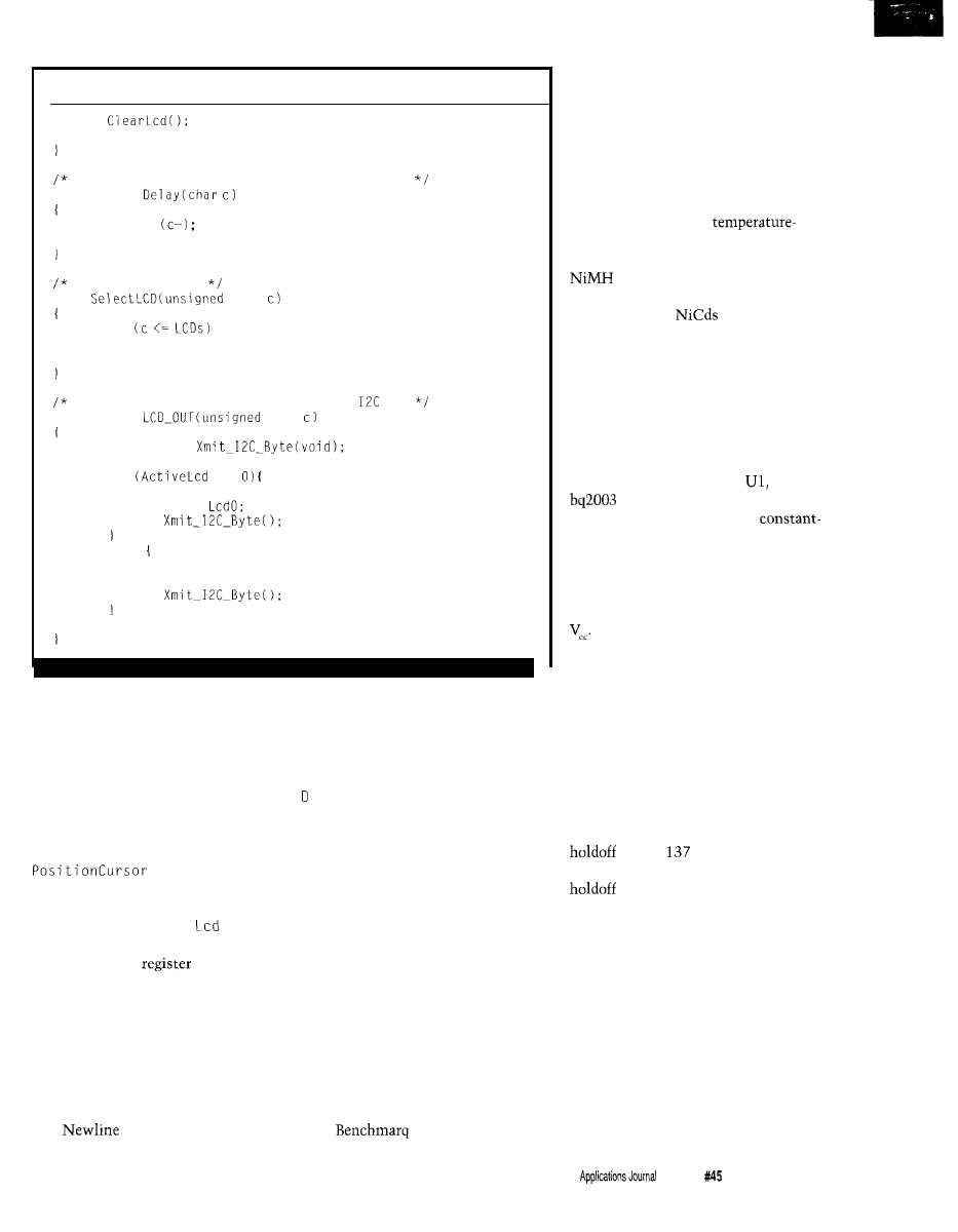
Listing
2-continued
return:
General delay used by initialization function
static void
while
return:
Select Active LCD
void
char
if
ActiveLcd = c;
return;
Assembler linkage: Output a byte over
bus
static void
char
extern void
if
==
B = c;
ACC =
else
B = c:
ACC = Lcdl:
return:
register is specified by holding RS low
during the transfer sequence.
Cursor positioning consists of
writing the cursor address into the
appropriate global RAM variable and
issuing a cursor positioning command
to the LCD’s command register. Of
course, by now we know that what we
see may not be what we get, so
determineswhat
adjustments must be applied to the
cursor address before it can be trans-
ferred to the LCD. Cl
ear
simply
issues the clear command to the
LCD’s command
and zeros the
appropriate cursor variable.
Finally, the
put c h a r
function
provides the low-level character
output routine that is used by the
stream I/O functions. This function is
what all the other stuff exists for. All
stream routines that output character
data do so using the
put c h a r
func-
tion.
characters are trapped at
this level, interpreted, and processed in
a consistent manner that advances the
cursor to the next physical display
line. All other characters are simply
transferred to the previously described
at
a W r.
Note that no checking is
performed for valid displayable data at
any level of processing described here.
BATTERY CONTROL
If all you’re using battery power
for is occasional backup, then you can
take some liberties in the design of the
charging system. On the other hand, if
the battery is the primary source of
power to your system, it makes sense
to devote a little more attention to
getting the support circuitry right.
This usually results in more power
from a given battery and a longer
operating life. In the case of the ec.25,
the battery manager is centered around
the bq2003 fast charge controller IC
from
Microelectronics.
Battery charging is accomplished
by applying constant current with a
fall back to a trickle level once a full
charge is attained. Negative delta
voltage is the method used to deter-
mine when fast charging is to be
terminated with maximum time used
as a failsafe backup. Although the
bq2003 fully supports
referenced charge termination, and
this is what you’d want to use with a
battery, this capability is not
used in my configuration since I’m
only supporting
at the present
time. Using voltage sensing to termi-
nate fast charge eliminates the added
components and interconnects
necessary for temperature monitoring
and simplifies the battery management
circuitry and the battery pack itself.
Figure 2 shows the battery
management card. All battery-related
activities are controlled by
the
fast charge IC. The bq2003 is
configured to control a linear
current source and is set up to use
negative delta voltage as the charge
termination criterium. These two
selections are made by respectively
pulling SNS to ground and DVEN to
TS and TCO are strapped in a way
that inhibits temperature monitoring
since it is not used in this configura-
tion. The related TEMP output that is
used to indicate temperature status via
an LED goes unused also.
The charge initiation input,
CCMD, is grounded, which enables
automatic battery charging on either
application of power or when a battery
is connected. Tying TM1 and TM2 to
ground selects a negative delta voltage
time of
seconds and a fast
charge safety time of 360 minutes. The
time is the time after charge
initiation that the battery is not
monitored for maximum voltage and
negative delta voltage. This prevents
problems by allowing the battery’s
charging action to stabilize. The safety
time is the maximum time that the
battery will be held on fast charge
before the charging cycle is termi-
nated. This timeout should never be
reached under normal operating
conditions, which is precisely what it’s
all about: safety under abnormal
operating conditions.
The Computer
Issue
April 1994
7 5
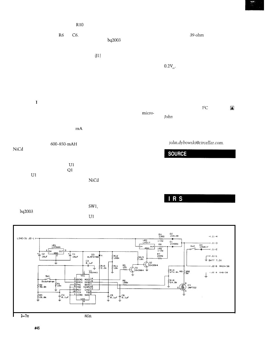
Attenuated battery voltage tapped
from a divider made up of R14 and
is presented to the BAT input through
an RC filter composed of and
The divider is set up to develop a
single cell voltage for the particular
battery being charged. This voltage is
constantly compared to the level at
MCV that sets the maximum single
cell voltage, in this case 1.8 V. If the
BAT input becomes greater than the
voltage on the MCV input, then
charging activity is terminated. This is
another safety feature.
Although the bq2003 can be used
as a switch-mode constant-current
source, here am using it simply as a
controller for an external linear
current driver. The constant-current
source uses a familiar circuit arrange-
ment based on VR2, the popular
LM3 17. The output current of 180
is set by R8 and, although not really a
fast charge rate, it is adequate to
ensure that a typical
battery, composed of six AA
cells, will attain a full state of charge
in a reasonable period of time. This
current source is controlled by
through switching transistors and
Q2. Once
determines that the
battery is on its negative voltage slope
(negative delta voltage), current from
VR2 is cut off. What remains is a small
charge-sustaining trickle charge
delivered through R4. This trickle
resistor has another purpose as well. If
the
determines that the
attached battery is at a depleted state
of charge (less then 1 V per cell), fast
charging is inhibited. In this case, it’s
up to the trickle resistor to bring the
battery up a minimal voltage level
before the
will energize the
constant-current source.
If you look at the battery connec-
tor
you will see there are a couple
of positive pins: one outgoing and one
incoming. When the battery is plugged
in, these pins are shorted together
since they go to a common connection
at the battery’s positive terminal. The
reason for this is to prevent driving the
unloaded output or VR2 (which rises
to a relatively high voltage) directly
into the main power feed of the
system. Recall that last month I
mentioned how the MAX639
power switch-mode regulator doesn’t
do well with anything over 12 V on its
input. Using two battery pins, one for
input and one for output, is the
simplest way of avoiding this type of
problem. All you have to do is diode
couple all the connections and every-
body is happy. Finally, there is an extra
unconnected pin on the battery
connector for future use.
Having the ability to automati-
cally do a discharge-before-charge on a
battery can be particularly useful
in preventing and correcting the
voltage depression effect popularly
known as “memory.” An on-demand
discharge cycle is started by pressing
a momentary push-button
switch that feeds into DCMD. When
detects a positive edge on DCMD,
the DIS push-pull output is turned on.
This in turn drives the n-channel FET
(Q3) into enhancement and effectively
grounds R9, a
power resistor.
This load is kept connected until the
battery is discharged to a nominal 1 V
per cell. This level is indicated by the
single cell voltage on the BAT pin
falling below the reference level of
When this voltage is reached,
DIS is released and a normal charging
sequence is started. All these different
activities are indicated with just a
single low-current LED (D3). Using
sequences of pulses with varying duty
cycles, a number of different events
can easily be differentiated.
Next month: an
infestation.
Dybowski is an engineer in-
volved in the design and manufacture
of hardware and software for indus-
trial data collection and communica-
tions equipment. He may be reached
at
For elements of this project, contact:
Mid-Tech Computing Devices
P.O. Box 218
Stafford, CT 060750218
(203) 684-2442
419
Very Useful
420 Moderately Useful
421 Not Useful
Figure
battery management card
specifically handles
but could handle other kinds of batteries with minor
changes
7 6
Issue
April 1994
The Computer Applications Journal

Russ Reiss
or data. To others the issues of “electronic signatures” and
authentication/validation come to mind. Yet to others it
means the use of computers (particularly microprocessors]
to provide protection of other objects such as automobiles,
homes, and valuable possessions. In this month’s Patent
Talk I’ll look at seven patent abstracts that embrace all
three of these areas.
Before getting into the mainstream, there’s one patent
Text section which is available with the latest
“U.S. Patent Search Claims Abstracts” database. It
appears that the novelty of this patent arises from the last
“and” clause, namely the special startup security feature in
which computer access is permitted only after an autho-
rized user is identified. It is very unlikely that a patent
could have been issued for any of the battery backup
techniques or the security aspect alone. But by combining
the two, a presumably unique device is created.
The next four abstracts describe patents that relate to
means for restricting access to a computer. Abstract 2 by
IBM (Great Britain) is perhaps the broadest. It covers the use
of passwords stored in nonvolatile memory to determine
the level of access permitted a given user. Crucial to the
patent is the concept of multiple levels of accessibility in
which a system manager has full access while users have
restricted access. This restricted access is achieved in
response to the user’s password, which causes a unique boot
I’d like to discuss that is somewhat different. The patent of
configuration to occur, as was previously specified by the
Abstract 1 was retrieved as a result of one of the search
system manager. Applicability to both personal computers
processes I employed since it includes the words
and networked systems seem possible here.
and “security.” It is an important patent for
Carrying the password concept a step further, Dell
microprocessor-based system designers to be aware of
Computers’ patent in Abstract 3 stores a “code word
because of its broad claims with regard to battery-backed
identification” in a PAL. A program desiring restricted
RAM techniques. I have included the more verbose Claims
operation reads the code word from this PAL and compares
Title
Patent
Number
Issue
Date
Inventor(s)
State/Country
5204840
1993 04 20
Mazur, Jeffrey G.
CA
Means and methods for preserving microprocessor memory
Abstract
Means and methods for preserving the RAM of an externally powered microprocessor on the occasion of a
loss in external power. When the power loss is detected, a signal is generated which initiates a sequence to
isolate the RAM and refresh it with an independent power supply. When main power is restored, the
microprocessor is restored to its precise location at the moment of power loss. Shutdown, startup, and
security routines are provided by software embodied in the system.
Ex Claim text
A system for preserving at least the main random access memory (RAM) of a computer system having a
power supply on the occasion of a sudden loss in power, said system comprising: a power loss detection
circuit adapted to sense a loss in the power supply of said computer system and emit a signal causing a
switchover circuit to isolate at least said main RAM from the computer system and cause at least said main
RAM to receive its power from an independent power source; and a power switchover circuit responsive to
said power loss detection signal to connect said independent power source to said memory; and an indepen-
dent power supply comprising an external transformer power supply, a rechargeable battery, a voltage
regulator, and a battery-charging circuit connected to said battery, said transformer power supply being
connected to said voltage regulator and to said battery-charging circuit, said battery being connected to said
voltage regulator for delivery of power to said switchover circuit; and a power-fall detection circuit comprising
a precision voltage reference, means for measuring the input voltage to said computer system, and a
comparator for initiating an NMI alert signal when said measured input voltage falls below said precision
voltage reference; and software operatively associated therewith and responsive to said power loss detection
circuit signal to initiate a shutdown routine when said signal is activated and to initiate a restart routine when
said signal is deactivated; and security means for interrupting a normal startup sequence of said computer
system to invoke a security procedure, whereby further use of said computer system would be allowed only
after identifying an authorized user.
U.S. Refs
4578774 4631701 4718038 4788661 4815032 4823308 4897631 4901283 4959774 4977537 5018096
The Computer Applications Journal
Issue
April 1994
7 7

it to one stored in the program. Access is permitted only if
the two code words match. This scheme is far reaching. The
PAL could be made an integral part of the system by
soldering it directly to the motherboard. Special versions of
operating systems, application code, device drivers, and the
like can then be restricted to running only on a system so
equipped with such a PAL. In contrast to a password which
restricts all but one (or a few) user(s), this code word
restricts the execution of software run by all users.
Appropriately named, Computer Security Corporation’s
patent in Abstract 4 is a plug-in expansion board for a PC. It
contains a number of components including a BIOS ex-
tension EPROM; scratchpad RAM; EEPROM for storing
passwords, audit trail log, encryption flags and the like; a
data encryption/decryption chip; and a clock chip. Along
with special software, these devices become security tools
that can restrict access to the system itself only to users
with valid passwords, keep data written to disk secure
through encryption, prevent unauthorized disk formatting,
prevent file copying, and even prevent circumvention of the
security system itself during boot. Although not mentioned,
the system could also restrict access to certain peripherals
(e.g., CD-ROMs or modems) only to authorized users.
Finally in this category, Abstract 5 covers a patent that
has the specific and singular function of restricting user
access to various peripheral devices on the system. The
typical password is requested during boot, which retrieves
user authorization information from memory. Thereafter,
every attempt to access a peripheral over the I/O channel is
monitored by hardware and trapped if not permitted.
Trapping involves setting a flag indicating security viola-
tion as well as blocking the access over the system bus.
Such a device would require access to the system bus, and
hence could take the form of an expansion card. However,
the inventors chose to refer to it as a “module,” which
would imply that they also see it taking a form which could
be mounted directly to the motherboard.
Shifting our attention now to another area, the next
abstract relates to the topic of “electronic signatures.” It
has long been promised that, in this age of a “paperless
society,” we would be able to replace the handwritten
signature with an electronic equivalent: a means for
Patent
Number
Issue
Date
Assignee
Inventor(s)
State/Country
5265163
1993 11 23
International Business Machines Corp.
Golding, Victor G., Speirs,
H.
GBX
Title
Abstract
Computer system security device
A computer system having a power-on password stored in nonvolatile memory wherein entry of the power-on
password by a system manager permits access to all of the computer functions. The system also has the facility of
at least one additional password held in nonvolatile memory, wherein entry of the additional password by a user
permits the system to boot in a manner preselected by the system manager. Preferably there are available a
plurality of additional passwords providing at least two different levels of security access to the system.
U.S. Refs
4757533 5012514 5058164 5115508 5204966
Patent Number
Issue Date
1992 03 24
Inventor(s)
State/Country
Assignee
Durkin, Michael D.; Stewart, Greg N.
TX
Dell Corporate Services Corporation
Title
Abstract
Digital computer code word identification system
A digital computer system has a central processor unit (CPU). A computer program, entered into the digital
computer system for execution thereof, has a program code word embedded at an arbitrary location therein. An
addressable programmable array of logic (PAL) is operatively connected to the CPU for receiving a READ signal
originated by the CPU at the address of the PAL, the PAL being programmed to output a portion of a preset array
code word in a response to the READ signal, and to output the remainder of the array code
in segments in
response to subsequent READ signals at the same address. A data bus, connected to receive and transmit the
portion and remainders of the array code word to the CPU for comparison with the program code word. The
program code word and the array code word are compared and, if identical, permit use of the program and do not
permit use when the program code word and the array code word are not identical.
78
April 1994
The Computer Applications Journal

Patent Number
Issue Date
Inventor(s)
State/Country
Assignee
US References
198807 12
Allen, Michael J.; Langlois, John
IL
Computer Security Corporation
2 7 , 2 5 1
US Class
380125
Int. Class
Title
Abstract
Security system for microcomputers
A security system for a personal computer in which hardware and software are combined to provide a
proof manner of protecting user access and file access. The hardware component of the system is an expansion
board for insertion into an expansion slot of the PC and has a first EPROM chip containing four portions of
machine code for initializing system function calls and for establishing the proper boot-processing of the PC; a
second RAM chip serving as scratchpad memory; a third EEPROM chip storing passwords, audit trail log,
protection and encryption system flags, and user-access rights; a fourth automatic encryption and decryption chip
for files of the PC; and a fifth clock chip for the audit trail. The software component includes a batch file that runs a
program in conjunction with the machine code on the EPROM of the expansion board ensuring access is gained
only for valid users. The code on the EPROM monitors all DOS 21 H file handling function calls, and initializes the
7CH interrupt vector for allowing the security system to access DOS and files thereof. During boot processing, the
video interrupt handler is monitored to prevent circumventing the security system. Hard disk format protection
is also provided by monitoring of the 13H interrupt function calls. Files may also be created that may not be copied.
verifying that a document was executed by only one
The final abstract relates to security associated with the
specific individual. This capability is of particular
use of IC Cards (also called “identification cards,” “chip
and convenience if the authentication must take
cards,” “memory cards,” and such]. Abstract 7 discusses a
place over a distance via telecommunication. Although
means of limiting the authorization period of such a card by
somewhat scant on detail, this patent could serve as a
“scrambling identification card information with time
starting point for someone wishing to pursue developments
information.” The system which reads the card can recover
in this field.
the time information and deny access if the card has
8
Patent Number
Issue Date
Assignee
Inventor(s)
State/Country
5202997
199304 13
Isolation Systems Limited
Arato, G. Peter
CAX
Title
Abstract
Device for controlling access to computer peripherals
An access control module restricts access to a computer system to authorized users and selectively controls each
user’s access to associated computer peripherals such as data storage units, printers, and communications
equipment. During startup of the computer system, a microprocessor associated with the module invokes a
software routine that requests entry of a valid user identification code. In response, the microprocessor retrieves
from a main nonvolatile storage unit, prerecorded information regarding the user’s authority to access each of the
peripherals and loads the information into a secondary storage unit comprising random access memory and an
address decoder adapted to retrieve data therefrom. Thereafter, the address decoder responds to each peripheral
address signal generated in the input/output channel associated with the computer system and retrieves from the
secondary storage unit the access information relating to the peripheral identified by the address signal. A latching
circuit generates and maintains a signal indicating a violation of computer security if the retrieved information
indicates that the current user of the computer system is not authorized to access the selected peripheral. The
microprocessor responds to the signal indicating security violation by applying signals to the input/output channel
which interrupt the operation of the computer system and interfere with access to the selected peripheral.
U.S. Refs
3368207 3398405 3473159 3508205 3585606 3725872 3872444 4000487 4264782 4601011
Issue
April 1994
The Computer Applications Journal

Patent Number
Issue Date
Inventor(s)
State/Country
US References
US Class
Class
Title
Abstract
1992 11 10
Graziano, James M.; Dziewit, Halina S.
c o
3401825.34
9132
Knowledge-based system for document authentication (apparatus)
The document authentication apparatus provides document authentication and authenticity capability.
Document authentication requires the person to be charged, apply an authentication mark on the document
indicating intent to authenticate the document. This requirement is analogous to a signature on a printed
document and is implemented in the document authentication apparatus electronically through the use of
both hardware and software. A program immediately checks the identicalness of the document at the
transmitting and receiving station through a high-speed comparison, locks in the document such that no
modification can occur, and awaits authentication handshakes from the two endpoints. Such authentication
is real-time and can be both hardware and software executable (i.e., password and physical confirmation).
Patent Number
Issue Date
Inventor(s)
State/Country
Assignee
US References
US Class
Class
Title
Abstract
1991 11 19
Bianco, James S.; Madsen, James T.; Ceppetelli, Michael; Fahy, John
CT
Control Module Inc.
380123
1 B 23128
1
Method and means to limit access to computer systems
In a preferred embodiment, a method of limiting access to computer systems which method includes
scrambling identification card information with time information so that the resulting code can be used for
only a limited period of time, thus preventing unauthorized persons from using the code at a later time. In
another aspect of the invention, one or more p-metal shields are embedded in an identification card, thus
identifying the card as being valid and also providing means to indicate when a valid card is being removed
from a card reader.
expired. Presumably, “scramble” implies that the time
information is not readily observable by someone wishing
to circumvent the protection by altering the card.
q
Russ Reiss holds a Ph.D. in
and has been active in
electronics for over 2.5 years as industry consultant,
designer, college professor, entrepeneur, and company
president. Using microprocessors since their inception, he
has incorporated them into scores of custom devices and
products. He may
be
reached at
or
corn.
422 Very Useful
423 Moderately Useful
424 Not Useful
Patent abstracts appearing in this column are from the
Automated Patent Searching (APS) database from:
25
Science Park
New Haven, CT 06511
(203)
or (800)
648-6787
databases include the abstract-only APS
version;
which contains the entire patent
without drawings;
for the complete
patent listing including drawings; and other specialized
databases for just chemical, computer, or European
patents.
The Computer Applications Journal
Issue
April 1994
83

The Circuit Cellar BBS
bps
24 hours/7 days a week
(203)
incoming lines
Internet
the
of
I’ve been doing /ate/y, I’m often asked
how someone can go a step further than the
we offer and gain
full net access. Most people get full access through the university
they work for or attend,
or through their employer who has full
network connectivity coming into the office. normally have to tell
people without these options to look info one of the commercial
systems that offer full access such as
or Delphi. However,
another alternative has recently come to my attention that
cost
you the same as it does just the
we provide: nothing but the
cost of a long-distance phone call.
The International
Association is offering free accounts
to anyone who asks. The only drawback is you must make a call to
either Washington D. C. or New Jersey to get to their access point.
They a/so offer an 800 number at very reasonable rates. They are
working on making more access points available across the country,
so you may eventually end up with a local node, so access would
cost nothing at Features include 14.4 kbps,
ffp,
Gopher, WWW, and more.
There are no hidden hooks or gofchas that can see, so if’s
certainly worthwhile to check out. For more information, contact
2020 Pennsylvania Ave. N. W., Ste. 852, Washington, DC 20006,
(202) 387-5446, or
to
With all the melting snow and spring rains associated with April,
people are bound to end up with wafer in the basement Detecting
fhaf water early can
prevent major damage, so decided to
devote most of the column this month a rather amusing and
interesting discussion we recently had on water defectors. The
second thread deals with the ratings found printed on the side of
most relays.
Water Detector
From: RICK
To: ALL USERS
have a need for some sort of simple safe circuit that
can detect water. Can anyone out there help me? Thanks
for any suggestions.
From: PAUL PETERSEN To: RICK
How much water? Gallons? Misty droplets? It makes a
difference in how we proceed.
84
Issue
April 1994
The Computer Applications Journal
From: JEFF BACHIOCHI To: RICK RETTER
I’ve seen some cheap water sensors made from a piece
of sponge which, when wet, expands to press a tiny switch.
As the sponge dries out it shrinks back, releasing the
switch. Real cheap. Varying the size will determine the
amount of water necessary to press and release the switch.
From: RICK RETTER To: JEFF BACHIOCHI
I guess I wasn’t specific enough. I need a detector for a
water sump pit. When the water is high, I turn on a pump
via the PC parallel port, and when the water level decreases,
I turn the pump off. can’t use the normal float switch that
come with sump pumps since the “travel” is too much.
From: JEFF BACHIOCHI To: RICK
Please explain further, normally when the pump goes
on you get a large reduction in water level and when the
pump turns off the back wash raises the level. This can
cause oscillations in the pump if the hysteresis isn’t large.
From: ED
To: RICK
Use two switches: a high limit and a low limit. Attach
a flag to the float and have it activate each switch in turn.
Run two bits into the PC and proceed as before.
Actually, if you’ve got a PC in the loop, I’d add a little
self-checking to the switch. Use a pair of optical or
proximity switches and make the flag long enough so it can
activate both of the switches when the water level is
between the limits. Then the PC can verify that the state
transitions make sense:
low = both were on: high now off and low now on
filling = low was on alone: both now on
high = both were on: high now on and low now off
draining = high was on alone: both now on
Note that you need to keep track of the previous switch
state. It’d be a good idea to add some timeouts to this so if
the pump goes on and the water level doesn’t drop you can
initiate manual bailing..

TIME
But, seeing as how you’ve got a PC in the loop, I’d also
add a mechanical emergency backup switch about half an
inch above the upper limit: it directly powers the pump
without any of this computer nonsense. If the PC goes out
to lunch, you can at least ensure that the basement won’t
fill up...
From: JIM NELSON To: RICK
Aww, these guys wanna make it too simple! You’ve
already tied up a PC, so why don’t we go all the way!
Oops-nonrhetorical question
What happens when
the PC is turned off?
But since you want to get complicated, Sensors maga-
zine is packed with high-tech fluid level sensors (laser,
ultrasonic, microwave, etc.) that will nicely complicate this
pump control. You’ll also want to consider your definition
of water level, since the transition between water and air is
vaporous.
OK, to get a line on that, your new and improved
detector will operate as a function of vapor pressure and
humidity, so you’ll need both humidity and temperature
sensors, and if the water isn’t absolutely pure, we’ll have to
know what it is, so add an ion mobility spectrometer
(what?) so you can pinpoint that vapor pressure. Factor in
air density, a function of altitude, local acceleration of
gravity, the number of holes in your dryer’s lint trap, and
the proximity of the moon, Alpha Centauri, and the Mars
Observer.
Clearly this is a job for fuzzy logic.
Now with fuzzy running on the Baby Cray humming in
the other corner of your basement, you’ll happily compen-
sate for some of the smaller effects on your pump control.
How many people can factor in the very small, yet provably
finite probability of a lightning strike which would com-
pletely obviate the need for even bothering with the pump?
A job for fuzzy!
We can’t forget the smoke and fire detectors you’ll need
to protect yourself against this seething mass of solution,
nor automatically triggered
fire extinguishers. And
active noise cancellation to quiet this buzzing mess.
Personally, I would rather go swimming in a lake than
in a basement, especially one crammed with molten
electronic junk glowing and blowing smoke bubbles.
P.S. Don’t forget a moisture detector-so you’ll know
when it all fails.
grin>
From: JOHN CONDE To: JIM NELSON
Well if you want to go slightly less than all the way,
I’ve seen three basic (simple, cheap) water-level detectors.
The first is a float switch, which you don’t like.
The second is an all electric probe where you have two
contacts close together at the level at which you want to
trigger supplied with a voltage from a supply will almost no
amperage. When the water level reaches the probe, voltage
will go to zero. That should be easy to detect. (Note this
method doesn’t work with pure water [an insulator], but
basement water should work fine.) To construct it, put a
meg resistor between the power supply and the plates, then
measure voltage from the plate side of the resistor. The
higher the voltage, the further apart the plates can be
(experiment]. Also, you will have to put some sort of
strainer around the probe to prevent solids from floating in
and shorting the plates, plus you have to clean the regu-
larly.
The third and lowest maintenance version takes a little
more construction. Inside a sealed tube you put a tempera-
ture sensor and a small heater, then mount the probe at the
height you want to sense water. Since water removes heat
much faster than air, the equilibrium temperature for the
probe (and the resistance through the sensor) will change
drastically. Also the time it takes to heat or cool the probe
will give you some built-in hysteresis. Of course, these
descriptions are short of specifics, but I hope they are
helpful.
From: CHRIS TYLKO To: JOHN CONDE
There’s a fourth simple way. My submersible sump
pump has a pressure sensor. It’s just a diaphragm that
activates a microswitch. A very small tube runs through the
AC power cable whose plug end must be open to atmo-
spheric pressure. As the water level goes four or so inches
above the top of the pump, it activates, emptying the pit
until the pump sucks air; by then the diaphragm lets go and
turns the pump off. In ten years, I’ve only had to replace the
microswitch.
Ironically, I guess, the pit is right below my HCS
control center (which is in the wine cellar), but there
and never will be-any connections between the system
and the pump.
From: JOHN CONDE To: CHRIS TYLKO
My list was not really intended to be exhaustive, I’m
quite sure there are even more simple ways (and probably
some astoundingly complex ones). The pressure switch
design is a good one. I would guess that most of the auto-
matic pumps use one. I agree about not controlling the
pump with a computer; some things are just too important
to trust to a computer.
The Computer Applications Journal
Issue
April 1994
8 5

From: JEFF BACHIOCHI To: CHRIS TYLKO
From: TOM NICKEL To: GARY JOHNSEY
Control the pump through the HCS! Never, is right!
However you may wish to keep a record of pump activity or
an emergency high-level sensor for those times [if/when)
the pump fails!
I was just looking a National’s 1993 Linear Application
Specific
data book. They have three components that
can measure/detect fluid levels: LM903, LM1042, and
LM1830.
From: CHRIS TYLKO To: JEFF BACHIOCHI
Actually a very good idea, considering when the pump
did fail it cost me a few sheets of 4x8 presswood.. .and you
know how quickly that stuff soaks up water!
What, in your opinion would be the simplest and
cheapest detector to hook up to the HCS!
From: JEFF BACHIOCHI To: CHRIS TYLKO
I like the tube with a closed bottom idea containing
multiple (at least two) hall effect switches. A Styrofoam
doughnut [containing a magnet) is placed on to the tube.
The float rises and falls with the water level, the sensors
detect it passing various points, the electronics stay dry,
and you decide how to interpret the data (turn on alarm,
pump, or call flood control central)!
I can suggest one method to not use: Some time back, a
few of my friends were living in a studio which had a
notoriously leaking/flooding basement problem. We set up
an old snare-drum stand with a piece of coat hanger wire,
chunk of Styrofoam, microswitch, and a “yelping” automo-
tive-type intrusion alarm, borrowed from their truck. The
idea, of course, was that rising water would case the “float”
to float and trigger the switch. Problem was, the automo-
tive alarm device had poor immunity to power line spikes (I
guess) because it would false trigger, usually in the wee
hours of the morning. Needless to say, the system was
quickly disarmed and the basement promptly flooded! (My
engineering skills have improved a tad since then, I don’t
use as many coat hangers in my new designs.)
From: DAN HOPPING To: CHRIS TYLKO
Another cheap detector would consist of two metal
thumbtacks (the contacts) pushed into the jaws of a spring
wooden clothespin (the force). The contacts (normally open)
held apart by an aspirin (the detection device). Water would
melt the aspirin and the contacts would close.
Assuming you have a pump, I would use the float
switch on the pump unit as an input.
Assuming you didn’t, I would get a piece of Styrofoam
and mount a microswitch on the top surface (the kind with
a cantilever arm). Place the arm through a hole in the
center of the foam piece and adjust the switch’s position so
that if the Styrofoam raises off the floor at all, the switch
closes.
A simple moisture detector I have used in the past is to
press two wires together using one of those magic expand-
ing sponges (you know the ones that look like a sheet of
paper, then when you put them in water they pop into a full
sized sponge). They expand with a remarkable (relatively)
amount of force and have no problem closing the contacts.
They have an almost instant response to water. I made a
few fixtures up with a battery and some surplus Sonalerts.
Cheap and simple. Great for under the sink and behind the
fridge. I *never* trust my own plumbing connections...
By the way, you can reflatten those little sponge
actuators by putting them in a vise and letting them dry out
again.
From: PELLERVO
To: JOHN CONDE
From: GARY JOHNSEY To: CHRIS TYLKO
I once needed to maintain the water level in a bucket,
quick and cheap. So I pulled the water level sensor and
water control solenoid out of an old clothes washer. The
switch contacts were sealed and not directly exposed to
moisture; probably one reason they outlasted the
old washer.
However, I like Jeff’s Styrofoam float idea, especially if
you can seal the contacts. Maybe a glass-encapsulated reed
switch? Put the magnet on the float and either paint it or
dip it in that liquid rubber like stuff used to insulate pliers
handles. Or, maybe not. Just a thought.
happen to have an experience with the water-level
sensing using a couple of electrodes and a resistance-sensing
trip circuit. Turned out to be exactly what you mention
about the frequent need for cleaning! There were a couple of
reasons in my case. One was that the water was hot and
tended to condense on the insulators of the electrodes. The
other one is that the DC principle causes electrolytic action
on the electrodes. That action tends to anodize one of them
and make it something similar to a low-leakage capacitor.
The commercial water resistance measurement
electrodes are made of platinum and they are always
operated on AC, not DC, which makes the tripping circuit a
little more complicated. Not necessarily much-think of
86
Issue
April 1994
The Computer Applications Journal
the indicators on commercial water purifiers (deionizer
cartridges). You just have a
supply in series with a
current-limiting resistor, a neon bulb, and the sensing
electrodes. If the water becomes conductive (or the level
reaches the electrodes), then the light comes on. You could
glue a photocell to the neon bulb and have the sensor.
From: JIM NELSON To: PELLERVO KASKINEN
A better, but more complicated, principle is to use the
high dielectric constant of water and, instead of resistance,
measure the capacitance of the probe. While typical
insulating materials have a dielectric constant of about 2-5,
water exhibits a high constant of 71 and is therefore quite
easy to detect by the capacitive principle.
I do like the index-of-refraction stunt that’s behind the
immersible acrylic plastic sensors you described. Sounds
like something that could be nicely packaged-an LED and
a detector/amp die cast in the same plastic package-if it
could be sealed, and if water-borne contaminants and
organic life (crud) accreting to the immersed surfaces didn’t
become a problem. Are such units available off the shelf?
From: PELLERVO KASKINEN To: JIM NELSON
Another recently popular method is to use an acrylic
As to the fouling, if you invent something that those
(Perspex, Lucite, etc., trade names) rod with one prismatic
little critters in water would not foul, you would be a rich
or conical end and one flat end. You shoot a beam of light
man. But there are differences and then there are differ-
into the flat end. If it comes back, the conical end is not
ences! Acrylic by its water absorption characteristics is not
immersed. If the light is lost, the conical end is immersed
the greatest. Polystyrene might actually sometimes beat it.
in something more optically dense than air, (i.e., in water).
But of course, glass is superior and quartz is the best as far
This same principle is used on some fuel gauges on kero-
as I know. However, I have not kept an eye on the commer-
sene lamps and/or heaters, with a staggered prismatic end
cial availability of these devices. I would think there must
on the rod. You see a different pattern depending on which
be some sources, as this is not such a novel idea any more.
ends are immersed and which are up in the dry.
My first exposure to them was already more than 20 years
The BCC52 controller continues to be
Micromint’s best selling single-board com-
puter. Its cost-effective architecture needs
only a power supply and terminal to become
a complete development system or
board solution in an end-use system. The
BCC52 is programmable in BASIC-52, (a
fast, full floating point interpreted BASIC), or
assembly language.
The BCC52 contains five RAM/ROM
sockets, an “intelligent” 27641128 EPROM
programmer, three
parallel ports, an
auto-baud rate detect serial console port, a serial printer port, and much more.
B-bit CMOS processor w/BASIC-%
counter/timers
Much more!
. Console RS232
detect
Line
E-bit parallel ports
B C C 5 2
Controller
board
BASIC-52 and RAM
$ 1 8 9 . 0 0 S i n g l e
Low-power CMOS
of the
$199.00
to
temperature version
$ 2 9 4 . 0 0
Low-power CMOS, expanded BCC52
RAM
$ 2 5 9 . 0 0
CALL FOR OEM PRICING
MICROMINT, INC.
We’re Small,We’re Powerful,
And We’re Cheaper.
MMT-188
E B
2 serial
ports
3 programmable parallel
l
capable
powerfail detect interrupt
and reset
counter-timers
watch dog timer
expansion connector
ALSO AVAILABLE:
MMT-196,
In
fact,
you’ll get the best product for about
half the price. If you’re interested in getting the
most out of your project, put the most into it.
For the least amount of money.
Call us today for complete data sheets, CPU
and availabilitv.
Work
Welcome. Call or fax for
complete data sheets
4
2308
East Sixth Street
SD 57006
Phone (605)
8521
Fax (605)
S
M A L L
B
UT
W
E
’
R E

ago, although it was only for visual feedback rather than for
electronic signaling. It was, by the way, used in a kerosene
heater by the British subsidiary of the Aladdin company,
which is based in my former home town, Nashville. I think
the small critters that live in water do not like the kerosene
too well..
From: LARRY G NELSON
To: PELLERVO
I used the index-of-refraction technique in 1975 to
measure height in a column of fluid. Picture a long line of
triangles in a tube with the flat side along the wall of a long
tube. The
were on the top half of each triangle with
the detector on the bottom half. This was cleaned up and
fed to some TTL glue to encode the binary data and used to
indicate the level to a bar graph as well as to the computer
running the equipment. It worked quite well and was
considerably cheaper than the competition at the time
while looking high tech.
Relay ratings
From: STEVEN SUN To: ALL USERS
have a question about relay contact ratings. I am
trying to control a signal line in a car. According to the car
manufacturer, the maximum amperage on that signal line is
10 amps. I am wondering if I can use a relay with a contact
rating of 1 amp at 125 VAC to control this signal line. My
understanding of the contact rating is that it will handle a
maximum of 125 watts. Since the car signal line is limited
to 12 watts, that relay should be able to handle it. By the
way, the relay contact is normally closed, so it should be
able to handle the
current flow almost continu-
ously.
Can anyone please explain to me what exactly does the
contact rating on a relay mean? Any assistance will be
greatly appreciated.
From: ED
To: STEVEN SUN
Contact ratings can be tricky, but the rule of thumb is
that you may not exceed any part of the rating.. .no matter
how innocent it may seem.
For example, if the rating is given in terms of AC volts
you cannot apply any part of that
to DC voltages or
currents. The reason is simple: the arc created across
contacts as they open will self-extinguish if it’s driven by
AC current, but it’ll just keep burning away on DC. Small
relays have roughly the same AC and DC current ratings at
88
Issue
April 1994
The Computer Applications Journal
a
given voltage, but the rating is voltage-dependent: higher
voltages mean lower currents. The ratings for larger relays
can differ by orders of magnitude, so don’t extrapolate
upward!
If a relay contact is rated at 1 amp at 125 VAC, that
means if you apply 125 volts AC, the contact may not carry
more than 1 amp. It does not mean the relay can handle any
combination of voltage and current that equals (1 A) (125
VAC) = 125 volt-amps AC. That prevents you from trying to
run 125 A at 1 VAC..
is obviously improper.
There is a difference between the “carrying” rating and
the “interrupting” rating, but for typical small relays you
only see the latter because you’re using the relay to open or
close a power circuit. If you can guarantee that the relay is
always cold-switched (meaning the contacts open or close
only when they’re not carrying any current) then you can
use the “carrying” rating, but in most applications the
“interrupting” rating is the one you’ve got to use.
Bottom line: if you want to switch a 12-V circuit
carrying 10 A, you need a power relay rated for service at 12
V and 10 A..
else just won’t work.
I bet that’s what you figured, but you were hoping there
was a loophole..
We invite you call the Circuit Cellar BBS and exchange
messages and files with other Circuit Cellar readers. It is
available 24 hours a day and may be reached at (203)
1988. Set your modem for 8 data bits, 1 stop bit, no parity,
and 300, 1200, 2400, 9600, or
bps. For information on
obtaining article software through the Internet, send
to
Software for the articles in this and past issues of The
Computer Applications
may be downloaded from
the Circuit Cellar BBS free of charge. For those unable to
download files, the software is also available on one 360K
IBM PC-format disk for only $12.
To order Software on Disk, send check or money order
to: The Computer Applications Journal, Software On Disk,
P.O. Box 772, Vernon, CT 06066, or use your VISA or
Mastercard and call (203) 875-2199. Be sure to specify the
issue number of each disk you order. Please add $3 for
shipping outside the U.S.
425
Very Useful
426 Moderately Useful
427 Not Useful

In the Citadel
0
iber optic metropolitan area networks promise to bring me more information bandwidth than was
previously ever conceived possible (or desired). But do really want all of that bandwidth and the “intelligence”
that is imposed on the otherwise innocent carriers?
Remember when you had to climb up on the roof to turn the antenna just so to get the TV to receive the four or five broadcast
channels that were available in your area? It was a bit surreal having a receiver capable of picking up more than 60 channels where
only three or four would have anything on them. Even though I knew there were only four channels, periodically I would methodically
tune to each one hoping to catch a new station, but finding none, would always return to my favorite channel anyway. I guess back
then, one channel would have been enough for me.
Next came the proliferation of cable systems and the rise of the superstations. The providers called this progress, because now
had more than 100 channels, and most of them carried some kind of “intelligence.” Intelligence in this case being defined as an analog
waveform modulated on the carrier wave. I don’t want to quibble over terms, but the trouble is most of the “intelligence” on this plethora
of offerings is just not “intelligent.” I suppose must be on an extreme edge of the demographics curve, but I just don’t appreciate QVC,
E!, DAETC, and all the other mindless, narrow-focus channels that are being offered. Even though I have all these channels to choose
from, I still am mostly confined to a small number of channels that I consistently view.
Now the providers want to offer me hundreds(!) of channels, with interactive TV to boot. I have to ask myself if I really want, or
need, this kind of service. It’s a sad statement indeed when someone who is as much a technophile as me ponders whether or not to
take part in emerging technology. I guess I’m not convinced I need a few hundred channels more of the trash that the providers
consider entertaining. It is interesting that the ads for these systems promise interactive learning, video conferences, and an
electronic democracy, when I have an inkling it will more likely contain shows like The Interactive Dating Game, Holographic Lifestyles
of the Obscenely Rich, not to mention too many channels of interactive psychics, video sex, and the Nintendo channel.
Bah! Who needs it?!?
I suppose the only thing this new wave of bandwidth happiness could offer me is the chance for more intellectually stimulating
programming, but I don’t think this is likely to happen as long as the same cloistered crew of media pundits who brought you too much
of the
trial rethink what their mission is. I mean, do they want to educate us or stupefy us? Some great thinker once said that an
educated person is more likely to become free; it scares me to think that educating us is the last thing the moguls and the kingpins of
the media machine want to do....
6
Issue
April 1994
The Computer Applications Journal
Wyszukiwarka
Podobne podstrony:
circuit cellar1996 04
circuit cellar1991 04,05
circuit cellar2001 04
circuit cellar2002 04
circuit cellar1995 04
circuit cellar2004 04
circuit cellar1992 04,05
circuit cellar2000 04
circuit cellar1990 04,05
circuit cellar2003 04
circuit cellar1997 04
circuit cellar1996 04
circuit cellar1991 04,05
circuit cellar2001 04
circuit cellar1996 04
circuit cellar1992 04,05
circuit cellar1995 04
circuit cellar1997 04
więcej podobnych podstron